1
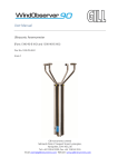
Intrinsically Safe
WindObserver
Anemometer
User Manual
Doc No. 1360-PS-0001
Issue 03
Gill Instruments Ltd recognise all trademarks
Gill Instruments Limited
Saltmarsh Park,
67 Gosport Street,
Lymington,
Hampshire.
SO41 9EG
UK
Tel: +44 (0) 1590 613500
Fax: +44 (0) 1590 613501
E-mail: [email protected]
Website: www.gill.co.uk
Gill Instruments Ltd
_______________________________________________________________________________________________________
Intrinsically Safe WindObserver Anemometer
Doc. No. 1360-PS-0001
Page 1
Issue 03
September 2002
Gill Instruments Ltd
_______________________________________________________________________________________________________
WARNING:
ENSURE CORRECT
SUPPLY VOLTAGE
IS SELECTED ON
POWER SUPPLY
BEFORE
INSTALLATION
Intrinsically Safe WindObserver Anemometer
Doc. No. 1360-PS-0001
Page 2
Issue 03
September 2002
Gill Instruments Ltd
_______________________________________________________________________________________________________
1. FOREWORD................................................................................................................................................5
2. PACKING LIST...........................................................................................................................................5
3. INSTALLATION.........................................................................................................................................6
3.1 Mounting................................................................................................................................................6
3.2 Alignment...............................................................................................................................................6
3.3 Sealing....................................................................................................................................................6
3.4 Corrosion................................................................................................................................................6
3.5 Earthing..................................................................................................................................................6
3.6 Cabling....................................................................................................................................................6
3.7 General....................................................................................................................................................6
4. SYSTEM OPERATION...............................................................................................................................7
4.1 Wind Measurement ................................................................................................................................7
4.1.1 Measurement Sampling Rates and Averages...................................................................................7
4.2 System Configuration.............................................................................................................................7
4.3 Default System Configuration................................................................................................................7
5. CONNECTION TO A PC OR OTHER DEVICE........................................................................................8
6. USING THE ANEMOMETER WITH A COMPUTER AND YOUR SOFTWARE..................................9
6.1 Digital Serial Output Formats.................................................................................................................9
6.2 Digital Format Notes............................................................................................................................12
6.3 Status Code...........................................................................................................................................12
7. ANEMOMETER SOFTWARE COMMANDS.........................................................................................14
7.1 Configuration Mode.............................................................................................................................14
7.2 Polled Operation...................................................................................................................................14
7.3 Output Mode.........................................................................................................................................14
7.4 Output Units.........................................................................................................................................14
7.5 Measurement Average..........................................................................................................................14
7.6 Output String Padding..........................................................................................................................14
7.7 Baud Rate.............................................................................................................................................15
7.8 Sample Period.......................................................................................................................................15
7.9 Parity.....................................................................................................................................................15
7.10 Vertical Padding.................................................................................................................................15
7.11 Unit Identification...............................................................................................................................15
7.12 Diagnostics.........................................................................................................................................15
8. DRAWINGS...............................................................................................................................................16
1086-G-045 Anemometer Installation Details...........................................................................................17
1360-G-026 Type IIc I.S. Anemometer Dimensions.................................................................................18
1360-G-028 I.S. WindObserver II System Diagram Sheet 1 of 2..............................................................19
1360-G-028 I.S. WindObserver II System Diagram Sheet 2 of 2..............................................................20
1360-M-039 I.S.Terminal Arrangement.....................................................................................................21
1360-G-043 I.S. PCI Unit...........................................................................................................................22
9.1 Specification.........................................................................................................................................23
10. POWER AND COMMUNICATIONS INTERFACE..............................................................................25
10.1 PCI......................................................................................................................................................25
10.1.1 External Connections...................................................................................................................25
10.1.2 Electrical Power Requirements....................................................................................................25
10.1.3 Internal Supply ...........................................................................................................................25
10.1.4 External Supply ...........................................................................................................................25
10.1.5 RS422 Interface...........................................................................................................................25
10.1.6 Cable Requirements.....................................................................................................................25
10.1.7 Environmental..............................................................................................................................26
10.1.8 Material........................................................................................................................................26
10.1.9 EMC.............................................................................................................................................26
APPENDIX 1..................................................................................................................................................27
SUMMARY OF ABBREVIATIONS USED IN THIS MANUAL...........................................................27
OPTIONAL EXTRAS................................................................................................................................29
Intrinsically Safe WindObserver Anemometer
Doc. No. 1360-PS-0001
Page 3
Issue 03
September 2002
Gill Instruments Ltd
_______________________________________________________________________________________________________
APPENDIX 2..................................................................................................................................................30
PRODUCT APPROVALS.........................................................................................................................30
SIRA CERTIFICATION........................................................................................................................30
Intrinsically Safe WindObserver Anemometer
Doc. No. 1360-PS-0001
Page 4
Issue 03
September 2002
Gill Instruments Ltd
_______________________________________________________________________________________________________
1. FOREWORD
This manual refers to the Gill Instruments Ltd Intrinsically Safe WindObserver ultrasonic
anemometer. It is an extremely sophisticated instrument and to achieve optimum
performance we recommend that you read the whole of this manual before proceeding
further with use.
The Solent range is in continuous development and so specifications may be subject to
change without prior notice.
2. PACKING LIST
•
•
•
•
•
•
Intrinsically Safe 2 axis anemometer
Mounting kit
This manual
Intrinsically Safe Power & Communications Interface
Anemometer Connector 20 way
3m Anemometer Cable
Intrinsically Safe WindObserver Anemometer
Doc. No. 1360-PS-0001
Page 5
Issue 03
September 2002
Gill Instruments Ltd
_______________________________________________________________________________________________________
3. INSTALLATION
3.1 Mounting
The Anemometer should be mounted on a suitable surface as defined in drawing 1086-G045 shown in Section 8, using the mounting kit supplied and described in the Packing
List. The anemometer does not require any adjustment - do not attempt to
dismantle, or warranty and calibration will be void.
3.2 Alignment
The anemometer should be set to point North, see drawing 1360-G-026 as shown in
Section 8, (or to some other known reference direction). This is facilitated by slots in the
base for the mounting screws, which allow rotation of the anemometer for fine alignment.
3.3 Sealing
The connector area at the base of the anemometer should not be directly exposed to
moisture or solvents, as whilst the connectors are sealed when mated, the anemometer is
vented to air at the base to avoid pressure build up. Therefore use the gasket provided
in the mounting kit.
3.4 Corrosion
Careful note should be taken of the possibility of galvanic corrosion by incorrect
mounting. It is vital that only stainless steel fixings are used and that the instrument is
insulated from the mounting surface with the rubber gasket. This will ensure that the
anemometer will provide long service under extreme conditions.
3.5 Earthing
The system must be earthed in accordance with local or national regulations. Intrinsically
safe operation will be affected if incorrectly earthed.
3.6 Cabling
Ensure that strain relief measures are employed when installing the cables. Do not allow
the whole weight of the cable to be applied to the connector.
3.7 General
DO NOT attempt to remove or unscrew any fixing. Any unauthorised adjustment of the
unit could affect intrinsic safety and will void the warranty.
The unit must be installed in accordance with the Control Drawing 1360-G-028, Section
8.
Intrinsically Safe WindObserver Anemometer
Doc. No. 1360-PS-0001
Page 6
Issue 03
September 2002
Gill Instruments Ltd
_______________________________________________________________________________________________________
4. SYSTEM OPERATION
There are two modes of operation, as follows:
Wind measurement
Normal operating mode
System configuration
Used to reconfigure system. See Section 7.
4.1 Wind Measurement
This is the normal operating mode. Data is output once per second or four times per
second.
4.1.1 Measurement Sampling Rates and Averages
There are two sampling rates:
1) One output per second
50ms sample rate - block average of 19
measurements / output.
2) Four outputs per second 50ms sample rate - block average of 4
measurements / output.
The block averages of 19 and 4 measurements are due to the last sample period being
required for measurement scaling and output formatting.
4.2 System Configuration
This mode will allow the user to configure the anemometer via the RS422 interface. It is
entered and exited by transmitting control characters to the anemometer, see Section 7.
The system will then expect a single character and number sequence which will change
mode, wind speed output etc. No security will be included in this mode, but only valid
user entries will be accepted. See Section 7 for the full list of commands.
4.3 Default System Configuration
The anemometer is factory configured as follows:
P1:
G1:
M2:
U1:
B3:
F1:
NA:
O1:
V1:
1 output per second
Averaging Off
ASCII Polar Continuous
m/s
Baud rate set to 9600
8 data bits, no parity
Poll address 'A'
Comma Separated Variable output
Vertical Padding Disabled
Intrinsically Safe WindObserver Anemometer
Doc. No. 1360-PS-0001
Page 7
Issue 03
September 2002
Gill Instruments Ltd
_______________________________________________________________________________________________________
5. CONNECTION TO A PC OR OTHER DEVICE
Connection to a PC or other device requires the use of:
1) An Intrinsically Safe Power and Communications Interface (PCI) – MUST BE USED
UNDER ALL CIRCUMSTANCES.
2) PCI to PC / Other device cable - Digital RS232 9 way “D Type” connector.
The PCI supplies power to the anemometer electronics and provides conversion of the
RS422 signal sent by the anemometer to the RS232 signal required by the PC. The PCI
requires connection to the mains; for more details refer to Section 10. Computers other
than IBM PCs or other compatibles may require a customised cable for connection to the
PCI.
The anemometer outputs wind data through a single 20 way circular connector in the
base. Details of the pin allocations can be found in Section 9. Data is provided in Digital
format.
Baud rate options are:
1) 1200
2) 2400
3) 4800
4) 9600
5) 19200
6) 38400
Three serial data formats are available:
1) 1 start, 8 data, odd parity, 1 stop
2) 1 start, 8 data, even parity, 1 stop
3) 1 start, 8 data, no parity, 1 stop
The selection of different baud rates and data formats require the user to confirm the
selection so that the interface between the device and the anemometer cannot be set in a
mode that is not valid for both units.
Intrinsically Safe WindObserver Anemometer
Doc. No. 1360-PS-0001
Page 8
Issue 03
September 2002
Gill Instruments Ltd
_______________________________________________________________________________________________________
6. USING THE ANEMOMETER WITH A COMPUTER AND
YOUR SOFTWARE
The user need not necessarily use a terminal emulator to store and analyse data being sent
by the anemometer. This section describes the modes and format of the data output by the
anemometer so that you can write your own software.
6.1 Digital Serial Output Formats
There are five wind data modes in ASCII format, one in Binary format and one network
identification response available from the serial output of the anemometer as follows:
Mode 1
ASCII, UV, Continuous
<STX><ID>,±UUU.UU,±VVV.VV,U,SS,<ETX>CC<CR><LF>
where:
<STX>
Start of string character (ASCII value 2)
<ID>
Anemometer IDentification (A-Z)
±UUU.UU
‘U’ axis velocity (*1)
±VVV.VV
‘V’ axis velocity (*2)
U
Units (M=m/s, N=knots, P=mph, K=kph, F=fpm)
SS
Status data
<ETX>
End of string character (ASCII value 3)
CC
Checksum of all Characters between <STX> and <ETX>
(HEX byte)
<CR><LF>
Carriage Return and LineFeed
Mode 2
ASCII, Polar, Continuous
<STX><ID>,DDD,MMM.MM,U,SS,<ETX>CC<CR><LF>
where:
<STX>
Start of string character (ASCII value 2)
<ID>
Anemometer IDentification (A-Z)
DDD
Direction in degrees
MMM.MM
Wind Magnitude (*3)
U
Units (M=m/s, N=knots, P=mph, K=kph, F=fpm)
SS
Status data
<ETX>
End of string character (ASCII value 3)
CC
Checksum of all Characters between <STX> and <ETX>
(HEX byte)
<CR><LF>
Carriage Return and LineFeed
Intrinsically Safe WindObserver Anemometer
Doc. No. 1360-PS-0001
Page 9
Issue 03
September 2002
Gill Instruments Ltd
_______________________________________________________________________________________________________
Mode 3
ASCII, UV, Polled
where:
<STX><ID>,±UUU.UU,±VVV.VV,U,SS,<ETX>CC<CR><LF>
<STX>
Start of string character (ASCII value 2)
<ID>
Anemometer IDentification (A-Z)
±UUU.UU
‘U’ axis velocity (*1)
±VVV.VV
‘V’ axis velocity (*2)
U
Units (M=m/s, N=knots, P=mph, K=kph, F=fpm)
SS
Status data
<ETX>
End of string character (ASCII value 3)
CC
Checksum of all Characters between <STX> and <ETX>
(HEX byte)
<CR><LF>
Carriage Return and LineFeed
Mode 4
ASCII, Polar, Polled
where:
<STX><ID>,DDD,MMM.MM,U,SS,<ETX>CC<CR><LF>
<STX>
Start of string character (ASCII value 2)
<ID>
Anemometer IDentification (A-Z)
DDD
Direction in degrees
MMM.MM
Wind Magnitude (*3)
U
Units (M=m/s, N=knots, P=mph, K=kph, F=fpm)
SS
Status data
<ETX>
End of string character (ASCII value 3)
CC
Checksum of all Characters between <STX> and <ETX>
(HEX byte)
<CR><LF>
Carriage Return and LineFeed
(*1) In Feet Per Minute output mode, the string changes to ±UUUU.U
(*2) In Feet Per Minute output mode, the string changes to ±VVVV.V
(*3) In Feet Per Minute output mode, the string changes to MMMM.M
Intrinsically Safe WindObserver Anemometer
Doc. No. 1360-PS-0001
Page 10
Issue 03
September 2002
Gill Instruments Ltd
_______________________________________________________________________________________________________
Mode 5
ASCII, UV, Polled, No Tri-State
where:
<STX><ID>,±UUU.UU,±VVV.VV,U,SS,<ETX>CC<CR><LF>
<STX>
Start of string character (ASCII value 2)
<ID>
Anemometer IDentification (A-Z)
±UUU.UU
‘U’ axis velocity (*1)
±VVV.VV
‘V’ axis velocity (*2)
U
Units (M=m/s, N=knots, P=mph, K=kph, F=fpm)
SS
Status data
<ETX>
End of string character (ASCII value 3)
CC
Checksum of all Characters between <STX> and <ETX>
(HEX byte)
<CR><LF>
Carriage Return and LineFeed
Mode 6
ASCII, NMEA, continuous
where
$IIMWV,Wc1,R,Wc2,Units,Valid,*cc<CR><LF>
‘$’
Start of string character
‘II’
Integrated instrument
‘MWV’
Mean wind direction and velocity
Wc1
Wind component 1
‘R’
Relative wind measurement
Wc2
Wind component 2
Units
Units ident
Valid
Valid flag
‘*’
Checksum delimiter
cc
Checksum
Wind Component Fields
Direction in degrees (DDD)
Wc1
Wc2
Wind speed (MMM.MM)
Units Field
Value
M
N
P
K
F
Intrinsically Safe WindObserver Anemometer
Doc. No. 1360-PS-0001
Units
m/s
Knots
MPH
kph
FPM
Page 11
Issue 03
September 2002
Gill Instruments Ltd
_______________________________________________________________________________________________________
Valid Field
‘A’
‘V’
Valid measurement
Invalid measurement
Checksum Field
Exclusive OR of all characters between ‘$’ and ‘*’ reported as ASCII hex.
6.2 Digital Format Notes
1) If wind speed is too low to calculate direction (below 0.5m/s) then the direction
parameter DDD, in ASCII modes, will remain blank in CSV mode. In fixed field
mode, direction freezes at last valid direction.
2) The checksum is the EXCLUSIVE OR of the 8 data bits of each character between
and excluding <STX> and <ETX>. The HEX value of the most significant and least
significant four bits of the result are converted to 2 ASCII characters for transmission.
3) If the anemometer detects a checksum error in the non-volatile memory, the following
ASCII string is output in place of the normal output:
**NO CONFIGURATION DATA**<CR><LF>.
4) In fixed field mode an error will result in value +99.999 for UV and Magnitude and
999 for direction being reported.
6.3 Status Code
A two character ‘Status code’ will be transmitted in the serial string. This value will
denote the system and measurement status. The codes are:
Code 00 - O.K.
This indicates that the system is operating correctly. The transducers signals are within
the required limits and no memory faults have occurred.
Code 01 - Transducer Pair 1 Failed.
This error occurs when there is a blockage in the path of transducer pair one, or when a
transducer has failed.
Code 02 - Transducer Pair 2 Failed.
This error occurs when there is a blockage in the path of transducer pair two, or when a
transducer has failed.
Intrinsically Safe WindObserver Anemometer
Doc. No. 1360-PS-0001
Page 12
Issue 03
September 2002
Gill Instruments Ltd
_______________________________________________________________________________________________________
Code 04 - Transducer Pairs 1 and 2 Failed.
This error occurs when there is a blockage in the path of transducer pairs one and two, or
when transducers have failed.
Code 08 - Non-Volatile Memory Checksum Error.
The non-volatile memory (EEPROM) holds the user set up, internal system parameters
and calibration data. If the internal checksum programmed in production does not match
the one calculated by the system during operation, then this status code will be flagged.
An EEPROM error could be caused by a faulty read/write cycle or a complete chip
failure.
Code 09 - Volatile Memory Checksum Error.
The volatile memory (SRAM) holds the data, which is used during the vector calibration
codes. If the internal checksum programmed in production does not match the one
calculated during system operation then this status code is flagged. The unit is operating
in uncalibrated mode.
Code 10 - System Gain at Maximum.
This indicates that an ultrasonic signal has been received but the receive gain had to be
set to maximum to recover the pulse. This is normally due to partially blocked transducer
paths. The wind velocity reported could be in error.
Code 50 - Marginal System Gain Condition.
This indicates that an ultrasonic signal has been received but a high receive gain was
required to recover the pulse. This code is asserted during high wind velocities. It may
also be caused by partially blocked transducer paths or partially failed transducers (low
efficiency). The wind velocity reported will be correct.
Code 51 - Measurement Average Building.
This code is set before the average period selected (3, 5,10 or 15 seconds) has been
reached. The reported velocities during this period are only the average calculated for the
length of time that the unit has been operational. This code only occurs after a power on
or exit from configuration mode.
NOTE Should any of these status codes other than code 00 appear consistently then the
unit will need to be returned to the manufacturer for repair.
Intrinsically Safe WindObserver Anemometer
Doc. No. 1360-PS-0001
Page 13
Issue 03
September 2002
Gill Instruments Ltd
_______________________________________________________________________________________________________
7. ANEMOMETER SOFTWARE COMMANDS
7.1 Configuration Mode
On, Modes M1, M2
On, Modes M3, M4
Off
*
*x (Where x is polling identifier A-Z)
Q
7.2 Polled Operation
Request Identification
Disable Polled Output
Enable Polled Output
Anemometer Poll
&
!
?
A-Z
The unit will only accept the following commands when in configuration mode:
7.3 Output Mode
ASCII, UV, Continuous
ASCII, Polar, Continuous
ASCII, UV, Polled
ASCII, Polar, Polled
ASCII, UV, Polled, No Tri-State
ASCII, NMEA, Continuous
M1
M2
M3
M4
M5
M6
7.4 Output Units
m/s
Knots
MPH
KPH
FPM
U1
U2
U3
U4
U5
7.5 Measurement Average
Off
3 Second
5 Second
10 Second
15 Second
G1
G2
G3
G4
G5
7.6 Output String Padding
Off Comma Separated Variable
On Fixed Field
Intrinsically Safe WindObserver Anemometer
Doc. No. 1360-PS-0001
O1
O2
Page 14
Issue 03
September 2002
Gill Instruments Ltd
_______________________________________________________________________________________________________
7.7 Baud Rate
2400
4800
9600
19200
38400
1200
B1
B2
B3
B4
B5
B6
7.8 Sample Period
1 Sample Per Second
4 Samples Per Second
P1
P2
7.9 Parity
8 Data, No Parity
8 Data, Even Parity
8 Data, Odd Parity
F1
F2
F3
7.10 Vertical Padding
V1 - Vertical Padding with Zero Disabled
V2 - Vertical Padding with Zero Enabled
The following are only applicable in modes 3&4.
7.11 Unit Identification
Set Identification to ‘x’
Nx
7.12 Diagnostics
Read Serial Number and Type
Read S/W Version
Read System Configuration
D1
D2
D3
REFER ALSO TO SECTION 6.3
Intrinsically Safe WindObserver Anemometer
Doc. No. 1360-PS-0001
Page 15
Issue 03
September 2002
Gill Instruments Ltd
_______________________________________________________________________________________________________
8. DRAWINGS
Intrinsically Safe WindObserver Anemometer
Doc. No. 1360-PS-0001
Page 16
Issue 03
September 2002
Gill Instruments Ltd
_______________________________________________________________________________________________________
1086-G-045 Anemometer Installation Details
.
Intrinsically Safe WindObserver Anemometer
Doc. No. 1360-PS-0001
Page 17
Issue 03
September 2002
Gill Instruments Ltd
_______________________________________________________________________________________________________
1360-G-026 Type IIc I.S. Anemometer Dimensions
Intrinsically Safe WindObserver Anemometer
Doc. No. 1360-PS-0001
Page 18
Issue 03
September 2002
Gill Instruments Ltd
_______________________________________________________________________________________________________
1360-G-028 I.S. WindObserver II System Diagram Sheet 1 of 2
Intrinsically Safe WindObserver Anemometer
Doc. No. 1360-PS-0001
Page 19
Issue 03
September 2002
Gill Instruments Ltd
_______________________________________________________________________________________________________
1360-G-028 I.S. WindObserver II System Diagram Sheet 2 of 2
Intrinsically Safe WindObserver Anemometer
Doc. No. 1360-PS-0001
Page 20
Issue 03
September 2002
Gill Instruments Ltd
_______________________________________________________________________________________________________
1360-M-039 I.S.Terminal Arrangement
Intrinsically Safe WindObserver Anemometer
Doc. No. 1360-PS-0001
Page 21
Issue 03
September 2002
Gill Instruments Ltd
_______________________________________________________________________________________________________
1360-G-043 I.S. PCI Unit
Intrinsically Safe WindObserver Anemometer
Doc. No. 1360-PS-0001
Page 22
Issue 03
September 2002
Gill Instruments Ltd
_______________________________________________________________________________________________________
9. TECHNICAL SPECIFICATION
9.1 Specification
I.S. Rating - European
For use in Zone 0, 1 and 2 Areas.
Rating
EEx ia (BS EN 50 020)
Gas Group
IIC
Temp Class
T5
Measurement Characteristics
Measurement velocity range 0 to 70m/s
Velocity resolution
0.01m/s
Velocity accuracy
±5% RMS
Direction resolution
1 degree
Direction accuracy
± 4 degrees
Note: Accuracy specification applies from 5oC to 35oC and for wind incidence within
±10o of horizontal.
Temperature Characteristics
Operating
-25oC to +60oC
Storage
-50oC to +75oC
Anem. Electrical
Supply
Current
6 to 12V DC
30mA Peak
All circuits protected to 0.8 Joule
Environmental
Altitude
Humidity
Moisture ingress
0 to 3000m
5 to 100% RH
IP65
EMC
Emissions
Immunity
BS EN 50081-1:1992 (class B)
BS EN 50082-1:1992
Material
316 Stainless Steel
Intrinsically Safe WindObserver Anemometer
Doc. No. 1360-PS-0001
Page 23
Issue 03
September 2002
Gill Instruments Ltd
_______________________________________________________________________________________________________
Serial Interface
One Tx RS422 channel
One Rx RS422 channel
1200, 2400, 4800, 9600, 19200 and 38400 baud
Parity error check available (odd or even)
Serial output rate 1 per second or 4 per second
Physical
Size
Weight
380mm x 210mm
2kg
Connector
Hirose, 20 way socket
Connector pin
Designation
1
Not Used
2
RS422_TXB
3
RS422_TXA
4
RS422_RXB
5
RS422_RXA
6
Supply V+
7
Not Used
8
Not Used
9
Not Used
10
Not Used
11
Not Used
12
Not Used
13
Not Used
14
Supply V15
Not Use
16
Not Used
17
Not Used
18
Not Used
19
Not Used
20
Not Used
Intrinsically Safe WindObserver Anemometer
Doc. No. 1360-PS-0001
(+)
(-)
(+)
(-)
Page 24
Issue 03
September 2002
Gill Instruments Ltd
_______________________________________________________________________________________________________
10. POWER AND COMMUNICATIONS INTERFACE
The Intrinsically Safe anemometer must be operated with the intrinsically safe power and
communications interface (PCI).
10.1 PCI
For use with single intrinsically safe anemometers.
10.1.1 External Connections
Earth Post
Mains Connector
Anemometer Connector
RS232 Connection
RS422 Connection
10.1.2 Electrical Power Requirements
1)
100Vac - 120Vac, 10VA for the 115V switch position.
2)
200Vac - 250Vac, 10VA for the 230V switch position.
10.1.3 Internal Supply
Supply to the interface circuit
5V, 50mA
10.1.4 External Supply
Supply via the intrinsically safe barrier
Internal fuse
10.5V, 50mA
100mA
10.1.5 RS422 Interface
Standard RS422 interface drivers are connected to the anemometer via zener barriers or
galvanic isolation. One is used for the TX pair and the other for the RX pair.
For Connector Pin and Cable Assignments please refer to Section 8, Drawing 1360-G028.
10.1.6 Cable Requirements
Anemometer
The anemometer is supplied with a 3-Meter long 3 pair 24 AWG screened cable. This
should be terminated into an EExe approved junction box. The cable is 9mm in diameter,
so a suitable gland should be fitted. The cable between the anemometer and the PCI
should be a 3 pair screened and / or armoured, and have a minimum of 0.75mm cross
sectional area and a maximum of 2.5mm cross sectional area.
Do not attach the screen of the anemometer to earth at the junction box, it must be
attached to terminals 19 and 20 of the PCI via the field cable screen.
If armour cable is used the armour must be connected to earth. DO NOT join to the cable
screen.
Intrinsically Safe WindObserver Anemometer
Doc. No. 1360-PS-0001
Page 25
Issue 03
September 2002
Gill Instruments Ltd
_______________________________________________________________________________________________________
10.1.7 Environmental
Humidity
5 to 90% RH
Moisture Ingress
IP65
10.1.8 Material
316 Stainless Steel
10.1.9 EMC
Emissions
Immunity
BS EN 50081-1:1992
BS EN 50082-1:1992
Intrinsically Safe WindObserver Anemometer
Doc. No. 1360-PS-0001
Page 26
Issue 03
September 2002
Gill Instruments Ltd
_______________________________________________________________________________________________________
APPENDIX 1
SUMMARY OF ABBREVIATIONS USED IN THIS MANUAL
AC
Alternating Current
ANEM
Anemometer
ASCII
American Standard Code for Information Interchange
CR
Carriage Return
CSV
Comma Separated Variable
CSA
Cross Sectional Area
CTS
Clear To Send
DC
Direct Current
DCD
Data Carrier Detect
DDD
Direction parameter
DEG
DEGrees
DSR
Data Set Ready
DTR
Data Terminal Ready
EEPROM
Electrically Erasable Programmable Read Only Memory
EMC
Electro-Magnetic Compatibility
ETX
End of string character
FPM
Feet Per Minute
GND
GrouND
HEX
Hexadecimal
HZ
Hertz
IP65
Ingress Protection Classification
Intrinsically Safe WindObserver Anemometer
Doc. No. 1360-PS-0001
Page 27
Issue 03
September 2002
Gill Instruments Ltd
_______________________________________________________________________________________________________
I.S
Intrinsic Safety
K
Kilometres per hour
Knots
Nautical Measurement of speed
KM
KiloMetre
KPH
KiloMetres Per Hour
LF
Line Feed
M3
Operating Mode 3
M4
Operating Mode 4
mA
MilliAmperes
MPH
Miles Per Hour
mm
MilliMetres
ms
MilliSecond
m/s
Metres per Second
pc
IBM PC or compatible computer
PCI
Power and Communications Interface
POR
Power On Reset
PROCOMM
Terminal emulator software package
RH
Relative Humidity
RMS
Root Mean Squared
RS232
Communications standard
RS422
Communications standard
RTS
Request To Send
RI
Ring Initiate
Intrinsically Safe WindObserver Anemometer
Doc. No. 1360-PS-0001
Page 28
Issue 03
September 2002
Gill Instruments Ltd
_______________________________________________________________________________________________________
RX
Receive
SEC
SECond
SRAM
Static Random Access Memory
STX
Start of string character
S/W
SoftWare
TX
Transmit
UV
Cartesian Co-ordinate System
V
Volts
V+
positive Voltage
V-
negative Voltage
VA
VoltAmperes
OPTIONAL EXTRAS
Custom software on application.
Intrinsically Safe WindObserver Anemometer
Doc. No. 1360-PS-0001
Page 29
Issue 03
September 2002
Gill Instruments Ltd
_______________________________________________________________________________________________________
APPENDIX 2
PRODUCT APPROVALS
SIRA CERTIFICATION
1.
2.
Certificate Number; Sira 00ATEX2217 for the IS WindObserver Power Supply Unit 1360
Certificate Number: Sira 00ATEX2218 for the model 1360 IS WindObserver Anemometer
Intrinsically Safe WindObserver Anemometer
Doc. No. 1360-PS-0001
Page 30
Issue 03
September 2002
Gill Instruments Ltd
_______________________________________________________________________________________________________
Intrinsically Safe WindObserver Anemometer
Doc. No. 1360-PS-0001
Page 31
Issue 03
September 2002
Gill Instruments Ltd
_______________________________________________________________________________________________________
Intrinsically Safe WindObserver Anemometer
Doc. No. 1360-PS-0001
Page 32
Issue 03
September 2002
Gill Instruments Ltd
_______________________________________________________________________________________________________
Intrinsically Safe WindObserver Anemometer
Doc. No. 1360-PS-0001
Page 33
Issue 03
September 2002
Gill Instruments Ltd
_______________________________________________________________________________________________________
Intrinsically Safe WindObserver Anemometer
Doc. No. 1360-PS-0001
Page 34
Issue 03
September 2002
Gill Instruments Ltd
_______________________________________________________________________________________________________
Intrinsically Safe WindObserver Anemometer
Doc. No. 1360-PS-0001
Page 35
Issue 03
September 2002
Gill Instruments Ltd
_______________________________________________________________________________________________________
Intrinsically Safe WindObserver Anemometer
Doc. No. 1360-PS-0001
Page 36
Issue 03
September 2002