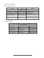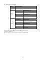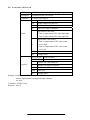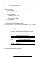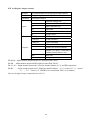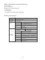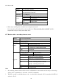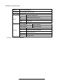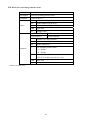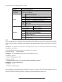
1
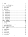
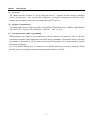
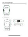
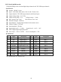
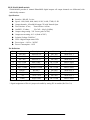
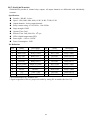
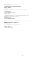
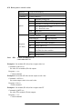
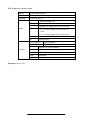
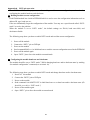
JDAM-9000 Digital series USER'S MANUAL (V1.0) 健昇科技股份有限公司 JS AUTOMATION CORP. 新北市汐止區中興路 100 號 6 樓 6F., No.100, Zhongxing Rd., Xizhi Dist., New Taipei City, Taiwan TEL:+886-2-2647-6936 FAX:+886-2-2647-6940 http://www.automation.com.tw http://www.automation-js.com/ E-mail:[email protected] Contents Chapter 1 Introduction................................................................................................................... 3 1.1 Overview 3 1.2 Module Compatibility 3 1.3 Communication and Programming 3 Chapter 2 About the JDAM DIO Modules 4 2.1 Outline of JDAM DIO modules 4 2.2 Module Dimension 4 2.3 JDAM DIO modules 5 2.4 Block diagram of modules 6 2.5 Wire connection 8 2.6 JDAM specification 10 2.6.1 JDAM-9520 module............................................................................................................... 10 2.6.2 JDAM-9041D module............................................................................................................ 12 2.6.3 JDAM-9042D module............................................................................................................ 13 2.6.4 JDAM-9043D module............................................................................................................ 14 2.6.5 JDAM-9044D module............................................................................................................ 15 2.6.6 JDAM-9050D module............................................................................................................ 16 2.6.7 JDAM-9052D module............................................................................................................ 17 2.6.8 JDAM-9053D module............................................................................................................ 18 2.6.9 JDAM-9060D module............................................................................................................ 19 2.6.10 JDAM-9063D module............................................................................................................ 20 2.6.11 JDAM-9063AD module ......................................................................................................... 21 2.6.12 JDAM-9063BD module ......................................................................................................... 22 2.6.13 JDAM-9065D module............................................................................................................ 23 2.6.14 JDAM-9065AD module ......................................................................................................... 24 2.6.15 JDAM-9065BD module ......................................................................................................... 25 2.6.16 JDAM-9066D module............................................................................................................ 26 2.6.17 JDAM-9067D module............................................................................................................ 27 Chapter 3 Installation ..................................................................................................................... 28 3.1 Set up an JDAM network 28 3.2 JDAM modules 28 3.3 Host computer 28 3.4 Power supply 29 3.5 Communication Wiring 29 3.6 JDAM Utility Software 29 3.7 JDAM Isolated RS-232/RS485 Converter (optional) 29 3.8 Initializing a Brand-New Module 30 3.9 Initialization Procedure 30 3.10 Install a New JDAM to a Existing Network 31 Chapter 4 Command Set ................................................................................................................ 32 4.1 Introduction 32 4.2 Format of JDAM Commands 32 4.3 Response of Commands 33 4.4 Table of Command sets 34 4.5 Reset module 35 4.6 Set brand compatible 36 4.7 Read current brand ID 37 4.8 Set module LED on/off 38 4.9 Read LED control settings 39 4.10 Set Module configuration 40 4.11 Synchronized Sampling 42 1 4.12 Set Digital output channel 43 4.13 Read Digital input counter 45 4.14 Read Configuration 46 4.15 Read Synchronized data 47 4.16 Read reset status 49 4.17 Read digital I/O status 50 4.18 Read firmware version 51 4.19 Read module name 52 4.20 Clear latched digital input 53 4.21 Clear digital input counter 54 4.22 Read latched digital input 55 4.23 Read digital input/output status 56 4.24 Set digital output 57 4.25 Set module name 58 4.26 Host OK 59 4.27 Read module’s watchdog timeout status 59 4.28 Reset module status 60 4.29 Read host watchdog timeout value 61 4.30 Set host watchdog timeout value 62 4.31 Read power-on/safe value 64 4.32 Set power-on/safe value 66 Appendix A INIT*pin operation.......................................................................................................... 67 Appendix B Input counter and input latch......................................................................................... 68 Appendix C Power on/Safe value ........................................................................................................ 69 2 Chapter 1 Introduction 1.1 Overview The JDAM-9000 DIO modules is a set of intelligent sensor to computer interface modules containing built-in microprocessor. They provide data comparison, and digital communication functions. Some modules provide digital I/O lines for controlling relays and TTL devices. 1.2 Module Compatibility The JDAM-9000 series are fully compatible to Advantech® ADAM-4000 series, ADlink® NμDAM-6000 series and ICP® I-7000 series by Command “~AA2X01V” .(Ref. sec. 4.6) 1.3 Communication and Programming JDAM modules can connect to and communicate with all computers and terminals. They use RS-485 transmission standards, and communicate with ASCII format commands. All communications to and from the module are performed in ASCII, which means that JDAM modules can be programmed in virtually any high-level language. Up to 256 JDAM modules may be connected to an RS-485 multi-drop network by using the JDAM RS-485 repeater, extending the maximum communication distance to 4,000 ft. 3 Chapter 2 About the JDAM DIO Modules 2.1 Outline of JDAM DIO modules 2.2 Module Dimension 4 2.3 JDAM DIO modules The JDAM provides a series of digital input or output modules to sense the digital signal or to control the remote devices. JDAM-9520 : Isolated RS-232 to RS-422/485 converter JDAM-9041D : 14-channel isolated digital input module JDAM-9042D: 13-channel isolated digital output module JDAM-9043D: 16 channel digital output module JDAM-9044D : 8-out/ 4-in channel isolated digital I/O module JDAM-9050D : 8-out/ 7-in Digital I/O module JDAM-9052D : 8-channel Isolated digital input module JDAM-9053D : 16-channel digital input module JDAM-9060D : 4-channel isolated digital input and 4 - channel relay output module JDAM-9063D : 8-channel isolated digital inputs and 3 channel relay outputs module JDAM-9063AD : 8-channel isolated digital inputs and 3 channel AC-SSR outputs module JDAM-9063BD : 8-channel isolated digital inputs and 3 channel DC-SSR outputs module JDAM-9065D : 4 channel isolated digital inputs and 5 channel relay outputs JDAM-9065AD : 4 channel isolated digital inputs and 5 channel AC-SSR outputs JDAM-9065BD : 4 channel isolated digital inputs and 5 channel DC-SSR outputs JDAM-9066D : 8 channel Photo-MOS relay outputs JDAM-9067D : 8 channel relay outputs 5 2.4 Block diagram of modules +5V INIT eDAM-8042D JDAM-9042D eDAM-8041D JDAM-9041D +5V +5V LED module D.COM Micro processor DI1 DI0 INIT (EEPROM) Data+ Data- GND DO0 DO1 Micro processor (EEPROM) Data+ Data- RS-485 interface RS-485 interface +5V VS EXT.PWR LED module +5V VS Power supply GND DI13 Power supply DO12 D.COM eDAM-8043D JDAM-9043D LED module eDAM-8044D JDAM-9044D +5V +5V +5V DO0 LED module D.COM DI0 INIT DO1 Micro processor INIT (EEPROM) Micro processor DI3 (EEPROM) RS-485 interface Data+ Data- +5V DO15 +5V VS GND +5V eDAM-8050D JDAM-9050D LED module DI0 Micro processor DI6 LED module INIT Data+ RS-485 interface DataVS DO7 Power supply GND +5V LED module INIT JDAM-9053D DataVS Power supply DI7+ D.GND +5V D.COM DI0 LED module DI1 INIT Data+ RS-485 interface DI6+ eDAM-8060D DI0 Micro processor Power supply DI1- RS-485 interface Data- DI14 DI3 Micro processor (EEPROM) RS-485 interface +5V GND DI1+ Micro processor JDAM-9060D eDAM-8053D (EEPROM) Data+ DI0- +5V +5V GND DI0+ (EEPROM) DO0 VS eDAM-8052D JDAM-9052D +5V +5V +5V +5V (EEPROM) Data+ Data- OUT.COM COIL INIT DO7 Power supply COIL GND Power supply +5V VS DI15 GND 6 Power supply COIL VS EXT.PWR DO0 RS-485 interface COIL Data+ Data- RL1 COM RL1 NO RL2 COM RL2 NO RL3 COM RL3 NC RL3 NO RL4 COM RL4 NC RL4 NO JDAM-9063AD JDAM-9063BD eDAM-8063AD eDAM-8063BD +5V +5V D.COM DI0 LED module D.COM DI0 LED module DI7 INIT Micro processor SSR1+ (EEPROM) Data+ Data- GND INIT SSR1Data+ SSR2+ Data- SSR2+ RS-485 interface SSR2- Power supply SSR1+ (EEPROM) SSR1- RS-485 interface +5V VS DI7 Micro processor SSR2SSR3+ +5V VS SSR3+ GND Power supply SSR3- SSR3- JDAM-9063D eDAM-8063D +5V D.COM DI0 LED module eDAM-8065AD JDAM-9065AD +5V D.COM LED module DI0 DI7 INIT RS-485 interface RL2 COM RL3 COM +5V (EEPROM) Data+ Data- RL2 NO +5V VS GND RL3 NO D.COM LED module DI3 COIL Micro processor RL1 COM INIT RL1 NO DI0 DI3 Micro processor SSR1+ COIL (EEPROM) RS-485 interface RL2 COM RL2 NO Data+ Data- +5V RL5 COM GND RL5 NO SSR5- eDAM-8066D JDAM-9066D LED module RL1NO RL2COM INIT RL2NO INIT Data- Data+ RS-485 interface Data- GND Power supply RL2COM RL2NO RL7COM RS-485 interface +5V +5V VS Micro processor RL1COM RL1NO (EEPROM) (EEPROM) Data+ eDAM-8067D JDAM-9067D +5V RL1COM Micro processor SSR5+ Power supply COIL supply LED module SSR1- RS-485 interface +5V VS Power JDAM-9065D COIL GND eDAM-8065BD +5V +5V VS SSR5- D.COM DI0 (EEPROM) Data- SSR5+ Power supply +5V LED module Data+ SSR1- RS-485 interface JDAM-9065BD JDAM-9065D eDAM-8065D INIT SSR1+ COIL GND Power supply DI3 Micro processor COIL VS RL1 COM RL1 NO COIL Data- COIL (EEPROM) Data+ COIL INIT Micro processor VS RL7COM GND RL7NO 7 Power supply RL7NO eDAM-8520 JDAM-9520 RX RS-232C Interface Auto Baud rate Detector RS-485 RS422 interface Protector TX Power supply VS Data+ Data+ +5V Isolated Power TX+ TXRX+ RX- GND 2.5 Wire connection JDAM-9041D/44D/60D/63D/65D/65AD/65BD TTL/COMS Signal input Dry/Contact Signal input JDAM-9050D/53D Dry/Contact Signal input TTL/COMS Signal input 8 JDAM-9050D/53D Dry/Contact Signal input TTL/COMS Signal input JDAM-9050D JDAM-9043D Open collector output Open collector output JDAM-9042D Open collector output 9 2.6 JDAM specification 2.6.1 JDAM-9520 module JDAM-9520 is an isolated RS-232 to RS-422/RS-485 converter, it converts the RS-232 signal to the RS-422/RS-485 signals. The JDAM-9520 equips a “Auot baud rate detector” inside, it can detect the baud rate and data format and control the direction of the RS-485 network automatically Specifications: Input Interface : standard RS-232 9 pin female D-type connector Output Interface :RS-485, differential, 2 half-duplex wires RS-422, differential, 4 full-duplex wires Max RS-485 network distance : 4000 ft. (1200m) Speed (bps) : auto switching baud rate Isolation voltage : 3000 Vrms Max loading : 128 JDAMs on a RS-485 network Power supply : +10V to +30V, 0.95 W Pin Definitions RS-232 connector (9-pin D-type female) Pin Name Description 1 N.C No used 2 RXD Receiver 3 TXD Transmitter 4 N.C No used 5 GND Ground 6 N.C No used 7 N.C No used 8 N.C No used 9 N.C No used 10 RS-422/485 terminal (10-pin plug-in screw terminal block) Pin Name Description 1 DATA+ RS-485 transmission line, positive 2 DATA- RS-485 transmission line, negative 3 N.C No used 4 TX+ RS-422 transmission line, positive 5 TX- RS-422 transmission line, negative 6 RX+ receiving line, positive 7 RX- receiving line, negative 8 N.C No used 9 +Vs power supply +10V~+30V 10 GND Power GND Connection Between Host and JDAM-9520 HOST PC JDAM9520 eDAM8520 RS-232C Data+ 3 TX Data2 RX 5 GND TX 3 RX 2 5 GND VS GND VS Power supply GND 10Vdc-30Vdc RS-422/RS-485 settings The switch called “S1” inside the module is used to set the JDAM-9520 to be RS-422 or RS-485 operating mode. Pin1 Pin2 Pin3 Pin4 Operating mode off off off off RS-422 on on off RS-485 on 11 2.6.2 JDAM-9041D module JDAM-9041D provides 14 isolated digital input channels and all channels are single-ended with common ground. The isolation voltage is up to 3750 Vrms. Specifications Interface : RS-485, 2 wires Speed : 1200, 2400, 4900, 9600, 19.2K, 38.4K, 57.6K,115.2K Channel numbers : 14 isolated single ended with common source Isolation Voltage: 3750Vrms Logical level 0 : +1V Max. Logical level 1: +4.0V ~ +30V Input impedance: 3K ohms LED: 14 digital input status LED Power input : +10V to +30VDC Power Consumption : 1.2W Pin Definitions Pin Name Description Pin Name Description 1 DI10 Digital input 10+ 11 DI0 Digital input 0+ 2 DI11 Digital input 11+ 12 DI1 Digital input 1+ 3 DI12 Digital input 12+ 13 DI2 Digital input 2+ 4 DI13 Digital input 13+ 14 DI3 Digital input 3+ 5 D.COM Digital COMMON 15 DI4 Digital input 4+ 6 INIT* Initial 16 DI5 Digital input 5+ 7 DATA+ RS-485 + 17 DI6 Digital input 6+ 8 DATA- RS-485 - 18 DI7 Digital input 7+ 9 +Vs +10V~+30V 19 DI8 Digital input 8+ 10 GND Power GND 20 DI9 Digital input 9+ 12 2.6.3 JDAM-9042D module JDAM-9042D provides 13 isolated digital output(open collector) channels and all channels are single-ended with common ground. The isolation voltage is up to 3750 Vrms. Specifications Interface : RS-485, 2 wires Speed : 1200, 2400, 4900, 9600, 19.2K, 38.4K, 57.6K,115.2K Channel numbers: 13 isolated single end with common power Output characteristic: open collector transistor Isolation Voltage: 3750Vrms Max. Load Voltage: +30Vdc Maximum current sink: 100mA LED: 13 digital output status LED Power input : +10V to +30VDC Power Consumption : 1.6W Pin Definitions Pin Name Description Pin Name Description 1 DO 10 Digital output 10+ 11 DO0 Digital output 0+ 2 DO 11 Digital output 11+ 12 DO1 Digital output 1+ 3 DO 12 Digital output 12+ 13 DO2 Digital output 2+ 4 Ext.Pwr Ext. power 14 DO3 Digital output 3+ 5 D.COM Digital COMMON 15 DO4 Digital output 4+ 6 INIT* Initial 16 DO5 Digital output 5+ 7 DATA+ RS-485 + 17 DO6 Digital output 6+ 8 DATA- RS-485 - 18 DO7 Digital output 7+ 9 +Vs +10V~+30V 19 DO8 Digital output 8+ 10 GND Power GND 20 DO9 Digital output 9+ 13 2.6.4 JDAM-9043D module JDAM-9043D provides 16 non-isolated digital output(open collector) channels and all channels are single-ended with common ground. Specifications Interface : RS-485, 2 wires Speed : 1200, 2400, 4900, 9600, 19.2K, 38.4K, 57.6K,115.2K Channel numbers : 16 non-isolated single ended Output characteristic: open collector transistor Max Load voltage: 30 Vdc Maximum current sink:100mA LED: 16 digital output status LED Power input : +10V to +30VDC Power Consumption : 1.2W Pin Definitions Pin Name Description Pin Name Description 1 DO 10 Digital output 10+ 11 DO0 Digital output 0+ 2 DO 11 Digital output 11+ 12 DO1 Digital output 1+ 3 DO 12 Digital output 12+ 13 DO2 Digital output 2+ 4 DO 13 Digital output 13+ 14 DO3 Digital output 3+ 5 DO 14 Digital output 14+ 15 DO4 Digital output 4+ INIT/DO15 INIT* or DO15* 16 DO5 Digital output 5+ 7 DATA+ RS-485 + 17 DO6 Digital output 6+ 8 DATA- RS-485 - 18 DO7 Digital output 7+ 9 +Vs +10V~+30V 19 DO8 Digital output 8+ 10 GND Power GND 20 DO9 Digital output 9+ 6 * : Pin-6 are jumper selectable to INIT* or DO15(Ref. Sec 3.8) 14 2.6.5 JDAM-9044D module JDAM-9044D provides 8 isolated digital output(open collector) channels and 4 isolated digital input channels. All output channels are single-ended with common power. Specifications Interface : RS-485, 2 wires Speed : 1200, 2400, 4900, 9600, 19.2K, 38.4K, 57.6K,115.2K Output channels : 8 isolated output channels Isolation Voltage: 3750Vrms Output characteristic: open collector transistor Max output Load voltage: 30 Vdc Maximum output current sink: 375mA Input channels : 4 isolated input channels with common source Input impedance: 3K ohms Logical level 0 : +1V Max., Logical level 1: +4.0V ~ +30Vdc LED: 12 digital input/output status LED Power input : +10V to +30VDC Power Consumption : 1.8W Pin Definitions Pin Name Description Pin Name Description 1 DI 3 Digital input 3+ 11 Ext.Pwr Ext. power 2 DI 2 Digital input 2+ 12 Out.COM OUT COM 3 DI 1 Digital input 1+ 13 DO0 Digital output 0+ 4 DI 0 Digital input 0+ 14 DO1 Digital output 1+ 5 D.COM Digital COM 15 DO2 Digital output 2+ 6 INIT* Initial 16 DO3 Digital output 3+ 7 DATA+ RS-485 + 17 DO4 Digital output 4+ 8 DATA- RS-485 - 18 DO5 Digital output 5+ 9 +Vs +10V~+30V 19 DO6 Digital output 6+ 10 GND Power GND 20 DO7 Digital output 7+ 15 2.6.6 JDAM-9050D module JDAM-9050D provides 8 non-isolated digital output(open collector) channels and 7 non-isolated digital input channels. All input/output channels are single-ended with common ground. Specifications Interface : RS-485, 2 wires Speed : 1200, 2400, 4900, 9600, 19.2K, 38.4K, 57.6K,115.2K Output channels : 8 non-isolated output channels Output characteristic: open collector transistor Max output Load voltage: 30 Vdc Maximum output current sink: 30mA Input channels : 7 non-isolated input channels Logical level 0 : +1V Max.,Logical level 1: +3.5V ~ +30V LED: 15 digital input/output status LED Power input : +10V to +30VDC Power Consumption : 1.2W Pin Definitions Pin Name Description Pin Name Description 1 DO7 Digital output 7+ 11 DO2 Digital output 2+ 2 DO6 Digital output 6+ 12 DO1 Digital output 1+ 3 DO5 Digital output 5+ 13 DO0 Digital output 0+ 4 DO4 Digital output 4+ 14 DI 0 Digital input 0+ 5 DO3 Digital output 3+ 15 DI 1 Digital input 1+ 6 INIT* Initial 16 DI 2 Digital input 2+ 7 DATA+ RS-485 + 17 DI 3 Digital input 3+ 8 DATA- RS-485 - 18 DI 4 Digital input 4+ 9 +Vs +10V~+30V 19 DI 5 Digital input 5+ 10 GND Power GND 20 DI 6 Digital input 6+ 16 2.6.7 JDAM-9052D module JDAM-9052D provides 6 isolated differential digital input channels and 2 isolated single end with common ground digital input channels. Specifications Interface : RS-485, 2 wires Speed : 1200, 2400, 4900, 9600, 19.2K, 38.4K, 57.6K,115.2K Input channels: 6 isolated differential input channels and 2 single end with common ground input channels Isolation Voltage: 5000Vrms Input impedance : 3K ohms Logical level 0 : +1V Max., Logical level 1: +4.0V ~ +30V LED: 8 digital input status LED Power input : +10V to +30VDC Power Consumption : 0.7W Pin Definitions Pin Name Description Pin Name Description 1 DI5+ Digital input 5+ 11 DI0+ Digital input 0+ 2 DI5- Digital input 5- 12 DI0- Digital input 0- 3 DI6+ Digital input 6+ 13 DI1+ Digital input 1+ 4 D.GND Digital Input GND 14 DI1- Digital input 1- 5 DI7+ Digital input 7+ 15 DI2+ Digital input 2+ 6 INIT* Initial 16 DI2- Digital input 2- 7 DATA+ RS-485 + 17 DI3+ Digital input 3+ 8 DATA- RS-485 - 18 DI3- Digital input 3- 9 +Vs +10V~+30V 19 DI4+ Digital input 4+ 10 GND Power GND 20 DI4- Digital input 4- 17 2.6.8 JDAM-9053D module JDAM-9053D provides 16 non-isolated digital input channels and all channels are single-ended with common ground. Specifications Interface : RS-485, 2 wires Speed : 1200, 2400, 4900, 9600, 19.2K, 38.4K, 57.6K,115.2K Channel numbers : 16 non-isolated single ended Input impedance : 820 ohms Logical level 0 : +2V Max. Logical level 1: +4.0V ~ +30V LED: 16 digital input status LED Power input : +10V to +30VDC Power Consumption : 1.1W Pin Definitions Pin Name Description Pin Name Description 1 DI10 Digital input 10+ 11 DI0 Digital input 0+ 2 DI11 Digital input 11+ 12 DI1 Digital input 1+ 3 DI12 Digital input 12+ 13 DI2 Digital input 2+ 4 DI13 Digital input 13+ 14 DI3 Digital input 3+ 5 DI14 Digital input 14+ 15 DI4 Digital input 4+ 6 INIT*/DI15 INIT or Input 15+ 16 DI5 Digital input 5+ 7 DATA+ RS-485 + 17 DI6 Digital input 6+ 8 DATA- RS-485 - 18 DI7 Digital input 7+ 9 +Vs +10V~+30V 19 DI8 Digital input 8+ 10 GND Power GND 20 DI9 Digital input 9+ * Signal assignment of Pin-6 is jumper selectable by setting JP1 in module (Ref. Sec 3.8) 18 2.6.9 JDAM-9060D module JDAM-9060D provides 4 isolated digital input channels and 4 relay output channels. all relay output channels are differential with individually common . Specifications Interface : RS-485, 2 wires Speed : 1200, 2400, 4900, 9600, 19.2K, 38.4K, 57.6K,115.2K Output channels :4 relay output channels Relay contact rating :0.6A/125Vac, 2A/30Vdc Surge strength: 500V Operate Time: 3mS, Release Time: 2mS, Min Life: 5*105 ops. Input channels : 4 isolated input channels with common source Isolation Voltage: 3750Vrms. Input impedance: 3K ohms Input logical level 0 : +1V Max., logical level 1: +4.0V ~ +30V LED: 8 digital input/output status LED Power input : +10V to +30VDC Power Consumption : 1.8W Pin Definitions Pin Name Description Pin Name Description 1 DI3 Digital input 3+ 11 RL1 NO Relay 1 (NO) 2 DI2 Digital input 2+ 12 RL1 COM Relay 1 COM 3 DI1 Digital input 1+ 13 RL2 NO Relay 2 (NO) 4 DI0 Digital input 0+ 14 RL2 COM Relay 2 COM 5 D.COM Digital COM 15 RL3 NO Relay 3 (NO) 6 INIT* Initial 16 RL3 NC Relay 3 (NC) 7 DATA+ RS-485 + 17 RL3 COM Relay 3 COM 8 DATA- RS-485 - 18 RL4 NO Relay 4 (NO) 9 +Vs +10V~+30V 19 RL4 NC Relay 4 (NC) 10 GND Power GND 20 RL4 COM Relay 4 COM NO: Normal open, NC: Normal Close 19 2.6.10 JDAM-9063D module JDAM-9063D provides 8 isolated digital input channels and 3 relay output channels. All input channels are single ended with common source and all relay output channels are differential with individually common . Specifications Interface : RS-485, 2 wires Speed : 1200, 2400, 4900, 9600, 19.2K, 38.4K, 57.6K,115.2K Output channels :3 relay output channels Surge strength: 4000V Relay contact rating : 5A/250Vac, 5A/30Vdc Operate Time: 6mS Release Time: 3mS, Min Life: 105 ops. Input channels : 8 isolated input channels with common source Isolation Voltage: 3750Vrms Input impedance: 3K ohms Input logical level 0 : +1V Max., logical level 1: +4.0V ~ +30V LED: 11 digital input/output status LED Power input: +10V to +30VDC Power Consumption : 1.8W Pin Definitions Pin Name Description Pin Name Description 1 DI3 Digital input 3+ 11 RL1 NO Relay 1 (NO) 2 DI2 Digital input 2+ 12 RL1 COM Relay 1 COM 3 DI1 Digital input 1+ 13 RL2 NO Relay 2 (NO) 4 DI0 Digital input 0+ 14 RL2 COM Relay 2 COM 5 D.COM Digital Input COM 15 RL3 NO Relay 3 (NO) 6 INIT* Initial 16 RL3 COM Relay 3 COM 7 DATA+ RS-485 + 17 DI7 Digital input 7+ 8 DATA- RS-485 - 18 DI6 Digital input 6+ 9 +Vs +10V~+30V 19 DI5 Digital input 5+ 10 GND Power GND 20 DI4 Digital input 4+ NO: Normal open, NC: Normal Close 20 2.6.11 JDAM-9063AD module JDAM-9063AD provides 8 isolated digital input channels and 3 AC-SSR output channels. Specifications Interface : RS-485, 2 wires Speed : 1200, 2400, 4900, 9600, 19.2K, 38.4K, 57.6K,115.2K Output channels :3 AC-SSR output channels with Normal Open Output voltage rating : 24 to 265 Vrms Output current rating :1.0 Arms, Leakage current: 1.5mArms Min. Operate Time: 1mS, Min. Release Time: 1.5mS Dielectric Strength : 2500Vrms Input channels : 8 isolated input channels with common source Isolation Voltage: 3750Vrms Input impedance: 3K ohms Input logical level 0 : +1V Max., logical level 1: +4.0V ~ +30V LED: 11 digital input/output status LED Power input: +10V to +30VDC Power Consumption : 1.6W Pin Definitions Pin Name Description Pin Name Description 1 DI3 Digital input 3+ 11 SSR1- SSR 1- 2 DI2 Digital input 2+ 12 SSR1+ SSR 1+ 3 DI1 Digital input 1+ 13 SSR2- SSR 2- 4 DI0 Digital input 0+ 14 SSR2+ SSR 2 + 5 D.COM Digital Input COM 15 SSR3- SSR 3- 6 INIT* Initial 16 SSR3+ SSR 3 + 7 DATA+ RS-485 + 17 DI7 Digital input 7+ 8 DATA- RS-485 - 18 DI6 Digital input 6+ 9 +Vs +10V~+30V 19 DI5 Digital input 5+ 10 GND Power GND 20 DI4 Digital input 4+ 21 2.6.12 JDAM-9063BD module JDAM-9063BD provides 8 isolated digital input channels and 3 DC-SSR output channels. All input channels are single ended with common source and all SSR output channels are differential with individually common . Specifications Interface : RS-485, 2 wires Speed : 1200, 2400, 4900, 9600, 19.2K, 38.4K, 57.6K,115.2K Output channels :3 DC-SSR output channels with Normal Open Output voltage rating : 3 to 30 Vdc Output current rating : 1.0 A, Leakage current: 0.1mA Min. Operate Time: 1mS, Min. Release Time: 1mS Dielectric Strength : 2500Vrms Isolation Voltage: 3750Vrms Input channels : 8 isolated input channels with common source Input impedance: 3K ohms Input logical level 0 : +1V Max., logical level 1: +4.0V ~ +30V LED: 11 digital input/output status LED Power input : +10V to +30VDC Power Consumption : 1.6W Pin Definitions Pin Name Description Pin Name Description 1 DI3 Digital input 3+ 11 SSR1- SSR 1- 2 DI2 Digital input 2+ 12 SSR1+ SSR 1+ 3 DI1 Digital input 1+ 13 SSR2- SSR 2- 4 DI0 Digital input 0+ 14 SSR2+ SSR 2 + 5 D.COM Digital Input COM 15 SSR3- SSR 3- 6 INIT* Initial 16 SSR3+ SSR 3 + 7 DATA+ RS-485 + 17 DI7 Digital input 7+ 8 DATA- RS-485 - 18 DI6 Digital input 6+ 9 +Vs +10V~+30V 19 DI5 Digital input 5+ 10 GND Power GND 20 DI4 Digital input 4+ 22 2.6.13 JDAM-9065D module JDAM-9065D provides 4 isolated digital input channels and 5 relay output channels. All input channels are single ended with common source and all relay output channels are differential with individually common . Specifications Interface : RS-485, 2 wires Speed : 1200, 2400, 4900, 9600, 19.2K, 38.4K, 57.6K,115.2K Output channels : 5 relay output channels Relay contact rating :5A/250Vac, 5A/30Vdc Surge strength: 4000V Operate Time: 6mS, Release Time: 3mS, Min Life: 105 ops Input channels : 4 isolated input channels with common source Isolation Voltage: 3750Vrms Input impedance: 3K ohms Input logical level 0: +1V Max., Logical level 1: +4.0V ~ +30V LED: 9 digital input/output status LED Power input : +10V to +30VDC Power Consumption : 2.4W Pin Definitions Pin Name Description Pin Name Description 1 DI3 Digital input 3+ 11 RL1 NO Relay 1 (NO) 2 DI2 Digital input 2+ 12 RL1 COM Relay 1 COM 3 DI1 Digital input 1+ 13 RL2 NO Relay 2 (NO) 4 DI0 Digital input 0+ 14 RL2 COM Relay 2 COM 5 D.COM Digital input COM 15 RL3 NO Relay 3 (NO) 6 INIT* Initial 16 RL3 COM Relay 3 COM 7 DATA+ RS-485 + 17 RL4 NO Relay 4 (NO) 8 DATA- RS-485 - 18 RL4 COM Relay 4 COM 9 +Vs +10V~+30V 19 RL5 NO Relay 5 (NO) 10 GND Power GND 20 RL5 COM Relay 5 COM NO: Normal open, NC: Normal Close 23 2.6.14 JDAM-9065AD module JDAM-9065A provides 4 isolated digital input channels and 5 AC-SSR output channels. All input channels are single ended with common source. Specifications Interface : RS-485, 2 wires Speed : 1200, 2400, 4900, 9600, 19.2K, 38.4K, 57.6K,115.2K Output channels :5 AC-SSR output channels with Normal Open Output voltage rating : 24 to 265 Vrms Dielectric Strength : 2500Vrms Output current rating :1.0 Arms, Leakage current: 1.5mArms Min. Operate Time: 1mS, Min. Release Time: 1.5mS Input channels : 4 isolated input channels with common source Isolation Voltage: 3750Vrms Input impedance: 3K ohms Input logical level 0 : +1V Max., Logical level 1: +4.0V ~ +30V LED: 9 digital input/output status LED Power input : +10V to +30VDC Power Consumption : 1.7W Pin Definitions Pin Name Description Pin Name Description 1 DI3 Digital input 3+ 11 SSR1- SSR 1 - 2 DI2 Digital input 2+ 12 SSR1+ SSR 1 + 3 DI1 Digital input 1+ 13 SSR2- SSR 2 - 4 DI0 Digital input 0+ 14 SSR2+ SSR 2+ 5 D.COM Digital Input COM 15 SSR3- SSR 3- 6 INIT* Initial 16 SSR3+ SSR 3+ 7 DATA+ RS-485 + 17 SSR4- SSR 4- 8 DATA- RS-485 - 18 SSR4+ SSR 4+ 9 +Vs +10V~+30V 19 SSR5- SSR 5- 10 GND Power GND 20 SSR5+ SSR 5+ 24 2.6.15 JDAM-9065BD module JDAM-9065BD provides 4 isolated digital input channels and 5 DC-SSR output channels. Specifications Interface : RS-485, 2 wires Speed : 1200, 2400, 4900, 9600, 19.2K, 38.4K, 57.6K,115.2K Output channels :5 DC-SSR output channels with Normal Open Output voltage rating : 3 to 30 Vdc Output current rating : 1.0 A, Leakage current: 0.1mA Min. Operate Time: 1mS, Min. Release Time: 1mS Dielectric Strength : 2500Vrms Input channels : 4 isolated input channels with common source Isolation Voltage: 3750Vrms Input impedance: 3K ohms Input logical level 0 : +1V Max., Logical level 1: +4.0V ~ +30V LED: 9 digital input/output status LED Power input : +10V to +30VDC Power Consumption : 1.7W Pin Definitions Pin Name Description Pin Name Description 1 DI3 Digital input 3+ 11 SSR1- SSR 1 - 2 DI2 Digital input 2+ 12 SSR1+ SSR 1 + 3 DI1 Digital input 1+ 13 SSR2- SSR 2 - 4 DI0 Digital input 0+ 14 SSR2+ SSR 2+ 5 D.COM Digital Input COM 15 SSR3- SSR 3- 6 INIT* Initial 16 SSR3+ SSR 3+ 7 DATA+ RS-485 + 17 SSR4- SSR 4- 8 DATA- RS-485 - 18 SSR4+ SSR 4+ 9 +Vs +10V~+30V 19 SSR5- SSR 5- 10 GND Power GND 20 SSR5+ SSR 5+ NO: Normal open, NC: Normal Close 25 2.6.16 JDAM-9066D module JDAM-9066D provides 8 channel PhotoMOS digital outputs. all output channels are differential with individually common . Specifications Interface : RS-485, 2 wires Speed : 1200, 2400, 4900, 9600, 19.2K, 38.4K, 57.6K,115.2K Output channels : 8 PotoMOS output CH. with Normal Open Turn-On time: 0.7ms., Turn-Off time: 0.05ms. Out RES.: 23 ohms., I/O CAP. : 0.8pf (f=1Mhz) Output voltage rating : 350 V max (peak AC/DC) Output current rating :0.13 A (Peak AC/DC) Isolation Voltage: 5000VAC LED: 8 digital output status LED Power input : +10V to +30VDC Power Consumption : 1.0W Pin Definitions Pin Name Description Pin Name Description 1 RL6 NO MOS OUT 6 11 RL1 NO MOS OUT 1 2 RL6 COM MOS COM 6 12 RL1 COM MOS COM 1 3 RL7 NO MOS OUT 7 13 RL2 NO MOS OUT 2 4 RL7 COM MOS COM 7 14 RL2 COM MOS COM 2 5 RL8 NO MOS OUT 8 15 RL3 NO MOS OUT 3 6 INIT/ COM8 Initial or COM8 16 RL3 COM MOS COM 3 7 DATA+ RS-485 + 17 RL4 NO MOS OUT 4 8 DATA- RS-485 - 18 RL4 COM MOS COM 4 9 +Vs +10V~+30V 19 RL5 NO MOS OUT 5 10 GND Power GND 20 RL5 COM MOS COM 5 * NO: Normal open, NC: Normal Close. * Signal assignment of Pin-6 is jumper selectable by setting JP1 in module (Ref. Sec 3.8) 26 2.6.17 JDAM-9067D module JDAM-9067D provides 8 channel relay outputs. all output channels are differential with individually common . Specifications Interface : RS-485, 2 wires Speed : 1200, 2400, 4900, 9600, 19.2K, 38.4K, 57.6K,115.2K Output channels : 8 relay output channels Relay contact rating : 0.5A/120Vac, 1.0A/24Vdc Surge strength: 1500V Operate Time: 5mS Release Time: 2mS, Min Life: 105 ops. LED: 8 digital output status LED Power input : +10V to +30VDC Power Consumption : 2.0W Pin Definitions Pin Name Description Pin Name Description 1 RL6 NO Relay OUT 6 11 RL1 NO Relay OUT 1 2 RL6 COM Relay COM 6 12 RL1 COM Relay COM 1 3 RL7 NO Relay OUT 7 13 RL2 NO Relay OUT 2 4 RL7 COM Relay COM 7 14 RL2 COM Relay COM 2 5 RL8 NO Relay OUT 8 15 RL3 NO Relay OUT 3 6 INIT/ COM8 Initial or COM8 16 RL3 COM Relay COM 3 7 DATA+ RS-485 + 17 RL4 NO Relay OUT 4 8 DATA- RS-485 - 18 RL4 COM Relay COM 4 9 +Vs +10V~+30V 19 RL5 NO Relay OUT 5 10 GND Power GND 20 RL5 COM Relay COM 5 * NO: Normal open, NC: Normal Close. * Signal assignment of Pin-6 is jumper selectable by setting JP1 in module (Ref. Sec 3.8) 27 Chapter 3 Installation This chapter provides guidelines to what is needed to set up and install an JDAM network. A quick hookup scheme is provided that lets you configure modules before they are installed in a network. To help you to connect JDAM modules with sensor inputs, several wiring examples are provided. Finally, you will find at the end of this chapter a programming example using the JDAM command set. Be sure to carefully plan the layout and configuration of your network before you start. Guidelines regarding layout are given in Appendix E: RS-485 Network. NOTICE: Except for changing JDAM to other compatible modules, which have on-board switches for their baud rate setting, JDAM modules should not be opened. There is no need to open the JDAM modules: all configuration is done remotely and there are no user serviceable parts are inside. Opening the cover will therefore void the warranty. 3.1 Set up an JDAM network The following list gives an overview of what is needed to setup, install and configure an JDAM environment. A host computer that can output ASCII characters with an RS-232C or RS-485 port. Power supply for the JDAM modules (+10 to +30 VDC ) JDAM Series Utility software 3.2 JDAM modules The JDAM module which you are going to install 3.3 Host computer Any computer or terminal that can output in ASCII format over either RS-232 or RS-485 can be connected as the host computer. When only RS-232 is available, an JDAM-9520 module (RS-232/RS-485 converter) is required to transform the host signals to the correct RS-485 protocol. The converter also provides opto-isolation and transformer-based isolation to protect your equipment. For the ease of use in industrial environments the JDAM modules are designed to accept industry standard +24 VDC unregulated power. Operation is guaranteed when using any power supply between +10 and +30 VDC. Power ripples must be limited to 5 V peak to peak while the voltage in all cases must be maintained between +10 and +30 VDC . All power supply specifications are referenced at module connector. When modules are powered remotely, the effects of line voltage drops must be considered. 28 3.4 Power supply All modules use on-board switching regulators to sustain good efficiency over the 10-30V input range, therefore we can assume that the actual current draw is inversely proportional to the line voltage. The following example shows how to calculate the required current that a power supply should be able to provide. JDAM module 3.5 Communication Wiring We recommend that shielded-twisted-pair cables that comply with the EIA RS-485 standard be used with the JDAM network to reduce interference. JDAM module 3.6 JDAM Utility Software A menu-driven utility program called “DOSJDAM.EXE” for DOS or “WINJDAM.EXE for Windows is provided for JDAM module configuration, monitoring and calibration. It also includes a terminal emulation program that lets you easily communicate through the JDAM command set 3.7 JDAM Isolated RS-232/RS485 Converter (optional) When the host computer or terminal has only a RS-232 port, an JDAM-9520 Isolated RS-232/RS-485/422 converter connected to the host’s RS-232 port is required. This module equips a “Auto baud rate detector” inside, therefore it can detect the baud rate and data format automatically and control the direction of RS-485 precisely 29 3.8 Initializing a Brand-New Module All JDAM modules in a RS-485 network must have an unique address ID. Therefore, to configure the brand-new JDAM before using is necessary Factory default settings: Address ID is 01 Baud rate is 9600 bps Check-sum disable JDAM command sets INIT* State settings: The JDAM I/O modules must be set at INIT* State when you want to change the default settings, such as the ID address, baud rate, check-sum status etc. All JDAM I/O modules have an special pin labeled as INIT*. The module will be in Default State if the INIT* pin is shorted to ground when power ON. Under this state, the default configuration is set as following : Address ID is 00 Baud rate is 9600 bps Check-sum disable JDAM command sets Therefore, the communication between host and the module will can be easily set as the same configuration, the initialization of a module will be possible no matter what configuration is set under operating state. Note: For JDAM-9043D,JDAM-9053D, the pin-6 is used for both DO15 (DI15) and INIT* (default) For JDAM-9066D,JDAM-9067D, the pin-6 is used for both RL8_COM and INIT* (default) When you want to use pin 6 of JDAM-9043D as DO15(DI15) or pin 6 of JDAM-9067D as RL8_COM, you should open the module case to set the JP1. 3.9 Initialization Procedure 1. 2. 3. Connect a brand new JDAM module with the RS-485. Set the module in Default State by shorting the INIT* pin to GND. Refer to Figure 2.1 for detailed wiring. Power on the power supply for JDAM modules. Use the JDAM utility to configure the address ID, baud rate, check-sum status and command sets of the module. JDAM9520 eDAM8520 HOST PC RS-232C TX 3 RX 2 5 GND JDAM I/OI/O module eDAM module RS-485 Data+ 3 TX Data2 RX 5 GND VS GND Data+ Data- INIT VS GND GND Power supply VS 10Vdc-30Vdc 30 3.10 Install a New JDAM to a Existing Network 1. Equipments for Install a New Module 2. A existing JDAM network 3. New JDAM modules. 4. Power supply (+10 to +30 VDC) Installing Procedures 1. Configure the new JDAM module according to the initialization procedure in section 3.8 2. The baud rate and check-sum status of the new module must be identity with the existing RS-485 network. The address ID must not be conflict with other JDAM modules on the network. 3. Power off the JDAM power supply of the existing RS-485 network. 4. Wire the power lines for the new JDAM with the existing network. Be careful about the signal polarity as wiring. 5. Wire the RS-485 data lines for the new JDAM with the existing network. Be careful about the signal polarity as wiring. 6. 7. 8. Wire to the input or output devices. Refer to section 0 for illustrations. Power on the JDAM local power supply. Use the JDAM utility to check entire network. 31 Chapter 4 Command Set 4.1 Introduction The JDAM command is composed by numbers of characteristics, including the leading code, address ID, the variables, the optional check-sum byte, and a carriage return to indicate the end of a command. The host computer can only command only one JDAM module except those synchronized commands with wildcard address command “#**”. The JDAM may or may not give response to the command. The host should check the response to handshake with the modules. 4.2 Format of JDAM Commands Syntax: (Leading code)(Addr)(Command)[Data] <Cksum><CR> Every command begins with a delimiter character. There are four valid characters: a dollar sign $, a pound sign #, a percentage sign % and an at sign @. The delimiter character is followed by a two-character address (hexadecimal) that specifies the target module. The actual two character command follows the address. Depending on the command, an optional data segment follows the command string. An optional two character checksum may be appended to the total string. Every commands is terminated by a carriage return (cr). Conventions Leading Code The first characteristic of the JDAM command, such as %,$,#,~, @, ...etc(1- character) Addr Module’s address ID, the value is in the range of 00 – FF (Hex) 2- character Command Command codes or value of variables Data Data needed by some output command Checksum Checksum in brackets indicate optional parameter, only checksum is enable then this field is required (2- character) <CR> carriage return( 0x0D) Note: 1. all commands should be issued in UPPERCASE characters! 2. There is no spacing between characters. 32 Calculate Checksum: 1. Calculate ASCII sum of all characters of command (or response) string except the character return(cr) 2. Mask the sum of string with 0ffh [Checksum]={(Leading code)+(addr)+(command)+[data]} MOD 0x100 Example: Command string : $012(cr) Sum of string=’$’+’0’+’1’+’2’=24h+30h+31h+32h=B7h The checksum is B7h, and [CHK]=”B7” Command string with checksum=$012B7(cr) Response string : !01400600(cr) Sum of string=’!’+’0’+’1’+’4’+’0’+’0’+’6’+’0’+’0’ =21h+30h+31h+34h+30h+30h+36h+30h+30h=1ACh The checksum is ACh, and [CHK]=”AC” Response string with checksum=!01400600AC(cr) 4.3 Response of Commands The response message depends on JDAM command. The response is also composed with several characteristics, including leading code, variables, and carriage return for ending. There are two kinds of leading code for response message, ”!“ or ”>“ means valid command and ”?“ means invalid. By checking the response message, user can monitor the command is valid or invalid. But under the following conditions, there will have no response message. The specified address ID is not exist. Syntax error. Communication error Some special commands does not have response. 33 4.4 Table of Command sets JDAM Special commands Command Syntax Modules JDAM Special commands Reset module $AARS[CHK](cr) All JDAM modules Set compatible to other brand ~AA2X01V[CHK](cr) All JDAM moudles Read current brand setting ~AA2X02[CHK](cr) All JDAM modules Set module LED on/off !AA2X03IO[CHK](cr) 9041,9042,9043,9044,9050,9052 9053,9060,9063,9065,9066,9067 Read module LED setting !AA2X03[CHK](cr) 9041,9042,9043,9044,9050,9052 9053,9060,9063,9065,9066,9067 General Commands Command Syntax Modules General Commands Set Configuration %AANNTTCCFF[CHK](cr) All JDAM modules Read Configuration $AA2[CHK](cr) All JDAM modules Set Module Name ~AAO[CHK](cr) All JDAM modules Read Module Name $AAM[CHK](cr) All JDAM modules Read Firmware Version $AAF[CHK](cr) All JDAM modules Read reset status $AA5[CHK](cr) All JDAM modules 34 Function Commands Command Syntax Modules Function Commands Synchronized Sampling #**[CHK](cr) 9041,9044,9050,9052,9053,9060,9063,9065 Read Synchronized Data $AA4[CHK](cr) 9041,9044,9050,9052,9053,9060,9063,9065 Digital Output #AAPPDD[CHK](cr) 9042,9043,9044,9050,9060,9063,9065,9066 ,9067 Read Digital Input Counter #AAN[CHK](cr) 9041,9044,9050,9052,9053,9060,9063,9065 Read Digital I/O status $AA6[CHK](cr) 9041,9044,9050,9052,9053,9060,9063,9065 Clear Latched Digital Input $AAC[CHK](cr) 9041,9044,9050,9052,9053,9060,9063,9065 Clear Digital Input Counter $AACN[CHK](cr) 9041,9044,9050,9052,9053,9060,9063,9065 Read Latched Digital Input $AALS[CHK](cr) 9041,9044,9050,9052,9053,9060,9063,9065 Read Digital status @AA[CHK](cr) Input /Output Set Digital Output @AA(data)[CHK](cr) 9041,9044,9050,9052,9053,9060,9063,9065 9042,9043,9044,9050,9060,9063,9065,9066 ,9067 4.5 Reset module Modules: All JDAM modules Description: Reset all existing JDAM modules Command: $AARS[CHK](cr) Syntax: Response: $ Command leading code AA Module address ID (00 to FF) RS Reset command CHK Check sum (cr) Carriage return No response Note: Reset command will reset module to default settings. This command has no response from module Example: Reset module with ID address is 02 Command: $02RS(cr) Response: No response 35 4.6 Set brand compatible Modules: All JDAM modules Description: Set compatible to other brand Command: ~AA2X01V[CHK](cr) Syntax: ~ Command leading code AA Module address ID (00 to FF) 2X JDAM exclusive code 01 Set Compatible command. V Brand ID CHK Check sum (cr) Carriage return !AA[CHK](cr) Valid Command ?AA[CHK](cr) Response: 0= JDAM , 1=ADAM 2=NuDAM, 3=I-7000 Invalid Command ! Delimiter for valid command ? Delimiter for invalid command AA Module address ID CHK Check sum (cr) Carriage return Note: Module will be set to default states after this command issued Example: Set JDAM-9050 module with ID=02 to command .compatible with NuDAM-6050 Command: ~022X012(cr) Response: !02((cr) Example: Set JDAM-9050 module with ID=02 to command .compatible with I-7050 Command: ~022X013(cr) Response: !02(cr) 36 4.7 Read current brand ID Modules: All JDAM modules Description: Read current brand ID setting Command: ~AA2X02[CHK](cr) Syntax: Response: ~ Command leading code AA Module address ID (00 to FF) 2X JDAM exclusive code 02 Read Brand ID com.. CHK Check sum (cr) Carriage return !AAV[CHK](cr) Valid command ?AA[CHK](cr) Invalid command ! Delimiter for valid command ? Delimiter for invalid command AA Module address ID V Brand ID CHK Check sum (cr) Carriage return Example: Read current brand ID of JDAM-9050 module with ID=02 Command: ~022X02(cr) Response: !022((cr) (current module is compatible to NuDAM-6050 37 4.8 Set module LED on/off Modules: All JDAM modules with LED display panel options Description: Set JDAM module LED on/off Command: ~AA2X03IO[CHK](cr) Syntax: ~ Command leading code AA Module address ID (00 to FF) 2X JDAM exclusive code 03 status LED control command. I Input status LED control 1=Turn-on input status LED, when input high 0=Turn-on input status LED, when input low O Output status LED control 1=Turn-on output status LED, when output .active high 0=Turn-on output status LED, when output .active low CHK Check sum (cr) Carriage return !AA[CHK](cr) Valid command ?AA[CHK](cr) Invalid command Response: ! Delimiter for valid command ? Delimiter for invalid command AA Module address ID CHK Check sum (cr) Carriage return Example: Set module with ID=02 to turn-on the LED when relative input channels are high and output channels are active Command: ~022X0311(cr) Response: !02((cr) 38 4.9 Read LED control settings Modules: All JDAM modules with LED display panel options Description: Read status LED control settings Command: ~AA2X03[CHK](cr) Syntax: Response: ~ Command leading code AA Module address ID (00 to FF) 2X JDAM exclusive code 03 Read LED setting command. CHK Check sum (cr) Carriage return !AAIO[CHK](cr) Valid command ?AA[CHK](cr) Invalid command ! Delimiter for valid command ? Delimiter for invalid command AA Module address ID I Input status LED setting (see 4.8) O Output status LED setting (see 4.8) CHK Check sum (cr) Carriage return Example: Read LED control settings of module with ID=02 Command: ~022X03(cr) Response: !0210((cr) Input LED will turn-on when input channels are high and output LED will turn-on when output channels are low 39 4.10 Set Module configuration Modules: All JDAM modules Description: Set module configuration Command: %AANNTTCCFF[CHK](cr) Syntax: % Command leading code AA Module address ID (00 to FF) NN New JDAM address ID (00 to FF) TT Type =40 for DIO module CC Set new baud rate of module (See *) FF Data format (See **) CHK Check sum (cr) Carriage return !AA[CHK](cr) Valid command ?AA[CHK](cr) Invalid command Response: ! Delimiter for valid command ? Delimiter for invalid command AA New Module address ID CHK Check sum (cr) Carriage return * :Baud Rate settings (CC) Code 03 04 05 06 07 08 09 0A Baud rate 120 240 490 960 192 384 576 115 0 0 0 0 00 00 00 200 ** :Data format settings (FF) bit 7 6 5 4 3 2 Bit7: Input counter update direction: 1=Falling edge, 0=rising edge (see 4.13) Bit6:Checksum 1=Enable, 0=disable Bit5~bit0: reserved must be 0 40 1 0 Note: It’s needed to short the INIT* pin to ground while changing baud rate and/or enable/disable checksum (see following examples) Example: Change ID address from 01 to 03 (Assume current baud rate is 9600 and checksum disabled) Command: %0103400600(cr) Response: !03(cr) response new module ID address 03 (change ID address only) Example: Change baud rate from 9600 to 19200(Assume current ID is 03, baud rate is 9600, and checksum disabled). Because that the baud rate is changed from 9600 to 19200, the following procedures should be done before sending this command 1. 2. 3. 4. 5. 6. 7. Power off the module Short INIT* pin to GROUND (see Appendix A) Power on the module send command string Command: %0003400700(cr) Response: !03(cr) response module ID address 03 Power off module Open INIT* pin Power on module again ( Baud rate changed to 19200) Example: Enable checksum(Assume current ID is 03, baud rate is 9600 and checksum disabled). Because that the checksum is changed from disable to enable, the following procedures should be done before sending this command 1. Power off the module 2. Short INIT* pin to GROUND (see Appendix A) 3. Power on the module 4. send command string Command: %0003400640(cr) Response: !03(cr) response module ID address 03 5. Power off module 6. Open INIT* pin 7. Power on module again (checksum enabled) 41 Example: Change baud rate from 9600 to 19200 and enable checksum (Assume current ID is 03, baud rate is 9600 and checksum disabled). Because that both the baud rate and checksum is changed , the following procedures should be done before sending this command 1. Power off the module 2. Short INIT* pin to GROUND (see Appendix A) 3. Power on the module 4. send command string Command: %0003400740(cr) Response: !03(cr) response module ID address 03 5. Power off module 6. Open INIT* pin 7. Power on module again ( Baud rate changed to 19200 and checksum enabled) It is recommended to use the setup utility to configure the module (see section 3.8 and 3.9) 4.11 Synchronized Sampling Modules: For JDAM modules involving digital input channel Description: Synchronize all modules to sample input values and store the values in the module’s register at the same time and use “Read Synchronized Data” command to read the data and process it one by one. Command: Syntax: Response: #**[CHK](cr) # Command leading code ** Synchronized Sampling command CHK Check sum (cr) Carriage return No response Example : command: #**<CR> Synchronized sampling command has no response 42 4.12 Set Digital output channel Modules: For JDAM modules involving digital output channel Description: Set digital output channels Command: #AAPPDD[CHK](cr) Syntax: Response: # Command leading code AA Module address ID (00 to FF) PP Output command type DD Output data CHK Check sum (cr) Carriage return >[CHK](cr) Valid command ?[CHK](cr) Invalid command  Ignored command > Delimiter for valid command ? Delimiter for invalid command ! Delimiter for ignore command(The watchdog timeout status is set) CHK Check sum (cr) Carriage return PP=00,0A – Multi-channel output and DD=low byte data (DO0~DO7) PP=0B – Multi-channel output and DD=high byte data (DO8~DO15) PP=1C,AC – Single channel output and C=low byte channel Number (0~7), and DD=output data PP=BC – Single channel output and C=High byte channel Number (C=0 –channel 8, C=1 –channel 9,……, C=7 – channel 15) , and DD=0 to reset channel, DD=1 to set channel Also see Set digital output command (refer to 4.24 ) 43 Example1: Command: #01000F<cr> AA=01 - address ID PP=00 - Multi-channel output and output to low byte (DO0~DO7) DD=0F – Set DO0~DO3 to “1” and DO4~DO7 to “0” <cr> carriage return Response : >(cr) Example2: Command: #010B20<cr> AA=01 - address ID PP=0B - Multi-channel output and output to high byte (DO8~DO15) DD=20 - Set DO8~DO13 to “0” and DO14~DO15 to “1” <cr> carriage return Response : >(cr) Example3: Command: #011300<cr> AA=01 - address ID PP=13 - Single-channel output and channel number=3 DD=00 - Set DO3 to “0” <cr> carriage return Response : >(cr) Example4: Command: #01B301<cr> AA=01 - address ID PP=13 - Single-channel output and high byte channel number=3 DD=01 - Set DO11 to “1” <cr> carriage return Response : >(cr) 44 4.13 Read Digital input counter Modules: For JDAM modules involving digital input channel Description: Read Digital input counter value Command: #AAN[CHK](cr) Syntax: # Command leading code AA Module address ID (00 to FF) N Digital input channel number (0~F) CHK Check sum (cr) Carriage return !AADDDDD[CHK](cr) Valid command ? AA[CHK](cr) Response: Invalid command ! Delimiter for valid command ? Delimiter for invalid command AA Module address ID DDDDD Counter value in decimal (00000~65535) CHK Check sum (cr) Carriage return Example: Read counter value of channel 5 Command: #025(cr) Response: !0200012(cr) Read counter value of digital input channel 5 is 12 Ref. command: Sec 4.21 $AACN 45 4.14 Read Configuration Modules: For JDAM modules Description: Read module configuration Command: $AA2[CHK](cr) Syntax: Response: $ Command leading code AA Module address ID (00 to FF) 2 Command for reading configuration CHK Check sum (cr) Carriage return !AATTBBFF[CHK](cr) Valid command ?AA[CHK](cr) Invalid command ! Delimiter for valid command ? Delimiter for invalid command AA Module address ID TT Module type(=40 for DIO modules) BB Baud rate FF Configuration value (see *) CHK Check sum (cr) Carriage return *: Configuration value (FF): bit 7: Counter update direction: 0=Falling edge, 1=Rising edge bit 6: Checksum: 1=enable, 0=disable bit 5~bit 3: always 0 bit 2~bit 0: =000 for JDAM-9050 =001 for JDAM- 9060 =010 for JDAM-9052 =011 for JDAM-9053 Example: Read configuration of module with ID address=05 Command: $052(cr) Response: !05400600(cr) Read address ID=05 module configuration 40=DIO module 06=9600 baud rate 00=no checksum, Module number=JDAM-9050 46 Example: Read configuration of module with ID address=06 Command: $062(cr) Response: !06400641(cr) Read address ID=06 module configuration 40=DIO module 06=9600 baud rate 41= checksum enable, Module number=JDAM-9060 4.15 Read Synchronized data Modules: For JDAM modules involving digital input channel Description: Read synchronized data Command: $AA4[CHK](cr) Syntax: Response: (see Note) $ Command leading code AA Module address ID (00 to FF) 4 Command for reading synch. data CHK Check sum (cr) Carriage return !SHHLL00[CHK](cr) Valid command ? AA[CHK](cr) Invalid command ! Delimiter for valid command ? Delimiter for invalid command S Data status, S=1 first read, S=0 been readed HH First data byte(D8~D15) (2 characters) LL Second data byte(D0~D7) (2 characters) 00 Always be 00 CHK Check sum (cr) Carriage return 47 Note: JDAM9041 response :!(Status)(DataInH)(DataInL)00<cr> JDAM9042 response :!(Status)(DataOutH)(DataOutL)00<cr> JDAM9043 response :!(Status)(DataOutH)(DataOutL)00<cr> JDAM9044 response :!(Status)(DataOut)(DataIn)00<cr> JDAM9050 response :!(Status)(DataOut)(DataIn)00<cr> JDAM9052 response :!(Status)(DataIn)0000<cr> JDAM9053 response :!(Status)(DataInH)(DataInL)00<cr> JDAM9060 response :!(Status)(DataOut)(DataIn)00<cr> JDAM9063x response :!(Status)(DataOut)(DataIn)00<cr> JDAM9065x response :!(Status)(DataOut)(DataIn)00<cr> JDAM9066/67 response :!(Status)(DataOut)0000<cr> Example1: Read Synchronized data from JDAM9053 (ID=05) Command: $054(cr) Response: !1097900(cr) Read synchronized data from address ID=05 module S=1 – first read synchronized data=0978 ( D8~15=09H, D0~7=78H) 48 4.16 Read reset status Modules: For JDAM modules Description: Read reset status Command: $AA5[CHK](cr) Syntax: Response: $ Command leading code AA Module address ID (00 to FF) 5 Command for reading reset status CHK Check sum (cr) Carriage return !AAS[CHK](cr) Valid command ?AA[CHK](cr) Invalid command ! Delimiter for valid command ? Delimiter for invalid command S S=1 has been reset, S=0 not been reset CHK Check sum (cr) Carriage return Example1: read digital input data from JDAM9053 (ID=03) Command: $035(cr) Response: !031(cr) Read reset status from address ID=03 module (S=1 module has been reset) 49 4.17 Read digital I/O status Modules: For JDAM DIO modules Description: Read the digital input channel value and readback the digital output channel value. Command: $AA6[CHK](cr) Syntax: Response: (see Note) $ Command leading code AA Module address ID (00 to FF) 6 Command for reading digital I/O status CHK Check sum (cr) Carriage return !FFSS00[CHK](cr) Valid command ?AA[CHK](cr) Invalid command ! Delimiter for valid command ? Delimiter for invalid command FF First byte of I/O status (See **) SS Second byte of I/O status (See **) 00 Always be 00 CHK Check sum (cr) Carriage return Note: JDAM9041 response: !(DataInH)(DataInL)00<CR> JDAM9042 response: !(DataOutH)(DataOutL)00<CR> JDAM9043 response: !(DataOutH)(DataOutL)00<CR> JDAM9044 response: !(DataOut)(DataIn)00<CR> JDAM9050 response: !(DataOut)(DataIn)00<CR> JDAM9052 response: !(DataIn)0000<CR> JDAM9053 response: !(DataInH)(DataInL)00<CR> JDAM9060 response: !(DataOut)(DataIn)00<CR> JDAM9063x response: !(DataOut)(DataIn)00<CR> JDAM9065x response: !(DataOut)(DataIn)00<CR> JDAM9066/67 response: !(DataOut)0000<CR> Example1: read digital input data from JDAM9050 (ID=05) Command: $056(cr) Response: !397900(cr) Read data=3978 Digital output status :DO0~DO7=39H Digital input data : DI0~DI6=78H 50 4.18 Read firmware version Modules: For JDAM DIO modules Description: Read module‘s firmware version. Command: $AAF[CHK](cr) Syntax: Response: (see Note) $ Command leading code AA Module address ID (00 to FF) F Command for reading firmware version. CHK Check sum (cr) Carriage return !AA(data)[CHK](cr) Valid command ?AA[CHK](cr) Invalid command ! Delimiter for valid command ? Delimiter for invalid command AA Module address ID data Module‘s firmware version. CHK Check sum (cr) Carriage return Example: Read firmware version of module address ID=30 Command: $30F<CR> Response: !30A1.04<CR> ! Command is valid., Address ID=30, Firmware Version=A1.04 51 4.19 Read module name Modules: For JDAM DIO modules Description: Read module‘s name Command: $AAM[CHK](cr) Syntax: $ Command leading code AA Module address ID (00 to FF) M Command for reading module’s name CHK Check sum (cr) Carriage return !AA(data)[CHK](cr) Valid command ?AA[CHK](cr) Response: (see Note) Invalid command ! Delimiter for valid command ? Delimiter for invalid command AA Module address ID data Module‘s name CHK Check sum (cr) Carriage return Example: Read module’s name of address ID=30 Command: $30M<CR> Response: !309042<CR> ! Command is valid., Address ID=30, module’s name=9042 52 4.20 Clear latched digital input Modules: For 9041,9044,9050,9052,9053,9060,9063X,9065X Description: Clear latched digital input Command: $AAC[CHK](cr) Syntax: $ Command leading code AA Module address ID (00 to FF) C Command for clearing latched digital input CHK Check sum (cr) Carriage return !AA[CHK](cr) Valid command ?AA[CHK](cr) Invalid command Response: (see Note) ! Delimiter for valid command ? Delimiter for invalid command AA Module address ID CHK Check sum (cr) Carriage return Example: Clear latched input of module address ID=30 Command: $30C<CR> Response: !30<CR> ! Command is valid., Address ID=30, latched inputs are cleared 53 4.21 Clear digital input counter Modules: For 9041,9044,9050,9052,9053,9060,9063X,9065X Description: Clear digital input counter Command: $AACN[CHK](cr) Syntax: Response: (see Note) $ Command leading code AA Module address ID (00 to FF) C Command for clearing digital input counter N Digital counter channel N be cleared CHK Check sum (cr) Carriage return !AA[CHK](cr) Valid command ?AA[CHK](cr) Invalid command ! Delimiter for valid command ? Delimiter for invalid command AA Module address ID CHK Check sum (cr) Carriage return Example: Read channel 2 input counter of module addr. ID=30 Command: #302<CR> Response: !3000123<CR> ! Command is valid., channel 2 input counter value =00123 Example: Clear channel 2 input counter of module addr. ID=30 Command: $30C2<CR> Response: !30<CR> ! Command is valid., channel 2 input counter cleared Example: Read channel 2 input counter of module addr. ID=30 Command: #302<CR> Response: !3000000<CR> ! Command is valid., channel 2 input counter value =00000 54 4.22 Read latched digital input Modules: For 9041,9044,9050,9052,9053,9060,9063X,9065X Description: Read latched digital input Command: $AALS[CHK](cr) Syntax: Response: (see Note)\ $ Command leading code AA Module address ID (00 to FF) L Command for reading latched digital input S =1 latched high status =0 latched low status CHK Check sum (cr) Carriage return !HHLL[CHK](cr) Valid command ?AA[CHK](cr) Invalid command ! Delimiter for valid command ? Delimiter for invalid command HH High byte Latched input status LL Low byte latched input status 00 Always be 00 CHK Check sum (cr) Carriage return Example: Read latched input status of module address ID=30 Command: $30L1<CR> Response: !012300<CR> ! Command is valid., High byte latched status(D8~D15)=01 Low byte latched status(D0~D7)=23 Example: Clear latched input status of module address ID=30 Command: $30C<CR> Response: !30<CR> ! Command is valid., and clear latched input status Example: Read latched input status of module address ID=30 Command: $30L1<CR> Response: !000000<CR> ! Command is valid., High byte latched status(D8~D15)=00 Low byte latched status(D0~D7)=00 55 4.23 Read digital input/output status Modules: For all JDAM DIO modules Description: Read digital input/output status Command: @AA[CHK](cr) Syntax: Response: (see Note)\ $ Command leading code AA Module address ID (00 to FF) CHK Check sum (cr) Carriage return >HHLL[CHK](cr) Valid command ?AA[CHK](cr) Invalid command > Delimiter for valid command ? Delimiter for invalid command HH High byte input/output status(2 characters) LL Low byte input/output status(2 characters) CHK Check sum (cr) Carriage return Example: Read input/output status of module from JDAM-9060 address ID=30 Command: @30<CR> Response: >0203<CR> ! Command is valid., High byte output status(DO1~DO4)=02 Low byte input status(DI1~DI4)=03 Ref. sec. 4.17 notes 56 4.24 Set digital output Modules: For9042,9043,9044,9050,9063X,9065X,9066,9067 Description: Set digital output channel value at specified address. Command: @AA(Data)[CHK](cr) Syntax: $ Command leading code AA Module address ID (00 to FF) Data Data=0~F( 1 character) for 9060 Data=0~7(1 character) for 9063X Data=00~FF(2 characters) for 9044,9050 Data=00~1F(2 characters) for 9065X Data=00~7F(2 characters) for 9066,9067 Data=0000~1FFF (four characters) for 9042 Data=0000~FFFF(four characters) for 9043 CHK Check sum (cr) Carriage return > Valid command [CHK](cr) ?[CHK](cr) Invalid command Response: (see Note)\ ![CHK]<cr Ignore command >* > Delimiter for valid command ? Delimiter for invalid command ! Delimiter for ignore command CHK Check sum (cr) Carriage return *: Ignore command returned, if the module is in host watchdog timeout mode and output is set to safe value *: Also see Set digital output channel command (see sec.4.12) Example: Set output of JDAM 9060 with address ID=30 Command: @306<CR> Set JDAM9060 relay output to 6 (0110) Response: ><CR> > Command is valid., Example: Set output of JDAM 9044 with address ID=30 Command: @3055<CR> Set JDAM9044 output to 55 (01010101) Response: ><CR> > Command is valid., 57 Example: Set output of JDAM 9042 with address ID=30 Command: @300905<CR> Set JDAM842 output to 0905 (0000100000000101 ) Response: ><CR> > Command is valid., Example: Set output of JDAM 9042 with address ID=30 Command: @300905<CR> Set JDAM842 output to 0905 (0000100000000101 ) Response: !<CR> ! Command is ignored, because that the module is in host watchdog timeout state 4.25 Set module name Modules: For all JDAM modules Description: Set new module name. Command: ~AAODD[CHK](cr) Syntax: $ Command leading code AA Module address ID (00 to FF) O Command for setting new name DD Module name, Max. 6 characters CHK Check sum (cr) Response: (see Note)\ Carriage return !AA [CHK](cr) Valid command ?AA[CHK](cr) Invalid command ! Delimiter for valid command ? Delimiter for invalid command AA Module address ID CHK Check sum (cr) Carriage return Example: Set new module name at address ID=30 Command: ~30O4042<CR> Set new name 4042 to the module at address ID=30 Response: !30<CR> ! Command is valid., 58 4.26 Host OK Modules: For all JDAM modules Description: Host send this command to all modules for send the information “Host OK” Command: ~**[CHK](cr) Syntax: Response: ~ Command leading code ** For all modules CHK Check sum (cr) Carriage return No response *: When host watchdog timer is enable, host computer must send this command to all module before timeout otherwise “Host watchdog timer enabled” module‘s output value will go to safety state output value. 4.27 Read module’s watchdog timeout status Modules: For all JDAM modules Description: Read watchdog timeout status Command: ~AA0[CHK](cr) Syntax: Response: ~ Command leading code AA Module address ID (00 to FF) 0 Command for reading timeout status CHK Check sum (cr) Carriage return ! AASS[CHK](cr) Valid command ?AA[CHK](cr) Invalid command ! Delimiter for valid command ? Delimiter for invalid command AA Module address ID SS SS=00 - watchdog timeout is cleared SS=04 - watchdog timeout is set CHK Check sum (cr) Carriage return Note: 1. the watchdog timeout status will be stored in EEPROM of the module and can only be cleared by issuing ~AA1 command (see ~AA1 and ~AA3EVV commands) 2. When the module’s watchdog timeout value is reached, this command will be responded with SS=04 otherwise SS=00 59 4.28 Reset module status Modules: For all JDAM modules Description: Reset watchdog timeout status Command: ~AA1[CHK](cr) Syntax: Response: ~ Command leading code AA Module address ID (00 to FF) 1 Command for resetting watchdog timeout status CHK Check sum (cr) Carriage return ! AA [CHK](cr) Valid command ?AA[CHK](cr) Invalid command ! Delimiter for valid command ? Delimiter for invalid command AA Module address ID CHK Check sum (cr) Carriage return (reference to ~AA3EVV command) 60 4.29 Read host watchdog timeout value Modules: For all JDAM modules Description: Read host watchdog timeout value Command: ~AA2[CHK](cr) Syntax: ~ Command leading code AA Module address ID (00 to FF) 2 Command for reading watchdog timeout value CHK Check sum (cr) Carriage return ! AAEVV[CHK](cr) Valid command ?AA[CHK](cr) Response: Invalid command ! Delimiter for valid command ? Delimiter for invalid command AA Module address ID E Host watchdog enabled status E=1 – Enable E=0 – Disable VV Timeout value in Hex format from 01 to FF=25.5 seconds (one unit is 0.1 sec) CHK Check sum (cr) Carriage return (also see section 4.30) 61 4.30 Set host watchdog timeout value Modules: For all JDAM modules Description: Set host watchdog timeout value Command: ~AA3EVV[CHK](cr) Syntax: ~ Command leading code AA Module address ID (00 to FF) 3 Command for setting watchdog timeout value E 1= enable, 0= disable Host watchdog VV Timeout value (01~FF, each for 0.1 second) CHK Check sum (cr) Response: Carriage return ! AA [CHK](cr) Valid command ?AA[CHK](cr) Invalid command ! Delimiter for valid command ? Delimiter for invalid command AA Module address ID CHK Check sum (cr) Carriage return Note: If host watchdog timer is enabled, the host should send Host OK (see section 4.26) command periodically within Timeout value to refresh the timer, otherwise the module will be forced to safety state (see section 4.32) Example1: Set module (ID=04) to have watchdog timeout value 10.0 seconds and enable host watchdog Command: ~043164<cr> Set watchdog timeout value 10.0 sec and enable host watchdog Response: !04<cr> Valid command Example2: Read watchdog timeout value form module (ID=04) Command: ~042<cr> Read watchdog timeout value Response: !04164 Watchdog timeout value=10.0 seconds, and host watchdog is enabled Example3: Reset watchdog timer Command: ~**<cr> Read host watchdog timer Stop sending any command string to modules for at least 10.0 seconds. The LED on the module will go to flash. The flash LED indicates the host watchdog is timeout and timeout status is set 62 Example4: Read watchdog timeout status Command: ~040<cr> Read module (ID=04) watchdog timeout status Response: !0404<cr> Timeout status is set Example5: Read watchdog timeout value form module (ID=04) Command: ~042<cr> Read watchdog timeout value Response: !04164 Watchdog timeout value=10.0 seconds, and host watchdog is enabled Example6: Reset watchdog timeout status Command: ~041<cr> Reset watchdog timeout status Response: !04<cr> Watchdog timeout is cleared and LED stop flashing, and host watchdog is disabled Example7: Read watchdog timeout status Command: ~040<cr> Read module (ID=04) watchdog timeout status Response: !0400<cr> Timeout status is cleared 63 4.31 Read power-on/safe value Modules: For all JDAM modules Description: Read Power on and safe value Command: ~AA4V[CHK](cr) Syntax: Response: (see Note) Note: ..DD ~ Command leading code AA Module address ID (00 to FF) 4 Command for reading power on and safe value V V=P – Read power on value V=S – Read safe value CHK Check sum (cr) Carriage return ! AADD[CHK](cr) Valid command ?AA[CHK](cr) Invalid command ! Delimiter for valid command ? Delimiter for invalid command AA Module address ID DD DD=XXXX for JDAM9042,9043X DD=XX00 for other modules CHK Check sum (cr) Carriage return - Power on value for V=P - Safe value for V=S Example1: Set module (ID=04) to have output value AA Command: @04AA<cr> Set value AA to module (ID=04) outputs Response: ><cr> > Valid command Example2: Set module (ID=04) current output as safe value Command: ~045S<cr> Set current output value AA as safe value Response: !04<cr> ! Valid command Example3: Set module (ID=04) to have output value FF Command: @04FF<cr> Set value FF to module (ID=04) outputs Response: ><cr> > Valid command 64 Example4: Set module (ID=04) current output as power on value Command: ~045S<cr> Set current output value FF as power on value Response: !04<cr> ! Valid command Example5: Read Power on value Command: ~044P<cr> Read power on value Response: !04FF00<cr> FF=power on value Example6: Read safe value Command: ~044S<cr> Read safe value Response: !045500<cr> 55=safe value 65 4.32 Set power-on/safe value Modules: For all JDAM modules Description: Set current output value as power on or safe value Command: ~AA5V[CHK](cr) Syntax: Response: ~ Command leading code AA Module address ID (00 to FF) 5 Command for setting power on or safe value V V=P – set current output value as power on .value V=S – set current output value as safe value CHK Check sum (cr) Carriage return ! AA [CHK](cr) Valid command ?AA[CHK](cr) Invalid command ! Delimiter for valid command ? Delimiter for valid command AA Module address ID CHK Check sum (cr) Carriage return Examples: See sec.4.31 66 Appendix A INIT*pin operation The “INIT*mode” has two purposes, one for reading module current configuration, and another for configuring the module baud rate and checksum ■ Reading module current configuration Each JDAM module has a built-in EEPROM which is used to store the configuration information such as address ID, type, baud rate etc.. If the user unfurtunally forget the configuration of the module. User may use a special mode called “INIT* mode” to resolve the problem When the module is set to “INIT* mode”, the default settings are ID=00, baud rate=9600, and checksum=disable The following steps show you how to enable INIT* mode and read the current configuration , 1. Power off the module 2. Connect the “INIT*” pin to GND pin 3. 4. 5. 6. Power on the module Send command $002<cr> in 9600 baud rate to read the current configuration stored in the EEPROM Power off the module again Open “INIT*” pin to force the module to normal mode ■ Configuring the module baud rate and checksum The module should be set to “INIT* mode”, While changing baud rate and/or checksum state by sending “Set module configuration” command( see section 4.10). The following steps show you how to enable INIT* mode and change baud rate and/or checksum state 1. Power off the module 2. Connect the “INIT*” pin to GND pin 3. Power on the module 4. Send command %AANNTTCCFF in 9600 baud rate to set baud rate and/or checksum state (ID should be set to 00 in “INIT* mode”) 5. Power off the module again 6. Open “INIT*” pin to force the module to normal mode 67 Appendix B Input counter and input latch Input counter: Each input channel has internal counter used to count the state change (falling edge or rising edge ) of input signal. The counting value can be read and cleared by sending “Read digital input counter” command or “Clear digital input counter command (see section 4.13 and 4.21) Input latch: Each input channel has internal latch which is used to latch the pulse signal from the input. This latched state can be read by sending “Read latched digital input “ command (see section 4.22) and cleared by sending “Clear latched digital input” command (see section 4.20) For example, if the digital input is connected to a key switch. The key switch is a pulse signal. The user may lose the strike information by sending command $AA6. The digital input latch can latch the pulse and ready be read by sending “Read latched digital input “ command. If the latched state=1 means that there is a key strike occurred. 68 Appendix C Power on/Safe value Power on value: Power on value are used to set the module default output value when the module is turned-on or watch dog timeout reset. This function is especially importance in some application where the specified initial output states are required User can set power on value by sending Set power-on/safe value command (see section 4.32) Safe value: Safe value are used to set the module outputs into the specified values when Host watchdog timeout If The host watchdog timer is enabled by sending Set host watchdog timeout value(see section 4.30), the host should send Host OK (see section 4.26) command periodically within Timeout value to refresh the timer, otherwise the module will be forced to safety state (see section 4.32) 69