1
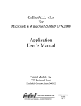
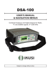
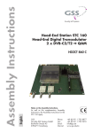
PS DQ 4000
PS DQ 5000
FESSIONAL
PROFESSIONAL
SATELLITE DIGITAL QAM
PR
Grundig SAT Systems
CONTENTS
3
________________________________________________________________________
General
Scope of delivery
Technical data
The DVB twin transmodulator boxes QPSK- QAM PSDQ 4000 and PSDQ 5000
5
Installation
Installing the transmodulator box into the Headend station and connecting it.
6
The Menu Guide
The menu guide at a glance
8
Setup
Setting up the transmodulator box
Adjusting the output levels of the channel lines A and B to each other
LNB frequency
Output channel
Frequency offset
Service settings – Example
Symbol rate
Input frequency (transponder frequency)
QAM modulation value
Saving all settings
Explanation of the »Symbol rate« term
Service (at the end of this user manual)
Channel/frequency tables
2
GENERAL
____________________________________________________________________________
Scope of delivery
1 DVB twin transmodulator box PSDQ 4000 or PSDQ 5000
2 RF connecting cables
1 user manual
1 technical evaluation
1 supplement leaflet (Premiere World)
Technical data
This product conforms with the requirements of the 73/23/EC
and 89/336/EC guidelines of the European Council.
The standards EN 50083-2, EN 50083-2/A1, EN 50083-1, and
EN 60065 required for the CE certification are kept to.
RF output:
PSDQ 4000
Channels:
Frequency range:
Channel norm:
PSDQ 5000
Channels:
Frequency range:
Channel norm:
Output level:
Output impedance:
Frequency detuning of the
output signal:
Connectors:
SAT input:
RF output (modulator):
10-pin connector:
RS 232 socket (9-pin):
950–2150 MHz
1 MHz
35 dBµV....80 dBµV
36 MHz
1....30 Msymb./sec., MCPC/SCPC
S21....S41
306.00 MHz....466.00 MHz
(centre channel frequencies)
PAL CCIR Standard B/G
C21....C69
474.00 MHz....858.00 MHz
(centre channel frequencies)
PAL CCIR Standard G
typ. 90 dBµV
75 Ohm, nominal
±4.00 MHz in 125-kHz steps
2 F-sockets, (screw terminals)
1 IEC socket, female
for all supply voltages and the I 2 C bus
deactivated - without function
Important !
If the GRUNDIG trasporting current module (optional asscessory) is fitted into
this satellite box, the RS 232 socket (serial interface) at the font side of the
satellite box is activated.
Using a PC or notebook, it is possible to upate the software of the satellite box
via this socket.
Subject to technical modifications and errors.
ENGLISH
RF input:
Frequency range:
Frequency spacing:
Level range:
IF bandwidth:
Symbol rate:
3
GENERAL___________________________________________________________________________________
The DVB twin transmodulator boxes QPSK-QAM
PSDQ 4000 and PSDQ 5000
These twin transmodulator boxes are QPSK-QAM modulators which convert
QPSK 1) modulated signals from a satellite into a QAM 2) modulated cable
signal for being distributed via a cable system.
These modulation procedures are layed down by international standards for
the transmission medium (QPSK ➞ satellite signal path, QAM ➞ cable) and
use in an optimum way the available bandwidth.
1) QPSK = Quadrature Phase Shift Keying
2) QAM = Quadrature Amplitude Modulation (QPSK = 4 QAM)
The boxes are controlled via the GRUNDIG Professional Headend station’s
PSU 8 and PSU 12.
Each twin box has two SAT inputs and 1 RF output.
Each box has two channel lines (channel lines A and B).
One channel line consists of a digital SAT tuner, the digital signal processors, and
an analog converter.
The two channel lines of a transmodulator box are indicated as Box A and Box B
in the display of the control unit.
The two input signals are processed according to the box specifications, and then
passed via the RF output socket to the RF output collector of the basic module
carrier.
The common output level (channel lines A and B) of the box can be adjusted
using the mechanic level control (max. – 20 dB) on the RF output collector of the
Headend station.
After switching the headend station on, the software version of the control unit is
briefly shown in the 2-line LC display.
About 5 minutes after the last key is pressed, the display is automatically switched
off, or the software version of the control unit is displayed.
Note:
If desired, the software version of the control unit can also manually be called
up and displayed as follows:
Press and hold down any two buttons on the control unit at the same time
until the following occurs:
– The display turns dark. After several seconds, the software version, e.g.
V.19, appears.
4
INSTALLATION
SAT INPUT B
______________________________________________________________
SAT INPUT A
RS 232
Installing the transmodulator box into the basic module
carrier and connecting it
Caution:
Before fitting or replacing a cassette, it is absolutely necessary
to disconnect the mains plug from the headend station.
1 Undo the fixing screws of the mounting frame, then fit the cassette into a
free slot and refit the fixing screws.
2 Plug the HF input cables into the HF input sockets SAT INPUT A (channel
line A) and SAT INPUT B (channel line B) (see Figure).
3 Reconnect the headend station to the mains supply.
– The cassette is now connected with all necessary supply voltages and data
lines and ready for use.
ENGLISH
Important !
If the GRUNDIG trasporting current module (optional asscessory) is fitted into
this satellite box, the RS 232 socket (serial interface) at the font side of the
satellite box is activated.
Using a PC or notebook, it is possible to upate the software of the satellite box
via this socket.
5
THE MENU GUIDE
____________________________________________________
Note:
You may select the individual menus or menu items by pressing the MODE
key. To go back to the access menu without saving the settings made, press the
MODE key longer than 2 seconds. When in a menu, use the ľ and ı keys
to select the desired setting, and then the + and – keys to change the settings.
Press the M key to save all settings and to return to the access menu.
The following examples show the setup of the transmodulator box PSDQ
4000; on this box, the output channels S21 to S41 can be selected.
ON
BE–Remote
V . 19
please wait . . .
V.19
Software version of the
Headend station’s
control unit
ca. 10 Sec.
MULTI
+/ –
select box
number and
channel line A/B
+/ –
Bx 1A
TWIN–QAM
S21– S41
S21
Bx 1A
TWIN–QAM
LEVEL HF OUT:
O
cut output level of
TWIN-QAM boxes
(channel line A or B)
(0 to –7 dB)
MULTI
MODE
+/ –
enter
LNB frequency
Bx 1A
LNB-Freq. :
f = 10600 MHz
MODE
MULTI
+/ –
select output
channel
(channel centre)
Ł ≥ 2 sec.
fine (offset)
ĵ back
Bx 1A
OUTPUT:
AUSGANGSKANÄLE A/B
S21
(306,00)
OUTPUT CHANNELS A/B
MULTI
MODE
MULTI
MULTI
select
Bx 1A
OUTPUT:
LEVEL CONTROL
Bx 1A
MULTI
OUTPUT:
Modulator on
Bx 1A
OUTPUT:
RANDOM 6875 kBd
+/ –
Modulator off/on
MULTI
MULTI
Bx 1A
SPECTRUM
OUTPUT:
normal
+/ –
Spectrum
normal/
inverse
MODE
Continued on next page.
6
THE MENU GUIDE______________________________________
continued
select
SR
Ł FEC
ĵ Ł
ĵ
+/ –
INPUT:
Bx 1A
SR=27500 FEC=aut
change setting
MODE
+/ –
enter input
frequency
Bx 1A
INPUT:
f=12050
0
MODE
+/ –
adjust QAM
value
Bx 1A
QAM–MODE:
SR=6875
64-QAM
MODE
back to access menu
MODE ≥ 2 sec.
Bx 1A
S21- S41
TWIN–QAM
S21
reset all settings
M
M
ENGLISH
save all settings
7
SETUP
_____________________________________________________________________________________
Setting up the transmodulator box
The transmodulator box is set up exclusivley via the keyboard of the basic
module carrier’s control unit.
The user is guided by means of the two-line display on the control unit.
BE–Remote
V . 19
PROFESSIONAL
1 You may select the following menu items with the MODE key.
–
–
–
–
–
–
–
Box number and channel line (adjust output level of channel line A or B)
LNB frequency
Output channel, frequency offset
Service settings
Symbol rate, FEC
Input frequency (transponder frequency)
QAM modulation value
Note:
The following examples show the setup of the transmodulator box PSDQ
4000; on this box, the output channels S21 to S41 can be selected.
Selecting the box number and the channel line (A or B)
Bx 1A
TWIN-QAM
S21–S41
S21
1 The access menu, e.g. » Bx 1A
2 Use the + or
(A or B).
–
TWIN-QAM « appears in the display.
key to select the desired box number and the channel line
Adjusting the output levels of the channel lines A and B
to each other
Note:
The following adjustment is only necessary if the output level of the two
channel lines A and B of one box differs by ≥ 1dB.
Bx 1A
TWIN-QAM
LEVEL HF OUT:
0
1 Press the MULTI key. The »Bx 1A or Bx 1B
example, appears in the display.
LEVEL HF
OUT:« menu, for
Note:
Check the output level of the channel lines A and B.
2 Using the – key, adjust the higher output level of the respective channel line
A or B to the lower output level of the other channel line in steps from
» 0 to – 7« dB.
Selecting the LNB frequency
Bx 1A
f = 10600MHz
8
LNB-Freq.:
1 Press the MODE key. The »LNB-Freq.:« menu appears in the display.
2 Use the + or – key to select the correct LNB frequency.
SETUP ________________________________________________________________________________________
Selecting the output channel
Bx 1A
OUTPUT:
S21
(306,00)
Bx 1A
OUTPUT:
S21
(306,00)
1 Press the MODE key. The »OUTPUT:« menu appears in the display.
2 Call up the preset output channels of the box by pressing the MULTI key
repeatedly.
Note:
The channels between »S21« and »S41« can be selected.
Please note that the associated frequency shows the channel centre.
The centre channel frequency lies 2.75 MHz above the usual picture carrier
frequency.
A frequency/channel table can be found at the end of this user manaul.
3 Use the + or – key to select the desired output channel.
Adjusting the frequency offset
Attention:
The frequency fine tuning (offset) should only be changed in exceptional
cases, as it requires all TV sets which are connected to the cable system to
match this setting by effecting a corresponding fine tuning correction.
Bx 1A
S21
OUTPUT:
Fine
0
1 Press the ı key until “Fine 0” appears also in the display. Then use the
+ or – key to select a different “Fine” setting.
Press the ľ key to return to the output channel.
The service menu
Bx 1A
OUTPUT:
1 Press the MODE key. The »»OUTPUT: LEVEL CONTROL«« menu appears in
the display.
LEVEL CONTROL
Note:
A power-equivalent RF carrier is generated on the picture carrier of the
respective channel. With that, it is possible to adjust the level of the box with
any commercial measuring receiver tuned to the picture carrier frequency of
the respective channel.
To prevent interferences inside the Headend station and the cable system, the
output level of digital boxes must be cut by about 8 dB with respect to
analog TV channels.
The following example gives detailled information on what is to be observed
and how to proceed.
Example:
2 Connect a commercial analog TV measuring receiver to the RF output socket
»AUSGANG« of the Headend station.
4 Adjust the TV measuring receiver to the selected output channel (e.g. S 21)
of the digital box.
Continued on next page.
ENGLISH
3 Measure the output level of an analog box, and then adjust it to a common
output level (e.g. 100 dBµV).
9
SETUP ________________________________________________________________________________________
5 Check the output level of the digital digital Twin QAM box.
Using the level control situated to the right of the box, you can reduce the
output level of the box by about 8 dB (= 92 dBµV).
Note:
Cutting of the output level effects both channel lines A and B of the digital
Twin QAM box.
Bx 1A
OUTPUT:
6 Press the MULTI key. The » OUTPUT:
control unit’s display.
M odulator« menu appears in the
Modulator on
7 Use the + or
or on again.
Bx 1A
RANDOM
Bx 1A
Spectrum
OUTPUT:
6875 kBd
OUTPUT:
–
key to switch the respective modulator (Output channel) off
8 Press the MULTI key. The » OUTPUT: RANDOM « menu for service functions
appears in the control unit’s display.
– In the second menu row, the associated output symbol rate, e.g.
»6875 kBd « (= 6875 Kilosymbols/sec.), is indicated.
9 Press the MULTI key once again. The »OUTPUT:
appears in the display.
Spectrum « submenu
normal
Note:
The spectrum of the useful signal can be inversed.
An inversion is only necessary in exceptional cases and for certain older
digital cable receivers.
10 Using the + or – key, select the »inverse« or »normal« spectrum setting.
Adjusting the symbol rate »SR«
Bx 1A
SR=27500
INPUT:
FEC=aut
1 Press the MODE key. The »INPUT:« menu appears in the display.
Note:
The symbol rates »SR« of satellite transponders can be found in current
tranponder tables or in various satellite magazines.
2 Use the
value.
ľ
key to select »SR«. Then use the
+ or –
key to set the appropriate
FEC – Forward Error Correction = standardized error protection system for
digital TV broadcasts.
FEC = aut, automatic FEC.
Note:
FEC values can be found in the actual channel tables of the satellite
operators.
If no reception is possible even after entering all parameters, it is also possible
to enter the FEC value manually.
Bx 1A
SR=27500
10
INPUT:
FEC=aut
3 Use the ı k e y t o s e l e c t »FEC«, and then repeatedly press the + or –
key until the picture/sound signal of the desired satellite channel appears
on the picture screen.
– In the second menu row appear one after the other:
– FEC = aut, FEC = 1/2, FEC = 2/3, FEC = 3/4, FEC = 5/6, FEC = 7/8 and
then FEC = aut‚ again.
SETUP ________________________________________________________________________________________
Selecting the input frequency (transponder frequency)
Bx 1A
f=12050
Bx 1A
f=12050
Bx 1A
f=12050
Bx 1A
f=12050
INPUT:
0
INPUT:
...
INPUT:
1 Press the MODE key. The »INPUT:« menu appears in the display.
2 Use the
+ or –
key to set the input frequency.
Note:
If three dots »
« appear in the second menu row, the box is in channel
search mode – please wait.
When the RF reception unit has synchronized with the input signal, a possible
frequency offset with regard to the desired frequency in MHz, e.g. » – 1.8«,
is indicated.
...
3 Using the + or – key, correct the input frequency until the frequency offset
becomes less than 1 MHz.
0
INPUT:
?
Note:
If a question mark » ? « appears in the second menu row, no input signal
has been found. In this case, check the overall configuration of the satellite
system and of the Headend station, as well as the previous settings of the
transmodulator box concerned.
Adjusting the QAM modulation value
Bx 1A
64 – QAM
QAM–MODE
SR=6875
1 Press the MODE key. The »QAM-MODE« menu appears in the display.
– In the second menu row the associated output symbol rate, e.g.
»6875« Kilosymbols/sec., is indcated.
Attention:
For the manual channel search on a connected digital cable receiver, this
must also be set to this value (e.g. »6875« Kilosymbols/sec.).
64 – QAM
Bx 1A
64 – QAM
QAM–MODE
SR=?
QAM–MODE
Error
Attention:
The following restrictions must be observed:
The box can only generate a maximum symbol rate of 7000 Kilosymbols/sec.
A very high input symbol rate can cause an output symbol rate of
> 7000 Kilosymbols/sec.
– In this case, »Error« appears in the second menu row.
The box then must be adjusted to a higher QAM mode value (128 or 256) in
order to adjust the output symbol rate to the admissible value of < 7000
Kilosymbols/sec.
An output symbol rate of above 64-QAM results in very high demands on the
cable network.
Due to noise, runtime and frequency response problems, reception of the
converted output signal may become impossible.
However, it may be expected that all satellite transponders will operate in
the future with symbol rates allowing an output symbol rate of 64-QAM.
Continued on next page.
ENGLISH
Bx 1A
Note:
Normally 64-QAM are transmitted on the cable system.
If a question mark » ? « appears in the second menu row, the transmodulator
box is unable to generate an output signal. In this case, check the overall
configuration of the satellite system and of the Headend station, as well as the
previous settings of the transmodulator box concerned.
11
SETUP ________________________________________________________________________________________
Attention:
Too low input symbol rates may also cause problems.
Certain digital satellite receivers (set-top boxes) allow only for a minimum
specific symbol, or the digital box limits this range to 1000 Kilosymbols/sec..
If you note when setting 64-QAM that the resulting symbol rate is too low for
certain set-top boxes or the transmodulator box, you must set a lower QAM
(ideal is 16-QAM).
The resulting symbol rate then lies in the admissible range again.
Bx 1A
S21–S41
TWIN-QAM
S21
Saving all settings
1 Press the M key to save all new settings.
– The access menu, e.g. »»Bx 1A
TWIN-QAM«, reappears in the display.
Explanation of the »Symbol rate« term
High-value modulation modes such as QPSK or QAM allow for the encryption of
several bits by means of a single physically transmittable and receivable symbol.
The useful data flow contains the picture/sound signal of one satellite transponder and is therefore fixed.
If the modulation degree and thus the number of bits per second is increased, the
symbol rate decreases for a given useful bit rate.
Below you find formulas for the calculation of the output symbol rate »SR (A)«
for a given input signal rate» SR (E)« and »FEC «.
Note:
If no FEC is given in the programme tables, an FEC = 3/4 can be assumed.
256-QAM:
128-QAM:
64-QAM:
032-QAM:
016-QAM:
004-QAM:
SR
SR
SR
SR
SR
SR
(A) = FEC x 1/4 x SR (E)
(A) = FEC x 2/7 x SR (E)
( A ) = FEC x 1/3 x SR ( E )
(A) = FEC x 2/5 x SR (E)
(A) = FEC x 1/2 x SR (E)
(A) = FEC x 1/1 x SR (E)
Example:
Output symbol rate 64-QAM
Input symbol rate SR (E) at 27500 Kilosymbols/sec., FEC = 3/4
SR (A) = FEC 3/4 x 1/3 x SR (E) 27500 Kilosymbols/sec.
= 6875 Kilosymbols/sec..
12
SERVICE
________________________________________________________________________________
Kanal-/Frequenztabelle, Hyperband
Channel/Frequency Table, Hyperband
Kanal
Channel
Frequenz Kanalmitte in MHz
Channel centre frequency in MHz
(Frequenz Bildträger in MHz)
(Picture carrier frequency in MHz)
S 21
306,00
(303,25)
S 22
314,00
(311,25)
S 23
322,00
(319,25)
S 24
330,00
(327,25)
S 25
338,00
(335,25)
S 26
346,00
(343,25)
S 27
354,00
(351,25)
S 28
362,00
(359,25)
S 29
370,00
(367,25)
S 30
378,00
(375,25)
S 31
386,00
(383,25)
S 32
394,00
(391,25)
S 33
402,00
(399,25)
S 34
410,00
(407,25)
S 35
418,00
(415,25)
S 36
426,00
(423,25)
S 37
434,00
(431,25)
S 38
442,00
(439,25)
S 39
450,00
(447,25)
S 40
458,00
(455,25)
S 41
466,00
(463,25)
Continued on next page.
SERVICE _____________________________________________________________________________________
Kanal-/Frequenztabelle, Band IV/ V, CCIR
Channel/Frequency Table, Band IV/ V, CCIR
Kanal
Channel
Frequenz Kanalmitte in MHz
Channel centre frequency in MHz
(Frequenz Bildträger in MHz)
(Picture carrier frequency in MHz)
C 21
474,00
(471,25)
C 22
482,00
(479,25)
C 23
490,00
(487,25)
C 24
498,00
(495,25)
C 25
506,00
(503,25)
C 26
514,00
(511,25)
C 27
522,00
(519,25)
C 28
530,00
(527,25)
C 29
538,00
(535,25)
C 30
546,00
(543,25)
C 31
554,00
(551,25)
C 32
562,00
(559,25)
C 33
570,00
(567,25)
C 34
578,00
(575,25)
C 35
586,00
(583,25)
C 36
594,00
(591,25)
C 37
602,00
(599,25)
C 38
610,00
(607,25)
C 39
618,00
(615,25)
C 40
626,00
(623,25)
C 41
634,00
(631,25)
C 42
642,00
(639,25)
C 43
650,00
(647,25)
C 44
658,00
(655,25)
C 45
666,00
(663,25)
C 46
674,00
(671,25)
C 47
682,00
(679,25)
C 48
690,00
(687,25)
C 49
698,00
(695,25)
C 50
706,00
(703,25)
C 51
714,00
(711,25)
C 52
722,00
(719,25)
C 53
730,00
(727,25)
C 54
738,00
(735,25)
C 55
746,00
(743,25)
C 56
754,00
(751,25)
C 57
762,00
(759,25)
C 58
770,00
(767,25)
C 59
778,00
(775,25)
C 60
786,00
(783,25)
C 61
794,00
(791,25)
C 62
802,00
(799,25)
C 63
810,00
(807,25)
C 64
818,00
(815,25)
C 65
826,00
(823,25)
C 66
834,00
(831,25)
C 67
842,00
(839,25)
C 68
850,00
(847,25)
C 69
858,00
(855,25)
GSS Grundig SAT Systems GmbH • Beuthener Str. 43 • D-90471 Nürnberg • http://www.gss.tv