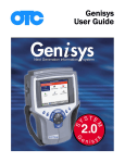
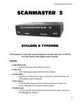
1
Pathfinder 2001 PATHFINDER 2004 USER GUIDE 1 2 IMPORTANT NOTICE IMPORTANT NOTICE SAFETY All Danger, Warning and Important notes must be followed for your safety. These safety messages will be in the following formats: Danger: • Means you may risk possible loss of life Warning: • Means you may risk possible bodily harm Important: • means you risk damage to the vehicle or the tool Notes: are added to provide clarity and helpful tips. These safety messages cover situations SPX is aware of. SPX cannot know, evaluate and advise you as to all of the possible hazards. You must be certain that any conditions or service procedures encountered do not jeopardize your personal safety. COPYRIGHT No part of this manual may be reproduced, stored in a retrieval system or transmitted, in any form or by any means, electronic, mechanical, photocopying, recording, or otherwise, without the prior written permission of SPX. DISCLAIMER All information, illustrations, and specifications contained in this technical instruction manual are based on the latest information available at the time of publication. The right is reserved to make changes at any time without obligation to notify any person or organization of such revisions or changes. Further, SPX shall not be liable for errors contained herein or for incidental or consequential damages (including lost profits) in connection with the furnishing, performance or use of this material. © 2004 SPX Corporation. All rights reserved. i Contents Quick Start . . . . . . . . . . . . . . . . . . . . . . . . . . . . . . . . . . . . . . . . . . . . . . . . . . . . . . . . . . . . . . . 1 Program Software Installation . . . . . . . . . . . . . . . . . . . . . . . . . . . . . . . . . . . . 1 Pathfinder Diagnostics Overview . . . . . . . . . . . . . . . . . . . . . . . . . . . . . . . . 1 More about Diagnostics . . . . . . . . . . . . . . . . . . . . . . . . . . . . . . . . . . . . . . . .1 ...................................................... 2 Quick Startup Diagnostic Functions . . . . . . . . . . . . . . . . . . . . . . . . . . . . . . . . . . . . . . . . . . . . . . . . . . . . 5 Vehicle Description . . . . . . . . . . . . . . . . . . . . . . . . . . . . . . . . . . . . . . . . . . . . . . . 5 New Vehicle Description . . . . . . . . . . . . . . . . . . . . . . . . . . . . . . . . . . . . . . . . . . 6 Saved Vehicle Description . . . . . . . . . . . . . . . . . . . . . . . . . . . . . . . . . . . . . . 6 Select a Vehicle Description . . . . . . . . . . . . . . . . . . . . . . . . . . . . . . . . . . . . 7 Delete a Vehicle Description . . . . . . . . . . . . . . . . . . . . . . . . . . . . . . . . . . . . 7 Repair Trac Fast Fixes ........................................................ 7 .......................................................... 7 Data Stream . . . . . . . . . . . . . . . . . . . . . . . . . . . . . . . . . . . . . . . . . . . . . . . . . . . . . . . . . . . . . . 9 More About Data Stream . . . . . . . . . . . . . . . . . . . . . . . . . . . . . . . . . . . . . . .9 Data Stream Viewing Options . . . . . . . . . . . . . . . . . . . . . . . . . . . . . . . . . . . 10 Integrated Diagnostics - Scan/Gas . . . . . . . . . . . . . . . . . . . . . . . . . . . . . . 10 More about Diagnostics and Scan/Gas Power Control Module Conflict More about conflict . . . . . . . . . . . . . . . . . . . . . . . . . 10 . . . . . . . . . . . . . . . . . . . . . . . . . . . . . . . . . . 12 . . . . . . . . . . . . . . . . . . . . . . . . . . . . . . . . . . . . . . . . . . . . 12 Sensor Lock . . . . . . . . . . . . . . . . . . . . . . . . . . . . . . . . . . . . . . . . . . . . . . . . . . . . . . 13 Custom Data Items . . . . . . . . . . . . . . . . . . . . . . . . . . . . . . . . . . . . . . . . . . . . . . . 13 Record . . . . . . . . . . . . . . . . . . . . . . . . . . . . . . . . . . . . . . . . . . . . . . . . . . . . . . . . . . . . 14 More about Record . . . . . . . . . . . . . . . . . . . . . . . . . . . . . . . . . . . . . . . . . . . . 14 . . . . . . . . . . . . . . . . . . . . . . . . . . 15 Diagnostic Code Triggered Recording To Delete a File File Recording . . . . . . . . . . . . . . . . . . . . . . . . . . . . . . . . . . . . . . . . . . . . . . . 15 . . . . . . . . . . . . . . . . . . . . . . . . . . . . . . . . . . . . . . . . . . . . . . . . . . . . 15 Record Datastream . . . . . . . . . . . . . . . . . . . . . . . . . . . . . . . . . . . . . . . . . . . . 15 Rrecord a Failure Record . . . . . . . . . . . . . . . . . . . . . . . . . . . . . . . . . . . . . . 16 Record Diagnostic Trouble Codes . . . . . . . . . . . . . . . . . . . . . . . . . . . . . . 16 Playback a File . . . . . . . . . . . . . . . . . . . . . . . . . . . . . . . . . . . . . . . . . . . . . . . . . . . 16 Delete a Recorded File . . . . . . . . . . . . . . . . . . . . . . . . . . . . . . . . . . . . . . . . 17 Freeze Frame . . . . . . . . . . . . . . . . . . . . . . . . . . . . . . . . . . . . . . . . . . . . . . . . . . . . . 18 Graphing . . . . . . . . . . . . . . . . . . . . . . . . . . . . . . . . . . . . . . . . . . . . . . . . . . . . . . . . . 18 More about Graphing . . . . . . . . . . . . . . . . . . . . . . . . . . . . . . . . . . . . . . . . . . 18 LED Bar . . . . . . . . . . . . . . . . . . . . . . . . . . . . . . . . . . . . . . . . . . . . . . . . . . . . . . 18 Switch LED . . . . . . . . . . . . . . . . . . . . . . . . . . . . . . . . . . . . . . . . . . . . . . . . . . . 19 Analog meters . . . . . . . . . . . . . . . . . . . . . . . . . . . . . . . . . . . . . . . . . . . . . . . . . 19 To Hide Analog Meters . . . . . . . . . . . . . . . . . . . . . . . . . . . . . . . . . . . . . . . . 19 Zoom Graph . . . . . . . . . . . . . . . . . . . . . . . . . . . . . . . . . . . . . . . . . . . . . . . . . . 20 Print . . . . . . . . . . . . . . . . . . . . . . . . . . . . . . . . . . . . . . . . . . . . . . . . . . . . . . . . . . . . . . . 20 Printer Activation . . . . . . . . . . . . . . . . . . . . . . . . . . . . . . . . . . . . . . . . . . . . . . 20 . . . . . . . . . . . . . . . . . . . . . . . . . . . . . . . . . . . 20 Sensor Display Configuration How to Position Sensors GM Diagnostic State . . . . . . . . . . . . . . . . . . . . . . . . . . . . . . . . . . . . . . . 20 . . . . . . . . . . . . . . . . . . . . . . . . . . . . . . . . . . . . . . . . . . . . . 22 More about Road Test State . . . . . . . . . . . . . . . . . . . . . . . . . . . . . . . . . . . 22 More about Field Service State . . . . . . . . . . . . . . . . . . . . . . . . . . . . . . . . 22 ii More About Back-Up Fuel State . . . . . . . . . . . . . . . . . . . . . . . . . . . . . . . 22 More About ALDL State . . . . . . . . . . . . . . . . . . . . . . . . . . . . . . . . . . . . . . . 22 Diagnostic Code Information . . . . . . . . . . . . . . . . . . . . . . . . . . . . . . . . . . . . . . . . . 23 Read/Current Codes . . . . . . . . . . . . . . . . . . . . . . . . . . . . . . . . . . . . . . . . . . . . . Pending Codes . . . . . . . . . . . . . . . . . . . . . . . . . . . . . . . . . . . . . . . . . . . . . . . . . . . Fail Since Clear Codes . . . . . . . . . . . . . . . . . . . . . . . . . . . . . . . . . . . . . . . . . . . Clear Codes . . . . . . . . . . . . . . . . . . . . . . . . . . . . . . . . . . . . . . . . . . . . . . . . . . . . . . Freeze Frame . . . . . . . . . . . . . . . . . . . . . . . . . . . . . . . . . . . . . . . . . . . . . . . . . . . . . Diagnostic Trouble Code Status . . . . . . . . . . . . . . . . . . . . . . . . . . . . . . . . . Failure Records . . . . . . . . . . . . . . . . . . . . . . . . . . . . . . . . . . . . . . . . . . . . . . . . . . SELF DIAGNOSTICS . . . . . . . . . . . . . . . . . . . . . . . . . . . . . . . . . . . . . . . . . . . . . Key-On, Engine-Off Self-Test . . . . . . . . . . . . . . . . . . . . . . . . . . . . . . . . . . . . More About the KOEO Self-Test 23 23 24 24 24 24 25 25 26 . . . . . . . . . . . . . . . . . . . . . . . . . . . . . . . 26 Key-On, Engine-Off Injector Buzz . . . . . . . . . . . . . . . . . . . . . . . . . . . . . . . 26 Key-On, Engine-Off Output State . . . . . . . . . . . . . . . . . . . . . . . . . . . . . . . . 26 Key-On, Engine-Running Self-Test . . . . . . . . . . . . . . . . . . . . . . . . . . . . . . 27 More About the KOER Self-Test . . . . . . . . . . . . . . . . . . . . . . . . . . . . . . . . 27 27 Key-On, Engine-Running Glow Plug Test . . . . . . . . . . . . . . . . . . . . . . . Key-On, Engine-Running Cylinder Contribution Test . . . . . . . . . . Key-On, Engine-Running Switch Test . . . . . . . . . . . . . . . . . . . . . . . . . . . On Demand Test . . . . . . . . . . . . . . . . . . . . . . . . . . . . . . . . . . . . . . . . . . . . . . . . . . Speed Cable Slack . . . . . . . . . . . . . . . . . . . . . . . . . . . . . . . . . . . . . . . . . . . . . . . Audio Net Test . . . . . . . . . . . . . . . . . . . . . . . . . . . . . . . . . . . . . . . . . . . . . . . . . . . . Accurate Trim . . . . . . . . . . . . . . . . . . . . . . . . . . . . . . . . . . . . . . . . . . . . . . . . . . . . . Pneumatic Test . . . . . . . . . . . . . . . . . . . . . . . . . . . . . . . . . . . . . . . . . . . . . . . . . . . Wiggle Test . . . . . . . . . . . . . . . . . . . . . . . . . . . . . . . . . . . . . . . . . . . . . . . . . . . . . . . Code History . . . . . . . . . . . . . . . . . . . . . . . . . . . . . . . . . . . . . . . . . . . . . . . . . . . . . Trip Counts . . . . . . . . . . . . . . . . . . . . . . . . . . . . . . . . . . . . . . . . . . . . . . . . . . . . . . . 27 27 28 28 28 28 28 29 29 30 Special Tests . . . . . . . . . . . . . . . . . . . . . . . . . . . . . . . . . . . . . . . . . . . . . . . . . . . . . . . . . . . . . 31 Readiness Status . . . . . . . . . . . . . . . . . . . . . . . . . . . . . . . . . . . . . . . . . . . . . . . . 31 More About Readiness Status . . . . . . . . . . . . . . . . . . . . . . . . . . . . . . . . . 31 Drive Cycle . . . . . . . . . . . . . . . . . . . . . . . . . . . . . . . . . . . . . . . . . . . . . . . . . . . . . . . 32 Oxygen Sensor (O2) Test . . . . . . . . . . . . . . . . . . . . . . . . . . . . . . . . . . . . . . . . 32 More About Oxygen Sensor Testing Component Parameters . . . . . . . . . . . . . . . . . . . . . . . . . . . . 32 . . . . . . . . . . . . . . . . . . . . . . . . . . . . . . . . . . . . . . . . . . 33 More About Component Parameters . . . . . . . . . . . . . . . . . . . . . . . . . . . 33 34 OUTPUT CONTROLS . . . . . . . . . . . . . . . . . . . . . . . . . . . . . . . . . . . . . . . . . . . . High Speed Fan On . . . . . . . . . . . . . . . . . . . . . . . . . . . . . . . . . . . . . . . . . . . . . . Low Speed Fan On . . . . . . . . . . . . . . . . . . . . . . . . . . . . . . . . . . . . . . . . . . . . . . . Turn All Outputs On . . . . . . . . . . . . . . . . . . . . . . . . . . . . . . . . . . . . . . . . . . . . . . ENGINE CONTROLS . . . . . . . . . . . . . . . . . . . . . . . . . . . . . . . . . . . . . . . . . . . . . Air Pump Control . . . . . . . . . . . . . . . . . . . . . . . . . . . . . . . . . . . . . . . . . . . . . . . . . Fan On/Off . . . . . . . . . . . . . . . . . . . . . . . . . . . . . . . . . . . . . . . . . . . . . . . . . . . . . . . . Crankshaft Learn . . . . . . . . . . . . . . . . . . . . . . . . . . . . . . . . . . . . . . . . . . . . . . . . . 34 34 35 35 35 36 36 High Fan Control . . . . . . . . . . . . . . . . . . . . . . . . . . . . . . . . . . . . . . . . . . . . . . . . . 36 Low Fan Control . . . . . . . . . . . . . . . . . . . . . . . . . . . . . . . . . . . . . . . . . . . . . . . . . . 36 Idle Air Control Position . . . . . . . . . . . . . . . . . . . . . . . . . . . . . . . . . . . . . . . . . 37 iii Idle Air Control RPM . . . . . . . . . . . . . . . . . . . . . . . . . . . . . . . . . . . . . . . . . . . . . 37 Spark Retard Control . . . . . . . . . . . . . . . . . . . . . . . . . . . . . . . . . . . . . . . . . . . . 37 To Command the Spark Retard . . . . . . . . . . . . . . . . . . . . . . . . . . . . . . . . 37 Starter Inhibit Control . . . . . . . . . . . . . . . . . . . . . . . . . . . . . . . . . . . . . . . . . . . . 37 EVAPORATIVE EMISSIONS CONTROLS . . . . . . . . . . . . . . . . . . . . . . . . 37 Canister Purge Solenoid Control . . . . . . . . . . . . . . . . . . . . . . . . . . . . . . . . 38 To Command the Canister Purge Solenoid . . . . . . . . . . . . . . . . . . . . . 38 . . . . . . . . . . . . . . . . . . . . . . . . . . . . . . . . . . 38 Canister Vent Solenoid Control To Switch the Canister Vent Solenoid . . . . . . . . . . . . . . . . . . . . . . . . . . . 38 Exhaust Gas Recirculation Control . . . . . . . . . . . . . . . . . . . . . . . . . . . . . 38 EGR Vent Solenoid . . . . . . . . . . . . . . . . . . . . . . . . . . . . . . . . . . . . . . . . . . . . . . . 39 Evaporative Service Bay Test . . . . . . . . . . . . . . . . . . . . . . . . . . . . . . . . . . . . 39 To Activate the Evaporative Service Bay Test . . . . . . . . . . . . . . . . . . . 39 FUEL SYSTEM CONTROLS . . . . . . . . . . . . . . . . . . . . . . . . . . . . . . . . . . . . . . 39 Fuel Pump Relay . . . . . . . . . . . . . . . . . . . . . . . . . . . . . . . . . . . . . . . . . . . . . . . . . 39 More About the Fuel Pump Relay Fuel Injector Disable . . . . . . . . . . . . . . . . . . . . . . . . . . . . . . 39 . . . . . . . . . . . . . . . . . . . . . . . . . . . . . . . . . . . . . . . . . . . . . 40 More About Fuel Injector Disable Fuel Closed Loop . . . . . . . . . . . . . . . . . . . . . . . . . . . . . . 40 . . . . . . . . . . . . . . . . . . . . . . . . . . . . . . . . . . . . . . . . . . . . . . . . 40 More About Fuel Closed Loop . . . . . . . . . . . . . . . . . . . . . . . . . . . . . . . . . 40 40 Fuel Trim Reset . . . . . . . . . . . . . . . . . . . . . . . . . . . . . . . . . . . . . . . . . . . . . . . . . . . DIESEL CONTROLS . . . . . . . . . . . . . . . . . . . . . . . . . . . . . . . . . . . . . . . . . . . . . . Boost Control . . . . . . . . . . . . . . . . . . . . . . . . . . . . . . . . . . . . . . . . . . . . . . . . . . . . Engine Shutoff Solenoid . . . . . . . . . . . . . . . . . . . . . . . . . . . . . . . . . . . . . . . . . Fuel Injection Timing Control . . . . . . . . . . . . . . . . . . . . . . . . . . . . . . . . . . . . Glow Plug Relay Control . . . . . . . . . . . . . . . . . . . . . . . . . . . . . . . . . . . . . . . . . ENGINE INDICATOR LAMPS CONTROL . . . . . . . . . . . . . . . . . . . . . . . . Alternator Lamp Control . . . . . . . . . . . . . . . . . . . . . . . . . . . . . . . . . . . . . . . . . Change Oil Lamp Control . . . . . . . . . . . . . . . . . . . . . . . . . . . . . . . . . . . . . . . . Check Gauges Lamp Control . . . . . . . . . . . . . . . . . . . . . . . . . . . . . . . . . . . . Engine Hot Lamp Control . . . . . . . . . . . . . . . . . . . . . . . . . . . . . . . . . . . . . . . . Low Coolant Lamp Control . . . . . . . . . . . . . . . . . . . . . . . . . . . . . . . . . . . . . . MIL Lamp Control . . . . . . . . . . . . . . . . . . . . . . . . . . . . . . . . . . . . . . . . . . . . . . . . Oil Level Lamp Control . . . . . . . . . . . . . . . . . . . . . . . . . . . . . . . . . . . . . . . . . . Oil Pressure Lamp Control . . . . . . . . . . . . . . . . . . . . . . . . . . . . . . . . . . . . . . Service Throttle Soon Lamp Control . . . . . . . . . . . . . . . . . . . . . . . . . . . . TRANSMISSION CONTROLS . . . . . . . . . . . . . . . . . . . . . . . . . . . . . . . . . . . . Pressure Control Solenoid . . . . . . . . . . . . . . . . . . . . . . . . . . . . . . . . . . . . . . Reverse Inhibit Control . . . . . . . . . . . . . . . . . . . . . . . . . . . . . . . . . . . . . . . . . . Torque Converter Clutch Control . . . . . . . . . . . . . . . . . . . . . . . . . . . . . . . . Transmission Gear Control . . . . . . . . . . . . . . . . . . . . . . . . . . . . . . . . . . . . . . 3-2 Shift Solenoid . . . . . . . . . . . . . . . . . . . . . . . . . . . . . . . . . . . . . . . . . . . . . . . . Preset or Reset Adaptive Parameters Control . . . . . . . . . . . . . . . . . . Skip Shift Control . . . . . . . . . . . . . . . . . . . . . . . . . . . . . . . . . . . . . . . . . . . . . . . . TRANSMISSION INDICATOR LAMPS CONTROL . . . . . . . . . . . . . . . 1-4 Shift Lamp Control . . . . . . . . . . . . . . . . . . . . . . . . . . . . . . . . . . . . . . . . . . . 2nd Gear Start Lamp Control 40 41 41 42 42 42 43 43 43 43 43 44 44 44 44 44 45 45 45 46 46 46 46 47 47 . . . . . . . . . . . . . . . . . . . . . . . . . . . . . . . . . . . . 47 iv Shift Lamp Control . . . . . . . . . . . . . . . . . . . . . . . . . . . . . . . . . . . . . . . . . . . . . . . Up-shift Lamp Control . . . . . . . . . . . . . . . . . . . . . . . . . . . . . . . . . . . . . . . . . . . ACCESSORY CONTROLS . . . . . . . . . . . . . . . . . . . . . . . . . . . . . . . . . . . . . . . Air Conditioning Clutch Relay . . . . . . . . . . . . . . . . . . . . . . . . . . . . . . . . . . . Alternator L-Terminal Control . . . . . . . . . . . . . . . . . . . . . . . . . . . . . . . . . . . 47 47 48 48 48 More About the Alternator L-Terminal Cruise Inhibit . . . . . . . . . . . . . . . . . . . . . . . . . . 48 . . . . . . . . . . . . . . . . . . . . . . . . . . . . . . . . . . . . . . . . . . . . . . . . . . . . . 48 More About the Cruise Inhibit Control . . . . . . . . . . . . . . . . . . . . . . . . . . 48 49 Actuator Tests . . . . . . . . . . . . . . . . . . . . . . . . . . . . . . . . . . . . . . . . . . . . . . . . . . . . Idle Air Control . . . . . . . . . . . . . . . . . . . . . . . . . . . . . . . . . . . . . . . . . . . . . . . . . . . Enable/Disable Test . . . . . . . . . . . . . . . . . . . . . . . . . . . . . . . . . . . . . . . . . . . . . . Switch Test . . . . . . . . . . . . . . . . . . . . . . . . . . . . . . . . . . . . . . . . . . . . . . . . . . . . . . . 49 49 50 More about the Switch test . . . . . . . . . . . . . . . . . . . . . . . . . . . . . . . . . . . . 50 To Display All Switches . . . . . . . . . . . . . . . . . . . . . . . . . . . . . . . . . . . . . . . . 50 To Display Shift Level Position . . . . . . . . . . . . . . . . . . . . . . . . . . . . . . . . . 50 Pressure Switches . . . . . . . . . . . . . . . . . . . . . . . . . . . . . . . . . . . . . . . . . . . . . . . 52 Actuator Tests . . . . . . . . . . . . . . . . . . . . . . . . . . . . . . . . . . . . . . . . . . . . . . . . . . . . Clutch Volume Index Test . . . . . . . . . . . . . . . . . . . . . . . . . . . . . . . . . . . . . . . . EMCC Status . . . . . . . . . . . . . . . . . . . . . . . . . . . . . . . . . . . . . . . . . . . . . . . . . . . . . Quick Learn . . . . . . . . . . . . . . . . . . . . . . . . . . . . . . . . . . . . . . . . . . . . . . . . . . . . . . Battery Disconnect . . . . . . . . . . . . . . . . . . . . . . . . . . . . . . . . . . . . . . . . . . . . . . Pinion Factor . . . . . . . . . . . . . . . . . . . . . . . . . . . . . . . . . . . . . . . . . . . . . . . . . . . . . OBD II Trip Status . . . . . . . . . . . . . . . . . . . . . . . . . . . . . . . . . . . . . . . . . . . . . . . . Clutch Tests . . . . . . . . . . . . . . . . . . . . . . . . . . . . . . . . . . . . . . . . . . . . . . . . . . . . . . Before Testing 53 53 54 54 54 54 58 58 . . . . . . . . . . . . . . . . . . . . . . . . . . . . . . . . . . . . . . . . . . . . . . . . . 58 . . . . . . . . . . . . . . . . . . . . . . . . . . . . . . . . . . . . . . . . . . . . . . . . 58 CCD Bus Monitor OTHER TESTS . . . . . . . . . . . . . . . . . . . . . . . . . . . . . . . . . . . . . . . . . . . . . . . . . . . . Minimum Air Idle Speed . . . . . . . . . . . . . . . . . . . . . . . . . . . . . . . . . . . . . . . . . Emission Maintenance Reminder (EMR) Lamp Reset . . . . . . . . . . Set Synchronization Mode . . . . . . . . . . . . . . . . . . . . . . . . . . . . . . . . . . . . . . . Reset Idle Air Control . . . . . . . . . . . . . . . . . . . . . . . . . . . . . . . . . . . . . . . . . . . . Reset Adaptive Fuel . . . . . . . . . . . . . . . . . . . . . . . . . . . . . . . . . . . . . . . . . . . . . Reset Minimum Throttle Position Sensor . . . . . . . . . . . . . . . . . . . . . . . Reset Flexible Fuel Percent . . . . . . . . . . . . . . . . . . . . . . . . . . . . . . . . . . . . . . Enable Door Lock . . . . . . . . . . . . . . . . . . . . . . . . . . . . . . . . . . . . . . . . . . . . . . . . Disable Door Lock . . . . . . . . . . . . . . . . . . . . . . . . . . . . . . . . . . . . . . . . . . . . . . . Module Information . . . . . . . . . . . . . . . . . . . . . . . . . . . . . . . . . . . . . . . . . . . . . . Vehicle Information . . . . . . . . . . . . . . . . . . . . . . . . . . . . . . . . . . . . . . . . . . . . . . Specifications . . . . . . . . . . . . . . . . . . . . . . . . . . . . . . . . . . . . . . . . . . . . . . . . . . . . Related TSBs . . . . . . . . . . . . . . . . . . . . . . . . . . . . . . . . . . . . . . . . . . . . . . . . . . . . . System Type . . . . . . . . . . . . . . . . . . . . . . . . . . . . . . . . . . . . . . . . . . . . . . . . . . . . . . Programmable Read Only Memory Identification . . . . . . . . . . . . . . 59 59 59 59 60 60 60 60 60 61 61 61 61 61 62 62 Pathfinder Quick Path . . . . . . . . . . . . . . . . . . . . . . . . . . . . . . . . . . . . . . . . . . . . . . . . . 63 Repair Trac . . . . . . . . . . . . . . . . . . . . . . . . . . . . . . . . . . . . . . . . . . . . . . . . . . . . . . . 64 Fast Fixes . . . . . . . . . . . . . . . . . . . . . . . . . . . . . . . . . . . . . . . . . . . . . . . . . . . . . . . . . 64 Code Information . . . . . . . . . . . . . . . . . . . . . . . . . . . . . . . . . . . . . . . . . . . . . . . . . 64 More about Failure Statements . . . . . . . . . . . . . . . . . . . . . . . . . . . . . . . . 65 v Symptoms . . . . . . . . . . . . . . . . . . . . . . . . . . . . . . . . . . . . . . . . . . . . . . . . . . . . . . . . Data/Sensor Information . . . . . . . . . . . . . . . . . . . . . . . . . . . . . . . . . . . . . . . . . TSB References . . . . . . . . . . . . . . . . . . . . . . . . . . . . . . . . . . . . . . . . . . . . . . . . . . B.O.B Information . . . . . . . . . . . . . . . . . . . . . . . . . . . . . . . . . . . . . . . . . . . . . . . . Specifications . . . . . . . . . . . . . . . . . . . . . . . . . . . . . . . . . . . . . . . . . . . . . . . . . . . . Component Locations . . . . . . . . . . . . . . . . . . . . . . . . . . . . . . . . . . . . . . . . . . . Reminder Lamp Reset . . . . . . . . . . . . . . . . . . . . . . . . . . . . . . . . . . . . . . . . . . . 66 66 66 66 67 67 68 Appendix. . . . . . . . . . . . . . . . . . . . . . . . . . . . . . . . . . . . . . . . . . . . . . . . . . . . . . . . . . . . . . . . . 69 Vehicle Diagnostic Menus . . . . . . . . . . . . . . . . . . . . . . . . . . . . . . . . . . . . . . . 69 Vehicle Applications . . . . . . . . . . . . . . . . . . . . . . . . . . . . . . . . . . . . . . . . 73 SPX Corporation Limited Warranty . . . . . . . . . . . . . . . . . . . Inside Back Cover Technical Service Inside Back Cover Repair Service Inside Back Cover vi This page is purposely left blank Pathfinder 2004 PROGRAM SOFTWARE INSTALLATION Chapter 1: Quick Start Program Software Installation • If you purchased the Next Generation Information System are automatically and continuously recorded for viewing at any time or to be printed as a document. For more information, refer to “Data Stream” on page 9 tool with Pathfinder 2004, you will find the Pathfinder 2004 program already pre-installed and ready to be used to perform diagnostic analysis on a vehicle. • If you purchased an upgrade to Pathfinder 2004 or any of the other Next Generation Information System programs, you must install the program from the Compact Disk (CD) onto your Next Generation Information System tool. • To install program software revision updates, connect to the SPX Internet web site and download the latest update. Complete instructions for installing program software are located on a separate instruction sheet entitled, “Next Generation Information System Tool Software Installation, p/n 505138” or “How to install program software from a compact flash onto the Next Generation Information System, p/n 511381.” Figure 1.1: Data Stream Display Pathfinder Diagnostics Overview The Pathfinder 2004 Diagnostics program processes vehicle control system data into an easily readable format. The Pathfinder program reads, graphs and records sensor and switch input or output (data stream), reads diagnostic trouble codes and performs special tests. The Pathfinder Quick Path Troubleshooting function provides quick diagnostic tests and troubleshooting data. More about Diagnostics Pathfinder 2004 tests all On-Board Diagnostics Two (OBD II) applications such as GM, Saturn, Ford, Jeep and Chrysler, as well as most Asian and European imports equipped with the OBD II emissions standard system. The Pathfinder 2004 program initiates the diagnostic process by creating a custom menu that lists tests and procedures available for the vehicle description entered into the program. From the custom diagnostic menu, a number of powerful test options can be selected: • Select DATASTREAM to view sensor and switch data stream information communicated from the vehicle computer. The sensors can be arranged on-screen for side-by-side comparison, viewed in a digital, graph, analog meter, or on-screen LED format. Up to 150 frames of data • Select CUSTOM DATA ITEMS to view only the sensors and switches you select. For more information, refer to “Custom Data Items” on page 13 • Select INTEGRATED DIAGNOSTICS - SCAN/GAS to view the sensor and switch datastream side-by-side with exhaust gas datastream ( CO, CO2, HC, O2, NOX AFR). For more information, refer to“Integrated Diagnostics Scan/Gas” on page 10. • Press the RECORD Function key to quickly capture the data stream that occurs before and after the Record key is pressed. The recording can be played back and viewed at any time. For more information, refer to “File Recording” on page 15 • CODE TRIGGERED RECORDING is always active: When a diagnostic trouble code is set, The diagnostic code and the data stream data that occurred before and after the diagnostic code is automatically recorded to a file. The file is placed in the playback folder for viewing at any time. For more information, refer to “Diagnostic Code Triggered Recording” on page 15 • FREEZE FRAME is always available when viewing data stream. Press the left side of the Direction key to instantly “Freeze” the data, then review it frame by frame. For more information, refer to “Freeze Frame” on page 18 • GRAPHING visually displays the sensor data in a continuously updated graph. Data is displayed in a graph format and digital read-out. For more information, refer to “Graphing” on page 18 • Select DIAGNOSTIC CODES to view Diagnostic Trouble Codes set by the vehicle computer. Pathfinder 2004 can also view pending codes to see if a diagnostic code is 1 2 QUICK STARTUP about to be set. And Pathfinder 2004 lists the General Motors OBD II A, B, C, and D diagnostic code designations that help the technician identify the order of importance for repairing diagnostic codes. For more information, refer to “Diagnostic Code Information” on page 23 2 Select Scan Diagnostics from the Application Manager Menu and then press ENTER. Figure 1.3: Application Manager MenuS Figure 1.2: Diagnostic Code Display • Select SPECIAL TESTS to initiate many specific tests for vehicle sensors, control General Motors bi-directional devices and view the immediate sensor reaction onscreen. For more information, refer to “Special Tests” on page 31 3 Select the Pathfinder 2004 diagnostic program, refer to Figure 1.4. The Vehicle Identification screens will appear next. Note: If the Gas 2000 or Gas M-P Gas Analyzer program is installed on the NGIS, the gas program will automatically initialize to be used with Pathfinder. The Gas components used for testing exhaust gas may be installed on the vehicle now. Refer to the Gas analyzer User Manual as required for reference. . • Select PATHFINDER for quick diagnostic tests that are expertly edited from vehicle manufacturer recommended procedures. Pathfinder troubleshooting tests include Diagnostics by Symptom, Code setting Criteria, Wire Colors, Tune-up Specifications, Circuit Descriptions, Circuit Values, Possible Causes and Technical Service Bulletin titles. For more information, refer to “Pathfinder Quick Path” on page 63 • Select REPAIR TRAC from Pathfinder Quick Path to access a databank of repairs for hard-to-diagnose “pattern failures” on vehicles with 50,000 or more miles. For more information, refer to “Repair Trac” on page 7. • Select FAST FIXES for a vehicle specific checklist of most likely and overlooked causes, refer to“Fast Fixes” on page 7 Figure 1.4: Scan Diagnostics Menu Quick Startup The start-up procedure begins immediately when the tool is powered on. After a self-check of the tool, programs from the Application Manager menu may be selected to begin testing. To start the Pathfinder 2004 program, follow these steps: 1 Press the tool power button to activate the tool. The operating system will automatically initialize and an Application Manager menu will appear. Pathfinder 2004 QUICK STARTUP 4 Enter the vehicle description in the program information screens, see Figure 1.5). Place the cursor on the correct response and press ENTER. The number of screens required to describe a vehicle will vary. 1 2 Item 1 Vehicle Description Item 2 Vehicle Cables required Figure 1.6: Vehicle and Cable 6 Attach the Data Link end connector to the vehicle Data Link Connector. Figure 1.5: Vehicle Descriptions 5 When the vehicle description is completed, the correct cable to connect the tool to the vehicle Data Link Connector will be identified, see Figure 1.6. Attach the 25pin connector end to the tool, see Figure 1.7 Note: OBD II vehicles supply power to the scan tool through the 3305-73 cable. When using the 3305-72 OBD I cable, connect the scan tool to a cigarette lighter receptacle or to the vehicle battery for power. This also charges the scan tool internal battery. 1 2 Item 1 Data Link Connector Item 2 Vehicle Adapter Cable Figure 1.7: Connect The Data Link Connector Cable to the Vehicle 7 From the Diagnostic menu, see Figure 1.8, select the tests to perform on the vehicle: • Select DATASTREAM to view sensor and switch data stream information, for more information see “Data Stream” on page 9 • Select CUSTOM DATA ITEMS to view specific sensors and switches and to increase the refresh rate, see “Custom Data Items” on page 13 3 4 QUICK STARTUP • Select INTEGRATED DATASTREAM AND GAS to view the sensor and switch datastream side-by-side with exhaust gas datastream ( CO, CO2, HC, O2, NOX AFR). For more information, see “Integrated Diagnostics - Scan/Gas” on page 10. • select DIAGNOSTIC CODES to view diagnostic trouble codes set by the vehicle computer, for more information see “Diagnostic Code Information” on page 23 • select PATHFINDER for quick diagnostic tests that are expertly edited from vehicle manufacturer recommended procedures, for more information see “Pathfinder Quick Path” on page 63 • select SPECIAL TESTS to initiate specific tests for vehicle sensors, for more information see “Special Tests” on page 31 • select VEHICLE INFORMATION to view specifications provided by the vehicle computer and Pathfinder Quick Path, for more information see “Vehicle Information” on page 61 Note: Some vehicles are not equipped with all of the capabilities Pathfinder 2004 is able to test or activate, all menu choices illustrated will not be applicable for all vehicles. Only those menu choices applicable to the vehicle will be displayed on the Diagnostic Menu. Figure 1.8: Diagnostic Menu Pathfinder 2004 VEHICLE DESCRIPTION Chapter 2: Diagnostic Functions Vehicle Description Vehicle description is required for the Pathfinder 2004 program to create a custom menu that lists the tests and procedures available. The required description process to enter a new vehicle often requires several steps. Pathfinder 2004 speeds this process by storing up to 25 vehicle descriptions in files that you can re- Figure 2.1: Vehicle Description Overview use to re-enter a vehicle description. Simply select the saved description file and press Enter. Refer to Figure 2.1 to view a “snapshot” of typical vehicle identification screens. Vehicle Description steps are described in “New Vehicle Description” on page 6 and demonstrated in “Quick Startup” on page 2. 5 6 NEW VEHICLE DESCRIPTION New Vehicle Description New Vehicle description lists the classification required to identify a vehicle for testing. As a vehicle is identified, the classification path selected is displayed at the top of the screen. When all vehicle classifications are determined, the cables required to connect the test unit to the vehicle are displayed at the bottom of the screen. To save the vehicle identification to a file, follow these steps: 1 Press the REUSE Function key twice when the entire vehicle description is entered. To identify a new vehicle, follow these steps: 1 Select a Vehicle Manufacturer, press ENTER. 2 Select from each of the vehicle classification screens that follow until the vehicle is fully identified. 3 View the vehicle adapter cables required for connecting the test unit to the vehicle. 1 Item 1 Reuse Figure 2.3: Vehicle/Cable Description 2 Press the SAVE Function key to save the vehicle description to memory. Figure 2.2: Vehicle Description Saved Vehicle Description New vehicle information entered into the program may be saved and then selected for same vehicle testing. As many as 25 vehicle classification descriptions may be saved to memory for later use. 2 3 Item 1 Vehicle Description Item 2 Save File Item 3 Delete File Figure 2.4: Reuse List 1 Pathfinder 2004 REPAIR TRAC Select a Vehicle Description To Access Repair Trac or Fast Fix, follow these steps: To select a saved vehicle identification file, follow these steps: 1 Select Repair Trac or Fast Fix from Repair Information on the Application Manager Main Menu, see Figure 2.5 or from Pathfinder “Quickpath,” see Figure 2.6 1 Press the REUSE Function key, see Figure 2.3. 2 Select the vehicle to reuse from the list, see Figure 2.4, press ENTER Delete a Vehicle Description To delete a vehicle description, follow these steps: 1 Select the file to be deleted with the Command Bar, see Figure 2.4. 2 Press the DELETE Function key. Repair Trac Repair Trac is a databank of repairs for those hard-todiagnose “pattern failures” on vehicles with 50,000 or more miles. The Repair Trac databank is accessible at all times from the Application Manager Main Menu and accessible in Pathfinder Quickpath in diagnostic programs such as Pathfinder 2004. Figure 2.5: Application Manager Main Menu Repair Trac Note: If Repair Trac or Fast Fixes are accessed through Pathfinder Quickpath the vehicle classification information entered for the diagnostic program is used, Repair Trac or Fast Fixes for the vehicle will appear immediately. Fast Fixes Fast Fixes are a vehicle-specific diagnostic checklist of the most likely fixes or possible overlooked causes of common problems for the vehicle-identified vehicle. Figure 2.6: Pathfinder Quickpath Repair Trac or Fast Fixex 2 Select from each of the vehicle classification screens, see Figure 2.7 until the vehicle is fully identified. Select the vehicle Year > Make > Model >Engine > System > 7 8 FAST FIXES Symptom. If selection is made from Pathfinder, Repair Trac or Fast Fixes will use the vehicle data entered for Pathfinder. Note: The RT Code located on the Repair Trac Problems and Fixes screen is a Repair Trac Code (RT) only. The RT is not a part of the OBD II or vehicle manufacturer Diagnostic Trouble Codes (DTC). Figure 2.7: Repair Trac or Fast Fixes Selection Pathfinder 2004 FAST FIXES Data Stream Data Stream is the electrical signal sent between the vehicle computer and the vehicle sensors or switches. The data is converted and displayed in a readable format for the repair technician. Figure 2.8: Data Stream Overview More About Data Stream The data stream function activates a pre-selected group of essential sensors and places them at the top of the display for immediate reference. The remaining sensors and switches detected on the vehicle are listed in alphabetical order. Note: Some 2001 and newer vehicles report switches in the data stream that are not installed. Usually the false data is obvious such as reporting a 4-wheel drive switch on a automobile, and the switch always stays in the Off position. If a switch does not turn On or seems out of place, verify that the vehicle is actually equipped with the switch. To view data stream, follow this path: All Vehicles > Diagnostic Menu > Data Stream 9 10 DATA STREAM VIEWING OPTIONS Data Stream Viewing Options 2 From the Diagnostic Menu, Click Integrated Diagnostics and Scan/Gas. When viewing data stream, a number of options are available that permit data review or amplification: • Integrated Diagnostics and Scan/Gas,see page 10 • Power Control Module (PCM) conflict to view conflicting PCM data, see page 12 • Record data, see page 14 • “Zoom” to increase the viewable data window, see page 20 • Digital data, graph, on-screen LED or analog meters display to visually enhance data, see page 18 • Display Configuration to enable sensor comparison, see page 18 and page 20 • Select Custom Data Items to view specific sensors and switches and to increase the refresh rate, see page 13 • Printing to capture data to paper, see page 20.Integrated Datastream and Gas Integrated Diagnostics Scan/Gas Integrated Diagnostics - Scan/Gas views the sensor and switch datastream side-by-side with exhaust gas datastream ( CO, CO2, HC, O2, NOX AFR) More about Diagnostics and Scan/Gas The Gas 2000 or Gas M-P program must be activated with the Smart Card to view the Diagnostics and Scan/Gas function. If the Gas program was not purchased, the Diagnostics and Scan/Gas menu choice will not appear. To View Diagnostics and Scan/Gass , follow these steps: 1 Connect the Gas measurement hardware to the vehicle, refer to the Gas program Users Manual for detailed steps. Figure 2.9: Integrated Diagnostics and Scan/Gas Pathfinder 2004 INTEGRATED DIAGNOSTICS - SCAN/GAS 3 Select the data group for viewing. The Gas program will automatically begin by “zeroing” the Gas Sampling device. Remove the device from the vehicle exhaust to permit intake of fresh air. Figure 2.10: Gas “zero” procedure begins 4 Press the F1-OK button to see the Data and Gas display. Figure 2.11: Gas and Data Display 5 When the Gas program has finished zeroing the device, Shift the Gas data to match it to the vehicle datastream. Note: The exhaust gas produced in the engine at the moment the data sensors read data will not be measured until 9 to 14 seconds later because of the length of the vehicle exhaust system. Shifting the Gas data allow a “match-up” of the engine data with the Gas data 6 “Snap” the throttle open 2 or 3 times to set a full rich condition, count the number of seconds for the HC gas value to show the rich condition. 11 12 POWER CONTROL MODULE CONFLICT 7 Click the More button, and click Gas Options. , Figure 2.14: Data Shift lined up Figure 2.12: Gas Options 8 The Gas Correlation Time Shift screen will appear. Set the shift by pressing the Up or Down arrow to enter the number of seconds to shift the data (10 to 12 seconds is average). Click the F1 (OK) button to view the data with the data shift. 9 Notice in Figure 2.14 the three “snaps” of the throttle align with the same three peaks in the gas data. This indicates that a time shift offset of 10 seconds is correct for this vehicle. Power Control Module Conflict A Power Control Module (PCM) conflict occurs in OBD II generic systems when two, or more, PCMs are reporting conflicting data for the same sensor; for example, RPM. More about conflict When two or more PCMs are reporting conflicting data for the same sensor the data will displayed in a red color. View the Conflict report to determine which PCM may be reporting bad data. Figure 2.13: Shift Data Pathfinder 2004 SENSOR LOCK To View PCM Conflict Report, follow these steps: 1 If the sensor is displayed in a red color, Click F4 More > Conflict. 1 Sensor Lock A sensor may be locked to permit data recording of the locked sensor’s data when it is not displayed onscreen. To lock a sensor, follow these steps: 1 Place the cursor on the sensor and press ENTER. A “Locked” icon will appear to the left of the sensor. Item 1 Sensor displayed in red Figure 2.15: PCM Conflict If the data value in the Conflict Report is close there is no need for concern, the conflict is most likely due to a timing difference between the PCMs when they report data. If there is a large difference in the data value, suspect a broken wire or a PCM fault. Figure 2.17: Sensor Lock 2 To remove the lock, place the cursor on the sensor again and press ENTER. 1 Custom Data Items Sensors and switches may be locked to permit viewing and recording of only the locked sensors and switches. Viewing fewer sensors also increases the refresh rate due to fewer items monitored. To setup Custom Data Items, follow these steps: Item 1 Conflicting sensor data Figure 2.16: PCM Report 13 14 RECORD 1 Select Custom Data Items from the Diagnostic Menu. Figure 2.21: Custom Data Screen Figure 2.18: Diagnostic Menu 2 Select the Disgnostic Data Group required. Record The Record function continuously and automatically creates a record of the sensor or switch data. This data can be viewed “real” time in a graph or up to 150 frames of data can be recorded and stored in a file for detailed examination at a later time. More about Record Three methods are available to capture data or sensor information: • Diagnostic Code Triggered Recording – When a Figure 2.19: Diagnostic Data Group 3 Select the sensors for viewing by moving the cursor to highlight the sensors required, Press ENTER to select (press ENTER to deselect, if required). diagnostic trouble code is set, data stream data that occurred before and after the diagnostic code is automatically recorded to a file. The file is automatically placed in the playback folder for viewing at any time. • Record and Playback – Press the RECORD key to capture up to 150 frames of sensor data that occurred before and after the trigger was pressed. A frame numbered “0” marks when the RECORD key is pressed. the The data is automatically recorded to a file and placed in the playback folder for viewing at any time. • Freeze Frame – Freeze Frame is always available when viewing data stream. Press the left cursor to instantly “Freeze” the data, then review it frame by frame. Figure 2.20: Sensors check list 4 Press F4, View Data. Pathfinder 2004 DIAGNOSTIC CODE TRIGGERED Diagnostic Code Triggered Recording File Recording The Diagnostic Code Triggered record function is always active in data monitor. Whenever a diagnostic code is set in the vehicle computer, the record function will automatically capture the diagnostic code and the data that occurred at the moment the diagnostic code was set, plus it will record data that occurred before and after the diagnostic code was set. The recorded data is automatically saved to a file and stored in the playback folder. A diagnostic code data file can be accessed from the playback file and reviewed at any time. Record Datastream Press the RECORD Function key to instantly create a file. A frame will be marked with the number zero. 74 frames of data before the zero marker (identified with a negative number) and 75 frames of data after the zero marker will be captured and placed in a file in the Playback folder. To view a Triggered Recording, Follow these steps: 1 Press the MENU key to return to the Application Manager Menu. 2 Select Playback, and then press ENTER. 3 Select the file to view, and then press ENTER. 4 Press the left or right side of the Direction key to view each frame in sequence. 5 Press EXIT to return to the Pathfinder program. Figure 2.23: Record datastream Optional: Continue viewing live data or press MENU to return to the Application Manager Menu to playback the file. Figure 2.22: Events to Playback To Delete a File Select the event file and then press the DELETE Function key, see Figure 2.22. 15 16 PLAYBACK A FILE Rrecord a Failure Record Playback a File Select the Failure Record and press the SAVE Function Key to instantly create a file . To playback, follow these steps 1 If playback is desired: Select Playback, and then press ENTER. 2 Select a file from the list to view, and then press ENTER. Figure 2.24: Save a Failure Record Record Diagnostic Trouble Codes Press the SAVE Function key to instantly create a file for the Diagnostic Trouble Codes generated for a vehicle. Figure 2.26: List of Events for Playback 3 Press the left or right side of the Direction key to view each frame in sequence. The vertical ‘cross-hair” in the graph will move to visually indicate the exact frame for a particular point in time, see Figure 2.27 on page 17. The graphed data will be magnified when the cross-hair moves across each frame. 4 You can also scroll up or down in the recorded file to select different data items to graph, simply highlight the data item and press the Graph function key. 5 Press EXIT to return to the Events Playback Menu when finished viewing the recorded data. Figure 2.25: Save Diagnostic Trouble Codes Pathfinder 2004 PLAYBACK A FILE 6 Press EXIT again to return to the Pathfinder program. To save a recorded file, follow these steps: 1 Press MENU to go to the Application Manager Menu, select Playback, and then press ENTER. 2 Select the event file, and then press the SAVE Function key. A disc icon will appear to the left of a saved file. 1 2 1 Item 1 Press the left or right side of the Direction key to view each frame in sequence. 2 3 4 5 Item 2 Record Function Key Figure 2.27: Sensor List Item 1 Saved Event Item 2 Event not saved Item 3 Save Function Item 4 Delete Function Item 5 Move Event to Top of List Figure 2.28: Events to Playback Delete a Recorded File To delete a file, select the event file, and then press the DELETE Function key, see Figure 2.28. 17 18 FREEZE FRAME Freeze Frame More about Graphing The Freeze Frame function instantly “freezes” the data stream as it is viewed. The data can be viewed frameby-frame as the vertical “cross-hair” is moved to visually indicate the exact frame for a particular point in time, see Figure 2.29. The graphed data will be magnified when the cross-hair moves across each frame. Sensor data is displayed in two windows: a past activity window and a magnified live activity window. Within the magnified window a dotted line “cross-hair” can be moved over the data to freeze and magnify any part of the captured data. As data is graphed, the minimum and maximum measurements are displayed along with the actual measurement, see Fig. Figure 2.30 on page 19. Switch data is displayed in an On/Off on-screen LED. To “Freeze” data, follow these steps: 1 Press the DIRECTION key left to move the vertical “crosshair”. The vertical cross-hair will move to visually indicate the exact frame for a particular point in time, see Figure 2.29. The graphed data will be magnified as the cross-hair is moved left or right across the graph. 2 Continue to press the left or right side of the directional key to move back or forward frame-by-frame. 3 Record the data, if desired, by simply pressing the RECORD key. 4 Press EXIT to resume live data graphing. To graph sensor or switch data, follow these steps: 1 Select the switch or sensor to graph, and then press the GRAPH function key, see Figure 2.30 on page 19. 2 Press the GRAPH function key again to toggle the graph function Off or toggle to an Analog meter. LED Bar The LED Bar is a set of five switches frequently monitored on all vehicles. These switches are Park/Neutral (P/N), Torque Converter Clutch (TCC), Air conditioning (A/C), O2 sensor (rich or lean) and Operating Loop indicators (open or closed). The LED Bar is grouped and displayed in a single On/Off onscreen LED format. The switch is active only if it is available in the data stream viewed. LED Bar Activation To view the LED Bar, Click F4 More > Show LED Bar. The LED Bar will appear at the bottom of the display, see Figure 2.30 on page 19. 1 Item 1 Freeze Frame point-in-time Indicator (“cross-hair”) Figure 2.29: Freeze Frame Graphing The Graphing function visually displays the sensor data in a continuously updated graph. Data is displayed in a graph format and digital read-out. Pathfinder 2004 GRAPHING Switch LED 2 Press the Digital/Graph/Analog function key to display. The Switch LED is displayed in a single bar that visually shows when the switch opens or closes. Note: The Digital Data and Analog Meter remain on screen. To remove the Analog Meter, select the corresponding Digital Data item and press F2 Digital. Switch LED Activation To view the Switch LED, Click F2 LED when it is available. The Switch LED will appear on the display. 1 2 3 4 5 6 Figure 2.31: Analog Meter Item 1 Sensor shown as graph To Hide Analog Meters Item 2 Digital Data To hide the Analog Meters, Click F4 More > Hide Analog Meters. Item 3 Switch shown as on-screen LED Item 4 LED Bar Item 5 Graph/Digital/Analog/LED function key Item 6 More function key Figure 2.30: Sensor Graph Analog meters The Analog Meter show the data in a gauge format with the minimum and maximum measurements displayed along with the actual measurement. As many as three analog graphs may be displayed on the same screen. To view sensor data as an analog gauge, follow these steps: 1 Select the sensor you want to display as an Analog Meter. 19 20 PRINT Zoom Graph Print The Zoom function magnifies the label and the graph display. The Print function key sends data to the attached printer. To zoom a sensor label or graph, follow these steps: 1 Select the sensor label or graph, and then press the MORE function key. 2 Select ZOOM, and then press ENTER to increase or decrease the selected sensor view. Tip: A print template that places up to six lines of information, such as the name of your shop, telephone number and any other information desired, can be placed at the top of each printed report. Select Printer Header in the Application Manager SYSTEM SETUP. Printer Activation 1 4 2 Item 1 Digital Data magnified (Zoom) Item 2 Graph magnified (Zoom) Item 3 Zoom Magnification Item 4 Print function 3 To print data, simply press the PRINT function key. If you are printing to an infrared printer, be sure to point the tool infrared window at the printer infrared port. Do not move the tool away until the print is completed. For additional information, see Printer Operation in your Next Generation Information System User Guide Sensor Display Configuration The display sequence of the vehicle sensors is easily re-arranged to allow the configuration of a grouping of sensors at the top of the screen for convenient side-byside viewing. Figure 2.32: Zoom Function How to Position Sensors To reposition a sensor, select the sensor, and then press the TO TOP function key. Each sensor selected is positioned to the top of all remaining sensors. Pathfinder 2004 SENSOR DISPLAY CONFIGURATION To sort a list of sensors, follow these steps: 1 The sensor list can be ordered alphabetically or by all graphed sensors. Press the MORE Function key, press SORT, and then press ENTER. 2 1 Item 1 Sort sensors Item 2 Position sensor to the top of the list Figure 2.33: Sort Sensor 2 Select a method to sort the list of sensors, and then press ENTER. Figure 2.34: Sort Menu 21 22 GM DIAGNOSTIC STATE GM Diagnostic State More About Back-Up Fuel State The GM Diagnostic States are test states utilized by the vehicle computer. The Road Test state is normally used for diagnostic testing but three additional states (Field Service, Backup Fuel and ALDL) are also available to check codes, serve as a backup fuel setting or function as a service setting. The Back-Up Fuel State supplies injector pulses for the fuel injectors and base timing is set if the Programmable Read Only Memory (PROM) chip has failed. The Back-up Fuel State allows a disabled vehicle to keep running until it can be repaired. Vehicle service manuals refer to this state as “3.9 K Ohm State” or “Factory Test State.” You cannot view sensor outputs or other data in this state. More about Road Test State The Road Test State is normally used for diagnostic testing. It does not include a preset test idle speed or additional advance. It is available on most vehicles. Use this state to diagnose drivability problems whenever possible. More about Field Service State The Field Service State is used to verify a Diagnostic Trouble Code (DTC) or Oxygen Sensor (O2) reading. This service state grounds the vehicle Diagnostic Link and triggers two sets of codes: • Diagnostic codes that can be interpreted from the flashes More About ALDL State The ALDL state automatically sets a test idle speed and additional ignition advance if Road Test data is unavailable or unreliable. Vehicle service manuals may also refer to this state as “10 K Ohm State” or “Special State.” How to Activate a GM Diagnostic State: To activate a Diagnostic State, select Diagnostic States from the MAIN DIAGNOSTIC MENU. Diagnostic states available for the vehicle in test will appear, select the Diagnostic State required. received from the vehicle CHECK ENGINE lamp; and, • The Oxygen Sensor (O2) setting, which can be interpreted from the length of time the CHECK ENGINE light is on or how many times per second it flashes. How to read Diagnostic Codes from the CHECK ENGINE lamp: To read Diagnostic codes from the CHECK ENGINE lamp, turn the vehicle key on, engine off. Consult your vehicle service manual to interpret the lamp flashes. How to read Oxygen Sensor settings from the CHECK ENGINE lamp: To read Oxygen Sensor settings from the CHECK ENGINE lamp, start the engine and look at the CHECK ENGINE lamp for two types of data: • Open/closed Loop - the CHECK ENGINE lamp will flash two times a second during open loop or flash once a second during closed loop. • Lean/rich - If the lamp is On longer than Off, the engine is running rich. If the lamp is Off longer than On, the engine is running lean. If the On time and Off time are equal, an ideal 14.7 to 1 air fuel ratio is being maintained. Figure 2.35: Main Diagnostic Menu Pathfinder 2004 READ/CURRENT CODES Diagnostic Code Information Diagnostic testing is performed by the vehicle management system. The vehicle computer monitors the system and performs active tests when passive tests fail. When a failure occurs, a diagnostic code is generated and saved in the vehicle computer in one of two ways: as a Pending diagnostic code; or as a Current diagnostic code that is reporting a condition that must be repaired. There are also many diagnostic codes that are not reported as a Current code unless they have been detected two or three times on sequential ignition cycles. Note: To view the Diagnostic Diagnostic Codes saved in the vehicle computer, select Diagnostic Codes from the Diagnostic Menu. The following menu choices make additional code information functions available: • OBD II/Ford/Chrysler/Jeep > Diagnostic Trouble Codes > • Read Codes that have been recorded, see “Read/Current Codes” on page 23. General Motors codes are listed as A, B, C or D in order of importance for repair. Note: A timer is posted on the display for systems that transmit codes slowly and require a waiting period. The timer must be allowed to expire before codes can be reviewed or printed. To view Diagnostic Trouble Codes, follow this path: • GM/ Saturn > Diagnostic Trouble Codes > Read Codes > Current Codes Read Codes Menu Reference • Current Codes: GM or Saturn • Read Codes: OBD II, Ford, Chrysler or Jeep • Pending Codes that have occurred but are not considered a malfunction yet, see “Pending Codes” on page 23 • Freeze Frame to see a frame of sensor data captured when a diagnostic code was set, see “Freeze Frame” on page 24 • Ford Self-Diagnostic tests and On-Demand tests are a group of diagnostic tests activated by the vehicle. At the completion of the test cycle, diagnostic codes or errors are displayed, see “Key-On, Engine-Off Self-Test” on page 26 Pending Codes Pending Diagnostic Trouble Codes are diagnostic codes that have been recently recorded in the vehicle Power Control Module but are not considered as a malfunction until the same code is recorded on two, or more, sequential drive cycles. The Pending Codes option can be used to check recent repairs because it will show Diagnostic Trouble Codes reported after a single drive cycle. Choose OBD II as a vehicle system to view pending codes for any vehicle, domestic or imported, equipped with the OBD II emissions standard system. To view Pending Diagnostic Trouble Codes, follow this path: OBD II > Diagnostic Trouble Codes > Pending Codes Figure 2.36: Diagnostic Code Overview Menu Reference Pending Codes: OBD II and Ford Read/Current Codes Read Codes or Current Codes are vehicle faults that have been recorded as a Diagnostic Trouble Code in the vehicle computer. This type of code is considered a Current Code and must be repaired. 23 24 FAIL SINCE CLEAR CODES Fail Since Clear Codes Freeze Frame The Fail Since Clear option displays all diagnostic trouble codes and all pending diagnostic trouble codes recorded in the vehicle computer since the last time diagnostic trouble codes were cleared from the vehicle computer. The Freeze Frame option shows a frame of sensor data that is captured at the moment a diagnostic code is set in the vehicle computer. To view Freeze Frame data, follow this path: 1 OBD II > Diagnostic Codes > Freeze Frame To view Diagnostic Trouble Codes recorded since codes were cleared, follow this path: GM/Saturn > Diagnostic Trouble Codes > Read Codes > Fail Since Clear Menu Reference 2 If only one Powertrain Control Module (PCM) is available, the freeze frame data stream information will be displayed. If there are multiple PCMs, select the PCM from which you wish to view the data stream. Menu Reference Fail Since Clear: GM or Saturn OBD Freeze Frame: OBD II Clear Codes Diagnostic Trouble Code Status Clear Codes is a function that erases diagnostic trouble codes from the vehicle computer. If Clear Codes is not shown on the menu as an available option, consult the vehicle service manual for the vehicle manufacturer’s specified “clear code” method. Diagnostic Trouble Code (DTC) information and history for the vehicle is tracked and stored in the vehicle computer. After performing a repair, the technician can test the vehicle and see immediately if the repair was successful. An intermittent fault can also be determined if an ignition passed but the other tests failed. To clear codes, follow this path: 1 OBD II/GM/Saturn/Ford/Chrysler/Jeep > Diagnostic Trouble Codes > Clear Codes. 2 Follow the on-screen instructions as the scan tool clears diagnostic codes from the vehicle computer. If any codes remain, select the CLEAR option once more. Make sure the ignition key is on, the engine off when erasing codes. To Read DTC Status, follow this path: 1 GM, Saturn > Diagnostic Trouble Codes > Read Codes> DTC Status. 2 Select a DTC, press ENTER to view the description and status information. Tip: Clearing diagnostic codes will also clear freeze frame information, PCM learned values, and the inspection/maintenance flags. If you are in an inspection/maintenance 240 area, verify that all readiness status flags are set (see “Readiness Status” on page 31) before returning the vehicle to the customer. GM Supplemental Inflatable Restraint (S.I.R.) Note: Supplemental Inflatable Restraint (S.I.R.) diagnostic code 52 cannot be cleared from the vehicle computer memory. This diagnostic code indicates that the air bag has been deployed. All other codes will be cleared and the S.I.R. dash warning light will be turned off. Menu Reference Figure 2.37: Diagnostic Trouble Code Status Clear Codes: All vehicles Menu Reference DTC Status: GM, Saturn Pathfinder 2004 FAILURE RECORDS Failure Records SELF DIAGNOSTICS The Failure Records and a Freeze Frame for a diagnostic trouble code stored in the vehicle computer can be viewed. The Failure Records show a “snapshot” of key data item conditions at the time the diagnostic trouble code was set. The Freeze frame shows a “snapshot” of generic emission data item conditions at the time the diagnostic code was set. The Self-Diagnostics tests are a group of diagnostic tests activated and managed by the vehicle. At the completion of a test cycle, diagnostic codes or errors are displayed. The Self-Diagnostics menu displays a group of Key-on Engine-off (KOEO) and Key-on Engine-running (KOER) self-diagnostic tests that are available to be activated on demand. To view Failure Records, follow this path: 1 GM, Saturn > Diagnostic Trouble Codes > Read Codes > Failure Records. 2 Select the Freeze Frame or the Record to view, press ENTER. Figure 2.38: Failure Record Select Figure 2.40: KOEO Self Diagnostics Test To view Self Diagnostics Tests, follow this path: Ford > Diagnostic Trouble Codes > Self-Diagnostics Menu Reference Self-Diagnostics: Ford Figure 2.39: Failure Record Menu Reference Failure Records: GM, Saturn . 25 26 KEY-ON, ENGINE-OFF SELF-TEST Key-On, Engine-Off Self-Test Key-On, Engine-Off Output State The Key-On, Engine-Off (KOEO) Test reads codes recorded in the vehicle computer (Current Codes or Keep Alive Codes) and codes recorded at the time of the test (On-Demand Codes or Hard Fault Codes). The KOEO Output State test causes the output relays to toggle between their highest voltage and ground. Follow the on-screen instructions. Faults will be reported as diagnostic trouble codes after the test is completed. More About the KOEO Self-Test Warning: • The vehicle fans will turn on approximately 10 to 15 seconds after the test has begun. Keep hands and To activate the KOEO Output test, follow this path: 1 Ford > Diagnostic Trouble Codes > Self-Diagnostics > KOEO Output State. 2 To begin the KOEO Output Test, press the accelerator pedal to toggle the output relays. cables away from all fans located under the hood. When the KOEO Self-Test is activated, the status of the sensors and switches on the vehicle are displayed. A timer will count down the time remaining for the test. Any diagnostic trouble codes located are displayed after the test is completed. To activate the KOEO self-test, follow this path: 1 Ford > Diagnostic Trouble Codes > Self-Diagnostics > KOEO Self-Test. 2 Follow all on-screen instructions. Faults will be reported as diagnostic trouble codes. 3 The KOEO Self-Test is a timed test. If the test goes beyond the time limit, wait 10-15 seconds to allow any codes to appear. If no codes appear, press EXIT and then rerun the KOEO test. Menu Reference KOEO self-test: Ford Key-On, Engine-Off Injector Buzz The Injector Buzz test activates the fuel injectors which, when activated, produce a buzzing sound. The KOEO Injector Buzz Test activates all injectors first and then each injector individually. Follow all onscreen instructions. Faults will be reported as diagnostic trouble codes after the test is completed. To activate the KOEO Injector Buzz test, follow this path: Ford > Diagnostic Trouble Codes > Self-Diagnostics > KOEO Injector Buzz Menu Reference KOEO Injector Buzz: Ford Menu Reference KOEO Output State: Ford Pathfinder 2004 KEY-ON, ENGINE-RUNNING SELF-TEST Key-On, Engine-Running SelfTest The Key-On, Engine-Running (KOER) Test reads codes recorded in the vehicle computer (Current Codes or Keep Alive Codes) and codes recorded with the engine running (On-Demand Codes or Hard Fault Codes). More About the KOER Self-Test Warning: 2 Turn the air conditioning, the auxiliary power train control (RPM control) and all accessories off. 3 Place the transmission in Park or Neutral, and then start the engine. 4 Increase the engine speed, if necessary, to maintain the voltage between 11.8 and 14 volts. 5 Follow this path: Ford > Diagnostic Trouble Codes > SelfDiagnostics > KOER Glow Plug. 6 Follow any on-screen instructions. Any faults detected will be reported as diagnostic codes. Menu Reference KOER Glow Plug: Ford • During the KOER test, keep hands and cables away from any fans and moving belts to help prevent bodily injury or equipment damage. When the KOER Self-Test is activated, the status of the sensors and switches on the vehicle are displayed. A timer will count down the time remaining for the test. Any diagnostic trouble codes located are displayed after the test is completed. To activate the KOER Output test, follow this path: 1 Ford > Diagnostic Trouble Codes > Self-Diagnostics > KOER Self-Test. 2 Follow all on-screen instructions. Faults will be reported as diagnostic trouble codes. The KOER Self-Test is a timed test. If the test goes beyond the time limit, wait 10-15 seconds to allow any codes to appear. If no codes appear, press EXIT and then rerun the KOER test. Menu Reference KOER self-test: Ford Key-On, Engine-Running Glow Plug Test The Key-On, Engine-Running (KOER) Glow Plug test activates a self-test that exercises the glow plug and any related circuits. Key-On, Engine-Running Cylinder Contribution Test The KOER Cylinder Contribution Test activates a selftest that exercises each engine cylinder to determine if all cylinders are contributing equally. Any weak cylinders detected are reported as diagnostic codes. To begin the KOER Cylinder Contribution test, follow this path: Ford > Diagnostic Trouble Codes > Self-Diagnostics > KOER Cylinder Contribution. Menu Reference KOER Cylinder Contribution: Ford Key-On, Engine-Running Switch Test The Key-On, Engine Running (KOER) Switch test causes the switch relays to toggle on and off. To start the KOER Switch test, follow these steps: 1 Ford > Diagnostic Trouble Codes > Self-Diagnostics > KOER Switch Test. 2 Press the accelerator pedal and release. 3 Cycle the cruise control to ON, OFF, RESUME, SET/ACCEL, and COAST. Important: 4 Press the emergency brake pedal and release. • The battery voltage must be maintained during this test. 5 Press the clutch pedal or Transmission Control Switch and release. To start the Glow Plug test, follow these steps: 6 Press the brake pedal firmly and release: 1 Connect a digital voltmeter to the vehicle battery terminals to monitor the voltage. • Pressing the brake pedal once after a test step will stop the test and transmit the diagnostic codes. 27 28 ON DEMAND TEST • To go directly to the step tests, press and release the brake pedal twice after code 50 is transmitted Menu Reference Speed Cable Slack: Ford 7 Follow any on-screen instructions. All faults will be reported as diagnostic trouble codes. Menu Reference Audio Net Test KOER Switch Test: Ford The Audio Net test activates a self-diagnostic test that checks the audio circuits. On Demand Test To Start the Audio Net Test, follow these steps: The On Demand test activates a KOEO self-diagnostic test that checks the non-engine modules. 1 Ford > Diagnostic Trouble Codes > Self-Diagnostics > Audio Net Test. 2 Follow any on-screen instructions. Any faults detected will be reported as diagnostic codes. To start the On Demand Test, follow these steps: 1 Ford > Diagnostic Trouble Codes > Self-Diagnostics > On Demand Test. Menu Reference Audio Net Test: Ford 2 Follow the on-screen instructions. All faults will be reported as diagnostic trouble codes. Menu Reference On Demand Test: FordSeat Calibration The Power Seat Calibration test exercises all of the motors in the driver side power seat and in both side mirrors. To start the Seat Calibration Test, follow these steps: 1 Ford > Diagnostic Trouble Codes > Self-Diagnostics > Seat Calibration. Accurate Trim The Accurate Trim test adjusts the ride height to an optimal setting. This test is typically used before measuring the ride height of a vehicle or before wheel alignment. To Start the Accurate Trim Test, follow these steps: 1 Ford > Diagnostic Trouble Codes > Self-Diagnostics > Accurate Trim. 2 Follow any on-screen instructions. Any faults will be reported as diagnostic trouble codes. IMPORTANT: • Do not sit in the drivers seat during this test. Follow all on- screen instructions. Any faults will be reported as diagnostic trouble codes. Menu Reference Accurate Trim: Ford Menu Reference Pneumatic Test Seat Calibration: Ford The Pneumatic Test pumps up and then vents each rear corner of the vehicle. The ride height is monitored for proper ride height transition. Speed Cable Slack To start the Pneumatic Test, follow these steps: The Speed Cable Slack test applies and releases tension to the speed cable. 1 Ford > Diagnostic Trouble Codes > Self-Diagnostics > Pneumatic Test. To start the Speed Cable Slack Test, follow these steps: 2 Follow any on-screen instructions. Any faults will be reported as diagnostic trouble codes. 1 Ford > Diagnostic Trouble Codes > Self-Diagnostics > Speed Cable Slack. Menu Reference 2 Follow any on-screen instructions. Any faults will be reported as diagnostic trouble codes. Pneumatic Test: Ford Pathfinder 2004 WIGGLE TEST Wiggle Test 3 When testing is completed, perform KOEO test to capture any diagnostic codes set. The WIGGLE TEST checks for intermittent breaks in connections and for open or short circuits. When a break in the circuit is detected, the scan tool beeps and the text turns red. To activate the Wiggle Test, follow these steps: 1 Ford > Diagnostic Trouble Codes > Options > Wiggle Test. Figure 2.42: DTC Information Menu Reference Wiggle Test: Ford Code History Figure 2.41: Wiggle test WARNING: • When testing the 7.3L Direct Injection Turbo Charged Diesel, watch for cracked insulation on any red-striped wires; they carry 115 V DC and severe shock may result if they are not in good condition. 2 Wiggle any wiring and wiring connections or drive the vehicle to recreate the intermittent failure condition suspected. The Code History reports when hard codes are set or the number of times the engine has been started since an intermittent code was recorded. To View Code History, follow these steps: 1 Chrysler, Jeep > Diagnostic Trouble Codes > Code History. 2 Code History reports one of three conditions: • Engine Starts = 1: A hard code has been set if the number = 1. • Engine Starts = 2 or more: This number shows how many times the engine has been started since the intermittent code was set. It also means that the intermittent code is still present and has not gone to a hard code. • If there are no codes in the code history file, the number of times the engine has been started since the codes were cleared from memory is displayed. The number will go as high as 255. 29 30 TRIP COUNTS Faults are listed in the order they were detected by the vehicle computer. Trip Counts The Trip Counts option shows the number of times since the fault was repaired that the engine has been brought up to operating temperature and the vehicle has been driven long enough that critical system conditions have been met. To View Trip Counts: 1 Chrysler, Jeep > Diagnostic Trouble Codes > Trip Counts. Figure 2.43: Code History Menu Reference Code History: Chrysler, Jeep Figure 2.44: Trip Counts Menu Reference Trip Counts: Chrysler, Jeep Pathfinder 2004 READINESS STATUS Special Tests The Special Tests are a group of specific sensor and system tests. All vehicles are not able to use all of the special tests available. Pathfinder determines the vehicle configuration and then displays only the special tests that can be used for the vehicle. Figure 2.45: Special Tests Overview • Non-Continuous Vehicle System Monitors: A test routine that is activated once per drive cycle. To view Special Tests, follow this path: All Vehicles > Diagnostic Menu > Special Tests Menu Reference Special Tests: All vehicles Readiness Status The Readiness Status determines the number of Power Control Modules active and which Vehicle System Monitors have completed their tests. • Continuous Vehicle System Monitors: A test routine that is activated continuously during a drive cycle. The Readiness Status test determines which Power Control modules are used on the vehicle, and then it determines which System Monitor tests are completed (ready), not completed (not ready) or failed. To activate a Readiness test, follow these steps: 1 Select one: • GM/Saturn/Ford/OBD II > Special tests > Readiness Status • Chrysler/Jeep > OBD II > Special tests > Readiness Status More About Readiness Status Two types of Vehicle Systems Monitors are used to test vehicle systems: 2 Start the vehicle engine. 31 32 DRIVE CYCLE 3 If there are multiple Power Control Modules (PCM), select the PCM from which you want to view the data stream (some vehicles may have only one Power Control module), and then press ENTER 2 Select a Vehicle System Monitor Drive Cycle description. Perform the test description to activate and complete the Vehicle System Monitor test. 4 Select a Vehicle System Monitor Readiness Status test. Figure 2.46: Readiness Status Test All of the Continuous and Non-Continuous System Monitor tests will be displayed for the Power Control module. The tests will be identified as Ready, Not Ready or Not Available (N/A). If the test is labeled Ready, all drive cycle conditions have been met and sensor tests completed. If a test is Not Ready, see “Drive Cycle” on page 32 to determine the drive cycle procedure required for completion of each NonContinuous Vehicle System Monitor test. Figure 2.47: Drive Cycle Menu Reference Menu Reference Readiness Status: All vehicles Drive Cycle: All vehicles Drive Cycle Oxygen Sensor (O2) Test Drive Cycle describes the vehicle manufacturer’s specified drive cycle steps each Vehicle System Monitor must follow when it conducts tests to determine if a system or component is operating to specifications. The Oxygen Sensor (O2) option shows sensor data for each bank (driver’s side and passenger side or engine front and engine rear) of O2 sensors on the vehicle. To select Drive Cycle, follow these steps: The Oxygen Sensor test will check for more than one bank of O2 sensors. If there is more than one, the voltage will be displayed for each sensor on each bank (see “O2 Sensor Labels” on page 33). 1 Select one: • GM/Saturn/Ford > Special tests > Drive Cycle • Chrysler/Jeep > OBD II > Special tests > Drive Cycle More About Oxygen Sensor Testing Important: Warm the engine to operating temperature before testing. Pathfinder 2004 COMPONENT PARAMETERS To view Oxygen Sensors, follow these steps: 1 OBD II/GM/Saturn > Special tests > O2 Tests. If there is more than one O2 sensor, select a sensor bank to view. Figure 2.50: O2 Sensor Display Data Menu Reference Figure 2.48: O2 Sensor Labels O2 Tests: OBD II, GM or Saturn Component Parameters The Component Parameters option shows the current value for components or systems that are not continuously monitored; for example, a catalyst or evaporative system. More About Component Parameters The Component Parameters option shows as many as three component measurements: • current value, • minimum or maximum specified value, • minimum and maximum specified values. Figure 2.49: O2 Sensor Select The Component Parameter test will show if the test is not complete (Not Ready), if it is completed (Ready) and if a value is out of range (+OUT+). All System Monitor tests must be complete before valid data is available for component testing. Before selecting the Component Parameter option, you can select the “Readiness Status” on page 31 to determine if all Vehicle System Monitors have completed testing. Note: A System Monitor test will not run until the vehicle has correctly completed the required System Monitor Drive Cycle (refer to “Drive Cycle” on page 32 for more information about system monitor drive cycles). 33 34 OUTPUT CONTROLS To view the Component Parameters, follow these steps: 1 OBD II > Special tests > Component Parameters 2 Press the Start function key to begin. 3 Press the function key to view the next component. Figure 2.51: Component Parameters Menu Reference Component Parameters: OBD II OUTPUT CONTROLS The Output Control options permit toggling the engine computer controlled output switch actuators on or off for the Hi Speed Fan, Low Speed Fan and all Output Switches. To view the Output Controls, follow these steps: Tip: position sensors to the top of the window to observe their reaction when tests are activated or solenoids are toggled or adjusted. Figure 2.52: Output Control Menu Reference Output Controls: Ford High Speed Fan On The Hi Speed Fan On option will turn on all of the high speed fans that are controlled by the engine computer. Warning: • This test will activate fans. Be sure there is 1 Ford > Special tests > Output Controls. adequate clearance to avoid catching clothing or 2 Press the Start function key to begin. cables on a fan blade. 3 Press the function keys to toggle the output switch. To view the High Speed Fan switching on or off, follow these steps: 1 Ford > Special tests > Output Controls > Hi Speed Fan On. 2 Press the Start function key to begin. 3 Press the function keys to toggle the switch. Menu Reference Hi Speed Fan On: Ford Low Speed Fan On The Low Speed Fan On option will turn on all of the low speed fans that are controlled by the engine computer. Pathfinder 2004 TURN ALL OUTPUTS ON Warning: Menu Reference All Outputs On: Ford • This test will activate fans. Be sure there is adequate clearance to avoid catching clothing or cables on a fan blade. To view the Low Speed Fan switching on or off, follow these steps: 1 Ford > Special tests > Output Controls > Low Speed Fan On. 2 Press the Start function key to begin. ENGINE CONTROLS The Engine Controls option permits manual activation of the Starter Inhibit Control, Spark Retard Control, Idle Air Control (IAC) RPM, Idle Air Control (IAC) Position, Low Fan, High Fan, Cooling Fan, Crankshaft Learn and Air Pump engine control devices. Only those devices found on the test vehicle will be listed. 3 Press the function keys to toggle the switch. To view the Engine Control devices, follow these steps: Menu Reference 1 GM/Saturn > Special tests > Engine Controls. Low Speed Fan On: Ford 2 Select the engine control device from the Engine Controls menu. 3 Press the Start function key to begin. Turn All Outputs On The All Outputs On option will turn on all of the output switches controlled by the engine computer. Warning: 4 Press the function keys to adjust the device setting or to toggle the control output switch. Tip: position sensors to the top of the window to observe their reaction when tests are activated or solenoids are toggled or adjusted. This test may activate the vehicle fuel pump. If you are testing pressure and volume of the fuel flow system, be sure to observe the following precautions: • Wear approved eye protection at all times. • Release fuel system pressure before servicing the fuel system components. • To avoid spilling fuel on the engine, wrap a shop towel around the pressure tap fittings when connecting or disconnecting adapters. Pressurized fuel can create a fire hazard. Dispose of the shop towel correctly. • Observe normal precautions for working with flammable liquids. No smoking, open flames, electrical sparks, etc. • Have a Class B fire extinguisher available while working on fuel systems. To view all of the outputs switched on or off, follow these steps: 1 Ford > Special tests > Output Controls > All Outputs On. 2 Press the Start function key to begin. 3 Press the function keys to toggle the outputs. 4 Press the EXIT key to turn all outputs off. Figure 2.53: Engine Control Menu Reference Engine Controls: GM or Saturn Air Pump Control The Air Pump option activates the air pump for 30 seconds. If the air pump is operational, the closed fuel loop will go lean and react to the lean condition by enriching the fuel mixture. 35 36 FAN ON/OFF To activate the Air Pump Control, follow these steps: To enable the Crankshaft Learn, follow these steps: 1 GM/Saturn > Special tests > Engine controls > Air Pump. 1 Pre-set the following conditions: 2 Press the Start function key to begin. The air pump will activate for 30 seconds, then “time-out” after 60 seconds. • • • • • Menu Reference Air Pump: GM or Saturn Fan On/Off The Cooling Fan on or off control enables the fan relay to be switched on or off. The Fan On/Off option can be used to command fan 1 or 2 on or off. When either fan is commanded off, it will remain off if the engine coolant temperature is below what would be considered an excessive temperature that could damage an engine, or if the air conditioning is turned off. turn the air conditioning off the vehicle must be in park or neutral clear all diagnostic trouble codes coolant temperature must be within normal range crank error must not have been already learned since power control module power-up • press and maintain pressure on the brake pedal. 2 Refer to your vehicle service manual for setup instructions. 3 Follow this path: GM/Saturn > Special tests > Engine controls > Crankshaft Learn. 4 Follow the on-screen steps to prepare for enabling crankshaft learn. 5 Press the Start function key to begin. Menu Reference Crankshaft Learn: GM or Saturn To switch the Cooling Fan on or off, follow these steps: 1 GM/Saturn > Special tests > Engine controls > Fan On/Off. High Fan Control 2 Press the Start function key to begin. 3 Press the function keys to toggle the fan switch. The High Fan control commands the high speed fan on or off. Menu Reference To command the High Fan on or off, follow these steps: Fan On/Off: GM or Saturn 1 GM/Saturn > Special tests > Engine controls> High Fan. 2 Press the Start function key to begin. 3 Press the function keys to command the fan switch. Crankshaft Learn The Crankshaft Learn option enables the crank angle sensing error learning algorithm, which calculates the reference pulse correction factors for the misfire diagnostic. When enough reference pulse data is captured, the crank correction factors are calculated and stored in memory. WARNING: • RPM ranges between 4000 to 5200 rpm are Menu Reference High Fan: GM or Saturn Low Fan Control The Low Fan control commands the low speed fan on or off. To command the Low Fan on or off, follow these steps: required during this test. Make sure the drive 1 GM/Saturn > Special tests > Engine controls > Low Fan. wheels are solidly blocked before Crankshaft 2 Press the Start function key to begin. Learn is activated. Check all fluid levels for the 3 Press the function keys to command the fan switch. engine. You may not want to run the engine through this test if it is a high mileage or weak engine. Menu Reference Low Fan: GM or Saturn Pathfinder 2004 IDLE AIR CONTROL POSITION Idle Air Control Position To Command the Spark Retard The Idle Air Control (IAC) Position option allows control of the position of the IAC motor when an override of the idle air adjustment is required. The spark can be retarded continuously if the engine is at idle speed. If the engine is above idle speed, the spark will be retarded for 30 seconds and then the Spark Retard function will be “timed-out” for 60 seconds. To command the Idle Air Motor, follow these steps: 1 Place the vehicle in park or neutral. 2 Follow this path: GM/Saturn > Special tests > Engine controls > IAC Position. 3 Press the Start function key to begin. 4 Adjust the idle air motor position with the function keys. Menu Reference IAC Position: GM or Saturn To command the Spark Retard, follow these steps: 1 Place the vehicle in park or neutral. 2 Follow this path: GM/Saturn > Special tests > Engine controls > Spark Retard. 3 Press the Start function key to begin. 4 Adjust the spark position with the function keys. Menu Reference Spark Retard: GM or Saturn Idle Air Control RPM The Idle Air Control (IAC) RPM option can be used to determine if the system used to control the idle speed (Idle Speed, Electronic Throttle Control or fuel for diesel) is functioning properly. Important: • The engine idle speed must be less than 1000 RPM if the vehicle is not in park or neutral. Idle speed may be at any level if the vehicle is in park or neutral. To command the Idle Air Control RPM, follow these steps: Starter Inhibit Control The Starter Inhibit Control will turn the Starter Inhibit solenoid on or off. The starter motor will be prevented from cranking the engine. To command the Starter Inhibit, follow these steps: 1 GM/Saturn > Special tests > Engine controls > Starter Inhibit. 2 Press the Start function key to begin. 3 Turn the Starter Inhibit solenoid on or off with the Function key. 1 GM/Saturn > Special tests > Engine controls > IAC RPM. Menu Reference 2 Press the Start function key to begin. Starter Inhibit: GM or Saturn 3 Adjust the idle position with the function keys. Menu Reference IAC RPM: GM or Saturn Spark Retard Control The Spark Retard Control can be used to retard the spark from the normal value set by the power control module. EVAPORATIVE EMISSIONS CONTROLS The Evaporative Emissions Control (EVAP/EGR) option permits control of the Canister Purge Solenoid, Canister Vent Solenoid, Exhaust Gas Recirculation (EGR) Control, Exhaust Gas Recirculation (EGR) Vent Solenoid and Evaporative Service Bay Test evaporative emissions control devices. Only those devices found on the test vehicle will be listed. To view an Evaporative Emissions Control device, follow these steps: 1 GM/Saturn > Special tests > EVAP/EGR Control. 37 38 CANISTER PURGE SOLENOID CONTROL 2 Press the Start function key to begin. Menu Reference 3 Press the function keys to adjust the device setting or to toggle the control output switch. Canister Purge Solenoid: GM or Saturn Tip: position sensors to the top of the window to observe their reaction when tests are activated or solenoids are toggled or adjusted. Canister Vent Solenoid Control The Canister Vent Solenoid Control option checks the canister vent solenoid functionality by switching the canister vent solenoid on or off. To Switch the Canister Vent Solenoid The switch on or off function will not operate if the vacuum level is high enough to cause damage to the evaporative system. Fuel tank protection is also summoned during this command: a diagnostic code will be set if a failure is detected. To command the Canister Vent Solenoid, follow these steps: 1 GM/Saturn > Special tests > EVAP/EGR controls > Canister Vent Solenoid. Figure 2.54: Emissions Control Menu Reference EVAP/EGR Control: GM or Saturn 2 Press the Start function key to begin. 3 Press the function keys to switch the Canister Vent solenoid to the On or Off position. Menu Reference Canister Vent Solenoid: GM or Saturn Canister Purge Solenoid Control The Canister Purge Solenoid Control option can be used to check the fuel vapor purge system functionality. This option overrides the control of the canister purge solenoid from 0 to 100 percent of the duty cycle. To Command the Canister Purge Solenoid The command function will not operate if the vacuum level is high enough to cause damage to the evaporative system. Fuel tank protection is also summoned during this command: a diagnostic code will be set if a failure is detected. To command the Canister Purge Solenoid, follow these steps: 1 GM/Saturn > Special tests > EVAP/EGR controls > Canister Purge Solenoid. 2 Press the Start function key to begin. 3 Adjust the Canister Purge solenoid with the function keys. Exhaust Gas Recirculation Control The Exhaust Gas Recirculation (EGR) Control option checks digital or linear EGR device functionality by switching the EGR device on or off, or by enabling a linear setting between 0 - 100%. To command the EGR Control, follow these steps: 1 GM/Saturn > Special tests > EVAP/EGR controls > EGR Control. 2 Start the engine. 3 Press the Start function key to begin, the EGR Control function will “time-out” for 60 seconds 4 Press the function key to adjust the EGR control linear setting, or alternatively, switch the EGR device on or Off. Menu Reference EGR Control: GM or Saturn Pathfinder 2004 EGR VENT SOLENOID EGR Vent Solenoid The Exhaust Gas Recirculation (EGR) Vent Solenoid Control option checks the device functionality by switching the EGR vent solenoid on or off. The EGR vent solenoid is included on diesel applications along with the “normal” EGR modulated solenoid to provide a quicker response for shutting off EGR. To command the EGR Vent Solenoid, follow these steps: 1 GM/Saturn > Special tests > EVAP/EGR controls > EGR Vent Solenoid To view a Fuel System Control device, follow these steps: 1 GM/Saturn > Special tests > Fuel System controls. 2 Press the Start function key to begin. 3 Press the function keys to adjust the device setting or to toggle the control output switch. Tip: position sensors to the top of the window to observe their reaction when tests are activated or solenoids are toggled or adjusted. 2 Press the Start function key to begin. 3 Adjust the EGR Vent Solenoid control with the function keys. Menu Reference EGR Vent Solenoid: GM or Saturn Evaporative Service Bay Test The Evaporative Service Bay Test option activates the Evaporative Service Bay Test described in the vehicle manufacturer’s service manual. To Activate the Evaporative Service Bay Test Before enabling the Service Bay Test, make sure the EVAP IM flag is not already set, the engine coolant is at operating temperature and the engine is not running. To enable the Service Bay Test, follow these steps: 1 GM/Saturn > Special tests > EVAP/EGR controls > EVAP Service Test. 2 Press the Start function key to begin. 3 Adjust the Evaporative Service Bay setting with the function keys. Menu Reference EVAP Service Test: GM or Saturn FUEL SYSTEM CONTROLS The Fuel System Control options permit device control for the Fuel Pump Relay, Fuel Injector Disable, Fuel Closed Loop, and Fuel Trim Reset. Only those devices found on the test vehicle will be listed. Figure 2.55: Fuel System Control Menu Reference Fuel System controls: GM or Saturn Fuel Pump Relay The Fuel Pump relay turns the fuel pump on or off to help determine if the fuel pump system is functioning correctly. More About the Fuel Pump Relay Some applications have the oil pressure switch wired in parallel with the fuel pump. The oil pressure switch will enable the fuel pump regardless of the state of the fuel pump relay if the engine oil pressure is high enough. For these applications, test the fuel pump with the engine not running. For diesel applications, this test is not valid because the injection pump is capable of pumping fuel from the fuel tank, even if the fuel pump is off. 39 40 FUEL INJECTOR DISABLE To activate the Fuel Pump Relay test, follow these steps: More About Fuel Closed Loop 1 GM/Saturn > Special tests > Fuel System controls > Fuel Pump Relay When open loop is commanded the vehicle computer disables short and long term fuel trim learning. The vehicle computer then uses previously learned long term values along with open loop fuel ratio for fuel trim calculation. 2 Press the Start function key to begin. 3 Press the function keys to toggle the relay. The fuel pump will be turned on for two seconds when activated. Menu Reference Fuel Pump Relay: GM or Saturn To activate the Fuel Closed Loop control, follow these steps: 1 GM/Saturn > Special tests > Fuel System controls > Fuel Closed Loop Fuel Injector Disable 2 Press the Start function key to begin. The Fuel Injector Disable control activates each injector (1 through 8) to an on or off state. 3 Press the function keys to command the fuel control to open or closed loop. Menu Reference More About Fuel Injector Disable Fuel Closed Loop: GM or Saturn Disabling the fuel flow to an injector should cause a change in speed that indicates how much torque a cylinder is contributing. Fuel Trim Reset Note 1: Diesel engine computers will compensate for lack of fuel to a cylinder so the speed will not change. An improvement in engine smoothness when the fuel is restored to the cylinder should help indicate the amount of torque a cylinder is contributing. Note 2: Refer also to “Fuel Trim Reset” on page 40. This The Fuel Trim Reset allows the fuel trim parameters to be returned to their initial values. This option clears parameters that may be corrupted or skewed because of a test such as turning off a fuel injector. test option clears parameters that may be corrupted or skewed because of a test such as turning off a fuel injector. To activate the Fuel Trim Reset, follow these steps: To activate the Fuel Injector Disable test, follow these steps: 2 Press the Reset Fuel function key to return the Fuel Trim setting to its initial. 1 GM/Saturn > Special tests > Fuel System controls > Fuel Injector (1 – 8) Disable Menu Reference 2 Press the Start function key to begin. Fuel Trim Reset: GM or Saturn 3 Press the function keys to toggle the fuel injector. Observe RPM increase or decrease on a gasoline engine to see the effect of disabling an injector. Menu Reference Fuel Injector (1 – 8) Disable: GM or Saturn 1 GM/Saturn > Special tests > Fuel System controls > Fuel Trim Reset. DIESEL CONTROLS The Diesel Control options enable device control for the Boost Control solenoid, Engine Shutoff solenoid, Fuel Injection Timing and the Glow Plug Relay. Fuel Closed Loop To activate the Diesel Control devices, follow these steps: The Fuel Closed Loop allows the Fuel Control to be commanded to open loop or closed loop. 1 GM > Special tests > Diesel controls 2 Select the diesel control device from the Diesel Controls menu. 3 Press the Start function key to begin. 4 Press the function keys to adjust the device setting or to toggle the control output switch. Pathfinder 2004 BOOST CONTROL Tip: position sensors to the top of the window to observe the their reaction when tests are activated or solenoids are toggled or adjusted. To activate the Boost Control Solenoid, follow these steps: Important: • Vehicle speed must be less that 2 miles per hour before the Boost Control solenoid may be switched on or off, except for vehicles protected from over-boost with a mechanism such as fuel shutoff. 1 GM > Special tests > Diesel controls > Boost Control 2 Press the Start function key to begin. 3 Press the function keys to adjust the duty cycle. Menu Reference Boost Control: GM Engine Shutoff Solenoid Figure 2.56: Output Control Menu Reference Diesel controls: GM Boost Control The Boost Control solenoid controls a bypass or waste-gate valve that bleeds off excessive boost pressure on turbo-charged and supercharged engines. The Engine Shutoff solenoid blocks the fuel flow from entering the injection pump and stops engine operation. To activate the Engine Shutoff Solenoid, follow these steps: Important: • Vehicle speed must be less that 2 miles per hour before the Engine Shutoff control solenoid may be switched off. 1 GM > Special tests > Diesel controls > Engine Shutoff 2 Press the Start function key to begin. 3 Press the function keys to toggle the shutoff solenoid. Menu Reference Engine Shutoff: GM 41 42 FUEL INJECTION TIMING CONTROL Fuel Injection Timing Control Glow Plug Relay Control The Fuel Injection Timing test is used to adjust the Fuel Injection Timing when the injection pump is replaced, or to check or diagnose the injection timing stepper motor and fuel system functionality. The Glow Plug Relay Control will turn the glow plugs on or off. Important: • The glow plug device control time-out period must not be Important: • This procedure is intended as a reference procedure to use after an injection pump replacement or when injection timing needs to be checked for a 1996 - 2004 GM 6.5L Diesel. Always check the manufacturer’s service manual for an exact timing procedure for the vehicle. Before you begin: active. The time-out is active for 12 seconds after a glow plug has been continuously commanded on for 3 seconds. To activate the Glow Plug Relay, follow these steps: 1 GM > Special tests > Diesel controls > Glow Plug Relay 2 Press the Start function key to begin. 3 Press the function keys to toggle the glow plug. • the requested fuel injection timing must not be greater than the normal maximum timing value (typically RPM dependent) • locate or scribe a static timing mark as a reference on the Menu Reference Glow Plug Relay: GM injection pump mounting flange • If you are replacing the PCM and the injection pump at the same time, refer to the vehicle service manual for TDC Offset procedures to be performed in addition to fuel injection timing procedures. To adjust the Fuel Injection Timing, follow these steps: 1 Start the engine and bring it up to normal operating temperature. 2 Follow this path: GM > Special Tests > Diesel Control > Fuel Injection Timing. 3 View the injection timing: It will fluctuate but should show 3.5° (average fluctuation). Tip: If the engine stalls, slightly (1mm equals 2°) rotate the injection pump toward the driver side of the vehicle, tighten the flange nuts and repeat steps 2 and 3. ENGINE INDICATOR LAMPS CONTROL The Engine Indicator Lamps Control options allow device control for the Alternator Lamp Control, Change Oil Lamp, Check Gauges Lamp, Engine Hot Lamp, Low Coolant Lamp, MIL Lamp, Oil Level Lamp, Oil Pressure Lamp and Service Throttle Soon Lamp. Each device can be toggled on or off. To activate the Engine Indicator Lamp control devices, follow these steps: 1 GM/Saturn > Special tests > Engine Indicator Lamps. 2 Select the engine indicator control device from the Engine Indicator Lamps menu. 3 Press the Start function key to begin. 4 If injection timing averages 3.5°, adjustment is complete. If injection timing is off, turn engine off. Loosen the injection pump flange nuts and slightly rotate the injection pump to increase or retard timing: • If injection timing is above 3.5°, slightly (1mm equals 2°) rotate the injection pump toward the passenger side of the vehicle, tighten the flange nuts and repeat steps 2 and 3. • If injection timing is below 3.5°, slightly (1mm equals 2°) rotate the injection pump toward the driver side of the vehicle, tighten the flange nuts and repeat steps 2 and 3. Menu Reference Fuel Injection Timing: GM 4 Press the function keys to toggle the control output switch. Pathfinder 2004 ALTERNATOR LAMP CONTROL Tip: position sensors to the top of the window to observe their reaction when tests are activated or solenoids are toggled or adjusted. To activate the Change Oil Lamp Control, follow these steps: 1 GM/Saturn > Special tests > Engine Indicator Lamps > Change Oil Lamp 2 Press the Start function key to begin. 3 Press the function keys to toggle the Change Oil Lamp on or off. Menu Reference Change Oil Lamp: GM or Saturn Check Gauges Lamp Control The Check Gauges Lamp Control allows the Check Gauges lamp to be turned on or off. To activate the Check Gauges Lamp Control, follow these steps: 1 GM/Saturn > Special tests > Engine Indicator Lamps > Check Gauges Lamp Figure 2.57: Indicator Lamp Control 2 Press the Start function key to begin. Menu Reference 3 Press the function keys to toggle the Check Gauges Lamp on or off. Engine Indicator Lamps: GM or Saturn Menu Reference Alternator Lamp Control Check Gauges Lamp: GM or Saturn The Alternator Lamp Control allows the alternator lamp to be turned on or off. To activate the Alternator Lamp Control, follow these steps: L 1 GM/Saturn > Special tests > Engine Indicator Lamps > Alternator Lamp Engine Hot Lamp Control The Engine Hot Lamp Control allows the Engine Hot lamp to be turned on or off. 2 Press the Start function key to begin. To activate the Engine Hot Lamp Control, follow these steps: 3 Press the function keys to toggle the Alternator Lamp on or off. 1 GM/Saturn > Special tests > Engine Indicator Lamps > Engine Hot Lamp 2 Press the Start function key to begin. Menu Reference Alternator Lamp: GM or Saturn 3 Press the function keys to toggle the Engine Hot Lamp on or off. Menu Reference Change Oil Lamp Control The Change Oil Lamp Control allows the Change Oil lamp to be turned on or off. Engine Hot Lamp: GM or Saturn Low Coolant Lamp Control The Low Coolant Lamp Control allows the Low Coolant lamp to be turned on or off. 43 44 MIL LAMP CONTROL To activate the Low Coolant Lamp Control, follow these steps: To activate the Oil Pressure Lamp Control, follow these steps: 1 GM/Saturn > Special tests > Engine Indicator Lamps > Low Coolant Lamp 1 GM/Saturn > Special tests > Engine Indicator Lamps > Oil Pressure Lamp 2 Press the Start function key to begin. 2 Press the Start function key to begin. 3 Press the function keys to toggle the Low Coolant Lamp on or off. 3 Press the function keys to toggle the Oil Pressure Lamp on or off. Menu Reference Menu Reference Low Coolant Lamp: GM or Saturn Oil Pressure Lamp: GM or Saturn MIL Lamp Control Service Throttle Soon Lamp Control The MIL Lamp Control allows the MIL lamp to be turned on or off. To activate the MIL Lamp Control, follow these steps: The Service Throttle Soon (STS) Lamp Control allows the Service Throttle Soon lamp to be turned on or off. 1 GM/Saturn > Special tests > Engine Indicator Lamps > MIL Lamp Control To activate the Service Throttle Soon Lamp Control, follow these steps: 2 Press the Start function key to begin. 1 GM > Special tests > Engine Indicator Lamps > STS Lamp 3 Press the function keys to toggle the MIL Lamp on or off. 2 Press the Start function key to begin. Menu Reference 3 Press the function keys to toggle the Service Throttle Soon Lamp on or off. MIL Lamp Control: GM or Saturn Menu Reference Oil Level Lamp Control The Oil Level Lamp Control allows the Oil Level lamp to be turned on or off. To activate the Oil Level Lamp Control, follow these steps: 1 GM/Saturn > Special tests > Engine Indicator Lamps > Oil Level Lamp STS Lamp: GM TRANSMISSION CONTROLS The Transmission Control options permit device control of the transmission Pressure Control, Reverse Inhibit, Torque Converter Clutch, Transmission Gear, 3-2 Shift Solenoid, Preset or Reset Adaptive Parameters, and Skip Shift Control. 2 Press the Start function key to begin. 3 Press the function keys to toggle the Oil Level Lamp on or off. Menu Reference Oil Level Lamp: GM or Saturn To select the Transmission Control devices, follow these steps: 1 GM/Saturn > Special tests > Transmission controls 2 Select the transmission control device from the Transmission Controls menu. 3 Press the Start function key to begin. Oil Pressure Lamp Control The Oil Pressure Lamp Control allows the Oil Pressure lamp to be turned on or off. 4 Press the function keys to toggle or adjust the device. Pathfinder 2004 PRESSURE CONTROL SOLENOID Tip: position sensors to the top of the window to observe their reaction when tests are activated or solenoids are toggled or adjusted. Menu Reference Pressure Control: GM or Saturn Reverse Inhibit Control The Reverse Inhibit Control permits the engagement (on) or disengagement (off) of the reverse inhibit device, which prevents the selection of reverse gear on a manual transmission. To activate the Reverse Inhibit Control, follow these steps: 1 GM > Special tests > Transmission controls > Reverse Inhibit Control 2 Press the Start function key to begin. 3 Press the function keys to toggle the solenoid. Menu Reference Figure 2.58: Transmission Control Reverse Inhibit Control: GM Menu Reference Transmission controls: GM or Saturn Torque Converter Clutch Control Pressure Control Solenoid The Torque Converter Clutch (TCC) control permits the engagement (on) or disengagement (off) of the torque converter clutch. The Pressure Control Solenoid permits the engagement (on) or disengagement (off) of the pressure control solenoid (may also be known as “force motor”) or permits the pressure setting to be increased or decreased. To activate the Torque Converter Clutch Solenoid, follow these steps: To activate the Pressure Control Solenoid, follow these steps: 1 Do one of the following: If the engine is not running: • the override current must be within calibrating limits. If the engine is running: • the override current must be within calibrating limits • no transmission diagnostic codes must be active • if the range is NOT park or neutral, current must be less than current determined by control algorithms • If range is park or neutral, engine speed must be less than 1500 rpm. 2 GM/Saturn > Special tests > Transmission controls > Pressure Control 1 Do one of the following: If the engine is not running: • the brake pedal must not be pressed. If the engine is running: • brake pedal must not be pressed • the TCC system may be commanded off (enable solenoid off or control solenoid at maximum capacity) only when NOT in the Hot Mode • the TCC system may be commanded off (enable solenoid off or control solenoid at maximum capacity) only when off time does not exceed five minutes total • 2 solenoid system: when the enable solenoid is commanded on, the control solenoid must be set to maximum capacity. Note: Capacity is referred to because there are some applications that use a normally open TCC control Solenoid, and others that use a normally closed TCC solenoid. 3 Press the Start function key to begin. 2 GM/Saturn > Special tests > Transmission controls > Torque Converter Clutch Control 4 Press the function keys to toggle or adjust the solenoid or pressure setting. 3 Press the Start function key to begin. 45 46 TRANSMISSION GEAR CONTROL 4 Press the function keys to toggle or adjust the solenoid or pressure setting. 1 GM/Saturn > Special tests >Transmission controls > 3-2 Shift Solenoid 2 Press the Start function key to begin. Menu Reference 3 Press the function keys to switch the solenoid on or off. Torque Converter Clutch Control: GM or Saturn Menu Reference Transmission Gear Control The Transmission Gear Control commands the transmission gear (not the individual shift solenoids). As the commanded gear changes the 1-2 “A” shift solenoid and the 2-3 “B” shift solenoid will be engaged (on) or disengaged (off). To command the Transmission Gear, follow these steps: 1 Do one of the following: Engine not running: • no limitations Engine is running: • vehicle speed must be below 65 m.p.h., • only sequential gearshifts are allowed, • 3-2 downshifts or 2-1 downshifts are allowed only if engine speed is not excessive (as determined by a calculated value) for downshift, • gear requested may not be greater than the selected PRNDL range; for example, 3rd gear is not allowed if PRNDL range is D2. 2 GM/Saturn > Special tests > Transmission controls > Transmission Gear 3 Press the Start function key to begin. 4 Press the function keys to command the transmission gear. 3-2 Shift Solenoid: GM or Saturn Preset or Reset Adaptive Parameters Control The Preset or Reset Adaptive Parameters Control permits presetting the adaptive parameters to the values maintained by the vehicle computer for a new transmission. To preset or reset the Adaptive Parameters, follow these steps: 1 GM/Saturn > Special tests > Transmission controls > Preset/Reset Adaptive Parameters 2 Press the Start function key to begin. 3 Press the function key to preset or reset the adaptive parameters. Menu Reference Preset/Reset Adaptive Parameters: GM or Saturn Skip Shift Control The Skip Shift Control turns the solenoid on (engaged) or off (disengaged). Solenoid activation prevents selection of second and third gears on a manual transmission. Menu Reference Transmission Gear: GM or Saturn To activate Skip Shift Control, follow these steps: 1 GM > Special tests > Transmission controls > Skip Shift Control 3-2 Shift Solenoid 2 Press the Start function key to begin. The 3-2 Shift permits the engagement (on) or disengagement (off) of the 3-2 Shift Solenoid. 3 Press the function key to toggle the solenoid on or off. Menu Reference To activate the 3-2 Shift Solenoid, follow these steps: Important: • If the engine is running, the transmission must be in park or neutral. Skip Shift Control: GM Pathfinder 2004 TRANSMISSION INDICATOR LAMPS TRANSMISSION INDICATOR LAMPS CONTROL 1 – 4 Shift Lamp: GM The Transmission Indicator Lamps Control options allow the indicator lamps to be turned on or off for the 1-4 Shift Lamp, 2nd Gear Start Lamp, Shift Lamp and Upshift Lamp. 2nd Gear Start Lamp Control To activate the Transmission Indicator Lamp control devices, follow these steps: 1 GM/Saturn > Special tests > Transmission Lamps Menu Reference The 2nd Gear Start Lamp Control allows the 2nd Gear Start lamp to be turned on or off. To activate 2nd Gear Start Lamp Control, follow these steps: 2 Select the Transmission Lamp control device from the Transmission Indicator Lamps menu. 1 GM/Saturn > Special tests > Transmission Lamps > 2nd Gear Start Lamp 3 Press the Start function key to begin. 2 Press the Start function key to begin. 4 Press the function keys to toggle the control output switch. 3 Press the function key to toggle the lamp on or off. Menu Reference Tip: position sensors to the top of the window to observe their reaction when tests are activated or solenoids are toggled or adjusted. 2nd Gear Start Lamp: GM or Saturn Shift Lamp Control The Shift Lamp Control allows the Shift lamp to be turned on or off. To activate Shift Lamp Control, follow these steps: 1 GM/Saturn > Special tests > Transmission Lamps > Shift Lamp 2 Press the Start function key to begin. 3 Press the function key to toggle the lamp on or off. Menu Reference Shift Lamp: GM or Saturn Figure 2.59: Lamp Control Menu Reference Up-shift Lamp Control Transmission Lamps: GM or Saturn The Up-shift Lamp Control allows the Up-shift lamp to be turned on or off. 1-4 Shift Lamp Control To activate Up Shift Control, follow these steps: The 1-4 Shift Lamp Control allows the 1-4 Shift lamp to be turned on or off. 1 GM > Special tests > Transmission Lamps > Up-shift Lamp To activate 1-4 Shift Control, follow these steps: 3 Press the function key to toggle the lamp on or off. 1 GM > Special tests > Transmission Lamps > 1 – 4 Shift Lamp Menu Reference 2 Press the Start function key to begin. Up-shift Lamp: GM 3 Press the function key to toggle the lamp on or off. 2 Press the Start function key to begin. 47 48 ACCESSORY CONTROLS ACCESSORY CONTROLS The Accessory Controls options allow the accessory devices to be turned on or off. To activate the Accessory Control devices, follow these steps: 1 GM/Saturn > Special tests > Accessory Controls 2 Select the Accessory control device from the Accessory Controls menu. 3 Press the Start function key to begin. 4 Press the function keys to toggle the control output switch. Tip: position sensors to the top of the window to observe their reaction when tests are activated or solenoids are toggled or adjusted. Menu Reference A/C Clutch Relay: GM or Saturn Alternator L-Terminal Control The Alternator L-Terminal Control allows the Alternator L-Terminal to be toggled on or off. More About the Alternator L-Terminal The Alternator L-Terminal supplies power to the voltage regulator circuit of the alternator. If the Lterminal is turned off, the system voltage can be monitored. If the voltage is lower, the L-terminal circuit is considered good. If no drop in the ignition voltage is seen, the L-terminal may be shorted to the battery. To activate the Alternator L-Terminal Control, follow these steps: 1 GM/Saturn > Special tests > Accessory Controls > Alternator L-Terminal 2 Press the Start function key to begin. 3 Press the function key to toggle the Alternator L-Terminal on or off. Menu Reference Alternator L-Terminal: GM or Saturn Cruise Inhibit Figure 2.60: Accessory Control The Cruise Inhibit Control allows the Cruise Control function to be toggled on or off. Menu Reference Accessory Controls: GM or Saturn More About the Cruise Inhibit Control Air Conditioning Clutch Relay The cruise control system is a stand-alone system, however, the vehicle computer can inhibit cruise control operation if conditions are detected that would make cruise control undesirable. Cruise Inhibit Control will allow or inhibit the cruise control function. The Air Conditioning (A/C) Clutch Control allows the Air Conditioning Clutch to be engaged (on) or disengaged (off). To activate the Cruise Inhibit, follow these steps: To activate the A/C Clutch Relay, follow these steps: 1 GM > Special tests > Accessory Controls > Cruise Inhibit 1 GM/Saturn > Special tests > Accessory Controls > A/C Clutch Relay 2 Press the Start function key to begin. 3 Press the function key to toggle the Cruise Inhibit on or off. 2 Press the Start function key to begin. 3 Press the function key to toggle the relay on or off. Menu Reference Cruise Inhibit: GM Pathfinder 2004 ACTUATOR TESTS Actuator Tests Idle Air Control The Actuator Test displays all of the vehicle engine actuators that can be controlled with the Pathfinder program. The Idle Air Control (IAC) test activates the IAC motor by increasing and decreasing the engine Revolutions Per Minute (RPM). To activate an engine actuator, follow these steps: To activate the Idle Air Control, follow these steps: WARNING: 1 Chrysler/Jeep > Special tests > Idle Air Control Test 2 Select a “target” idle speed, and then press ENTER. • Before you perform Actuator Tests on a vehicle with a Distributorless Ignition System (DIS) ignition, disconnect all spark plug wires at the 3 Activate the Idle Air Control motor (maximum 2000 RPM) by pressing the appropriate function key to increase or decrease the actual idle RPM. spark plugs, then connect spark testers (OTC part # 7230) between the spark plug wire and the ground. Failure to disconnect the spark plug wires and insert spark testers could cause serious injury. Actuator Ignition Coil tests (Ignition Coil 15) can cause fuel in the intake manifold to ignite. • Some of the Actuator Tests may activate the fuel pump. Do not unhook any fuel lines or injectors except if specifically instructed to do so by the vehicle service manual. Once testing is completed, reconnect fuel lines or injectors so fuel leaks will not cause hazardous conditions. 1 Chrysler/Jeep > Special tests > Actuator Tests 2 Select an actuator to view from the list displayed. 3 Press the function key to activate or deactivate the actuator. Figure 2.62: Idle Air Control Menu Reference Idle Air Control Test: Chrysler or Jeep Figure 2.61: Actuator Test Menu Reference Actuator Tests: Chrysler or Jeep Enable/Disable Test The Enable/Disable Test allows the technician to enable and disable actuators while the engine is running. This option is primarily used to enable and 49 50 SWITCH TEST disable fuel injectors. Depending upon the vehicle configuration, other controllable actuators may also be available. To activate the Enable/Disable Test, follow these steps: To Display All Switches To display all switches, follow these steps: 1 Chrysler/Jeep > Special tests > Switch Tests > All Switches. 1 Chrysler/Jeep > Special tests > Enable/Disable Test 2 Select a fuel injector or an actuator to view, the vehicle sensors will be displayed adjacent to a graph of the fuel injector or actuator selected. View the sensors and their reaction to the actuator action. If a fuel injector is selected, enable or disable the fuel injector. Switches Readings Shift Lever Read position of gear shift lever as P (Park), R (Reverse), N (Neutral), O (Overdrive), D (Drive), L (Low) or A (Autostick). Gear Calculates (from pressure switches) transmission gear as R, N, 1, 2, 3, or 4. Pressure: Read HI or LO (High/open or Low/closed) * LR ** LRCC * 2-4 ** 2C */** OD ** 4C */** UD Limp-in Mode Read Y (Yes) or N (No) * Chrysler Figure 2.63: Enable or Disable Actuator Menu Reference Enable/Disable Test: Chrysler or Jeep ** 1999-2004 Chrysler 4.7L engine Note: If the vehicle computer is in the “limp in” mode, the shift lever display will be blank and the pressure switches will be LO/closed. Switch Test The Switch Test displays all of the vehicle Transmission switches that can be monitored for activity. More about the Switch test The Switch Tests are divided into three areas: • All Switches - displays all transmission switches; • Shift Lever Position - displays transmission switch settings; • Pressure Switches - displays status of the transmission pressure switches. Select the switches to display from the Special Tests menu. During testing: • Switch High means that one, or more, switches are activated. • Switch Low means that no switches are activated. To Display Shift Level Position Test the vehicle during a road test to activate the proper switches. Pathfinder 2004 SWITCH TEST WARNING: EATX III with Autostick Normal PRNDL & Neutral/Start Switch States • Do not drive the vehicle and operate the scan tool at the same time. Any distractions may cause an accident. Have one person operate the tester as another person drives the vehicle. To monitor all switches, follow these steps: 1 Chrysler/Jeep > Special tests > Switch Tests > Shift Level Position. 2 Review the appropriate chart for switch states and shift lever position schematics. Compare the Shift Lever Position switches displayed on-screen to the appropriate EATX transmission chart titled “Normal PRNDL & Neutral/Start Switch States”. Four charts are available: EATX I, EATX II or III, EATX III and EATX IV. The correct switch open/closed state is illustrated for each shift lever position. Determine if the switch state for the shift lever position displayed on-screen matches the correct switch state illustrated on the chart. Note: Verify the correctness of the Shift Lever Position (SLP) signals before diagnosing any problems. Valid, but incorrect, “PRNDL” and neutral/start signals might result in other diagnostic codes and possibly a “limp-in” mode; e.g., shift lever is in Over-Drive position but Reverse signal position is being received. Note: Autostick–if available–is displayed on revision 12, or newer transmission controllers. Select “Vehicle Information” on page 61 to determine the vehicle transmission controller revision number. EATX I Normal PRNDL & Neutral/Start Switch States Shift Lever Position P R N OD D L T42 / NS2 Closed Open Open Open Open Closed T41 / NS1 Closed Open Closed Open Open Open T1 / RL2 Open Closed Open / Closed Open Closed Open T3 / RL1 Open Closed Open Closed Open Open EATX II OR III Normal PRNDL & Neutral/Start Switch States Shift Lever Position P R N OD 3 L C4 Open Open Closed Closed Open Closed C3 Closed Open Open Open Closed Closed C2 Closed Closed Closed Open Open Closed C1 Closed Open Closed Open Open Open Shift P Lever Position R N OD C4 Open Open Closed Closed Open C3 Closed Open C2 Closed Closed Closed Open Open Open Open C1 Closed Open Open Open Open Open Open Closed Open A (3) A (2) A (1) + Open – Open Closed Closed Closed + Autostick is held in the Up-shift position – Autostick is held in the Down-shift position EATX IV (1999-2004 Chrysler 4.7L) Normal PRNDL & Neutral/Start Switch States Shift P Lever Position R N1 N2 D 3 L C5 Closed Open Open Open Open Closed Closed C4 Open Open Open Closed Closed Closed Open C3 Open Open Closed Closed Closed Open Closed C2 Closed Closed Closed Closed Open Open Open C1 Closed Open Closed Closed Open Open Open 51 52 PRESSURE SWITCHES TRANSMISSION CONTROL MODULE VT (T3) PARK/NEUTRAL POSITION SWITCH +12v Crank Start Relay Fuse 3 Park/neutral sense 8 DB (IGNITION) 41 11 41 C1 42 C2 BR/YL (T41) 3 1 TRANSMISSION CONTROL SWITCH 1 42 30 (P,N) (P,R,N,L) C3 (P,3,L) C4 (N,O,L) Switch closed in the following gears. Backup Lamp Power (TCM) (R) (PCN) Backup Lamps LG/° (T1) VT/° (T42) BATTERY Figure 2.66: Shift Lever Position Menu Reference Figure 2.64: Shift Level Position, Non-LH Model Vehicles Switch Test: Chrysler or Jeep Transmission Control Module (TCM) 44 YL/RD Autostick Downshift Sensor AUTOSTICK SWITCHES 4 AUTO-STICK 3 HALL EFFECT SWITCHES 5 LG Autostick Upshift Sensor U Pressure Switches The PRESSURE SWITCHES option displays the status of the pressure switches in the transaxle system. To Display Status of the Pressure Switches, follow these steps: D WARNING: 2 1 BK Ground • Do not drive the vehicle and operate the scan tool at the same time. Any distractions may cause an accident. Have one person operate the tester as Fused Ign SW RD/WT Figure 2.65: Autostick Sensor Circuit another person drives the vehicle. 1 Test the vehicle during a road test to activate the proper switches. To display all switches, follow this path: Chrysler/Jeep > Special tests > Switch Tests > Pressure Switches. 2 Compare the Shift Lever Position switches displayed onscreen to the charts titled “Chrysler Switch States and Shift Lever Position” on page 53. The correct switch open/closed state is illustrated for each shift lever position. Pathfinder 2004 ACTUATOR TESTS Pressure Switches: Chrysler, Jeep Actuator Tests The Actuator Tests option sends a command to the solenoids in the transaxle system. Test the vehicle drive circuits with the engine running or engine off. Then attach a pressure gage and test the pressure generated by the transaxle/transmission solenoids with the engine running. To Enable Cycle Actuator Tests, follow these steps: IMPORTANT: T09 T50 DG Solenoid Pack • Turn the engine off, then on before attempting any Cycle Actuator tests. 50 T47 YL/BK 47 9 Fuse 1 Chrysler > Special Tests > Actuator Tests. 24 SW LR SW RD/* 2 Follow the on-screen instructions. Select the solenoid to test. (TCM) OD SW Trans Cntrl Rly T16 RD Menu Reference 16 T16 RD 17 15 T15 LG SW Ignition A41 Actuator Tests: Chrysler 8 YL Clutch Volume Index Test Chrysler Switch States and Shift Lever Position The Clutch Volume Index (CVI) Test compares the actual clutch volume values to the minimum and maximum clutch volume values. Shift P Lever Position R N 1st 2nd 3rd 4th Limp in L-R Closed Open Closed Closed Open Open Open Closed 2-4 Open Open Open Open Closed Open Closed Closed To enable the Clutch Volume Index test, follow these steps: OD Open Open Open Open Open Closed Closed Closed 1 Chrysler/Jeep > Special tests > Clutch Volume Index Test 1999 - 2004 Chrysler 4.7L engine Switch States and Shift Lever Position Shift R Lever Position N 1 2 2p 3 4 Limp in Open Open Open Open Closed L-R Closed 2C Open Open Open Closed Open Open Open Closed OD Open Open Open Open Open Closed Closed Closed 4C Open Open Open Open Closed Open Closed Closed UD Open Open Closed Closed Closed Closed Open Closed Note: If the battery electrical feed is disconnected from the controller, the learned clutch fill volumes will be lost and initial values will be substituted until current values can be relearned. Shifting may be harsh. The initial default values for a Chrysler vehicle are: • LR = 64 • OD = 89 • 2–4 = 48 • UD = 44 Menu Reference Figure 2.67: Pressure Switches Menu Reference Clutch Volume Index Test: Chrysler, Jeep 53 54 EMCC STATUS EMCC Status The Electronically Modulated Converter Clutch (EMCC) Status option shows the status of the “breakin” function performed on a new torque converter clutch. To enable the EMCC Status, follow these steps: 1 Chrysler/Jeep > Special tests > EMCC Status You will not harm the torque converter clutch if you reset this break-in function by mistake, but gas mileage will drop for 1,000 miles while the break-in function is in process. To enable the Battery Disconnect, follow these steps: 1 Chrysler/Jeep > Special tests > Battery Disconnect The ignition must be on and the engine off to perform this function. If there are fault codes detected, a message will be displayed and you will not be allowed to continue. Exit this function and select Diagnostic Codes, see “Read/Current Codes” on page 23. Read the diagnostic codes, record them if desired and erase them, see “Clear Codes” on page 24. Verify that they have been erased and then attempt the Battery Disconnect option again. This option will cause a code 12 (Battery Connection) Fault to be set. One of three possible messages will be displayed: Menu Reference • Reset, Battery Disconnect: Chrysler, Jeep • Breaking In, • Completed. Menu Reference EMCC Status: Chrysler, Jeep Pinion Factor The PINION FACTOR option is available for the Chrysler 41 TE/AE and 42LE transaxle. This test reads and enables resetting the pinion value in the Transmission Control Module memory. Quick Learn To enable the Pinion Factor, follow these steps: The QUICK LEARN option gives the technician a means to install default drive values into the Transmission Control Module (TCM). This option should be used after TCM replacement. 1 Chrysler/Jeep > Special tests > Pinion Factor > Read Pinion Factor or Set Pinion Factor To enable the Quick Learn, follow these steps: 1 Chrysler/Jeep > Special tests > Quick Learn Follow the steps requested by the software program. Note: The Quick Learn option will not function if there are Diagnostic Trouble Codes (DTCs) saved in the vehicle computer memory. All vehicle repairs must be made and the DTCs erased, see “Clear Codes” on page 24. Menu Reference Quick Learn: Chrysler, Jeep Battery Disconnect The Battery Disconnect option provides a quick way to erase the Transmission Control Module (TCM) learned values. The learned values are then reset to default values. 2 Select Read Pinion Factor. Compare the displayed value to the Pinion Factor table, see “Chrysler / Jeep Electronic Pinion Factor” on page 55. Speedometer accuracy is dependent on the pinion value matching the tire size as listed in the chart. If the pinion factor is set incorrectly, any speedrelated accessories will not operate or will operate inaccurately. These accessories include the speedometer, speed control, rolling door locks, and other devices that are operated by the powertrain and body controllers. 3 If it is necessary to change the pinion factor, select Set Pinion Factor. Select the engine and tire size to change the pinion factor. Menu Reference Pinion Factor: Chrysler, Jeep Read Pinion Factor: Chrysler, Jeep Set Pinion Factor: Chrysler, Jeep Pathfinder 2004 PINION FACTOR Chrysler / Jeep Electronic Pinion Factor Chrysler / Jeep Electronic Pinion Factor Year Body Engine Size Tire Size Pinion 94 AS 3.8 P195/70R14 29 49 Year Body Engine Size Tire Size Pinion 94 AS 3.8 P195/75R14 28 C2 93 “AA, AC, AG, AJ,”AP, AS, AY 3.0 & 3.3 P185/70R14 2C 66 94 AS 3.8 P205/60R14 2B 55 93 “AA, AC, AG, AJ,AP, AS, AY” 3.0 & 3.3 P195/70R14 2B 52 94 AS 3.8 P205/70R14 28 AB 93 “AA, AC, AG, AJ, AP, AS, AY“ 3.0 & 3.3 P195/75R14 2A 32 94 AS 3.8 P195/60HR15 2A 98 93 “AA, AC, AG, AJ,AP, AS, AY” 3.0 & 3.3 P205/60R14 2D 78 94 AS 3.8 LT195/75R15-C 26 8C 93 “AA, AC, AG, AJ,AP, AS, AY” 3.0 & 3.3 P205/70R14 2A AC 94 AS 3.8 P205/60R15 29 AF 93 “AA, AC, AG, AJ, AP, AS, AY“ 3.0 & 3.3 P195/60HR15 2C B1 94 AS 3.8 P205/70R15 27 1F 93 “AA, AC, AG, AJ, AP, AS, AY“ 3.0 & 3.3 LT195/75R15-C 28 69 94 AS 3.8 P215/75R15 25 B5 93 “AA, AC, AG, AJ, AP, AS, AY“ 3.0 & 3.3 P205/60R15 2B BD 94 AS 3.8 P205/55R16 29 75 93 “AA, AC, AG, AJ, AP, AS, AY“ 3.0 & 3.3 P205/70R15 29 0C 94-95 “F24S,FJ22” 205/55R16 44 C3 93 “AA, AC, AG, AJ, AP, AS, AY“ 3.0 & 3.3 P215/75R15 27 90 94-95 “F24S,FJ22” 195/70R14 44 84 93 “AA, AC, AG, AJ, AP, AS, AY“ 3.0 & 3.3 P205/55R16 2B 80 94-95 “F24S,FJ22” All at Assembly 44 84 93 “AS, AY” 3.8 P185/70R14 27 20 95 “AA, AJ, AS” 3.0 & 3.3 P185/70R14 2C 61 93 “AS, AY” 3.8 P195/70R14 26 2C 95 “AA, AJ, AS” 3.0 & 3.3 P195/70R14 29 49 93 “AS, AY” 3.8 P195/75R14 25 2F 95 “AA, AJ, AS” 3.0 & 3.3 P195/75R14 2A 42 93 “AS, AY” 3.8 P205/60R14 28 11 95 “AA, AJ, AS” 3.0 & 3.3 LT195/75R14-C 2A 35 93 “AS, AY” 3.8 P205/70R14 25 9A 95 “AA, AJ, AS” 3.0 & 3.3 P205/70R14 2A AC 93 “AS, AY” 3.8 P195/60HR15 27 62 95 “AA, AJ, AS” 3.0 & 3.3 P195/60HR15 2C B1 93 “AS, AY” 3.8 LT195/75R15-C 23 A4 95 “AA, AJ, AS” 3.0 & 3.3 LT195/75R15-C 28 72 93 “AS, AY” 3.8 P205/60R15 26 8B 95 “AA, AJ, AS” 3.0 & 3.3 P205/60R15 2B B5 93 “AS, AY” 3.8 P205/70R15 24 2C 95 “AA, AJ, AS” 3.0 & 3.3 P205/70R15 29 11 93 “AS, AY” 3.8 P215/75R15 22 DD 95 “AA, AJ, AS” 3.0 & 3.3 P215/75R15 27 90 93 “AS, AY” 3.8 P205/55R16 26 55 95 “AA, AJ, AS” 3.0 & 3.3 P205/55R16 2B 80 93-97 LH *NOTE All 28 F1 95 AS 3.8 P185/70R14 2A 4C 94 “AA, AC, AJ, AP, AS, AY“ 3.0 & 3.3 P185/70R14 2C 66 95 AS 3.8 P195/70R14 29 49 94 “AA, AC, AJ, AP, AS, AY“ 3.0 & 3.3 P195/70R14 2B 52 95 AS 3.8 P195/75R14 28 46 94 “AA, AC, AJ, AP, AS, AY“ 3.0 & 3.3 P195/75R14 2A 72 95 AS 3.8 LT195/75R14-C 28 39 94 “AA, AC, AJ, AP, AS, AY“ 3.0 & 3.3 P205/60R14 2D 78 95 AS 3.8 P205/70R14 28 AB 94 “AA, AC, AJ, AP, AS, AY“ 3.0 & 3.3 P205/70R14 2A AC 95 AS 3.8 P195/60HR15 2A 98 94 “AA, AC, AJ, AP, AS, AY“ 3.0 & 3.3 P195/60HR15 2C B1 95 AS 3.8 LT195/75R15-C 26 AA 94 “AA, AC, AJ, AP, AS, AY“ 3.0 & 3.3 LT195/75R15-C 28 72 95 AS 3.8 P205/60R15 29 A8 94 “AA, AC, AJ, AP, AS, AY“ 3.0 & 3.3 P205/60R15 2B BD 95 AS 3.8 P205/70R15 27 23 94 “AA, AC, AJ, AP, AS, AY“ 3.0 & 3.3 P205/70R15 29 0C 95 AS 3.8 P215/75R15 25 B5 94 “AA, AC, AJ, AP, AS, AY” 3.0 & 3.3 P215/75R15 27 90 95 AS 3.8 P205/55R16 29 75 94 “AA, AC, AJ, AP, AS, AY“ 3.0 & 3.3 P205/55R16 2B 80 95-97 JA 2.4 & 2.5 P195/65R15 2E DE 94 AS 3.8 P185/70R14 2A 50 95-00 JA 2.4 & 2.5 P195/65R15 2E DE 55 56 PINION FACTOR Chrysler / Jeep Electronic Pinion Factor Chrysler / Jeep Electronic Pinion Factor Year Body Engine Size Tire Size Pinion Year Body Engine Size Tire Size Pinion 95-00 JA 2.4 & 2.5 P195/70R14 2E DE 98-00 LH 3.2 & 3.5 P225/60VR16 97V 28 D7 96 “F24S,FJ22” 205/55R16 5B AA 98-02 LH 2.7 “F24S,FJ22” 195/70R14 5B 56 P205/70R15 A/S 2C 13 96 96 F24S 185/70R14 5C DD 98-02 LH 2.7 P225/55R17 95T 2B 68 96 “F24S,FJ22” All at Assembly 5B 56 98-02 LH 2.7 JA 2 P195/70R14 30 DD P225/60R16 97T 2B 84 96-00 96-00 JX 2.4** & 2.5 P205/65R15 2D 78 98-02 LH 3.2 & 3.5 28 F2 96-00 JX 2.4** & 2.5 P215/55R16 2D EB P225/60R16 97T 98-00 LH 2.7 P205/70R15 A/S 2C 13 98-02 LH 3.2 & 3.5 P225/55R17 95V 28 F2 98-00 LH 2.7 P225/55R17 95T 2B 68 99-00 NS 2.4 P215/65R15 2C CE 99-00 NS 3.3 P215/65R15 29 7B 96-00 NS 2.4 P205/75R14 2C BF 99-00 NS 3.8 P215/65R15 27 4E 96-98 NS 2.4 P215/65R15 2C EA 99-00 NS 3.8 215/65R16 26 2D 96-98 NS 3.3 P215/65R15 29 96 99-00 NS 3.8 P215/60R17 25 C8 96-98 NS 3.8 P215/65R15 27 A2 00-01 LH 3.5 NS 3.3 P215/70R15 28 65 P225/55R17 95V 28 F2 96-00 96-98 NS 3.8 P215/70R15 26 7F 00-01 PT44 2.4L P195/65R16 2E DF 96-00 NS 3.3 P215/65R16 28 4A 00-01 PT44 2.4L 195/65R16 2E B4 96-98 NS 3.8 P215/65R16 26 66 00-01 PT44 2.4L P205/55R16 2E DF 97-00 “F24S,FJ22” 205/55R16 5B AA 00-01 PT44 2.4L 205/55R16 2E FB 97-00 “F24S,FJ22” 195/70R14 5B 56 00-01 PT44 2.4L 185/65R15 2F E1 97-99 F24S 185/70R14 5C DD 00-01 PT44 2.0L P195/65R16 30 E8 97-00 FJ22 2.5 215/50R17 59 44 00-01 PT44 2.0L 195/65R16 30 BC 97-09 “F24S,FJ22” 2 All at Assembly 5B 56 00-01 PT44 2.0L P205/55R16 30 E8 97-00 FJ22 2.5 All at Assembly 59 4A 00-01 PT44 2.0L 205/55R16 31 06 97-00 NS 3.0&3.3 P205/75R14 29 6E 00-01 PT44 2.0L 185/65R15 31 F5 98-01 LH 2.7 P225/60R16 97T 2B 84 01 LH 3.5 P225/55R17 95T 28 FF 98-00 LH 3.2 & 3.5 P205/70R15 A/S 29 78 01 JR 2.4 P205/60R16 91T 2D CE 98-00 LH 3.2 & 3.5 P225/55R17 95T 28 D7 01 JR 2.4 P205/65R15 92T 2D CE 98-00 *LH 3.2 & 3.5 P225/60VR16 97V 28 D7 01 JR 2.7 P205/60R16 91T 2D CE 98-01 LH 3.2 & 3.5 P225/60R16 97T 28 F2 01 JR 2.7 P205/65R15 92T 2D CE 98-00 LH 3.2 & 3.5 P205/70R15 A/S 29 78 01 PL41 2.0 P185/60R15 30 F1 01 PL41 2.0 185/60R15 31 9C P225/55R17 95T 28 D7 01 PL41 2.0 P185/65R14 31 F3 01 PL41 2.0 185/65R14 32 3A 98-00 LH 3.2 & 3.5 Pathfinder 2004 PINION FACTOR Chrysler / Jeep Electronic Pinion Factor Chrysler / Jeep Electronic Pinion Factor Year Body Engine Size Tire Size Pinion Year Body Engine Size Tire Size Pinion 01 PL41 1.6L P185/60R15 3311 03 PL41 2.0L P195/50R16 31 68 01 PL41 1.6L 185/60R15 33C5 03 PL41 2.0L P175/70R14 31 84 01 PL41 1.6L P185/65R14 341E 03 PT44 2.4L P195/65R15 2F 0E 01 PL41 1.6L 185/65R14 3469 03 PT44 2.4L P205/55R16 2F 00 01-02 LH 2.7 P225/55R17 95V 2B 3D 03 PT44 2.0L P205/55R16 2F 00 03 PT44 2.0L P195/65R15 31 0A 01-02 LH 2.7 P225/55R17 97V 28 F2 03 PT44 2.0L 195/65R15 30 B1 03 PT44 2.0L P205/55R16 30 FB 03 PT44 2.4L P205/50R17 2E 8D 03 PT44 2.4L P205/50R17 2E 8D 03 PT44 2.0L P205/55R16 30 CE 03 PT44 2.4L P205/55R16 2E D4 03 JR 2.0L P205/65R15 92T 2FD0 03 JR 2.7 & 2.7L P205/60R16 91T 2D95 03 JR 2.7 & 2.7L P205/65R15 92T 2DDC 03 JR 2.7L P215/50R17 93V 2DB1 03 RS 3.3L 215 / 70R15 28 4A 03 RS 3.3L 215 / 65R16 28 72 03 RS 3.3L 215 / 60R17 27 E0 03 RS 3.8L P215 / 70R15 26 2D 03 RS 3.8L P215 / 65R16 26 52 03 RS 3.8L P215 / 60R17 25 C8 03 RS 2.4 L 215 / 70R15 2B 84 03 LH 3.5L P225/55R17 95V 29 0C 03 LH Police 3.5L P225/60R16 97V 28 FF 03 LH 300M Special 3.5L 245/45ZR18 96Y 2B 80 01-02 LH 2.7 P225/55/R17 95T 2B 92 01-02 LH 2.7 P225/60R16 2B 92 01-02 LH 2.7 P225/55R17 28 FF 01-02 RS 3.3 215 / 70R15 284A 01-02 RS 3.3 215 / 65R16 2872 01-02 RS 3.3 215 / 60R17 27E0 01-02 RS 3.5 & 3.8 P215 / 70R15 262D 01-02 RS 3.5 & 3.8 P215 / 65R16 2652 01-02 RS 3.5 & 3.8 P215 / 60R17 25C8 02 RS 2.4 215 / 70R15 2B84 02 JR 2.0 P205/65R15 92T 2F D0 02 JR 2.4 & 2.7 P205/60R16 91T 2D 95 02 JR 2.4 & 2.7 P205/60R16 92V 2D 6A 02 JR 2.4 & 2.7 P205/65R15 92T 2D DC 02 JR 2.7 P215/50R17 93V 2D B1 02 PT44 2.4L P195/65R15 2F 0E 02 PT44 2.4L P205/55R16 2F 00 02 PT44 2.0L P195/65R15 31 0A 02 PT44 2.0L 195/65R15 30 B1 02 PT44 2.0L P205/55R16 30 FB 02 PT44 2.0L 205/55R16 30 FB 04 P27 2.4L P205/55R16 2E 9E 02 PT44 2.0L 185/65R15 31 EA 04 P27 2.4L P205/55R17 2E 3A 02 PL41 2.0L P185/65R14 31 F7 04 CS 3.5L P235/65R17 2B E6 02 PL41 2.0L P185/60R15 31 F7 02 PL41 2.0L P195/50R16 31 68 02 PL41 2.0L P175/70R14 31 84 03 PL41 2.0L P185/60/R15 30 F5 * Note: 2.4L deleted for JX as of 1999 V2. **North American market and Europe 57 58 OBD II TRIP STATUS OBD II Trip Status The OBD II TRIP STATUS option shows when conditions have been met for engine warm-up and trip status. Because the required conditions vary per vehicle, please refer to the vehicle service manual for a complete listing of the conditions necessary for warm-up and for trip status. To enable the OBD II Trip Status, follow this path: Chrysler/Jeep > Special tests > OBD II Trip Status. 2 Apply the brake and place the vehicle in Park, keep the brake applied during the entire test. 3 Follow the instructions on each screen displayed during the entire test. Perform the test on all gears to determine which clutch is defective. IMPORTANT: • Limit the length of testing time to five seconds per gear. • If the turbine RPM does not stay near zero, reduce the TPS immediately and exit the test: This means that one or both of the gears is slipping. • This test will cancel out if output shaft RPM is greater than 100 or if the Shift Lever Position (SLP) is moved after the clutch test has begun. 4 Press EXIT when you are finished, then place the gear shift lever in park. 5 Hold the engine at 2000 RPM for two minutes to cool down the transmission between each test. Menu Reference Clutch Tests: Chrysler, Jeep CCD Bus Monitor Figure 2.68: OBD II Trip Status Note: Full lock-up may not occur due to load conditions such as number of passengers, hilly terrain, etc. The CCD BUS MONITOR option will display a listing of computers found on the Chrysler Collision Detection (CCD) bus, or it will indicate a bus failure. Menu Reference To Enable Bus Monitor Status, follow these steps: OBD II Trip Status - Chrysler 1 From Vehicle Selection Menu, select CCD BUS MONITOR. Clutch Tests Note: If the message “BUS FAILURE” is displayed, the tester is not communicating with the computers on the vehicle. This could be due to a number of causes, check the following possibilities: The CLUTCH TESTS option gauges clutch slippage for each clutch pair on gears: Reverse (R), First (1), Second (2) and Third (3). • Make sure the ignition is ON. • Make sure the tester cable connections are tight. • Make sure the vehicle wire connections are tight. Before Testing • Drive the vehicle until the transmission fluid is hot. This test will be “locked out” if the transmission temperature is not hot. • Turn the vehicle ignition off before starting the test. • Raise all vehicle drive wheels off the ground before starting this test. To Enable Clutch Tests, follow these steps: 1 From the Diagnostic Function Menu, select Special tests > Clutch Test. • Disconnect one computer at a time to locate the computer that is shorting out the CCD bus. Note: Most computers will respond if the ignition key is in the ON position. However, some computers will respond when the key is in the UNLOCKED position. Test with the key in both positions. Note: The Antilock Brake System (ABS) computer will respond only if it is a TEVES system on a Chrysler LH vehicle or a 1996 Chrysler minivan. Most of the other ABS computers are not located on the Chrysler Collision Detection (CCD) bus. Pathfinder 2004 OTHER TESTS Menu Reference CCD Bus Monitor: Chrysler, Jeep When testing is completed and the necessary repairs have been made, perform the “Reset Minimum TPS” test. See “Reset Minimum Throttle Position Sensor” on page 60. OTHER TESTS The Other Tests option assembles a menu listing an additional collection (dependent on installed vehicle options) of special tests available. To view Other Tests, follow this path: Chrysler/Jeep > Special tests > Other Tests Figure 2.70: Minimum Air Idle Speed Menu Reference Minimum Air Idle Speed: Chrysler or Jeep Figure 2.69: Other Tests Menu Reference Other Tests: Chrysler or Jeep Minimum Air Idle Speed The Minimum Air Idle Speed test verifies that the fixed minimum throttle body opening is correct. To activate the Minimum Air Idle test, follow these steps: 1 Chrysler/Jeep > Special tests > Other Tests > Minimum Air Idle Speed. 2 Follow the pre-test conditions listed on-screen to prepare the vehicle for testing. 3 View and respond to the on-screen directions to complete the test procedure. A RPM screen will show the present RPM. If the test indicates out-of-range Revolutions Per Minute (RPM), clean the throttle body and then test again. Suspect a bad throttle body if the test indicates that the RPM is still out-of-range. Emission Maintenance Reminder (EMR) Lamp Reset The Emissions Maintenance Reminder Lamp Reset allows you to reset the truck and van Emissions Maintenance Reminder (EMR) dashlight (also identified as SRI light) once the proper maintenance has been performed. To reset the Emission Maintenance Reminder Lamp, follow these steps: 1 Chrysler/Jeep > Special tests > Other Tests > EMR Lamp Reset. 2 View and respond to the on-screen directions to reset the EMR Lamp. Menu Reference EMR Lamp Reset: Chrysler or Jeep Set Synchronization Mode The Set Synchronization Mode is used to reset the timing to zero (0) degrees. 59 60 RESET IDLE AIR CONTROL To set the Synchronization Mode, follow these steps: 1 Reset the distributor or the cam or crank sensor, depending upon the vehicle, to zero (0) degrees. 2 Follow this path: Chrysler/Jeep > Special tests > Other Tests > Set Sync Mode. IMPORTANT: • Do not press the accelerator during this timing reset mode, this will stop the synchronization process. The test would have to be restarted. The engine computer will readjust the timing to the optimum setting. Reset Minimum Throttle Position Sensor The Reset Minimum Throttle Position Sensor resets the Throttle Position Sensor (TPS) adjustment to the factory default setting. This option is performed after the “Minimum Air Idle Speed” on page 59 is used, when the Idle Air Control (IAC) is adjusted or when the TPS sensor has been replaced. To reset the Minimum Throttle Position, follow these steps: Menu Reference 1 Chrysler/Jeep > Special tests > Other Tests > Reset Minimum TPS. Set Sync Mode: Chrysler or Jeep 2 Follow the on-screen instructions. Menu Reference Reset Idle Air Control The Reset Idle Air Control sets the Idle Air Control (IAC) adjustment to the factory default setting. This option is used when an IAC motor has been replaced or disconnected. To set the Idle Air Control, follow these steps: 1 Chrysler/Jeep > Special tests > Other Tests > Reset Idle Air Control. 2 Follow the on-screen instructions. Menu Reference Reset Idle Air Control: Chrysler or Jeep Reset Minimum TPS: Chrysler or Jeep Reset Flexible Fuel Percent The Reset Flexible Fuel Percent resets the flexible fuel adjustment to the factory default setting. To reset the Flexible Fuel Percent, follow these steps: 1 Chrysler/Jeep > Special tests > Other Tests > Reset Flexible Fuel Percent. 2 Follow the on-screen instructions. Menu Reference Reset Flexible Fuel Percent: Chrysler or Jeep Reset Adaptive Fuel The Reset Adaptive Fuel sets the adaptive fuel adjustment to the factory default setting. This adjustment is used any time a component that affects the fuel system is replaced. Resetting the Adaptive Fuel adjustment is particularly important to be sure that the O2 sensor is in the proper range. To reset the Adaptive Fuel adjustment, follow these steps: Enable Door Lock The Enable Door Lock sets the automatic door-locking feature to the ON setting. To set the Enable Door Lock, follow these steps: 1 Chrysler/Jeep > Special tests > Other Tests > Enable Door Lock. 2 Follow the on-screen instructions. 1 Chrysler/Jeep > Special tests > Other Tests > Reset Adaptive Fuel. Menu Reference 2 Follow the on-screen instructions. Enable Door Lock: Chrysler or Jeep Menu Reference Reset Adaptive Fuel: Chrysler or Jeep Pathfinder 2004 DISABLE DOOR LOCK Disable Door Lock The Disable Door Lock sets the automatic doorlocking feature to the OFF setting. To set the Disable Door Lock, follow these steps: 1 Chrysler/Jeep > Special tests > Other Tests > Disable Door Lock 2 Follow the on-screen instructions. Menu Reference Disable Door Lock: Chrysler or Jeep To view Vehicle Information, follow this path: GM/Saturn/Ford/Chrysler/Jeep > Vehicle Information Menu Reference Vehicle Information: GM, Saturn, Ford, Chrysler or Jeep Specifications The Specifications option provides tune-up, engine and system specifications. To view Specifications Information, follow this path: Module Information The Module Information option will query the vehicle computer and display vehicle specific information such as engine size, emissions information and other variable vehicle specifications. GM/Saturn/Ford/Chrysler/Jeep > Vehicle Information > Specifications. To view Module Information, follow this path: Chrysler/Jeep > Special tests > Module Information. Figure 2.71: Specifications Menu Reference Specifications: GM, Saturn, Ford, Chrysler or Jeep Menu Reference Module Information: Chrysler or Jeep Vehicle Information The Vehicle Information option provides specifications, related Technical Service Bulletins (TSBs), system information and any other relevant information provided by the vehicle computer. Related TSBs The Related Technical Service Bulletins (TSBs) option provides a list of the technical service bulletins that apply to the vehicle. To see related TSBs, follow these steps: 1 GM/Saturn/Ford/Chrysler/Jeep > Vehicle Information > Related TSBs 61 62 SYSTEM TYPE 1 Select a TSB to view and press ENTER to see a brief description of the bulletin. Programmable Read Only Memory Identification The Programmable Read Only Memory (PROM) Identification reads the 4-digit PROM identification number and any additional PROM related information. To view PROM Information, follow this path: GM > Vehicle Information > PROM Identification Menu Reference PROM Identification: GM Figure: Service Bulletin Menu Reference Related TSBs: GM, Saturn, Ford, Chrysler or Jeep System Type The System Type option provides vehicle and system identification information. To view System Type Information, follow this path: GM/Saturn/Ford/Chrysler/Jeep > Vehicle Information > System Type. Figure 2.72: System Information Menu Reference System Type: GM, Saturn, Ford, Chrysler or Jeep Pathfinder 2004 PROGRAMMABLE READ ONLY MEMORY Pathfinder Quick Path The powerful Pathfinder Quick Path troubleshooting option provides quick tests expertly edited from vehicle manufacturer recommended procedures, tells you where to look in the reference materials, and provides Figure 2.73: Pathfinder Quick Path To view Pathfinder Quick Path, follow this path: All 1992 - 2002 Vehicles > Pathfinder Menu Reference Pathfinder: 1992-2002 GM, Saturn, Ford, Chrysler or Jeep critical information such as tune-up specifications, sensor operating values, symptom diagnostics and Technical Service Bulletins. 63 64 REPAIR TRAC Repair Trac Repair Trac is a databank of repairs for those hard-todiagnose “pattern failures” on vehicles with 50,000 or more miles. To view Fast Fixes, follow these steps: GM/Saturn/Ford/Chrysler/Jeep > Pathfinder > Fast Fixes. This displays the Fast Fixes most likely and most overlooked repairs screen for the vehicle. To view Repair Trac, follow these steps: 1 GM/Saturn/Ford/Chrysler/Jeep > Pathfinder > Repair Trac. This displays the Repair Trac Symptoms screen for the vehicle. Figure 2.74: Repair Trac 2 From the list of symptoms, select a symptom to view and press the ENTER key. This displays the Repair Trac Problems and Fixes screen. Code Information The Code Information option lists all of the Diagnostic Trouble Codes that can occur on the vehicle tested. Select a Diagnostic Trouble Code from the list to see the Circuit Description, Possible Causes, Related Technical Service Bulletins (TSBs), Breakout Box circuit specifications and Code Setting conditions. To view Code Information, follow these steps: 1 GM/Saturn/Ford/Chrysler/Jeep > Pathfinder > Code Information Figure 2.75: Repair Trac Problems and Fixes Screen Note: the RT on this screen is for Repair Trac reference, it is not a part of the Diagnostic Trouble Code (DTC). 3 View the description and print it if necessary. For printing information, refer to “Print” on page 20 4 When finished press the EXIT key to return to previous screens. Fast Fixes Fast Fixes are a vehicle-specific diagnostic checklist of the most likely fixes or possible overlooked causes of common problems for the vehicle-identified vehicle. Figure 2.76: Diagnostic Trouble Code Information 2 If you are viewing code information for a Ford, select from KOEO On Demand (“Key-On, Engine-Off Self-Test” on page 26) KOEO Memory (“Key-On, Engine-Off Self-Test” Pathfinder 2004 CODE INFORMATION on page 26) or KOER codes(“Key-On, Engine-Running Self-Test” on page 27). All other vehicle applications will display all diagnostic codes.To view information for a specific Diagnostic Trouble Code, select it from the list and press ENTER. 3 From the menu displayed, select from the following options: Tip: Check the Freeze Frame option, see “Freeze Frame” on page 24 if the diagnostic code is emissions related. Some Rationality statements depend on engine hot, engine cold or other conditions to be met before the statement is valid. • Circuit Description - displays a summary of the circuit operation for the Diagnostic Trouble Code. • Possible Causes - lists a number of possibilities that may have caused the Diagnostic Trouble Code to be set. • Related Technical Service Bulletins (TSBs) - lists all the TSB numbers available for the Diagnostic Trouble Code. • Code Setting - describes the pre-test conditions (the Enable phase) that must be met before a system test can be actuated. It also displays a menu to select from to view the reason for the Diagnostic Trouble Code. It shows if the fault is a sensor related, electrical or mechanical failure (the Failure statement). From the menu displayed, select a failure statement (Rationality, Electrical or Mechanical) to view. More about Failure Statements Rationality - The Rationality option describes sensor activity that doesn’t fit within acceptable parameters when it is compared to other sensor activity. This option will be displayed only if it is applicable to the diagnostic code selected. There may be more than one set of Enable and Failure conditions, be sure to review all conditions reported. When Rationality is displayed, the “Enable” pre-test conditions required before a system test can be activated are described. For some system tests, more than one phase of pre-test conditions are required: all phases will be described sequentially. The “Failure” conditions required for a diagnostic code to be set are described last. Figure 2.77: Failure Statement Electrical - The Electrical option identifies problems related to unacceptable electrical ranges encountered during system tests. This option will be displayed only if it is applicable to the diagnostic code selected. There may be more than one set of Enable and Failure conditions, be sure to review all conditions reported. Tip: Check the Freeze Frame option, see “Freeze Frame” on page 24 if the diagnostic code is emissions related. Some Electrical Information statements depend on engine hot, engine cold or other conditions to be met before the statement is valid. When Electrical is displayed, the “Enable” pre-test conditions required before a system test can be activated are described. For some system tests, more than one phase of pre-test conditions are required: all phases will be described sequentially. The “Failure” conditions required for a diagnostic code to be set are described last. Mechanical - The Mechanical option identifies problems related to unacceptable mechanical conditions encountered during system tests. This option will be displayed only if it is applicable to the diagnostic code selected. There may be more than one set of Enable and Failure conditions, be sure to review all conditions reported. 65 66 SYMPTOMS First, the “Enable” pre-test conditions required before a system test can be activated are described. For some system tests, more than one phase of pre-test conditions are required: all phases will be described sequentially. The “Failure” conditions required for a diagnostic code to be set are described last. • Description – displays a description of the sensor • Functional Test/Data – displays a graph of the sensor if the tool is connected to the vehicle. A typical value for the sensor, and related information, is displayed when the tool is connected or not connected. Tip: Check the Freeze Frame option, see “Freeze Frame” on page 24 if the diagnostic code is emissions related. Some Mechanical Information statements depend on engine hot, engine cold or other conditions to be met before the statement is valid. Menu Reference Code Information: 1992-2001 GM, Saturn, Ford, Chrysler or Jeep Symptoms The Symptoms option lists symptoms of a vehicle malfunction. Select a symptom description and Pathfinder will list Possible Causes and a list of Technical Service Bulletins which apply: Figure 2.78: Functional Test and Data Menu Reference Data/Sensor Information: 1992-2001 GM, Saturn, Ford, Chrysler or Jeep • Possible Causes for vehicle diagnostics - lists a number of possibilities that may have caused the symptom. • Technical Service Bulletins - lists all of the Technical Service Bulletin (TSB) numbers associated with the symptom. TSB References The Technical Service Bulletin (TSB) option lists the TSB number references. To view Symptom Information, follow this Path: To view TSB References, follow these steps: GM/Saturn/Ford/Chrysler/Jeep > Pathfinder > Symptoms 1 GM/Saturn/Ford/Chrysler/Jeep > Pathfinder > TSB References 2 Select a TSB from the list to view a quick summary. Menu Reference Symptoms: 1992-2001 GM, Saturn, Ford, Chrysler or Jeep Data/Sensor Information The Data/Sensor option lists all the sensors available through the data stream. This option is available at any time, it does not require that the tool be connected to the vehicle to view the information. Menu Reference TSB References: 1992-2001 GM, Saturn, Ford, Chrysler or Jeep B.O.B Information The Breakout Box (B.O.B.) option lists test values for the sensors located at the B.O.B. pin-out terminals. To view B.O.B Information, follow these steps: To view Data/Sensor Information, follow these steps: 1 GM/Saturn/Ford/Chrysler/Jeep > Pathfinder > B.O.B. Info 1 GM/Saturn/Ford/Chrysler/Jeep > Pathfinder > Data/Sensor Information. 2 Select a break-out box pin number from the list, and then press ENTER to view the pin information. 2 Select a sensor from the list to view the following options: Pathfinder 2004 SPECIFICATIONS 3 Press ENTER again to return to the pin list, or press EXIT to quit. To view Specifications Information, follow this path: GM/Saturn/Ford/Chrysler/Jeep > Pathfinder > Specifications Figure 2.79: Break-out Box Information Menu Reference B.O.B. Info: 1992-2001 GM, Saturn, Ford, Chrysler or Jeep Figure 2.80: Specifications Menu Reference Specifications The Specifications option provides tune-up, engine and system specifications. Specifications: 1992-2001 GM, Saturn, Ford, Chrysler or Jeep Component Locations The Component Locations lists the locations of the vehicle computer, fuse box and Data Link Connector. To view Component Locations, follow these steps: 1 GM/Saturn/Ford/Chrysler/Jeep > Pathfinder > Component Locations 2 From the menu displayed, select from the following options: • Connector Location - describes where the Data Link Connector (DLC) is located on the vehicle. • Computer Location - describes where the vehicle computers are located on the vehicle. • Fuse Box Location - describes where each fuse box is located on the vehicle. Menu Reference Component Locations: 1992-2001 GM, Saturn, Ford, Chrysler or Jeep 67 68 REMINDER LAMP RESET Reminder Lamp Reset The method used to reset a maintenance reminder lamp varies between vehicles and manufacturers. The Reminder Lamp Reset option describes how to reset the maintenance lamp for the vehicle entered for testing. To view Reminder Lamp Reset, follow this Path: GM/Saturn/Ford/Chrysler/Jeep > Pathfinder > Reminder Lamp Reset Menu Reference Reminder Lamp Reset: 1992-2001 GM, Saturn, Ford, Chrysler or Jeep Pathfinder 2004 VEHICLE DIAGNOSTIC MENUS Appendix Vehicle Diagnostic Menus X PCM CONFLICT page 12 KOEO INJ BUZZ page 26 X KOEO OUTPUT STATE page 26 X KOER SELF TEST page 27 X X KOER GLOW PLUG page 27 X GM Diagnostic States page 22 X KOER CYL CONTRIB. page 27 X Field Service page 22 X KOER SWITCH TEST page 27 X Back-up Fuel page 22 ALDL State page 22 X DIAGNOSTIC CODES page 23 X READ CODES page 23 X X X X CURRENT CODES page 23 X X X X X FAIL SINCE CLEAR page 24 X SELF DIAGNOSTICS page 25 DTC STATUS page 24 X X ON DEMAND TEST page 28 X X FAILURE RECORDS page 25 X X WIGGLE TEST page 29 X x X PENDING CODES page 23 x SEAT CALIBRATION page 28 SPD CABLE SLACK page 28 X AUDIO NET TEST page 28 X ACCURATE TRIM page 28 X PNEUMATIC TEST page 28 X KOEO SELF TEST page 26 X X X X X X X X X Ford Suspension X Ford X Chrysler/OBD II Ford X Chrysler/Jeep Chrysler Automatic Transmission (EATX) X Saturn Chrysler/OBD II X General Motors Chrysler/Jeep X Ford Suspension Saturn DATA STREAM page 9 General Motors Diagnostic Menu Chrysler Automatic Transmission (EATX) Diagnostic Menu (Continued) X X X x REVIEW CODES CLEAR CODES page 24 X X X X X X X SERVICE BAY X AUTOMATIC TEST X X FREEZE FRAME page 24 x X X x CODE HISTORY page 29 X X X TRIP COUNTS page 30 REPAIR TRAC page 7 X X X X X X X 69 VEHICLE DIAGNOSTIC MENUS Saturn Chrysler/Jeep Chrysler/OBD II X X X X COMPUTER LOCATION page 67 X X X X X CODE INFORMATION page 64 X X X X X FUSE BOX LOCATION page 67 X X X X X CKT DESCRIPTION page 65 X X X X X REM LAMP RESET page 68 X X X X X POSSIBLE CAUSES page 65 X X X X X SPECIAL TESTS page 31 X X X X RELATED TSBs page 65 X X X X X OUTPUT CONTROLS page 34 X B.O.B. INFO page 66 X X X X X HI SPEED FAN ON page 34 X LO SPEED FAN ON page 34 X ALL OUTPUTS ON page 35 X WIGGLE TEST page 29 X CODE SETTING page 65 X X X X X RATIONALITY page 65 X X X X X ELECTRICAL page 65 X X X X X MECHANICAL page 65 X X X X X SYMPTOMS page 66 X X X X X POSSIBLE CAUSES page 66 X X X X X RELATED TSBs page 65 X X X X X DATA/SENSOR INFORMATION page 66 X X X X X DESCRIPTION page 66 X X X X X FUNCTIONAL TEST page 66 X X X X X RELATED TSBs page 61 X X X X X TSB REFERENCES page 66 X X X X X SPECIFICATIONS page 67 X COMPONENT LOCATION page 67 X CONNECTOR LOCATION page 67 X X X X X X X X X X ENGINE CONTROLS page 35 X X AIR PUMP page 35 X X CRANKSHAFT LEARN page 36 X X FAN ON/OFF page 36 X X HIGH FAN page 36 X X LOW FAN page 36 X X IAC POSITION page 37 X X IAC RPM page 37 X X SPARK RETARD page 37 X X EVAP EGR CONTROL page 37 X X CAN PURGE SOL page 38 X X CAN VENT SOL page 38 X X EGR CONTROL page 38 X X EGR VENT SOL page 39 X X X X X X X Ford Suspension General Motors X Ford Chrysler/OBD II Chrysler Automatic Transmission (EATX) Chrysler/Jeep PATHFINDER page 63 Ford Saturn Ford Suspension Diagnostic Menu (Continued) Chrysler Automatic Transmission (EATX) Diagnostic Menu (Continued) General Motors 70 Pathfinder 2004 VEHICLE DIAGNOSTIC MENUS FUEL SYS CONTROL page 39 X X STS LAMP page 44 X X X X X TRANSMISSION CONTROLS page 44 X FUEL PUMP RELAY page 39 X X X PRESSURE CONTROL page 45 X FUEL INJ DISABLE page 40 X X X REVERSE INHIBIT page 45 X FUEL CLOSED LOOP page 40 TCC CONTROL page 45 X X FUEL TRIM RESET page 40 X X TRANSMISSION GEAR page 46 X X DIESEL CONTROLS page 40 X 3-2 SHIFT SOLENOID page 46 X X BOOST CONTROL page 41 X P/R ADAPTIVE PARAMETERS page 46 X X ENGINE SHUTOFF page 41 X SKIP SHIFT CONTROL page 46 X FUEL INJ TIMING page 42 X TRANSMISSION LAMPS page 47 X GLOW PLUG RELAY page 42 X 1-4 SHIFT LAMP page 47 X ENGINE IND LAMPS page 42 X 2ND GEAR STRT LAMP page 47 X X ALTERNATOR LAMP page 43 X SHIFT LAMP page 47 X X CHANGE OIL LAMP page 43 X X UPSHIFT LAMP page 47 X X X X X ACCESSORY CNTRLS page 48 X CHECK GAUGES LMP page 43 X X X A/C CLUTCH RELAY page 48 X ENGINE HOT LAMP page 43 X X X ALT L-TERMINAL page 48 X LOW COOLANT LAMP page 43 X X X CRUISE INHIBIT page 48 X MIL LAMP page 44 OIL LEVEL LAMP page 44 X X READINESS STATUS page 31 X X X X X X X X Ford Suspension X Ford X Chrysler Automatic Transmission (EATX) OIL PRESSURE LAMP page 44 Chrysler/OBD II Saturn X Chrysler/Jeep General Motors Ford Suspension X Ford Saturn EVAP SERVICE TST page 39 Chrysler/Jeep General Motors Chrysler Automatic Transmission (EATX) Diagnostic Menu (Continued) Chrysler/OBD II Diagnostic Menu (Continued) 71 VEHICLE DIAGNOSTIC MENUS X X QUICK LEARN page 54 X X X BATT DISCONNECT page 54 X PINION FACTOR page 54 X X IAC TEST page 49 X MODULE INFO page 61 X X OBDII TRIP STAT page 58 X OTHER TESTS page 59 MIN AIR IDLE SPD page 59 X CLUTCH TESTS page 58 X EMR LAMP RESET page 59 X CCD BUS MONITOR page 58 SET SYNC MODE page 59 X RESET IAC page 60 X RESET ADAPT FUEL page 60 X SET MIN TPS page 60 X RESET FLEX FUEL% page 60 X ENABLE DOOR LOCK page 60 X DISABLE DOOR LOCK page 61 X E/D TESTS page 49 X SWITCH TEST page 50 X ALL SWITCHES page 50 X SHIFT LEVEL POS page 50 X PRESSURE SWITCHES page 52 X ACTUATOR TEST page 53 X CLUTCH VOLUME INDEX page 53 X X VEHICLE INFO page 61 X X X SPECIFICATIONS page 61 X X X X TSB REFERENCE page 66 X X X X PROM ID page 62 X X SYSTEM TYPE page 62 X X X X X X X X X Ford Suspension X Ford Chrysler Automatic Transmission (EATX) X Chrysler/OBD II X EMCC STATUS page 54 Chrysler/Jeep COMP PARAMETER page 33 X Saturn X X General Motors X Ford Suspension O2 TESTS page 32 X Ford X Chrysler Automatic Transmission (EATX) X Chrysler/OBD II DRIVE CYCLE page 32 Diagnostic Menu (Continued) Chrysler/Jeep Saturn Diagnostic Menu (Continued) General Motors 72 Pathfinder 2004 VEHICLE APPLICATIONS Vehicle Applications Vehicle Chrysler Chrysler Chrysler Chrysler Chrysler Chrysler Chrysler Chrysler Chrysler Chrysler Chrysler Chrysler Chrysler Chrysler Chrysler Chrysler Chrysler Chrysler Chrysler Chrysler Chrysler Chrysler Chrysler Chrysler Chrysler Chrysler Chrysler Chrysler Chrysler Chrysler Chrysler Chrysler Chrysler Chrysler Chrysler Chrysler Chrysler Chrysler Chrysler Chrysler Chrysler Chrysler Chrysler Chrysler Chrysler Chrysler Chrysler Chrysler Chrysler Chrysler Chrysler Model Computer 300M 300M 300M 300M 300M 300M 300M 300M 300M Cirrus Cirrus Cirrus Cirrus Cirrus Cirrus Cirrus Cirrus Concorde Concorde Concorde Concorde Concorde Concorde Concorde Concorde Concorde Concorde Concorde Crossfire Dynasty Dynasty Dynasty Dynasty Dynasty E Class Executive Imperial Imperial Imperial Imperial Incomplete Veh Incomplete Veh Incomplete Veh Intrepid Intrepid Intrepid Intrepid Intrepid Intrepid Intrepid Laser ABS BODY CLIMATE CONTROL ENGINE ENGINE-OBDII INST CLUSTER AIRBAG SKIM TRANSMISSION ABS BODY CCD BUS MONITOR ENGINE-OBDII INST CLUSTER AIRBAG ENGINE TRANSMISSION ABS ABS (w/TCS) BODY ENGINE INST CLUSTER SKIM TRANSMISSION AIRBAG CCD BUS MONITOR CLIMATE CONTROL ENGINE-OBDII ENGINE-OBDII ABS BODY CCD BUS MONITOR TRANSMISSION ENGINE ENGINE ENGINE CCD BUS MONITOR TRANSMISSION BODY ENGINE CCD BUS MONITOR TRANSMISSION ENGINE ABS ENGINE-OBDII TRANSMISSION ABS (w/TCS) BODY CCD BUS MONITOR ENGINE ENGINE First Year Equipped Last Year Equipped 1999 1999 2001 1999 1999 2001 2000 1999 1999 1998 1995 1995 1995 1995 1999 1995 1995 1993 1993 1993 1993 2001 1999 1993 2000 1993 2001 1996 2004 1989 1992 1992 1992 1989 1984 1984 1992 1992 1992 1990 1992 1992 1990 1995 1996 1995 1995 1995 1995 1995 1984 2004 2004 2004 2004 2004 2004 2004 2004 2004 2000 2000 1999 2000 2000 2000 2000 2000 2004 1997 2004 2004 2004 2004 2004 2004 1997 2004 2004 2004 1990 1993 1993 1993 1993 1984 1986 1993 1993 1993 1993 1994 1994 1994 1997 1997 1997 1997 1997 1997 1997 1986 73 74 VEHICLE APPLICATIONS Vehicle Applications Chrysler Chrysler Chrysler Chrysler Chrysler Chrysler Chrysler Chrysler Chrysler Chrysler Chrysler Chrysler Chrysler Chrysler Chrysler Chrysler Chrysler Chrysler Chrysler Chrysler Chrysler Chrysler Chrysler Chrysler Chrysler Chrysler Chrysler Chrysler Chrysler Chrysler Chrysler Chrysler Chrysler Chrysler Chrysler Lebaron Lebaron Lebaron Lebaron LHS LHS LHS LHS LHS LHS LHS LHS LHS LHS LHS Mini-Van Mini-Van Mini-Van Neon (Mexico) Neon (Mexico) Neon (Mexico) New Yorker New Yorker New Yorker New Yorker New Yorker New Yorker New Yorker Pacifica Pacifica Pacifica Pacifica Pacifica Pacifica Pacifica ENGINE BODY CCD BUS MONITOR TRANSMISSION ABS AIRBAG CCD BUS MONITOR ENGINE-OBDII TRANSMISSION ABS (w/TCS) BODY CLIMATE CONTROL ENGINE INST CLUSTER SKIM CCD BUS MONITOR ENGINE TRANSMISSION CCD BUS MONITOR ENGINE ENGINE-OBDII ABS (w/TCS) CCD BUS MONITOR ENGINE-OBDII TRANSMISSION ABS BODY ENGINE CLIMATE (ATC) ENGINE EARLY (SBEC) AIRBAG BODY ENGINE LATE (NGC) ENGINE-OBDII FRONT CONTROL MODULE 1984 1994 1992 1992 1994 2000 1994 1996 1994 1994 1994 2001 1994 2001 1999 1994 1990 1994 1996 1995 1995 1994 1992 1996 1992 1989 1992 1984 2004 2004 2004 2004 2004 2004 2004 1995 1995 1995 1995 2001 2001 1997 2001 2001 1997 2001 2001 2001 2001 2001 1994 1994 1994 1997 1997 1997 1997 1997 1997 1997 1997 1997 1997 2004 2004 2004 2004 2004 2004 200 Chrysler Pacifica INSTRUMENT CLUSTER 2004 2004 Chrysler Chrysler Chrysler Chrysler Chrysler Chrysler Chrysler Chrysler Chrysler Pacifica Pacifica PT Cruiser PT Cruiser PT Cruiser PT Cruiser PT Cruiser PT Cruiser PT Cruiser SKREEM TRANSMISSION ABS ENGINE ENGINE-OBDII SKIM AIRBAG CLUSTER CONTROL INSTRUMENT CLUSTER 2004 2004 2001 2001 2001 2001 2001 2001 2004 2004 2004 2004 2004 2004 2004 2004 2003 2004 Chrysler Chrysler Chrysler Chrysler Chrysler Chrysler Chrysler PT Cruiser Sebring Sebring Sebring Sebring Sebring Conv. Sebring Conv. TRANSMISSION CCD BUS MONITOR ENGINE ENGINE-OBDII TRANSMISSION ABS BODY 2001 1995 1995 1995 1995 1998 1996 2004 1995 1995 1995 1995 2004 2004 Pathfinder 2004 VEHICLE APPLICATIONS Vehicle Applications Chrysler Chrysler Chrysler Chrysler Chrysler Chrysler Chrysler Chrysler Chrysler Chrysler Sebring Conv. Sebring Conv. Sebring Conv. Sebring Conv. Sebring Conv. Sebring Conv. Sebring Conv. Sebring Conv. Sebring Conv. Sebring Conv. ENGINE EARLY (SBEC) ENGINE LATE (NGC) ENGINE-OBDII SKIM TRANSMISSION AIRBAG CCD BUS MONITOR ENGINE INST CLUSTER INSTRUMENT CLUSTER 2004 2004 1996 1999 1996 1999 1996 1996 1996 2004 2004 2004 2004 2004 2004 2004 1999 2003 2003 2004 Chrysler Chrysler Chrysler Chrysler Chrysler Chrysler Chrysler Chrysler Chrysler Chrysler Chrysler Chrysler Chrysler Chrysler Sebring Coupe Sebring Coupe Sebring Coupe Sebring Coupe Sebring Sedan Sebring Sedan Sebring Sedan Sebring Sedan Sebring Sedan Sebring Sedan Sebring Sedan Sebring Sedan Sebring Sedan Sebring Sedan ENGINE TRANSMISSION CCD BUS MONITOR ENGINE-OBDII AIRBAG BODY ENGINE ENGINE EARLY (SBEC) INST CLUSTER TRANSMISSION ABS ENGINE LATE (NGC) ENGINE-OBDII INSTRUMENT CLUSTER 1996 1996 1996 1996 2001 2001 2001 2004 2001 2001 2001 2004 2001 2004 2000 2000 1999 2004 2004 2004 2003 2004 2003 2004 2004 2004 2004 2004 Chrysler Chrysler Chrysler Chrysler Chrysler Chrysler Chrysler Chrysler Chrysler Chrysler Sebring Sedan Spirit (Mex) Spirit (Mex) Town & Country Town & Country Town & Country Town & Country Town & Country Town & Country Town & Country SKIM CCD BUS MONITOR ENGINE AIRBAG BODY CCD BUS MONITOR CLIMATE (HVAC) ENGINE FRONT CONTROL FRONT CONTROL MODULE 2001 1995 1995 1998 1996 1992 2001 1990 2003 2004 2004 1995 1995 2004 2004 1999 2004 2004 2003 2004 Chrysler Chrysler Town & Country Town & Country INST CLUSTER INSTRUMENT CLUSTER 1996 2004 2003 2004 Chrysler Chrysler Chrysler Chrysler Chrysler Chrysler Chrysler Chrysler Chrysler Chrysler Chrysler Chrysler Chrysler Chrysler Chrysler Town & Country Town & Country Town & Country Town & Country Town & Country Town & Country Town & Country Voyager Voyager Voyager Voyager Voyager Voyager Voyager Voyager SKIM ABS CLIMATE CLIMATE (ATC) CLIMATE CONTROL ENGINE-OBDII TRANSMISSION CLIMATE FRONT CONTROL SKIM ABS AIRBAG BODY CLIMATE (ATC) CLIMATE (HVAC) 2001 1997 2003 2001 1999 1996 1992 2003 2003 2001 2001 2001 2002 2001 2001 2004 2004 2003 2004 2000 2004 2004 2003 2003 2003 2003 2003 2003 2002 2002 75 76 VEHICLE APPLICATIONS Vehicle Applications Chrysler Chrysler Chrysler Chrysler Dodge Dodge Dodge Dodge Dodge Dodge Dodge Dodge Dodge Dodge Dodge Dodge Dodge Dodge Dodge Dodge Dodge Dodge Dodge Dodge Dodge Voyager Voyager Voyager Voyager 600 Aries Avenger Avenger Avenger Avenger B-150 B-150 B-150 B-250 B-250 B-250 B-350 B-350 B-350 Caravan Caravan Caravan Caravan Caravan Caravan ENGINE ENGINE-OBDII INST CLUSTER TRANSMISSION ENGINE ENGINE ENGINE ENGINE-OBDII TRANSMISSION CCD BUS MONITOR ABS (4WAL) ABS (RWAL) ENGINE ENGINE ABS (4WAL) ABS (RWAL) ENGINE ABS (4WAL) ABS (RWAL) AIRBAG CCD BUS MONITOR CLIMATE (HVAC) CLIMATE CONTROL ENGINE FRONT CONTROL MODULE 2001 2001 2001 2001 1984 1984 1995 1995 1995 1995 1993 1989 1985 1985 1993 1989 1985 1993 1989 1998 1992 2001 1999 1985 2004 2003 2003 2003 2003 1988 1989 2000 2000 2000 1999 1994 1994 1994 1994 1994 1994 1994 1994 1994 2004 1999 2004 2000 2004 2004 Dodge Dodge Caravan Caravan INST CLUSTER INSTRUMENT CLUSTER 1996 2004 2003 2004 Dodge Dodge Dodge Dodge Dodge Dodge Dodge Dodge Dodge Dodge Dodge Dodge Dodge Dodge Dodge Dodge Dodge Dodge Dodge Dodge Dodge Dodge Dodge Dodge Dodge Caravan Caravan Caravan Caravan Caravan Caravan Caravan Caravan Colt Colt Colt D-50 D-50 4X2 D-50 4X4 Dakota 4X2 Dakota 4X2 Dakota 4X2 Dakota 4X2 Dakota 4X2 Dakota 4X2 Dakota 4X2 Dakota 4X2 Dakota 4X2 Dakota 4X2 Dakota 4X2 SKIM ABS BODY CLIMATE CLIMATE (ATC) ENGINE-OBDII FRONT CONTROL TRANSMISSION ENGINE ENGINE-OBDII TRANSMISSION ABS (RWAL) ENGINE ENGINE ABS (4WAL) ABS (RWAL) AIRBAG BODY CCD BUS MONITOR CLIMATE CONTROL ENGINE-OBDII CLIMATE (HVAC) ENGINE INST CLUSTER SKIM 2001 1997 1996 2003 2001 1996 2003 1992 1992 1996 1992 1993 1992 1992 1993 1987 1999 1997 1992 2001 1996 2003 1987 2001 2001 2004 2004 2004 2003 2004 2004 2003 2004 1994 1996 1994 1993 1992 1992 2004 2004 2002 2002 1999 2002 2004 2004 2004 2004 2004 Pathfinder 2004 VEHICLE APPLICATIONS Vehicle Applications Dodge Dodge Dodge Dodge Dodge Dodge Dodge Dodge Dodge Dodge Dodge Dodge Dodge Dodge Dodge Dodge Dodge Dodge Dodge Dodge Dodge Dodge Dodge Dodge Dodge Dodge Dodge Dodge Dodge Dakota 4X2 Dakota 4X2 Dakota 4X4 Dakota 4X4 Dakota 4X4 Dakota 4X4 Dakota 4X4 Dakota 4X4 Dakota 4X4 Dakota 4X4 Dakota 4X4 Dakota 4X4 Dakota 4X4 Dakota 4X4 Dakota 4X4 Daytona Daytona Daytona Daytona Durango 4X2 Durango 4X2 Durango 4X2 Durango 4X2 Durango 4X2 Durango 4X2 Durango 4X2 Durango 4X2 Durango 4X2 Durango 4X2 TRANSFER CASE TRANSMISSION AIRBAG BODY CLIMATE (HVAC) INST CLUSTER SKIM TRANSFER CASE ABS (4WAL) ABS (RWAL) CCD BUS MONITOR CLIMATE CONTROL ENGINE ENGINE-OBDII TRANSMISSION TRANSMISSION BODY CCD BUS MONITOR ENGINE ABS 3 CHANNEL ABS TCS 4 CHANNEL CABIN COMP NODE CCD BUS MONITOR CLIMATE CONTROL ENGINE ENGINE EARLY ENGINE LATE (NGC) HVAC OCCUPANT CLASS MODULE 2001 1996 1999 1997 2003 2001 2001 2001 1993 1987 1992 2001 1987 1996 1996 1992 1993 1992 1984 2004 2004 2004 1998 2001 1998 2002 2002 2004 2004 2001 2004 2002 2002 2004 2004 2004 2004 2004 2004 1999 2002 2004 2004 2004 1993 1993 1993 1993 2004 2004 2004 1999 2002 2004 2002 2002 2004 2004 Dodge Durango 4X2 OCCUPANT RESTRAINT CONTRO 2004 2004 Dodge Dodge Dodge Dodge Dodge Dodge Dodge Dodge Dodge Durango 4X2 Durango 4X2 Durango 4X2 Durango 4X2 Durango 4X2 Durango 4X2 Durango 4X2 Durango 4X2 Durango 4X2 SKIM TRANSFER CASE ABS (4WAL) ABS (RWAL) AIRBAG BODY CLIMATE (HVAC) ENGINE-OBDII FRONT CONTROL MODULE 2001 2001 1998 1998 1998 1999 2003 1998 2004 2003 2001 2003 2003 2003 2002 2003 2004 2004 Dodge Dodge Dodge Dodge Dodge Dodge Dodge Dodge Dodge Dodge Durango 4X2 Durango 4X2 Durango 4X4 Durango 4X4 Durango 4X4 Durango 4X4 Durango 4X4 Durango 4X4 Durango 4X4 Durango 4X4 INST CLUSTER TRANSMISSION ABS (4WAL) ABS (RWAL) ABS 3 CHANNEL 4WD BODY CABIN COMP NODE CCD BUS MONITOR CLIMATE (HVAC) FRONT CONTROL MODULE 2001 1998 1998 1998 2004 1999 2004 1998 2003 2004 2003 2004 2003 2003 2004 2002 2004 1999 2003 2004 Dodge Dodge Durango 4X4 Durango 4X4 HVAC INST CLUSTER 2004 2001 2004 2003 77 78 VEHICLE APPLICATIONS Vehicle Applications Dodge Durango 4X4 OCCUPANT CLASS MODULE 2004 2004 Dodge Dodge Dodge Durango 4X4 Durango 4X4 Durango 4X4 SKIM TRANSFER CASE ABS TCS 4 CHANNEL 4WD 2001 2001 2004 2003 2003 2004 Dodge Dodge Dodge Dodge Dodge Dodge Dodge Durango 4X4 Durango 4X4 Durango 4X4 Durango 4X4 Durango 4X4 Durango 4X4 Durango 4X4 AIRBAG CLIMATE CONTROL ENGINE ENGINE EARLY ENGINE LATE (NGC) ENGINE-OBDII OCCUPANT RESTRAINT CONTRO 1998 2001 1998 2002 2002 1998 2004 2003 2002 2004 2002 2002 2004 2004 Dodge Dodge Dodge Dodge Dodge Dodge Dodge Dodge Dodge Dodge Dodge Dodge Dodge Dodge Durango 4X4 Dynasty Dynasty Dynasty Dynasty Dynasty Grand Caravan Grand Caravan Grand Caravan Grand Caravan Grand Caravan Grand Caravan Grand Caravan Grand Caravan TRANSMISSION CCD BUS MONITOR ENGINE TRANSMISSION ABS BODY CCD BUS MONITOR CLIMATE CLIMATE (ATC) CLIMATE CONTROL ENGINE FRONT CONTROL INST CLUSTER INSTRUMENT CLUSTER 1998 1992 1988 1992 1989 1992 1992 2003 2001 1999 1985 2003 1996 2004 2004 1993 1993 1993 1990 1993 1999 2003 2004 2000 2004 2003 2003 2004 Dodge Dodge Dodge Dodge Dodge Dodge Grand Caravan Grand Caravan Grand Caravan Grand Caravan Grand Caravan Grand Caravan ABS AIRBAG BODY CLIMATE (HVAC) ENGINE-OBDII FRONT CONTROL MODULE 1997 1998 1996 2001 1996 2004 2004 2004 2004 2004 2004 2004 Dodge Dodge Dodge Dodge Dodge Dodge Dodge Dodge Dodge Dodge Dodge Dodge Dodge Dodge Dodge Dodge Dodge Dodge Dodge Dodge Grand Caravan Grand Caravan Incomplete Veh Incomplete Veh Incomplete Veh Intrepid Intrepid Intrepid Intrepid Intrepid Intrepid Intrepid Intrepid Intrepid Intrepid Intrepid Lancer Mini-Van Mini-Van Mini-Van SKIM TRANSMISSION CCD BUS MONITOR ENGINE TRANSMISSION ABS ENGINE SKIM TRANSMISSION ABS (w/TCS) AIRBAG BODY CCD BUS MONITOR CLIMATE CONTROL ENGINE-OBDII INST CLUSTER ENGINE TRANSMISSION CCD BUS MONITOR ENGINE 2001 1992 1992 1985 1992 1993 1993 1999 1993 1993 2000 1993 1993 2001 1996 2001 1985 1992 1992 1985 2004 2004 1994 1994 1994 2004 2004 2004 2004 1997 2004 2004 1997 2004 2004 2004 1989 1994 1994 1994 Pathfinder 2004 VEHICLE APPLICATIONS Vehicle Applications Dodge Dodge Dodge Monaco Neon Neon ENGINE CLUSTER CONTROL INSTRUMENT CLUSTER 1991 2000 2004 1992 2003 2004 Dodge Dodge Dodge Dodge Dodge Dodge Dodge Dodge Dodge Dodge Dodge Dodge Dodge Dodge Dodge Dodge Dodge Dodge Dodge Dodge Dodge Dodge Dodge Dodge Dodge Dodge Neon Neon Neon Neon Neon Neon Neon Omni Power Ram 100 Power Ram 150 Power Ram 150 Power Ram 250 Power Ram 250 Power Ram 350 Power Ram 350 Ram 100 4X2 Ram 150 Ram 150 4X2 Ram 150 4X2 Ram 1500 4X2 Ram 1500 4X2 Ram 1500 4X2 Ram 1500 4X2 Ram 1500 4X2 Ram 1500 4X2 Ram 1500 4X2 TRANSMISSION ABS AIRBAG CCD BUS MONITOR ENGINE ENGINE-OBDII SKIM ENGINE ENGINE ENGINE CCD BUS MONITOR CCD BUS MONITOR ENGINE CCD BUS MONITOR ENGINE ENGINE ENGINE CCD BUS MONITOR ENGINE ABS (4WAL) ABS (RWAL) BODY CABIN COMP NODE ENGINE-OBDII FRONT CONTROL FRONT CONTROL MODULE 2001 1999 1999 1996 1995 1995 2000 1984 1986 1985 1992 1992 1985 1992 1985 1986 1985 1992 1985 1994 1994 1999 2004 1996 2002 2004 2004 2004 2004 1999 2004 2004 2004 1990 1989 1993 1993 1993 1993 1993 1993 1989 1992 1993 1993 2004 2004 2001 2004 2004 2003 2004 Dodge Dodge Dodge Ram 1500 4X2 Ram 1500 4X2 Ram 1500 4X2 SKIM TRANSMISSION TRANSMISSION (5.7L GAS) 2003 1996 2004 2004 2004 2004 Dodge Dodge Dodge Dodge Dodge Dodge Dodge Dodge Dodge Dodge Dodge Dodge Dodge Dodge Dodge Dodge Ram 1500 4X2 Ram 1500 4X2 Ram 1500 4X2 Ram 1500 4X2 Ram 1500 4X4 Ram 1500 4X4 Ram 1500 4X4 Ram 1500 4X4 Ram 1500 4X4 Ram 1500 4X4 Ram 1500 4X4 Ram 1500 4X4 Ram 1500 4X4 Ram 1500 4X4 Ram 1500 4X4 Ram 1500 4X4 AIRBAG CCD BUS MONITOR CLIMATE CONTROL ENGINE CABIN COMP NODE CCD BUS MONITOR ENGINE-OBDII FRONT CONTROL TRANSFER CASE ABS (4WAL) ABS (RWAL) AIRBAG BODY CLIMATE CONTROL ENGINE FRONT CONTROL MODULE 1999 1994 2002 1994 2004 1994 1996 2002 2002 1994 1994 1999 1999 2002 1994 2004 2004 1999 2004 2004 2004 1999 2004 2003 2004 2004 2004 2004 2001 2004 2004 2004 Dodge Dodge Dodge Ram 1500 4X4 Ram 1500 4X4 Ram 1500 4X4 SKIM TRANSMISSION TRANSMISSION (5.7L GAS) 2003 1996 2004 2004 2004 2004 79 80 VEHICLE APPLICATIONS Vehicle Applications Dodge Dodge Dodge Dodge Dodge Dodge Dodge Dodge Dodge Dodge Ram 250 Ram 250 4X2 Ram 250 4X2 Ram 2500 4X2 Ram 2500 4X2 Ram 2500 4X2 Ram 2500 4X2 Ram 2500 4X2 Ram 2500 4X2 Ram 2500 4X2 ENGINE CCD BUS MONITOR ENGINE ABS (RWAL) AIRBAG CABIN COMP NODE CLIMATE CONTROL ENGINE-OBDII FRONT CONTROL TRANSMISSION (5.7L GAS) 1985 1992 1985 1994 1999 2004 2003 1996 2003 2004 1992 1993 1993 2004 2004 2004 2004 2004 2003 2004 Dodge Dodge Dodge Dodge Dodge Dodge Dodge Ram 2500 4X2 Ram 2500 4X2 Ram 2500 4X2 Ram 2500 4X2 Ram 2500 4X2 Ram 2500 4X2 Ram 2500 4X2 ABS (4WAL) BODY CCD BUS MONITOR ENGINE ENGINE CUMMINS ENGINE JTEC FRONT CONTROL MODULE 1994 1999 1994 1994 1998 1998 2004 2004 2002 1999 2004 2004 2003 2004 Dodge Dodge Dodge Dodge Dodge Dodge Dodge Ram 2500 4X2 Ram 2500 4X2 Ram 2500 4X2 Ram 2500 4X4 Ram 2500 4X4 Ram 2500 4X4 Ram 2500 4X4 INST CLUSTER SKIM TRANSMISSION AIRBAG ENGINE ENGINE-OBDII FRONT CONTROL MODULE 2002 2003 1996 1999 1994 1996 2004 2002 2004 2003 2004 2004 2004 2004 Dodge Dodge Ram 2500 4X4 Ram 2500 4X4 TRANSFER CASE TRANSMISSION (5.7L GAS) 2003 2004 2004 2004 Dodge Dodge Dodge Dodge Dodge Dodge Dodge Dodge Dodge Dodge Dodge Dodge Dodge Dodge Dodge Dodge Dodge Dodge Dodge Dodge Dodge Dodge Dodge Dodge Ram 2500 4X4 Ram 2500 4X4 Ram 2500 4X4 Ram 2500 4X4 Ram 2500 4X4 Ram 2500 4X4 Ram 2500 4X4 Ram 2500 4X4 Ram 2500 4X4 Ram 2500 4X4 Ram 2500 4X4 Ram 2500 4X4 Ram 350 Ram 350 4X2 Ram 350 4X2 Ram 3500 4X2 Ram 3500 4X2 Ram 3500 4X2 Ram 3500 4X2 Ram 3500 4X2 Ram 3500 4X2 Ram 3500 4X2 Ram 3500 4X2 Ram 3500 4X2 ABS (4WAL) ABS (RWAL) BODY CABIN COMP NODE CCD BUS MONITOR CLIMATE CONTROL ENGINE CUMMINS ENGINE JTEC FRONT CONTROL INST CLUSTER SKIM TRANSMISSION ENGINE CCD BUS MONITOR ENGINE ABS (RWAL) AIRBAG BODY CABIN COMP NODE CLIMATE CONTROL ENGINE JTEC ENGINE-OBDII INST CLUSTER TRANSMISSION (5.7L GAS) 1994 1994 1999 2004 1994 2003 1998 1998 2003 2002 2003 1996 1985 1992 1985 1994 1999 1999 2004 2003 1998 1996 2002 2004 2004 2004 2002 2004 1999 2004 2004 2003 2003 2002 2004 2003 1992 1993 1993 2004 2004 2002 2004 2004 2003 2004 2002 2004 Dodge Ram 3500 4X2 ABS (4WAL) 1994 2004 Pathfinder 2004 VEHICLE APPLICATIONS Vehicle Applications Dodge Dodge Dodge Dodge Dodge Ram 3500 4X2 Ram 3500 4X2 Ram 3500 4X2 Ram 3500 4X2 Ram 3500 4X2 CCD BUS MONITOR ENGINE ENGINE CUMMINS FRONT CONTROL FRONT CONTROL MODULE 1994 1994 1998 2003 2004 1999 2004 2004 2003 2004 Dodge Dodge Dodge Dodge Ram 3500 4X2 Ram 3500 4X2 Ram 3500 4X4 Ram 3500 4X4 SKIM TRANSMISSION ENGINE TRANSMISSION (5.7L GAS) 2003 1996 1994 2004 2004 2003 2004 2004 Dodge Dodge Dodge Dodge Dodge Dodge Dodge Dodge Dodge Dodge Dodge Dodge Ram 3500 4X4 Ram 3500 4X4 Ram 3500 4X4 Ram 3500 4X4 Ram 3500 4X4 Ram 3500 4X4 Ram 3500 4X4 Ram 3500 4X4 Ram 3500 4X4 Ram 3500 4X4 Ram 3500 4X4 Ram 3500 4X4 ABS (4WAL) ABS (RWAL) AIRBAG BODY CABIN COMP NODE CCD BUS MONITOR CLIMATE CONTROL ENGINE CUMMINS ENGINE JTEC ENGINE-OBDII FRONT CONTROL FRONT CONTROL MODULE 1994 1994 1999 1999 2004 1994 2003 1998 1998 1996 2003 2004 2004 2004 2004 2002 2004 1999 2004 2004 2003 2004 2003 2004 Dodge Dodge Dodge Dodge Dodge Dodge Dodge Dodge Dodge Dodge Dodge Dodge Dodge Dodge Ram 3500 4X4 Ram 3500 4X4 Ram 3500 4X4 Ram 3500 4X4 Ram B-250 Ram B-250 Ram B-250 Ram B-350 Ram B-350 Ram B-350 Ram Mini-Van Ram SRT-10 Ram SRT-10 Ram SRT-10 INST CLUSTER SKIM TRANSFER CASE TRANSMISSION ABS (4WAL) ABS (RWAL) ENGINE ABS (4WAL) ABS (RWAL) ENGINE ENGINE ABS (4WAL) CABIN COMP NODE FRONT CONTROL MODULE 2002 2003 2003 1996 1995 1995 1995 1995 1995 1995 1985 2004 2004 2004 2002 2004 2004 2003 1995 1995 1995 1995 1995 1995 1989 2004 2004 2004 Dodge Dodge Dodge Dodge Dodge Dodge Dodge Dodge Dodge Dodge Dodge Dodge Dodge Dodge Dodge Dodge Ram SRT-10 Ram SRT-10 Ram SRT-10 Ram SRT-10 Ram Van 1500 Ram Van 1500 Ram Van 1500 Ram Van 1500 Ram Van 1500 Ram Van 1500 Ram Van 1500 Ram Van 1500 Ram Van 1500 Ram Van 1500 Ram Van 2500 Ram Van 2500 SKIM ABS (RWAL) AIRBAG CLIMATE CONTROL ABS (4WAL) ABS (RWAL) AIRBAG CCD BUS MONITOR ENGINE INST CLUSTER BODY ENGINE-OBDII SKIM TRANSMISSION ABS (4WAL) AIRBAG 2004 2004 2004 2004 1995 1995 1999 1999 1995 2002 1999 1996 2002 1996 1995 1999 2004 2004 2004 2004 2003 2003 2003 1999 2003 2003 2002 2003 2003 2003 2003 2003 81 82 VEHICLE APPLICATIONS Vehicle Applications Dodge Dodge Dodge Dodge Dodge Dodge Dodge Dodge Dodge Dodge Dodge Dodge Dodge Dodge Dodge Dodge Dodge Dodge Dodge Dodge Dodge Dodge Dodge Dodge Dodge Dodge Dodge Dodge Dodge Dodge Dodge Dodge Dodge Dodge Dodge Dodge Dodge Dodge Dodge Dodge Dodge Dodge Dodge Dodge Dodge Dodge Dodge Dodge Dodge Dodge Dodge Dodge Dodge Ram Van 2500 Ram Van 2500 Ram Van 2500 Ram Van 2500 Ram Van 2500 Ram Van 2500 Ram Van 2500 Ram Van 2500 Ram Van 3500 Ram Van 3500 Ram Van 3500 Ram Van 3500 Ram Van 3500 Ram Van 3500 Ram Van 3500 Ram Van 3500 Ram Van 3500 Ram Van 3500 Ram Wagon 1500 Ram Wagon 1500 Ram Wagon 1500 Ram Wagon 1500 Ram Wagon 1500 Ram Wagon 1500 Ram Wagon 1500 Ram Wagon 1500 Ram Wagon 1500 Ram Wagon 1500 Ram Wagon 2500 Ram Wagon 2500 Ram Wagon 2500 Ram Wagon 2500 Ram Wagon 2500 Ram Wagon 2500 Ram Wagon 2500 Ram Wagon 2500 Ram Wagon 2500 Ram Wagon 2500 Ram Wagon 3500 Ram Wagon 3500 Ram Wagon 3500 Ram Wagon 3500 Ram Wagon 3500 Ram Wagon 3500 Ram Wagon 3500 Ram Wagon 3500 Ram Wagon 3500 Ram Wagon 3500 Ramcharger 4X2 Ramcharger 4X2 Ramcharger 4X2 Ramcharger 4X4 Ramcharger 4X4 ENGINE ABS (RWAL) BODY CCD BUS MONITOR ENGINE-OBDII INST CLUSTER SKIM TRANSMISSION ABS (RWAL) BODY ENGINE ABS (4WAL) AIRBAG CCD BUS MONITOR ENGINE-OBDII INST CLUSTER SKIM TRANSMISSION BODY CCD BUS MONITOR ENGINE ENGINE-OBDII SKIM TRANSMISSION ABS (4WAL) ABS (RWAL) AIRBAG INST CLUSTER ABS (4WAL) BODY ENGINE ENGINE-OBDII SKIM TRANSMISSION ABS (RWAL) AIRBAG CCD BUS MONITOR INST CLUSTER ABS (4WAL) ABS (RWAL) AIRBAG BODY INST CLUSTER CCD BUS MONITOR ENGINE ENGINE-OBDII SKIM TRANSMISSION ABS (RWAL) CCD BUS MONITOR ENGINE ABS (RWAL) CCD BUS MONITOR 1995 1995 1999 1999 1996 2002 2002 1996 1995 1999 1995 1995 1999 1999 1996 2002 2002 1996 1999 1999 1995 1996 2002 1996 1995 2001 1999 2002 1995 1999 1995 1996 2002 1996 2001 1999 1999 2002 1995 2001 1999 1999 2002 1999 1995 1996 2002 1996 1989 1992 1985 1989 1992 2003 2003 2002 1999 2003 2003 2003 2003 2003 2002 2003 2003 2003 1999 2003 2003 2003 2003 2002 1999 2003 2003 2003 2003 2003 2003 2003 2003 2003 2002 2003 2003 2003 2003 2003 2003 1999 2003 2003 2003 2003 2002 2003 1999 2003 2003 2003 2003 1993 1993 1993 1993 1993 Pathfinder 2004 VEHICLE APPLICATIONS Vehicle Applications Dodge Dodge Dodge Dodge Dodge Dodge Dodge Dodge Dodge Dodge Dodge Ramcharger 4X4 Shadow Shadow Shadow Spirit Spirit Spirit Sprinter SRT-4 SRT-4 SRT-4 ENGINE TRANSMISSION CCD BUS MONITOR ENGINE TRANSMISSION CCD BUS MONITOR ENGINE ENGINE-OBDII ABS CLUSTER CONTROL INSTRUMENT CLUSTER 1985 1993 1992 1987 1992 1992 1989 2004 2003 2003 2004 1993 1994 1994 1994 1995 1995 1995 2004 2004 2003 2004 Dodge Dodge Dodge Dodge Dodge Dodge Dodge Dodge Dodge Dodge Dodge Dodge Dodge Dodge Dodge Dodge Dodge Dodge Dodge Dodge Dodge Dodge Dodge SRT-4 SRT-4 SRT-4 SRT-4 SRT-4 Stealth Stealth Stealth Stratus Stratus Stratus Stratus Stratus Stratus Stratus Stratus Stratus Coupe Stratus Sedan Stratus Sedan Stratus Sedan Stratus Sedan Stratus Sedan Stratus Sedan SKIM TRANSMISSION AIRBAG ENGINE ENGINE-OBDII ENGINE ENGINE-OBDII TRANSMISSION BODY ENGINE ENGINE-OBDII ABS AIRBAG CCD BUS MONITOR INST CLUSTER TRANSMISSION ENGINE-OBDII ABS BODY ENGINE ENGINE EARLY (SBEC) INST CLUSTER INSTRUMENT CLUSTER 2003 2004 2003 2003 2003 1992 1996 1992 1995 1995 1995 1998 1999 1995 1995 1995 2001 2001 2001 2001 2004 2001 2004 2004 2004 2004 2004 2004 1993 1996 1993 2000 2000 2000 2000 2000 1999 2000 2000 2004 2004 2004 2002 2004 2002 2004 Dodge Dodge Dodge Dodge Dodge Dodge Dodge Dodge Dodge Dodge Dodge Dodge Dodge Dodge Dodge Dodge Eagle Eagle Stratus Sedan Stratus Sedan Stratus Sedan Stratus Sedan Stratus Sedan Viper Viper Viper Viper Viper Viper Viper Viper Viper Vista Vista Premier Premier SKIM TRANSMISSION AIRBAG ENGINE LATE (NGC) ENGINE-OBDII ABS AIRBAG CCD BUS MONITOR ENGINE-OBDII INST CLUSTER TRANSMISSION BODY CLIMATE (HVAC) ENGINE ENGINE TRANSMISSION TRANSMISSION ENGINE 2001 2001 2001 2004 2001 2001 1999 1993 1996 2003 2000 2003 2003 1993 1992 1992 1992 1991 2004 2004 2004 2004 2004 2004 2004 1999 2003 2004 2000 2004 2004 2002 1994 1994 1992 1992 83 84 VEHICLE APPLICATIONS Vehicle Applications Eagle Eagle Eagle Eagle Eagle Eagle Eagle Eagle Eagle Eagle Eagle Eagle Eagle Eagle Plymouth Plymouth Plymouth Plymouth Plymouth Plymouth Plymouth Plymouth Plymouth Plymouth Plymouth Plymouth Plymouth Plymouth Plymouth Plymouth Plymouth Plymouth Plymouth Plymouth Plymouth Plymouth Plymouth Plymouth Plymouth Plymouth Plymouth Plymouth Plymouth Plymouth Plymouth Plymouth Plymouth Plymouth Plymouth Plymouth Plymouth Plymouth Plymouth Summit Summit Summit Talon Talon Talon Talon Vision Vision Vision Vision Vision Vision Vision Acclaim Acclaim Acclaim Breeze Breeze Breeze Breeze Breeze Breeze Breeze Breeze Caravelle Colt Colt Colt Dynasty Dynasty Dynasty Dynasty Gran Fury Grand Voyager Grand Voyager Grand Voyager Grand Voyager Grand Voyager Grand Voyager Grand Voyager Grand Voyager Grand Voyager Horizon Incomplete Veh Incomplete Veh Incomplete Veh Laser Laser Mini-Van Mini-Van Mini-Van Neon ENGINE ENGINE-OBDII TRANSMISSION CCD BUS MONITOR ENGINE ENGINE-OBDII TRANSMISSION ABS CCD BUS MONITOR ENGINE ENGINE-OBDII TRANSMISSION ABS (w/TCS) BODY CCD BUS MONITOR ENGINE TRANSMISSION ABS BODY CCD BUS MONITOR ENGINE INST CLUSTER TRANSMISSION AIRBAG ENGINE-OBDII ENGINE TRANSMISSION ENGINE ENGINE-OBDII TRANSMISSION BODY CCD BUS MONITOR ENGINE ENGINE AIRBAG BODY CLIMATE CONTROL ENGINE ENGINE-OBDII ABS CCD BUS MONITOR INST CLUSTER TRANSMISSION ENGINE CCD BUS MONITOR ENGINE TRANSMISSION ENGINE TRANSMISSION CCD BUS MONITOR ENGINE TRANSMISSION CCD BUS MONITOR 1992 1996 1992 1995 1992 1995 1992 1993 1993 1993 1996 1993 1993 1993 1992 1989 1992 1998 1996 1996 1996 1996 1996 1999 1996 1985 1992 1992 1996 1993 1993 1993 1993 1985 1998 1996 1999 1985 1996 1997 1992 1996 1992 1984 1992 1985 1992 1992 1992 1994 1985 1994 1996 1994 1996 1994 1998 1998 1998 1996 1997 1997 1997 1997 1997 1997 1997 1995 1995 1995 2000 2000 1999 2000 2000 2000 2000 2000 1988 1994 1994 1996 1993 1993 1993 1993 1985 2000 2000 2000 2000 2000 2000 1999 2000 2000 1990 1994 1994 1994 1994 1994 1994 1994 1994 1999 Pathfinder 2004 VEHICLE APPLICATIONS Vehicle Applications Plymouth Plymouth Plymouth Plymouth Plymouth Plymouth Plymouth Plymouth Plymouth Plymouth Plymouth Plymouth Plymouth Plymouth Plymouth Plymouth Plymouth Plymouth Plymouth Plymouth Plymouth Plymouth Plymouth Plymouth Plymouth Plymouth Plymouth Plymouth Ford Ford Ford Ford Ford Ford Ford Ford Ford Ford Ford Ford Ford Ford Ford Ford Ford Ford Ford Ford Ford Ford Ford Ford Ford Neon Neon Neon Neon Neon Neon Neon Prowler Prowler Prowler Prowler Prowler Prowler Reliant Sundance Sundance Sundance Vista Vista Voyager Voyager Voyager Voyager Voyager Voyager Voyager Voyager Voyager Aerostar Aerostar Aerostar Aspire Aspire Aspire Aspire B600 B700 Bronco Bronco Bronco Bronco Bronco II Bronco II Club Wagon Club Wagon Club Wagon Club Wagon Club Wagon Contour Contour Contour Contour Contour CLUSTER CONTROL ENGINE-OBDII ABS AIRBAG ENGINE SKIM TRANSMISSION AIRBAG BODY ENGINE ENGINE-OBDII CCD BUS MONITOR TRANSMISSION ENGINE CCD BUS MONITOR TRANSMISSION ENGINE ENGINE TRANSMISSION ABS AIRBAG ENGINE ENGINE-OBDII TRANSMISSION BODY CCD BUS MONITOR CLIMATE CONTROL INST CLUSTER ABS (RABS) ENGINE AIRBAG ABS AIRBAG ENGINE ENGINE-OBDII ENGINE ENGINE ABS ABS (RABS) AIRBAG ENGINE ENGINE ABS (RABS) ABS ABS (RABS) AIRBAG ALT FUEL ENGINE AIRBAG ALT FUEL ENGINE PASS ANTI-THEFT ABS 2000 1995 1999 1999 1995 2000 2001 1999 1997 1997 1997 1997 1999 1984 1992 1993 1987 1992 1992 1997 1998 1985 1996 1992 1996 1992 1999 1996 1990 1985 1992 1994 1994 1994 1996 1991 1991 1993 1988 1992 1984 1984 1987 1997 1999 1997 1998 1997 1995 1998 1995 1997 1995 2001 2001 2001 2001 2001 2001 2001 2002 2002 2002 2002 1999 2002 1989 1994 1994 1994 1994 1994 2000 2000 2000 2000 2000 2000 1999 2000 2000 1997 1997 1997 1997 1997 1995 1997 1994 1994 1996 1990 1996 1996 1990 1990 1998 1999 1999 1999 1999 2000 2000 2000 1998 2000 85 86 VEHICLE APPLICATIONS Vehicle Applications Ford Ford Ford Ford Ford Ford Ford Ford Ford Ford Ford Ford Ford Ford Ford Ford Ford Ford Ford Ford Ford Ford Ford Ford Ford Ford Ford Ford Ford Ford Ford Ford Ford Ford Ford Ford Ford Ford Ford Ford Ford Ford Ford Ford Ford Ford Ford Ford Ford Ford Ford Ford Ford Contour Country Squire Crown Victoria Crown Victoria Crown Victoria Crown Victoria Crown Victoria Crown Victoria Crown Victoria Crown Victoria Crown Victoria Crown Victoria Crown Victoria Crown Victoria Crown Victoria E-Super Duty E-Super Duty E-Super Duty E-Super Duty E-Super Duty Econoline Econoline Econoline Econoline Econoline Econoline Econoline Econoline E150 Econoline E150 Econoline E150 Econoline E150 Econoline E150 Econoline E250 Econoline E250 Econoline E250 Econoline E250 Econoline E250 Econoline E350 Econoline E350 Econoline E350 Econoline E350 Econoline E350 Econoline E450 Econoline E450 Econoline E450 Econoline E450 Econoline E450 Escape Escape Escape Escape Escape Escape SECURITY ENGINE CLIMATE CONTROL MESSAGE CENTER PASS ANTI-THEFT ABS AIRBAG ALT FUEL CRUISE DRIVER DOOR DRIVER SEAT ENGINE LIGHTING CTRL STEERING SUSPENSION ABS ABS (RABS) AIRBAG ALT FUEL ENGINE AIRBAG ENGINE INST CLUSTER ABS ABS (RABS) ALT FUEL REMT ANTITHEFT ALT FUEL ABS ABS (RABS) AIRBAG ENGINE ENGINE ABS ABS (RABS) AIRBAG ALT FUEL ABS ABS (RABS) AIRBAG ALT FUEL ENGINE AIRBAG ABS ABS (RABS) ALT FUEL ENGINE 4X4 CONTROL AIRBAG ENGINE PARKING AID MOD ABS GEM/CTM 1999 1984 1996 2003 1998 1992 1992 1999 1991 1996 1996 1984 1996 2003 1992 1999 1999 1998 1998 1998 2001 2001 2004 2001 2001 2001 2004 1998 1996 1987 1992 1984 1984 1994 1987 1993 1998 1994 1987 1993 1998 1984 2000 2000 2000 2000 2000 2005 2001 2001 2003 2001 2001 2000 1991 2004 2004 2002 2004 2004 2004 1991 2004 1997 2004 2004 2004 2004 1999 1999 1999 1999 1999 2004 2004 2004 2004 2004 2004 2004 2000 2000 2000 2000 2000 2000 2000 2000 2000 2000 2000 2000 2000 2000 2000 2000 2000 2000 2000 2000 2005 2005 2005 2005 2005 2005 Pathfinder 2004 VEHICLE APPLICATIONS Vehicle Applications Ford Ford Ford Ford Ford Ford Ford Ford Ford Ford Ford Ford Ford Ford Ford Ford Ford Ford Ford Ford Ford Ford Ford Ford Ford Ford Ford Ford Ford Ford Ford Ford Ford Ford Ford Ford Ford Ford Ford Ford Ford Ford Ford Ford Ford Ford Ford Ford Ford Ford Ford Ford Ford Escape Escort Escort Escort Escort Escort Escort Excursion Excursion Excursion Excursion Excursion Excursion Excursion Excursion Excursion Excursion Excursion Excursion Excursion Excursion EXP Exp Sport Trac Exp Sport Trac Exp Sport Trac Exp Sport Trac Exp Sport Trac Exp Sport Trac Exp Sport Trac Exp Sport Trac Exp Sport Trac Exp Sport Trac Exp Sport Trac Exp Sport Trac Expedition Expedition Expedition Expedition Expedition Expedition Expedition Expedition Expedition Expedition Expedition Expedition Expedition Expedition Expedition Expedition Expedition Expedition Expedition INST CLUSTER ENGINE REMT ANTI-THEFT TRANS 1.8L ABS AIRBAG TRANSMISSION ABS ABS (RABS) CLIMATE CONTROL DRIVER SEAT ENGINE GEM/CTM OVERHEAD TRIP PASS ANTITHEFT SECURITY AIRBAG HYBRID ELEC IPC PARKING AID MOD PASS ANTI-THEFT TRANSMISSION ENGINE 4X4 CONTROL CLIMATE CONTROL ENGINE PARKING AID MOD PASS ANTI-THEFT REMT ANTITHEFT SUSPENSION ABS AIRBAG GEM/CTM INST CLUSTER REMT ANTI-THEFT 4X4 CONTROL DRIVER CLIMATE DRIVER SEAT ENGINE INST CLUSTER SECURITY TIRE PRESSURE ABS AIRBAG CLIMATE CONTROL DRV CLIM SEAT GEM/CTM HYBRID ELEC IPC LIFTGATE/TRUNK PARKING AID MOD PASS ANTI-THEFT PASS CLIM SEAT REMT ANTI-THEFT SUSPENSION 2001 1984 1997 1993 1994 1994 1992 2000 2001 2002 2002 2000 2000 2000 2004 2002 2000 2003 2001 2000 2004 1984 2001 2001 2001 2001 2001 2004 2001 2001 2001 2001 2004 2001 2004 2003 2001 1997 2003 2003 2003 1997 1997 1999 2004 1997 1999 2003 2000 1998 2004 1998 1997 2005 2003 2003 1995 2003 2003 1992 2004 2004 2004 2004 2004 2004 2004 2004 2004 2004 2004 2004 2003 2004 1989 2004 2002 2004 2002 2001 2004 2002 2004 2004 2004 2004 2003 2004 2003 2004 2004 2004 2004 2004 2004 2004 2004 2004 2002 2002 2004 2004 1998 2004 2002 2004 87 88 VEHICLE APPLICATIONS Vehicle Applications Ford Ford Ford Ford Ford Ford Ford Ford Ford Ford Ford Ford Ford Ford Ford Ford Ford Ford Ford Ford Ford Ford Ford Ford Ford Ford Ford Ford Ford Ford Ford Ford Ford Ford Ford Ford Ford Ford Ford Ford Ford Ford Ford Ford Ford Ford Ford Ford Ford Ford Ford Ford Ford Explorer Explorer Explorer Explorer Explorer Explorer Explorer Explorer Explorer Explorer Explorer Explorer Explorer Explorer Explorer Explorer Sport Explorer Sport Explorer Sport Explorer Sport Explorer Sport Explorer Sport Explorer Sport Explorer Sport Explorer Sport Explorer Sport Explorer Sport Explorer Sport Explorer Sport ExplorerPostal ExplorerPostal ExplorerPostal ExplorerPostal F-150 F-150 F-150 F-150 F-150 F-150 F-150 F-150 F-150 F-150 F-150 F-150 F-150 F-150 Heritage F-150 Heritage F-150 Heritage F-150 Heritage F-150 Heritage F-150 Heritage F-150 Heritage F-150 Heritage ABS (RABS) AIRBAG CLIMATE CONTROL DRIVER SEAT ENGINE PARKING AID MOD REMT ANTI-THEFT SUSPENSION TIRE PRESSURE 4X4 CONTROL ABS GEM/CTM INST CLUSTER PASS ANTI-THEFT SECURITY ABS AIRBAG CLIMATE CONTROL INST CLUSTER PARKING AID MOD REMT ANTITHEFT 4X4 CONTROL DRIVER SEAT ENGINE GEM/CTM PASS ANTI-THEFT REMT ANTI-THEFT SUSPENSION ABS 4X4 CONTROL AIRBAG ENGINE ABS (RABS) DRIVER SEAT PARKING AID MOD REMT ANTI-THEFT 4X4 CONTROL ABS AIRBAG ALT FUEL CLIMATE CONTROL ENGINE GEM/CTM HYBRID ELEC IPC SECURITY ABS ABS (RABS) AIRBAG HYBRID ELEC IPC ALT FUEL ENGINE GEM/CTM REMT ANTITHEFT 1990 1992 1996 1998 1990 1999 1995 1995 2002 2001 1993 1995 2002 1998 2002 2000 2000 2000 2004 2000 2004 2001 2000 2000 2000 2000 2000 2000 2001 2001 2001 2001 1987 2004 2004 1997 2004 1996 1992 1998 2004 1984 1997 2001 2004 2004 2004 2004 2004 2004 2004 2004 2004 1992 2004 2004 2004 2004 2004 2001 2001 2004 2004 2004 2002 2004 2001 2004 2004 2004 2002 2004 2002 2004 2004 2000 2004 2004 2002 2003 2002 2002 2002 2001 2002 2004 2004 2004 2003 2004 2004 2004 2003 2004 2004 2003 2003 2004 2004 2004 2004 2004 2004 2004 2004 2004 Pathfinder 2004 VEHICLE APPLICATIONS Vehicle Applications Ford Ford Ford Ford Ford Ford Ford Ford Ford Ford Ford Ford Ford Ford Ford Ford Ford Ford Ford Ford Ford Ford Ford Ford Ford Ford Ford Ford Ford Ford Ford Ford Ford Ford Ford Ford Ford Ford Ford Ford Ford Ford Ford Ford Ford Ford Ford Ford Ford Ford Ford Ford Ford F-150 Reg Cab F-150 Reg Cab F-150 Reg Cab F-150 Reg Cab F-150 Reg Cab F-150 Reg Cab F-150 Reg Cab F-150 Reg Cab F-150 Supr Cab F-150 Supr Cab F-150 Supr Cab F-150 Supr Cab F-150 Supr Cab F-150 Supr Cab F-150 Supr Cab F-150 Supr Cab F-250 F-250 F-250 F-250 F-250 F-250 F-250 F-250 Reg Cab F-250 Reg Cab F-250 Reg Cab F-250 Reg Cab F-250 Reg Cab F-250 Reg Cab F-250 Reg Cab F-250 Reg Cab F-250 Supr Cab F-250 Supr Cab F-250 Supr Cab F-250 Supr Cab F-250 Supr Cab F-250 Supr Cab F-250 Supr Cab F-250 Supr Cab F-350 F-350 F-350 F-450 F-450 F-450 F-600 F-700 F-800 F-Super Duty F-Super Duty F-Super Duty Festiva Focus ABS ABS (RABS) AIRBAG ALT FUEL ENGINE GEM/CTM REMT ANTI-THEFT HYBRID ELEC IPC ABS AIRBAG REMT ANTI-THEFT ABS (RABS) ALT FUEL ENGINE GEM/CTM HYBRID ELEC IPC ABS ABS (RABS) AIRBAG ALT FUEL REMT ANTI-THEFT ENGINE GEM/CTM ABS AIRBAG ENGINE HYBRID ELEC IPC REMT ANTI-THEFT ABS (RABS) ALT FUEL GEM/CTM ABS AIRBAG ALT FUEL GEM/CTM REMT ANTI-THEFT ABS (RABS) ENGINE HYBRID ELEC IPC ABS (RABS) AIRBAG ENGINE ABS (RABS) AIRBAG ENGINE ENGINE ENGINE ENGINE ABS (RABS) AIRBAG ENGINE ENGINE AIRBAG 1999 1999 1999 1999 1999 1999 1999 1999 1999 1999 1999 1999 1999 1999 1999 1999 1997 1987 1992 1998 1997 1984 1997 1999 1999 1999 1999 1999 1999 1999 1999 1999 1999 1999 1999 1999 1999 1999 1999 1987 1992 1984 1988 1992 1988 1991 1991 1991 1995 1995 1995 1988 2000 2000 2000 2000 2000 2000 2000 2000 2000 2000 2000 2000 2000 2000 2000 2000 2000 1998 1998 1998 1998 1998 1998 1998 1999 1999 1999 1999 1999 1999 1999 1999 1999 1999 1999 1999 1999 1999 1999 1999 1997 1996 1997 1994 1994 1994 1994 1994 1994 1997 1996 1997 1993 2004 89 90 VEHICLE APPLICATIONS Vehicle Applications Ford Ford Ford Ford Ford Ford Ford Ford Ford Ford Ford Ford Ford Ford Ford Ford Ford Ford Ford Ford Ford Ford Ford Ford Ford Ford Ford Ford Ford Ford Ford Ford Ford Ford Ford Ford Ford Ford Ford Ford Ford Ford Ford Ford Ford Ford Ford Ford Ford Ford Ford Ford Ford Focus Focus Focus Focus Focus Focus Freestar Freestar Freestar Freestar Freestar Freestar Freestar Freestar Freestar Freestar Freestar Freestar Freestar Freestar FT-900 L8000 L9000 LTD Mustang Mustang Mustang Mustang Mustang Mustang Probe Probe Probe Probe Ranger Ranger Ranger Ranger Ranger Ranger Ranger Ranger Ranger Super Club Super Club Super Club Super Club Super Club Super Van Super Van Super Van Super Van Super Van MESSAGE CENTER ABS ENGINE GEM/CTM HYBRID ELEC IPC SECURITY ABS CLIMATE CONTROL CRUISE CONTROL DRV CLIM SEAT INST CLUSTER PARKING AID MOD PASS CLIM SEAT AIRBAG DRIVER SEAT ENGINE GEM/CTM LIFTGATE/TRUNK MESSAGE CENTER PWR SLIDE DOOR ENGINE ENGINE ENGINE ENGINE HYBRID ELEC IPC PASS ANTI-THEFT ABS AIRBAG ENGINE GEM/CTM ENGINE TRANSMISSION ABS AIRBAG 4X4 CONTROL PASS ANTI-THEFT REMT ANTI-THEFT ABS ABS (RABS) AIRBAG ENGINE GEM/CTM INST CLUSTER ABS ABS (RABS) AIRBAG ALT FUEL ENGINE AIRBAG ALT FUEL ENGINE ABS ABS (RABS) 2000 2000 2000 2000 2000 2000 2004 2004 2004 2004 2004 2004 2004 2004 2004 2004 2004 2004 2004 2004 1991 1995 1995 1984 1999 1996 1994 1992 1984 1999 1989 1992 1992 1996 2001 1999 1996 1996 1989 1992 1984 1996 2004 1999 1999 1999 1999 1999 1999 1999 1999 1999 1999 2002 2004 2004 2004 2004 2002 2004 2004 2004 2004 2004 2004 2004 2004 2004 2004 2004 2004 2004 2004 1994 1997 1997 1986 2004 1998 2004 2004 2004 2004 1997 1995 1997 1997 2004 2000 2003 2004 2004 2004 2004 2004 2004 1999 1999 1999 1999 1999 1999 1999 1999 1999 1999 Pathfinder 2004 VEHICLE APPLICATIONS Vehicle Applications Ford Ford Ford Ford Ford Ford Ford Ford Ford Ford Ford Ford Ford Ford Ford Ford Ford Ford Ford Ford Ford Ford Ford Ford Ford Ford Ford Ford Ford Ford Ford Ford Ford Ford Ford Ford Ford Ford Ford Ford Ford Ford Ford Ford Ford Ford Ford Ford Ford Ford Ford Ford Ford SuperDuty SuperDuty SuperDuty SuperDuty SuperDuty SuperDuty SuperDuty SuperDuty SuperDuty SuperDuty SuperDuty Taurus Taurus Taurus Taurus Taurus Taurus Taurus Taurus Taurus Taurus Taurus Tempo Tempo Thunderbird Thunderbird Thunderbird Thunderbird Thunderbird Thunderbird Thunderbird Thunderbird Thunderbird Thunderbird Thunderbird Thunderbird Windstar Windstar Windstar Windstar Windstar Windstar Windstar Windstar Windstar Windstar Windstar Windstar Windstar Windstar ZX2 ZX2 ZX2 ABS AIRBAG ENGINE HYBRID ELEC IPC OVERHEAD TRIP PASS ANTI-THEFT TRANSMISSION ABS (RABS) GEM/CTM PARKING AID MOD SECURITY CRUISE CONTROL ENGINE GEM/CTM INST CLUSTER PASS ANTI-THEFT ABS AIRBAG CLIMATE CONTROL CRUISE REMT ANTI-THEFT SUSPENSION ABS ENGINE ABS AIRBAG AUDIO CONTROL CELL PHONE CLIMATE CONTROL CRUISE DRIVER DOOR REAR ELEC SUSPENSION ENGINE FRONT ELEC INST CLUSTER AIRBAG MESSAGE CENTER REAR ELEC ABS CRUISE CONTROL DRIVER DOOR DRIVER SEAT ENGINE FRONT ELEC GEM/CTM INST CLUSTER PARKING AID MOD PWR SLIDE DOOR REMT ANTI-THEFT ABS AIRBAG ENGINE 1999 1999 1999 2003 2000 2000 2003 1999 1999 2001 2004 1992 1986 1996 2004 1996 1990 1992 1996 1991 1996 1997 1993 1984 1987 1996 2002 2002 2002 1989 2002 2002 1992 1984 2002 2002 1995 1999 1999 1995 1999 1999 2001 1995 2001 1995 1999 1999 1999 1998 2001 2001 2001 2004 2004 2004 2004 2004 2003 2004 2004 2004 2004 2004 1994 2004 2004 2004 1999 2004 2004 2004 1991 1999 1997 1994 1994 2004 2004 2004 2004 2004 1989 2004 2004 1995 2004 2004 2004 2003 2003 2003 2003 2003 2003 2003 2003 2003 2000 2003 2003 2003 1998 2003 2003 2003 91 92 VEHICLE APPLICATIONS Vehicle Applications Ford Lincoln Lincoln Lincoln Lincoln Lincoln Lincoln Lincoln Lincoln Lincoln Lincoln Lincoln Lincoln Lincoln Lincoln Lincoln Lincoln Lincoln Lincoln Lincoln Lincoln Lincoln Lincoln Lincoln Lincoln Lincoln Lincoln Lincoln Lincoln Lincoln Lincoln Lincoln Lincoln Lincoln Lincoln Lincoln Lincoln Lincoln Lincoln Lincoln Lincoln Lincoln Lincoln Lincoln Lincoln Lincoln Lincoln Lincoln Lincoln Lincoln Lincoln Lincoln Lincoln ZX2 Aviator Aviator Aviator Aviator Aviator Aviator Aviator Aviator Aviator Aviator Aviator Aviator Aviator Aviator Aviator Aviator Aviator Aviator Blackwood Blackwood Blackwood Blackwood Blackwood Blackwood Blackwood Blackwood Blackwood Blackwood Blackwood Continental Continental Continental Continental Continental Continental Continental Continental Continental Continental Continental Continental Continental Continental LS LS LS LS LS LS LS LS LS REMT ANTI-THEFT DRIVER CLIMATE DRIVER SEAT ENGINE NAVIGATION PARKING AID MOD PASS CLIM SEAT PASS CLIMATE SECURITY 4X4 CONTROL ABS AIRBAG CLIMATE CONTROL DRV CLIM SEAT INST CLUSTER REM EMER CELL STEERING SUSPENSION TIRE PRESSURE CLIMATE CONTROL DRIVER SEAT ENGINE HYBRID ELEC IPC REMT ANTI-THEFT ABS AIRBAG GEM/CTM LIFTGATE/TRUNK PARKING AID MOD SUSPENSION ABS CLIMATE CONTROL CRUISE CRUISE CONTROL DRIVER DOOR ENGINE LIGHTING CTRL SUSPENSION AIRBAG AUDIO CONTROL CELL PHONE DRIVER SEAT REM EMER CELL VIRTUAL IMAGE AUDIO CONTROL CELL PHONE CLIMATE CONTROL ELEC PARK BRAKE INST CLUSTER MESSAGE CENTER NAVIGATION PARKING AID MOD REAR ELEC 2001 2003 2003 2003 2003 2003 2004 2003 2003 2003 2003 2003 2003 2004 2003 2003 2003 2003 2003 2002 2002 2002 2002 2002 2002 2002 2002 2002 2002 2002 1986 1995 1988 1998 1995 1984 1995 1992 1992 1996 1996 1995 1996 1996 2000 2000 2000 2004 2000 2000 2003 2003 2000 2003 2003 2004 2004 2004 2004 2004 2003 2004 2004 2004 2004 2004 2004 2004 2004 2004 2004 2004 2003 2003 2003 2003 2003 2003 2003 2003 2003 2003 2003 2002 2002 1990 2002 2002 2002 2002 2002 2002 2002 2002 2002 2002 2002 2004 2004 2004 2004 2004 2004 2004 2004 2004 Pathfinder 2004 VEHICLE APPLICATIONS Vehicle Applications Lincoln Lincoln Lincoln Lincoln Lincoln Lincoln Lincoln Lincoln Lincoln Lincoln Lincoln Lincoln Lincoln Lincoln Lincoln Lincoln Lincoln Lincoln Lincoln Lincoln Lincoln Lincoln Lincoln Lincoln Lincoln Lincoln Lincoln Lincoln Lincoln Lincoln Lincoln Lincoln Lincoln Lincoln Lincoln Lincoln Lincoln Lincoln Lincoln Lincoln Lincoln Lincoln Lincoln Lincoln Lincoln Lincoln Lincoln Lincoln Lincoln Lincoln Lincoln Lincoln Lincoln LS LS LS LS LS LS LS LS LS LS LS Mark VII Mark VII Mark VII Mark VIII Mark VIII Mark VIII Mark VIII Mark VIII Mark VIII Mark VIII Mark VIII Mark VIII Mark VIII Mark VIII Navigator Navigator Navigator Navigator Navigator Navigator Navigator Navigator Navigator Navigator Navigator Navigator Navigator Navigator Navigator Navigator Navigator Navigator Navigator Navigator Navigator Navigator Town Car Town Car Town Car Town Car Town Car Town Car REM EMER CELL ABS AIRBAG DRIVER CLIMATE DRIVER DOOR DRIVER SEAT DRV CLIM SEAT ENGINE GEM/CTM PASS CLIM SEAT PASS CLIMATE ENGINE ABS CRUISE ABS AIRBAG CELL PHONE COLUMN/LIGHTING DRIVER SEAT HYBRID ELEC IPC MESSAGE CENTER SUSPENSION CLIMATE CONTROL DRIVER DOOR ENGINE 4X4 CONTROL AIRBAG DRIVER SEAT DRV CLIM SEAT ENGINE GEM/CTM HYBRID ELEC IPC INST CLUSTER NAVIGATION REMT ANTI-THEFT SECURITY SUSPENSION ABS CLIMATE CONTROL DRIVER CLIMATE LIFTGATE/TRUNK PARKING AID MOD PASS ANTI-THEFT PASS CLIM SEAT PASS CLIMATE REM EMER CELL TIRE PRESSURE ABS AIRBAG CLIMATE CONTROL DRIVER SEAT ENGINE HYBRID ELEC IPC 2000 2000 2000 2003 2000 2000 2004 2000 2000 2004 2003 1984 1987 1989 1993 1996 1997 1997 1997 1997 1998 1993 1997 1997 1993 2004 1998 1999 2004 1998 1998 1999 2003 2003 1998 2003 1998 1998 1999 2003 2003 2000 1998 2004 2003 2003 2003 1990 1992 1996 1996 1984 1998 2004 2004 2004 2003 2004 2004 2004 2004 2004 2004 2003 1992 1992 1992 1998 1998 1998 1998 1998 1997 1998 1998 1998 1998 1998 2004 2004 2004 2004 2004 2002 2002 2004 2004 2002 2004 2004 2004 2004 2003 2004 2004 1998 2004 2003 2004 2004 2004 2004 2004 2004 2004 2004 93 94 VEHICLE APPLICATIONS Vehicle Applications Lincoln Lincoln Lincoln Lincoln Lincoln Lincoln Lincoln Lincoln Lincoln Lincoln Lincoln Lincoln Mercury Mercury Mercury Mercury Mercury Mercury Mercury Mercury Mercury Mercury Mercury Mercury Mercury Mercury Mercury Mercury Mercury Mercury Mercury Mercury Mercury Mercury Mercury Mercury Mercury Mercury Mercury Mercury Mercury Mercury Mercury Mercury Mercury Mercury Mercury Mercury Mercury Mercury Mercury Mercury Mercury Town Car Town Car Town Car Town Car Town Car Town Car Town Car Town Car Town Car Town Car Town Car Town Car Capri Capri Capri Colony Park Cougar Cougar Cougar Cougar Cougar Cougar Cougar Grand Marquis Grand Marquis Grand Marquis Grand Marquis Grand Marquis Grand Marquis Grand Marquis Grand Marquis Grand Marquis Grand Marquis Grand Marquis Grand Marquis Grand Marquis Lynx Marauder Marauder Marauder Marauder Marauder Marauder Marauder Marauder Marauder Marquis Monterey Monterey Monterey Monterey Monterey Monterey LIFTGATE/TRUNK NAVIGATION PARKING AID MOD REM EMER CELL AUDIO CONTROL CELL PHONE CRUISE CRUISE CONTROL DRIVER DOOR LIGHTING CTRL OVERHEAD TRIP SUSPENSION ENGINE TRANSMISSION AIRBAG ENGINE AIRBAG ENGINE HYBRID ELEC IPC SUSPENSION ABS CRUISE SECURITY ABS AIRBAG ALT FUEL CLIMATE CONTROL CRUISE DRIVER DOOR ENGINE MESSAGE CENTER DRIVER SEAT LIGHTING CTRL PASS ANTI-THEFT STEERING SUSPENSION ENGINE CLIMATE CONTROL DRIVER DOOR ENGINE LIGHTING CTRL MESSAGE CENTER STEERING SUSPENSION ABS AIRBAG ENGINE CLIMATE CONTROL CRUISE CONTROL GEM/CTM INST CLUSTER LIFTGATE/TRUNK PARKING AID MOD 2003 2003 2003 2003 1998 2000 1989 1998 1996 1996 2003 1992 1984 1992 1992 1984 1993 1984 1999 1992 1988 1989 1999 1992 1992 1999 1996 1991 1996 1984 2003 1996 1996 1998 2003 1992 1984 2003 2003 2003 2003 2003 2003 2003 2003 2003 1984 2004 2004 2004 2004 2004 2004 2004 2004 2004 2004 2004 2004 1989 2004 2004 2004 2004 2004 1994 1994 1994 1991 2002 2002 2002 1995 2002 1989 2002 2004 2004 2000 2004 1991 2004 2004 2004 1996 2004 2002 2004 2004 1987 2004 2004 2004 2004 2004 2004 2004 2004 2004 1986 2004 2004 2004 2004 2004 2004 Pathfinder 2004 VEHICLE APPLICATIONS Vehicle Applications Mercury Mercury Mercury Mercury Mercury Mercury Mercury Mercury Mercury Mercury Mercury Mercury Mercury Mercury Mercury Mercury Mercury Mercury Mercury Mercury Mercury Mercury Mercury Mercury Mercury Mercury Mercury Mercury Mercury Mercury Mercury Mercury Mercury Mercury Mercury Mercury Mercury Mercury Mercury Mercury Mercury Mercury Mercury Mercury Mercury Mercury Mercury Mercury Merkur GMC GMC GMC GMC Monterey Monterey Monterey Monterey Monterey Monterey Monterey Monterey Mountaineer Mountaineer Mountaineer Mountaineer Mountaineer Mountaineer Mountaineer Mountaineer Mountaineer Mountaineer Mountaineer Mountaineer Mountaineer Mountaineer Mystique Mystique Mystique Mystique Mystique Sable Sable Sable Sable Sable Sable Sable Sable Sable Topaz Topaz Tracer Tracer Tracer Tracer Tracer Tracer Villager Villager Villager Villager Merkur Jimmy,4WD Jimmy,4WD Jimmy,4WD K-Blazer,2WD PASS CLIM SEAT PWR SLIDE DOOR ABS AIRBAG DRIVER SEAT DRV CLIM SEAT ENGINE MESSAGE CENTER ABS DRIVER SEAT ENGINE INST CLUSTER PASS ANTI-THEFT 4X4 CONTROL AIRBAG CLIMATE CONTROL GEM/CTM PARKING AID MOD REMT ANTI-THEFT SECURITY SUSPENSION TIRE PRESSURE AIRBAG ABS ENGINE PASS ANTI-THEFT SECURITY ABS AIRBAG CLIMATE CONTROL ENGINE INST CLUSTER PASS ANTI-THEFT SUSPENSION GEM/CTM REMT ANTI-THEFT ENGINE ABS ABS REMT ANTI-THEFT AIRBAG ENGINE TRANS 1.8L TRANSMISSION ENGINE TRANSMISSION ABS AIRBAG ENGINE ABS (4WAL) PCM AIRBAG ENGINE 2004 2004 2004 2004 2004 2004 2004 2004 1997 1998 1997 2002 1998 2001 1997 1998 1997 1999 1997 2002 1998 2002 1995 1995 1995 1998 2000 1990 1992 1996 1986 2004 1996 1997 1996 1996 1984 1993 1994 1997 1995 1988 1993 1992 1993 1993 1993 1994 1985 1995 1995 1995 1989 2004 2004 2004 2004 2004 2004 2004 2004 2004 2002 2004 2004 2002 2004 2004 2004 2002 2004 2001 2003 2001 2004 2000 2000 2000 1999 2000 2004 2004 2004 2004 2004 1999 1997 2004 1999 1994 1994 1999 1999 1999 1999 1995 1992 2002 2002 2002 2002 1989 1995 1995 1995 1991 95 96 VEHICLE APPLICATIONS Vehicle Applications GMC GMC GMC GMC GMC GMC GMC GMC GMC GMC GMC GMC GMC GMC GMC GMC GMC GMC GMC GMC GMC GMC GMC GMC GMC GMC GMC GMC GMC GMC GMC GMC GMC GMC GMC GMC GMC GMC GMC GMC GMC GMC GMC GMC GMC GMC GMC GMC GMC GMC GMC GMC GMC K-Blazer,2WD K-Blazer,4WD K-Blazer,4WD K15,4WD K1500 K1500 K1500 K1500 K1500 4WD K1500 4WD K1500 4WD K1500 4WD K1500,4WD K1500,4WD K1500,4WD K1500,4WD K1500,4WD K1500,4WD K25,4WD K2500 4WD K2500 4WD K2500 4WD K2500 O8600 K2500 O8600 K2500 O8600 K2500 O8600 K2500 O8600 K2500 O8600 K2500 O8600 K2500 O8600 K2500 U8600 K2500 U8600 K2500 U8600 K2500 U8600 K2500 U8600 K2500 U8600 K2500 U8600 K2500 U8600 K2500,4WD K2500,4WD K2500,4WD K2500,4WD K2500,4WD K2500,4WD K35,4WD K3500 K3500 K3500 K3500 K3500 K3500 K3500 K3500 4WD ABS (RWAL) ABS (RWAL) ENGINE ENGINE ABS (4WAL) PCM AIRBAG TRANSFER CASE AIRBAG ABS (4WAL) PCM TRANSFER CASE AIRBAG PCM ABS (4WAL) ENGINE TRANSMISSION ABS (RWAL) ENGINE PCM ABS (4WAL) AIRBAG ABS (4WAL) PCM INST PANEL MOD RTD / EVO ABS AIRBAG ELECT VARI ORFIC TRANSFER CASE INST PANEL MOD AIRBAG TRANSFER CASE RTD / EVO ABS PCM ELECT VARI ORFIC ABS (4WAL) ENGINE ABS (RWAL) ABS (4WAL) PCM AIRBAG TRANSMISSION ENGINE RTD / EVO TRANSFER CASE AIRBAG ABS (4WAL) PCM ABS ELECT VARI ORFIC TRANSFER CASE 1990 1990 1989 1982 1999 1999 1999 1999 1996 1996 1996 1998 1994 1993 1991 1988 1993 1988 1984 1996 1996 1996 1998 1998 2000 2000 2000 1998 2000 1998 2000 1998 1998 2000 2000 1998 2000 1998 1988 1988 1991 1993 1994 1992 1984 2000 1999 1999 1999 1999 2000 2000 1998 1991 1991 1991 1986 1999 1999 1999 1999 1998 1998 1998 1998 1995 1995 1995 1992 1995 1994 1986 1997 1997 1997 1999 2000 2000 2000 2000 2000 2000 2000 2000 2000 2000 2000 2000 2000 2000 1999 1993 1994 1995 1995 1995 1995 1986 2000 2000 2000 1999 2000 2000 2000 1998 Pathfinder 2004 VEHICLE APPLICATIONS Vehicle Applications GMC GMC GMC GMC GMC GMC GMC GMC GMC GMC K3500 4WD K3500 4WD K3500 4WD K3500,4WD K3500,4WD K3500,4WD K3500,4WD K3500,4WD K3500,4WD MD B7-Chassis PCM ABS (4WAL) AIRBAG TRANSMISSION ENGINE AIRBAG ABS (RWAL) ABS (4WAL) PCM ABS HYDRAULIC 4WAL 4 SNSR 1996 1996 1996 1992 1988 1994 1988 1991 1993 2004 1998 1998 1998 1995 1993 1995 1994 1995 1995 2004 GMC MD B7-Chassis ALLISON TRANSMISSION 2004 2004 GMC GMC MD B7-Chassis MD C-Series ENGINE/PCM ALLISON TRANSMISSION 2004 2004 2004 2004 GMC MD C-Series ABS HYDRAULIC 4WAL 4 SNSR 2004 2004 GMC GMC GMC MD C-Series MD C-Series MD T-Series AIRBAG ENGINE/PCM ABS HYDRAULIC 4WAL 4 SNSR 2004 2004 2004 2004 2004 2004 GMC MD T-Series ALLISON TRANSMISSION 2004 2004 GMC GMC GMC MD T-Series MD T-Series MD W4 Series ENGINE/PCM AIRBAG ALLISON TRANSMISSION 2004 2004 2004 2004 2004 2004 GMC GMC GMC MD W4 Series MD W4 Series MD WT5500 ABS ENGINE/PCM ALLISON TRANSMISSION 2004 2004 2004 2004 2004 2004 GMC GMC GMC GMC GMC GMC GMC GMC GMC GMC GMC GMC GMC GMC GMC GMC GMC GMC GMC GMC GMC GMC GMC GMC GMC MD WT5500 Medium Duty Medium Duty Medium Duty P/G Comm P/G Comm P15 Comm. P25 Comm. P35 Comm P35 Comm P35 Comm. P35 Comm. P35 Comm. R1500,2WD R1500,2WD R2500,2WD R2500,2WD R3500,2WD R3500,2WD S15,2WD S15,2WD S15,2WD S15,2WD S15,2WD S15,2WD ENGINE/PCM PCM ENGINE/PCM TRANSMISSION TRANSMISSION PCM ENGINE ENGINE TRANSMISSION PCM TRANSMISSION ENGINE PCM ABS (RWAL) ENGINE ABS (RWAL) ENGINE ABS (RWAL) ENGINE TRANSMISSION ABS (RWAL) AIRBAG ABS (4WAL) ENGINE PCM 2004 1999 1996 2003 1995 1995 1985 1985 1995 1995 1992 1985 1993 1990 1987 1990 1987 1990 1987 1993 1989 1994 1991 1982 1993 2004 2003 2004 2004 1995 1995 1986 1989 1995 2000 1994 1992 1994 1991 1991 1991 1991 1991 1991 1994 1994 1994 1994 1992 1994 97 98 VEHICLE APPLICATIONS Vehicle Applications GMC GMC GMC GMC GMC GMC GMC GMC GMC GMC GMC GMC GMC GMC GMC GMC GMC GMC GMC GMC GMC GMC GMC GMC GMC GMC GMC GMC GMC GMC GMC GMC GMC GMC GMC GMC GMC GMC GMC GMC GMC GMC GMC GMC GMC GMC GMC GMC GMC GMC GMC GMC GMC S15,4WD S15,4WD S15,4WD S15,4WD S15,4WD S15,4WD Safari Safari Safari Safari Safari Safari AWD Safari AWD Safari AWD Safari AWD Safari AWD Safari AWD Safari AWD Safari RWD Safari RWD Safari RWD Safari RWD Safari RWD Safari RWD Safari Van Safari Van Safari Van Safari Van Safari Van Safari Van Savana Savana Savana Savana Savana Savana Savana Savana Savana CNG Savana CNG Savana CNG Savana CNG Savana CNG Savana CNG Savana Pro Savana Pro Savana Pro Savana Pro Savana Pro Savana Pro Sier. O8600GVW Sier. O8600GVW Sier. O8600GVW AIRBAG ABS (RWAL) ABS (4WAL) ENGINE PCM TRANSMISSION BODY CONTROL ABS PCM TRANSFER CASE AIRBAG BODY CONTROL ABS (4WAL) AIRBAG TRANSFER CASE PCM INST PANEL CLUS ABS PCM AIRBAG ABS ABS (4WAL) INST PANEL CLUS BODY CONTROL PCM ABS (RWAL) TRANSMISSION AIRBAG ABS (4WAL) ENGINE PCM ABS (4WAL) ABS INST PANEL CLUS BODY CONTROL VSES AIRBAG ALTERNATE FUEL VSES INST PANEL CLUS AIRBAG ABS PCM BODY CONTROL VSES BODY CONTROL INST PANEL CLUS PCM AIRBAG ABS PCM ABS (4WAL) AIRBAG 1994 1989 1991 1983 1993 1993 2004 2004 2004 2004 2004 2002 1999 1999 1999 1999 2000 2000 1999 1999 2000 1999 2000 2002 1993 1989 1993 1994 1990 1985 1999 1999 2003 2004 2003 2004 1999 2003 2004 2004 2004 2004 2004 2004 2004 2004 2004 2004 2004 2004 1999 1999 1999 1994 1994 1994 1992 1994 1994 2004 2004 2004 2004 2004 2002 1999 2003 2003 2003 2002 2003 2003 2003 2003 1999 2002 2002 1998 1994 1995 1998 1998 1992 2004 2002 2004 2004 2004 2004 2004 2003 2004 2004 2004 2004 2004 2004 2004 2004 2004 2004 2004 2004 1999 1999 1999 Pathfinder 2004 VEHICLE APPLICATIONS Vehicle Applications GMC GMC GMC GMC GMC GMC GMC GMC GMC GMC GMC GMC GMC GMC GMC GMC GMC GMC GMC GMC GMC Sier. U8600GVW Sier. U8600GVW Sier. U8600GVW Sier. U8600GVW Sierra Sierra Sierra Sierra Sierra Sierra Sierra Sierra Sierra Sierra Sierra Sierra Sierra Sierra Sierra Sierra Sierra PCM TRANSFER CASE AIRBAG ABS (4WAL) ELECT SUSP CNTRL ELECT VARI ORFIC VSES RTD / EVO ABS REAR AUX CLIM MOD BODY CONTROL HEAT VENT A/C PCM HVAC INST PANEL CLUS TRANSMISSION VEHICLE THEFT DET REAR AUX CLIMATE DRIVER INFO CTR REAR HVAC ALLISON TRANSMISSION 1999 1999 1999 1999 2003 2002 2002 2002 2002 2004 2002 2002 2002 2004 2002 2002 2004 2003 2002 2003 2004 1999 1999 1999 1999 2004 2002 2004 2002 2004 2004 2004 2003 2004 2004 2004 2004 2004 2003 2002 2004 2004 GMC GMC GMC GMC GMC Sierra Sierra Sierra Sierra Sierra TRACTION ASSIST AIRBAG REAR WHEEL STEER TRANSFER CASE TIRE PRESSURE MONITOR 2002 2002 2002 2002 2004 2004 2004 2004 2004 2004 GMC GMC GMC GMC GMC GMC GMC GMC GMC GMC GMC GMC GMC GMC GMC GMC GMC GMC GMC GMC GMC GMC GMC GMC GMC GMC Sierra 2500 HD Sierra 2500 HD Sierra 2500 HD Sierra 2500 HD Sierra 2500 HD Sierra 2500 HD Sierra 2500 HD Sierra 2500 HD Sierra 2500 HD Sierra 2500 HD Sierra 2500 HD Sierra 2500 HD Sierra 2500 HD Sierra 2500 HD Sierra 2500 HD Sierra 2500 HD Sierra 2500 HD Sierra 2WD Sierra 2WD Sierra 2WD Sierra 2WD Sierra 2WD Sierra 2WD Sierra 2WD Sierra 3500 HD Sierra 3500 HD DRIVER INFO CTR ELECT VARI ORFIC BODY CONTROL TRACTION ASSIST PCM TRANSMISSION ABS REAR HVAC ELECT SUSP CNTRL RTD / EVO HEAT VENT A/C TRANSFER CASE VSES REAR WHEEL STEER AIRBAG REAR AUX CLIMATE INST PANEL CLUS TRANSMISSION ABS RTD / EVO PCM INST PANEL CLUS AIRBAG TRACTION ASSIST AIRBAG REAR WHEEL STEER 2002 2002 2002 2001 2001 2001 2001 2003 2003 2001 2002 2001 2002 2002 2001 2003 2001 2001 2000 2000 2000 2001 2000 2000 2001 2002 2002 2002 2002 2003 2003 2003 2003 2003 2003 2002 2003 2003 2003 2003 2003 2003 2002 2001 2001 2001 2001 2001 2001 2001 2002 2003 99 100 VEHICLE APPLICATIONS Vehicle Applications GMC GMC GMC GMC GMC GMC GMC GMC GMC GMC GMC GMC GMC GMC GMC GMC GMC GMC GMC GMC GMC GMC GMC GMC GMC GMC GMC GMC GMC GMC Sierra 3500 HD Sierra 3500 HD Sierra 3500 HD Sierra 3500 HD Sierra 3500 HD Sierra 3500 HD Sierra 3500 HD Sierra 3500 HD Sierra 3500 HD Sierra 3500 HD Sierra 3500 HD Sierra 4WD Sierra 4WD Sierra 4WD Sierra 4WD Sierra 4WD Sierra 4WD Sierra 4WD Sierra 4WD Sierra C3 AWD Sierra C3 AWD Sierra C3 AWD Sierra C3 AWD Sierra C3 AWD Sierra C3 AWD Sierra Denali Sierra Denali Sierra Denali Sierra Denali Sierra Denali DRIVER INFO CTR VSES BODY CONTROL HEAT VENT A/C TRANSMISSION ELECT SUSP CNTRL INST PANEL CLUS PCM TRACTION ASSIST RTD / EVO ABS ABS ELECT VARI ORFIC RTD / EVO INST PANEL CLUS TRANSFER CASE PCM AIRBAG TRANSMISSION RTD / EVO TRANSFER CASE ABS INST PANEL CLUS AIRBAG PCM AIRBAG BODY CONTROL TRACTION ASSIST REAR AUX CLIM MOD TIRE PRESSURE MONITOR 2002 2003 2002 2002 2003 2003 2001 2001 2001 2001 2001 2000 2000 2000 2001 2000 2000 2000 2001 2001 2001 2001 2001 2001 2001 2002 2002 2004 2004 2004 2002 2003 2002 2002 2003 2003 2002 2003 2003 2002 2003 2001 2000 2001 2001 2001 2001 2001 2001 2001 2001 2001 2001 2001 2001 2004 2004 2004 2004 2004 GMC GMC GMC GMC GMC GMC GMC GMC GMC GMC GMC GMC GMC GMC GMC GMC GMC GMC GMC GMC GMC GMC GMC Sierra Denali Sierra Denali Sierra Denali Sierra Denali Sierra Denali Sierra Denali Sierra Denali Sierra Denali Sierra Denali Sierra Denali Sierra Denali Sierra Denali Sierra Denali Sierra Denali Sierra Denali Sonoma Sonoma Sonoma Sonoma Sonoma Sonoma Sonoma Sonoma 2WD HEAT VENT A/C REAR HVAC PCM INST PANEL CLUS HVAC ELECT VARI ORFIC REAR AUX CLIMATE ABS VEHICLE THEFT DET VSES ELECT SUSP CNTRL RTD / EVO DRIVER INFO CTR REAR WHEEL STEER TRANSFER CASE ABS PCM AIRBAG TRANSFER CASE INST PANEL CLUS BODY CONTROL TRACTION ASSIST ABS 2002 2003 2002 2002 2004 2002 2003 2002 2004 2002 2004 2002 2002 2002 2002 2004 2004 2004 2004 2004 2004 2004 2000 2003 2004 2004 2004 2004 2002 2003 2004 2004 2004 2004 2002 2002 2004 2004 2004 2004 2004 2004 2004 2004 2004 2003 Pathfinder 2004 VEHICLE APPLICATIONS Vehicle Applications GMC GMC GMC GMC GMC GMC GMC GMC GMC GMC GMC GMC GMC GMC GMC GMC GMC GMC GMC GMC GMC GMC GMC GMC GMC GMC GMC GMC GMC GMC GMC GMC GMC GMC GMC GMC GMC GMC GMC GMC GMC GMC GMC GMC GMC GMC GMC GMC GMC GMC GMC GMC GMC Sonoma 2WD Sonoma 2WD Sonoma 2WD Sonoma 2WD Sonoma 2WD Sonoma 2WD Sonoma 4WD Sonoma 4WD Sonoma 4WD Sonoma 4WD Sonoma 4WD Sonoma 4WD Sonoma 4WD Sonoma,2WD Sonoma,2WD Sonoma,2WD Sonoma,2WD Sonoma,4WD Sonoma,4WD Sonoma,4WD Sonoma,4WD STL Tilt 67.2 STL Tilt 67.2 STL Tilt 67.2 STL Tilt 67.9 STL Tilt 67.9 STL Tilt 67.9 STL Tilt 76.2 STL Tilt 76.2 STL Tilt 76.2 Suburban 2WD Suburban 2WD Suburban 2WD Suburban 2WD Suburban 2WD Suburban 2WD Suburban 2WD Suburban 2WD Suburban 2WD Suburban 2WD Suburban 2WD Suburban 4WD Suburban 4WD Suburban 4WD Suburban 4WD Suburban 4WD Suburban 4WD Suburban 4WD Suburban 4WD Suburban 4WD Suburban 4WD Suburban 4WD Suburban 4WD TRACTION ASSIST ABS (4WAL) PCM HEAT VENT A/C AIRBAG BODY CONTROL TRANSFER CASE ABS AIRBAG ABS (4WAL) BODY CONTROL PCM HEAT VENT A/C AIRBAG PCM ABS (4WAL) ABS (RWAL) ABS (4WAL) PCM ABS (RWAL) AIRBAG PCM ENGINE TRANSMISSION PCM ENGINE TRANSMISSION TRANSMISSION ENGINE PCM INST PANEL CLUS RTD / EVO ABS PCM ABS (4WAL) TRACTION ASSIST BODY CONTROL DRIVER INFO CTR REAR WHEEL STEER AIRBAG HEAT VENT A/C PCM ABS (4WAL) AIRBAG REAR WHEEL STEER BODY CONTROL ABS ELECT VARI ORFIC RTD / EVO VSES INST PANEL CLUS TRANSFER CASE DRIVER INFO CTR 2002 1996 1996 1998 1996 2002 1998 2000 1996 1996 2002 1996 1998 1995 1995 1995 1995 1995 1995 1995 1995 1993 1991 1994 1993 1992 1994 1994 1991 1993 2001 2001 2001 1999 1999 2001 2002 2002 2002 1999 2002 1999 1999 1999 2002 2002 2001 2002 2001 2002 2001 1999 2002 2003 1999 2003 2001 2002 2003 2003 2003 2002 1999 2003 2003 2001 1995 1995 1995 1995 1995 1995 1995 1995 1994 1992 1994 1997 1992 1995 1995 1992 1997 2002 2002 2002 2002 1999 2002 2002 2002 2002 2002 2002 2002 1999 2002 2002 2002 2002 2002 2002 2002 2002 2002 2002 101 102 VEHICLE APPLICATIONS Vehicle Applications GMC GMC GMC GMC GMC GMC GMC GMC GMC GMC GMC GMC GMC GMC GMC GMC GMC GMC GMC GMC GMC GMC GMC GMC GMC GMC GMC GMC GMC GMC GMC GMC GMC GMC GMC GMC GMC GMC GMC GMC Suburban 4WD Suburban O8600 Suburban O8600 Suburban O8600 Suburban O8600 Suburban O8600 Suburban O8600 Suburban U8600 Suburban U8600 Suburban U8600 Suburban U8600 Suburban U8600 Suburban U8600 Suburban U8600 Suburban,2WD Suburban,2WD Suburban,4WD Suburban,4WD Syclone Syclone Syclone Topkick Topkick Topkick Typhoon Typhoon Typhoon V1500,4WD V1500,4WD V2500,4WD V2500,4WD V3500,4WD V3500,4WD Yukon Yukon Yukon Yukon Yukon Yukon Yukon HEAT VENT A/C TRACTION ASSIST TRANSFER CASE ABS PCM RTD / EVO AIRBAG TRACTION ASSIST PCM RTD / EVO ABS ELECT VARI ORFIC TRANSFER CASE AIRBAG ENGINE ABS (RWAL) ENGINE ABS (RWAL) ABS (4WAL) ENGINE ABS (RWAL) TRANSMISSION ENGINE PCM ENGINE ABS (RWAL) ABS (4WAL) ABS (RWAL) ENGINE ABS (RWAL) ENGINE ENGINE ABS (RWAL) REAR HVAC BODY CONTROL INST PANEL CLUS AIRBAG ABS ELECT SUSP CNTRL TIRE PRESSURE MONITOR 2002 2000 2000 2000 2000 2000 2000 2000 2000 2000 2000 2000 2000 2000 1987 1990 1989 1990 1991 1991 1991 1994 1991 1993 1992 1992 1992 1990 1987 1990 1987 1987 1988 2004 2004 2004 2004 2004 2004 2004 2002 2000 2000 2000 2000 2000 2000 2000 2000 2000 2000 2000 2000 2000 1991 1990 1991 1991 1992 1992 1992 1995 1992 1997 1994 1994 1994 1991 1991 1991 1991 1991 1991 2004 2004 2004 2004 2004 2004 2004 GMC GMC GMC GMC GMC GMC GMC GMC GMC GMC GMC GMC GMC Yukon Yukon Yukon Yukon Yukon Yukon Yukon Yukon Yukon 2WD Yukon 2WD Yukon 2WD Yukon 2WD Yukon 2WD PCM VEHICLE THEFT DET REAR WHEEL STEER TRANSFER CASE REAR AUX CLIM MOD VSES HVAC TRACTION ASSIST BODY CONTROL TRACTION ASSIST REAR WHEEL STEER HEAT VENT A/C REAR AUX CLIMATE 2004 2004 2004 2004 2004 2004 2004 2004 2002 2000 2002 2002 2003 2004 2004 2004 2004 2004 2004 2004 2004 2002 2003 2003 2003 2003 Pathfinder 2004 VEHICLE APPLICATIONS Vehicle Applications GMC GMC GMC GMC GMC GMC GMC GMC GMC GMC GMC GMC GMC GMC GMC GMC GMC GMC GMC GMC GMC GMC GMC GMC GMC GMC GMC GMC GMC GMC GMC GMC GMC GMC GMC GMC GMC Yukon 2WD Yukon 2WD Yukon 2WD Yukon 2WD Yukon 2WD Yukon 2WD Yukon 2WD Yukon 2WD Yukon 2WD Yukon 2WD Yukon 4WD Yukon 4WD Yukon 4WD Yukon 4WD Yukon 4WD Yukon 4WD Yukon 4WD Yukon 4WD Yukon 4WD Yukon 4WD Yukon 4WD Yukon 4WD Yukon 4WD Yukon 4WD Yukon 4WD Yukon Denali Yukon Denali Yukon Denali Yukon Denali Yukon Denali Yukon Denali Yukon Denali Yukon Denali Yukon Denali Yukon Denali Yukon Denali Yukon Denali PCM RTD / EVO ELECT SUSP CNTRL ABS REAR HVAC AIRBAG ABS (4WAL) VSES INST PANEL CLUS DRIVER INFO CTR REAR HVAC ELECT VARI ORFIC PCM VSES HEAT VENT A/C ABS BODY CONTROL REAR AUX CLIMATE DRIVER INFO CTR TRANSFER CASE AIRBAG REAR WHEEL STEER RTD / EVO INST PANEL CLUS ABS (4WAL) HVAC RTD / EVO INST PANEL CLUS PCM REAR AUX CLIM MOD ABS (4WAL) REAR HVAC ELECT VARI ORFIC VSES TRACTION ASSIST ABS TIRE PRESSURE MONITOR 1999 2000 2003 2000 2003 1999 1999 2003 2001 2002 2003 2000 1999 2002 2002 2000 2002 2003 2002 1999 1999 2002 2000 2001 1999 2004 2000 2001 1999 2004 1999 2003 2000 2002 2002 2000 2004 2003 2002 2003 2003 2003 2003 1999 2003 2002 2002 2003 2002 2003 2003 2003 2003 2002 2003 2002 2003 2003 2003 2002 2002 1999 2004 2002 2004 2004 2004 1999 2004 2002 2004 2004 2004 2004 GMC GMC GMC GMC GMC GMC GMC GMC GMC GMC GMC GMC GMC Yukon Denali Yukon Denali Yukon Denali Yukon Denali Yukon Denali Yukon Denali Yukon Denali Yukon Denali Yukon Denali Yukon XL Yukon XL Yukon XL Yukon XL REAR WHEEL STEER VEHICLE THEFT DET BODY CONTROL REAR AUX CLIMATE TRANSFER CASE AIRBAG HEAT VENT A/C ELECT SUSP CNTRL DRIVER INFO CTR ABS HVAC AIRBAG TIRE PRESSURE MONITOR 2002 2004 2002 2003 1999 1999 2002 2003 2002 2004 2004 2004 2004 2004 2004 2004 2003 2004 2004 2003 2004 2002 2004 2004 2004 2004 GMC GMC Yukon XL Yukon XL INST PANEL CLUS TRANSFER CASE 2004 2004 2004 2004 103 104 VEHICLE APPLICATIONS Vehicle Applications GMC GMC GMC GMC GMC GMC GMC GMC GMC GMC GMC GMC GMC GMC GMC GMC GMC GMC GMC GMC GMC GMC GMC GMC GMC GMC GMC GMC GMC GMC GMC GMC GMC GMC GMC GMC GMC GMC GMC GMC GMC GMC GMC GMC GMC GMC GMC GMC GMC GMC GMC GMC GMC Yukon XL Yukon XL Yukon XL Yukon XL Yukon XL Yukon XL Yukon XL Yukon XL Yukon XL Yukon XL 2WD Yukon XL 2WD Yukon XL 2WD Yukon XL 2WD Yukon XL 2WD Yukon XL 2WD Yukon XL 2WD Yukon XL 2WD Yukon XL 2WD Yukon XL 2WD Yukon XL 2WD Yukon XL 2WD Yukon XL 2WD Yukon XL 2WD Yukon XL 4WD Yukon XL 4WD Yukon XL 4WD Yukon XL 4WD Yukon XL 4WD Yukon XL 4WD Yukon XL 4WD Yukon XL 4WD Yukon XL 4WD Yukon XL 4WD Yukon XL 4WD Yukon XL 4WD Yukon XL 4WD Yukon XL 4WD Yukon XLDenali Yukon XLDenali Yukon XLDenali Yukon XLDenali Yukon XLDenali Yukon XLDenali Yukon XLDenali Yukon XLDenali Yukon XLDenali Yukon XLDenali Yukon XLDenali Yukon XLDenali Yukon XLDenali Yukon XLDenali Yukon XLDenali Yukon XLDenali VSES BODY CONTROL REAR WHEEL STEER TRACTION ASSIST ELECT SUSP CNTRL VEHICLE THEFT DET REAR HVAC REAR AUX CLIM MOD PCM ELECT SUSP CNTRL DRIVER INFO CTR BODY CONTROL PCM VSES REAR HVAC TRACTION ASSIST REAR WHEEL STEER AIRBAG ABS HEAT VENT A/C INST PANEL CLUS REAR AUX CLIMATE RTD / EVO PCM DRIVER INFO CTR REAR WHEEL STEER ABS RTD / EVO TRANSFER CASE ELECT VARI ORFIC HEAT VENT A/C VSES REAR AUX CLIMATE BODY CONTROL INST PANEL CLUS AIRBAG REAR HVAC ELECT SUSP CNTRL PCM RTD / EVO ELECT VARI ORFIC REAR AUX CLIMATE REAR WHEEL STEER REAR HVAC TRANSFER CASE ABS VSES HEAT VENT A/C TRACTION ASSIST AIRBAG BODY CONTROL INST PANEL CLUS DRIVER INFO CTR 2004 2004 2004 2004 2004 2004 2004 2004 2004 2003 2002 2002 2000 2003 2003 2000 2002 2000 2000 2002 2001 2003 2000 2000 2002 2002 2000 2000 2000 2000 2002 2002 2003 2002 2001 2000 2003 2003 2002 2002 2002 2003 2002 2003 2002 2002 2002 2002 2002 2002 2002 2002 2002 2004 2004 2004 2004 2004 2004 2004 2004 2004 2003 2002 2002 2003 2003 2003 2003 2003 2003 2003 2003 2002 2003 2002 2003 2002 2003 2003 2002 2003 2002 2003 2003 2003 2002 2002 2003 2003 2003 2003 2002 2002 2003 2003 2003 2003 2003 2003 2003 2003 2003 2002 2002 2002 Pathfinder 2004 VEHICLE APPLICATIONS Vehicle Applications Hummer Hummer Hummer Hummer Hummer Hummer Hummer Oldsmobile Oldsmobile Oldsmobile Oldsmobile Oldsmobile Oldsmobile Oldsmobile Oldsmobile Oldsmobile Oldsmobile Oldsmobile Oldsmobile Oldsmobile Oldsmobile Oldsmobile Oldsmobile Oldsmobile Oldsmobile Oldsmobile Oldsmobile Oldsmobile Oldsmobile Oldsmobile Oldsmobile Oldsmobile Oldsmobile Oldsmobile Oldsmobile Oldsmobile Oldsmobile Oldsmobile Oldsmobile Oldsmobile Oldsmobile Oldsmobile Oldsmobile Oldsmobile Oldsmobile Oldsmobile Oldsmobile Oldsmobile Oldsmobile Oldsmobile Oldsmobile Oldsmobile Oldsmobile H2 H2 H2 H2 H2 H2 H2 88 88 88 88 88 88 98 98 98 98 98 98 98 98 98 98 98 98 Achieva Achieva Achieva Achieva Achieva Achieva Alero Alero Alero Alero Alero Alero Alero Alero Alero Aurora Aurora Aurora Aurora Aurora Aurora Aurora Aurora Aurora Aurora Aurora Aurora Aurora AIR SUSPENSION ABS AIRBAG TRANSFER CASE BODY CONTROL PCM INST PANEL CLUS ABS #2 AIRBAG PCM HEAT VENT A/C ABS #1 INST PANEL CLUS ABS #2 INST PANEL CLUS ABS #1 PCM ABS POWERTRAIN#1 HEAT VENT A/C AIRBAG ENGINE POWERTRAIN#2 ABS TEVES II REMOTE ACT CONT ABS AIRBAG ABS VI ENGINE PCM INST PANEL CLUS BODY CONTROL ABS/ETS/TIM ABS ABS/ETS/VES AIRBAG ABS/ETS PCM ABS/ETS/TIM/VES INST PANEL CLUS ABS/TIM ABS #2 ABS/TCS ABS #1 MAGNASTEER AIRBAG PCM POWERTRAIN#2 HEAT VENT A/C DRIVER INFO CTR DASH INTEGRTION POWERTRAIN#1 ABS/TCS/TIM/VSES 2004 2004 2004 2004 2004 2004 2004 1996 1996 1996 1996 1996 1996 1994 1994 1994 1993 1991 1995 1992 1991 1981 1995 1989 1994 1996 1992 1992 1992 1993 1996 2000 2000 1999 2000 1999 2000 1999 2000 1999 2001 1995 2001 1995 2001 1995 1996 1995 1995 2001 2001 1995 2001 2004 2004 2004 2004 2004 2004 2004 1996 1996 1996 1996 1996 1996 1996 1996 1996 1996 1993 1995 1996 1996 1992 1995 1990 1995 1998 1998 1995 1992 1998 1996 2004 2000 2004 2004 2004 2004 2004 2004 2004 2003 1999 2003 1999 2003 2003 2003 1995 1996 2003 2003 1995 2003 105 106 VEHICLE APPLICATIONS Vehicle Applications Oldsmobile Oldsmobile Oldsmobile Oldsmobile Oldsmobile Oldsmobile Oldsmobile Oldsmobile Oldsmobile Oldsmobile Oldsmobile Oldsmobile Oldsmobile Oldsmobile Oldsmobile Oldsmobile Oldsmobile Oldsmobile Oldsmobile Oldsmobile Oldsmobile Oldsmobile Oldsmobile Oldsmobile Oldsmobile Oldsmobile Oldsmobile Oldsmobile Oldsmobile Oldsmobile Oldsmobile Oldsmobile Oldsmobile Oldsmobile Oldsmobile Oldsmobile Oldsmobile Oldsmobile Oldsmobile Oldsmobile Oldsmobile Oldsmobile Oldsmobile Oldsmobile Oldsmobile Oldsmobile Oldsmobile Oldsmobile Oldsmobile Oldsmobile Oldsmobile Oldsmobile Oldsmobile Aurora Aurora Aurora Aurora Aurora Aurora Bravada Bravada Bravada Bravada Bravada Bravada Bravada Bravada Bravada Bravada Bravada Ciera Ciera Ciera Custom Cruiser Custom Cruiser Custom Cruiser Cutlass Cutlass Cutlass Cutlass Cutlass Cutlass Brougm Cutlass Calais Cutlass Calais Cutlass Ciera Cutlass Ciera Cutlass Ciera Cutlass Ciera Cutlass Cruisr Cutlass Cruisr Cutlass Cruisr Cutlass Cruisr Cutlass Supr Cutlass Supr Cutlass Supr Cutlass Supr Cutlass Supr Cutlass Supr Cutlass Supr Delta 88 Delta 88 Delta 88 Delta 88 Delta 88 Delta 88 Delta 88 REMOTE ACT CONT TRANSMISSION INST PANEL CLUS ABS ABS/TCS/TIM REAR INT MOD ABS (4WAL) AIRBAG TRANSMISSION ENGINE TRANSFER CASE HEAT VENT A/C PCM TRACTION ASSIST ABS (RWAL) INST PANEL CLUS ABS ABS AIRBAG PCM ABS ENGINE AIRBAG AIRBAG ENGINE BODY FUNC CONTR ABS PCM ENGINE ENGINE ABS VI ABS VI AIRBAG PCM ENGINE ABS VI AIRBAG PCM ENGINE REMOTE ACT CONT ABS PCM ENGINE AIRBAG ABS III ABS VI ABS #2 POWERTRAIN#2 ABS TEVES II INST PANEL CLUS REMOTE ACT CONT ENGINE AIRBAG 1995 1995 1995 2001 2001 2001 1992 1994 1993 1991 1998 1998 1993 2002 1992 2004 2000 1996 1996 1996 1991 1980 1992 1997 1989 1998 1997 1997 1988 1983 1991 1991 1993 1993 1982 1993 1993 1993 1980 1995 1996 1993 1980 1993 1989 1992 1994 1995 1989 1995 1995 1980 1991 1995 1995 2003 2003 2003 2003 1999 2004 1994 1992 2003 2001 2004 2004 1994 2004 2004 1996 1996 1996 1992 1992 1992 1999 1989 1998 1999 1999 1988 1991 1991 1995 1995 1995 1992 1995 1995 1995 1983 1995 1997 1997 1992 1997 1992 1995 1995 1995 1990 1995 1995 1992 1995 Pathfinder 2004 VEHICLE APPLICATIONS Vehicle Applications Oldsmobile Oldsmobile Oldsmobile Oldsmobile Oldsmobile Oldsmobile Oldsmobile Oldsmobile Oldsmobile Oldsmobile Oldsmobile Oldsmobile Oldsmobile Oldsmobile Oldsmobile Oldsmobile Oldsmobile Oldsmobile Oldsmobile Oldsmobile Oldsmobile Oldsmobile Oldsmobile Oldsmobile Oldsmobile Oldsmobile Oldsmobile Oldsmobile Oldsmobile Oldsmobile Oldsmobile Oldsmobile Oldsmobile Oldsmobile Oldsmobile Oldsmobile Oldsmobile Oldsmobile Oldsmobile Oldsmobile Oldsmobile Oldsmobile Oldsmobile Oldsmobile Oldsmobile Oldsmobile Oldsmobile Oldsmobile Oldsmobile Oldsmobile Oldsmobile Oldsmobile Oldsmobile Delta 88 Delta 88 Delta 88 Delta 88 Delta 88 Eighty Eight Eighty Eight Eighty Eight Eighty Eight Eighty Eight Eighty Eight Firenza Intrigue Intrigue Intrigue Intrigue Intrigue Intrigue Intrigue Intrigue Intrigue Intrigue Intrigue LSS LSS LSS LSS LSS LSS LSS Omega Regency Regency Regency Regency Regency Regency Silhouette Silhouette Silhouette Silhouette Silhouette Silhouette Silhouette Silhouette Silhouette Silhouette APV Silhouette APV Silhouette APV Silhouette APV Silhouette APV Silhouette APV Starfire HEAT VENT A/C POWERTRAIN#1 PCM ABS ABS #1 ABS #1 HEAT VENT A/C INST PANEL CLUS ABS #2 AIRBAG PCM ENGINE ABS/TCS/VES ABS/TCS/VSES AIRBAG ABS(DELCO VI) BODY CONTROL INST PANEL CLUS HEAT VENT A/C ABS ABS/VES ABS (BOSCH) PCM AIRBAG HEAT VENT A/C INST PANEL CLUS PCM ABS #1 ABS #2 ABS ENGINE INST PANEL CLUS HEAT VENT A/C ABS #1 PCM AIRBAG ABS #2 VEH THEFT DETER TCS ABS AIRBAG PCM ABS/TCS MEMORY SEAT VEHICLE THEFT DET DRIVER INFO CTR ENGINE ABS TCS AIRBAG PCM ABS VI ENGINE 1992 1995 1993 1991 1994 1997 1997 1997 1997 1997 1997 1982 2000 2000 1998 1999 1998 1998 1998 1998 2000 1999 1998 1996 1996 1996 1996 1996 1996 1997 1981 1997 1997 1998 1997 1997 1997 2000 1999 1999 1999 1999 2000 2002 2004 2002 1990 1996 1997 1994 1993 1992 1980 1995 1995 1995 1993 1995 1999 1999 1999 1999 1999 1999 1988 2002 2002 2002 1999 2002 2002 2002 1998 2002 1999 2002 1999 1999 1999 1999 1999 1999 1997 1984 1998 1998 1998 1998 1998 1998 2003 1999 2004 2004 2004 2004 2003 2004 2003 1992 1998 1998 1997 1998 1995 1980 107 108 VEHICLE APPLICATIONS Vehicle Applications Oldsmobile Oldsmobile Oldsmobile Oldsmobile Pontiac Pontiac Pontiac Pontiac Pontiac Pontiac Pontiac Pontiac Pontiac Pontiac Pontiac Pontiac Pontiac Pontiac Pontiac Pontiac Pontiac Pontiac Pontiac Pontiac Pontiac Pontiac Pontiac Pontiac Pontiac Pontiac Pontiac Pontiac Pontiac Pontiac Pontiac Pontiac Pontiac Pontiac Pontiac Pontiac Pontiac Pontiac Pontiac Pontiac Pontiac Pontiac Pontiac Pontiac Pontiac Pontiac Pontiac Pontiac Pontiac Toronado Toronado Toronado Toronado 2000 6000 Aztek Aztek Aztek Aztek Aztek Aztek Aztek Aztek Aztek Aztek Aztek Aztek Bonneville Bonneville Bonneville Bonneville Bonneville Bonneville Bonneville Bonneville Bonneville Bonneville Bonneville Bonneville Bonneville Bonneville Bonneville Bonneville Bonneville Bonneville Bonneville Bonneville Bonneville Bonneville Bonneville Catalina Fiero Firebird Firebird Firebird Firebird Firebird Firebird Firebird Firebird Firebird Firebird AIRBAG ENGINE ABS ABS TEVES II ENGINE ENGINE VEH THEFT DETER AIRBAG PCM BODY CONTROL VEHICLE THEFT DET HEAT VENT A/C ABS/TCS ABS/TPM INST PANEL CLUS MEMORY SEAT MOD ABS/TCS/TPM ABS ABS/TCS/TIM ABS/TIM HEAT VENT A/C MAGNASTEER DASH INTEGRTION CLIM CNTRL PANEL INST PANEL CLUS AIRBAG ABS #1 REAR INT MOD ABS TEVES II POWERTRAIN#1 PCM REMOTE ACT CONT VEHICLE THEFT DET VEH THEFT DETER ABS #2 ABS ABS/TCS/TIM/VSES INST PANEL MOD POWERTRAIN#2 ENGINE ABS/TCS ENGINE ENGINE ENGINE POWERTRAIN (FAST) INST PANEL CLUS ABS PCM POWERTRAIN (SLOW) ABS VI ABS/ETS TRANSMISSION ABS/TCS 1990 1981 1991 1988 1983 1982 2001 2001 2001 2001 2004 2004 2001 2001 2001 2004 2001 2001 2000 2000 1992 2000 2000 2004 2000 1992 1994 2000 1989 1995 1993 1994 2004 2000 1994 1991 2000 2004 1995 1980 2000 1980 1984 1980 1986 1999 1996 1993 1986 1993 2000 1994 2000 1992 1992 1992 1990 1983 1991 2003 2004 2004 2004 2004 2004 2004 2004 2004 2004 2004 2004 2004 2004 1998 2004 2002 2004 2004 2004 1999 2004 1990 1995 2004 1995 2004 2003 1999 2004 2004 2004 1995 1992 2004 1981 1988 1992 1989 2002 2002 2002 1989 1994 2002 1994 2002 Pathfinder 2004 VEHICLE APPLICATIONS Vehicle Applications Pontiac Pontiac Pontiac Pontiac Pontiac Pontiac Pontiac Pontiac Pontiac Pontiac Pontiac Pontiac Pontiac Pontiac Pontiac Pontiac Pontiac Pontiac Pontiac Pontiac Pontiac Pontiac Pontiac Pontiac Pontiac Pontiac Pontiac Pontiac Pontiac Pontiac Pontiac Pontiac Pontiac Pontiac Pontiac Pontiac Pontiac Pontiac Firebird Firebird/Conv Firebird/Conv Firebird/Conv Firebird/Conv Firebird/Conv Firefly Formula Formula Formula Formula Formula/Conv Formula/Conv Formula/Conv Formula/Conv Grand Am Grand Am Grand Am Grand Am Grand Am Grand Am Grand Am Grand Am Grand Am Grand Am Grand Am Grand Lemans Grand Prix Grand Prix Grand Prix Grand Prix Grand Prix Grand Prix Grand Prix Grand Prix Grand Prix Grand Prix Grand Prix AIRBAG ENGINE AIRBAG ABS VI PCM TRANSMISSION AIRBAG TRANSMISSION PCM ABS VI AIRBAG ABS VI PCM TRANSMISSION AIRBAG ABS VI ABS AIRBAG ENGINE ABS/ETS/TIM/VES ABS/ETS BODY CONTROL PCM INST PANEL CLUS ABS/ETS/VES ABS/ETS/TIM ENGINE ABS PCM AIRBAG HEAT VENT A/C ABS VI BODY CONTROL ABS/TCS/TPM/VES VEH THEFT DETER ABS III ENGINE ABS/TCS/TPM/VES/VSES 1990 1992 1992 1995 1995 1995 1990 1994 1993 1993 1993 1995 1995 1995 1995 1991 1996 1992 1980 2000 2000 2001 1993 1996 2000 2000 1980 1996 1993 1994 2004 1992 2004 2004 2000 1989 1980 2004 2002 1992 1995 1995 1995 1995 1992 1994 1994 1994 1994 1995 1995 1995 1995 1995 2004 2004 1992 2004 2004 2004 2004 2004 2004 2000 1981 2003 2004 2004 2004 1995 2004 2004 2003 1992 1992 2004 Pontiac Pontiac Pontiac Pontiac Pontiac Pontiac Pontiac Pontiac Pontiac Pontiac Pontiac Pontiac Pontiac Pontiac Pontiac Grand Prix Grand Prix Grand Prix GTO GTO GTO J2000 Lemans Montana Montana Montana Montana Montana Montana Montana ABS/ETS/TPM/VES INST PANEL CLUS ABS/ETS/TPM ABS/TCS BODY CONTROL ENGINE/PCM ENGINE ENGINE TCS AIRBAG VEHICLE THEFT DET PCM VEH THEFT DETER DRIVER INFO CTR ABS/TCS 2004 2004 2004 2004 2004 2004 1982 1980 1999 1999 2004 1999 2000 2002 2000 2004 2004 2004 2004 2004 2004 1982 1993 1999 2004 2004 2004 2003 2003 2004 109 110 VEHICLE APPLICATIONS Vehicle Applications Pontiac Pontiac Pontiac Pontiac Pontiac Pontiac Pontiac Pontiac Pontiac Pontiac Pontiac Pontiac Pontiac Pontiac Pontiac Pontiac Pontiac Pontiac Pontiac Pontiac Pontiac Pontiac Pontiac Pontiac Pontiac Pontiac Pontiac Pontiac Pontiac Pontiac Pontiac Pontiac Global OBD II Jeep Jeep Jeep Jeep Jeep Jeep Jeep Jeep Jeep Jeep Jeep Jeep Jeep Jeep Jeep Jeep Jeep Jeep Jeep Jeep Montana Montana Parisienne Phoenix Safari Sunbird Sunbird Sunbird Sunfire Sunfire Sunfire Sunfire Sunfire Sunfire Sunfire Sunfire Alt/F Sunfire Alt/F Sunfire Alt/F Sunfire Alt/F Sunfire Alt/F Sunfire Alt/F Sunfire Alt/F T1000 Trans Sprt APV Trans Sprt APV Trans Sprt APV Trans Sprt APV Trans Sprt APV Trans Sprt APV Vibe Vibe Vibe Global OBD II Cherokee Cherokee Cherokee Cherokee Cherokee Cherokee Cherokee (RHD) Cherokee (RHD) Cherokee (RHD) Cherokee (RHD) Cherokee (RHD) Comanche Comanche Grand Cherokee Grand Cherokee Grand Cherokee Grand Cherokee Grand Cherokee Grand Cherokee Grand Cherokee ABS MEMORY SEAT ENGINE ENGINE ENGINE ABS VI PCM ENGINE PCM ABS/ETS INST PANEL CLUS ABS AIRBAG ABS VI BODY CONTROL AIRBAG PCM ABS/ETS BODY CONTROL ABS INST PANEL CLUS ALTERNATE FUEL ENGINE ABS VI AIRBAG TCS ENGINE ABS PCM ENGINE/TRANS AIRBAG ABS ENGINE-OBDII ABS AIRBAG CCD BUS MONITOR ENGINE ENGINE-OBDII TRANSMISSION ABS CCD BUS MONITOR ENGINE ENGINE-OBDII TRANSMISSION CCD BUS MONITOR ENGINE ABS AIRBAG ENGINE ENGINE-OBDII INST CLUSTER SKIM TRANSMISSION 1999 2002 1984 1981 1987 1992 1993 1980 1995 2000 1995 1996 1995 1995 2001 2001 2001 2001 2001 2001 2002 2002 1981 1992 1994 1997 1990 1996 1993 2003 2003 2003 1 1992 1999 1992 1991 1996 1997 1995 1995 1991 1996 1997 1992 1991 1993 1999 1991 1996 2001 1999 1996 2004 2003 1986 1984 1989 1994 1994 1992 2004 2004 2004 2004 2004 1995 2004 2002 2002 2002 2002 2002 2002 2002 1987 1995 1997 1998 1992 1998 1998 2004 2004 2004 1 2001 2001 1999 2001 2001 1999 1996 1998 1998 1998 1998 1992 1992 2004 2004 2004 2004 2004 2004 2004 Pathfinder 2004 VEHICLE APPLICATIONS Vehicle Applications Jeep Jeep Jeep Jeep Jeep Jeep Jeep Jeep Jeep Grand Cherokee Grand Cherokee Grand Cherokee Grand Wagoneer Grand Wagoneer Liberty Liberty Liberty Liberty BODY CCD BUS MONITOR CLIMATE CONTROL CCD BUS MONITOR ENGINE ABS BODY ENGINE-OBDII INSTRUMENT CLUSTER 1996 1992 1996 1993 1991 2002 2002 2002 2004 2004 1998 2004 1993 1993 2004 2004 2004 2004 Jeep Jeep Jeep Jeep Jeep Jeep Jeep Jeep Jeep Jeep Jeep Jeep Jeep Saturn Saturn Saturn Saturn Saturn Saturn Saturn Saturn Saturn Saturn Saturn Saturn Saturn Saturn Saturn Saturn Saturn Saturn Saturn Saturn Saturn Saturn Saturn Saturn Saturn Saturn Saturn Saturn Saturn Saturn Saturn Liberty Liberty Liberty Liberty Liberty Wrangler Wrangler Wrangler Wrangler Wrangler Wrangler Wrangler Wrangler SL SL SL SL SL SL SL SL, SC, SW SL, SC, SW SL, SC, SW SL, SC, SW SL, SC, SW SL, SC, SW SL, SC, SW SL, SC, SW SL, SC, SW SL, SC, SW SL, SC, SW SL, SC, SW SL, SC, SW SL, SL1 SL,SC SL,SC SL,SC SL,SC SL1 SL1 SL1 SL1 SL1 SL1 SKIM TRANSMISSION AIRBAG ENGINE INST CLUSTER AIRBAG CCD BUS MONITOR ENGINE ABS ENGINE-OBDII INST CLUSTER SKIM TRANSMISSION TRANSAXLE ABS VI ENGINE PCM SPARK DATA ABS PCM FUEL/EMISS PCM I/O DATA TRANSMISSION AIRBAG PCM FUEL/EMISS PCM SPARK DATA ABS PCM IDLE DATA BODY CONTROL TRANSAXLE PCM PCM I/O DATA PCM BASE DATA ABS VI ENGINE PCM BASE DATA ENGINE AIRBAG ABS TRANSAXLE PCM SPARK DATA TRANSAXLE AIRBAG ABS ABS VI PCM FUEL/EMISS 2003 2002 2002 2002 2002 1999 1992 1991 1993 1997 2001 1999 2000 1995 1995 1996 1995 1996 1995 1995 2000 1993 1995 1995 1993 1995 2000 1993 1994 1995 1993 1994 1993 1995 1991 1992 1991 1991 1995 1992 1992 1992 1995 1995 2004 2003 2003 2004 2002 2004 1999 2004 2004 2004 2004 2004 2004 1995 1995 1999 1995 1999 1995 1995 2002 2002 1995 1995 2002 1995 2002 1995 1994 1995 1995 1994 2002 1995 1992 1992 1992 1992 1995 1995 1999 1999 1995 1995 111 112 VEHICLE APPLICATIONS Vehicle Applications Saturn Saturn Saturn Saturn Saturn Saturn Saturn Saturn Saturn Saturn Saturn Saturn Saturn Saturn Saturn Saturn Saturn Saturn Saturn Saturn Saturn Saturn Saturn Saturn Saturn Saturn Saturn Saturn Saturn Saturn Saturn Saturn Saturn Saturn Saturn Saturn Saturn Saturn Saturn Saturn Saturn Saturn Saturn Saturn Saturn Saturn Saturn Saturn Saturn Saturn Saturn Saturn Saturn SL1 SL1 SL1 SL1 SL1 SL1, SC2, SW1 SL1, SC2, SW1 SL1, SC2, SW1 SL1, SC2, SW1 SL1, SC2, SW1 SL1, SC2, SW1 SL1, SC2, SW1 SL1,SC SL1,SC SL1,SC SL1,SC SL2 SL2 SL2 SL2 SL2 SL2 SL2 SL2 SL2 SL2 SL2 SL2, SW2 SL2, SW2 SL2, SW2 SL2, SW2 SL2, SW2 SL2, SW2 SL2, SW2 SW1 SW1 SW1 SW1 SW1 SW1 SW1 SW1 SW1 SW1 SW1 SW2 SW2 SW2 SW2 SW2 SW2 SW2 SW2 PCM I/O DATA TRANSMISSION PCM IDLE DATA ENGINE PCM BASE DATA TRANSAXLE AIRBAG ABS VI ABS PCM ENGINE PCM BASE DATA ABS TRANSAXLE AIRBAG ENGINE ABS VI PCM I/O DATA TRANSAXLE PCM IDLE DATA ABS TRANSMISSION PCM SPARK DATA PCM BASE DATA ENGINE PCM FUEL/EMISS AIRBAG AIRBAG TRANSAXLE PCM BASE DATA ABS VI ABS ENGINE PCM ABS VI ABS TRANSAXLE TRANSMISSION PCM I/O DATA PCM FUEL/EMISS AIRBAG ENGINE PCM IDLE DATA PCM BASE DATA PCM SPARK DATA AIRBAG TRANSAXLE ABS VI PCM SPARK DATA TRANSMISSION PCM BASE DATA ENGINE PCM IDLE DATA 1995 1996 1995 1991 1995 1993 1993 1994 1993 1994 1993 1993 1992 1992 1992 1991 1995 1995 1992 1995 1992 1996 1995 1995 1991 1995 1992 1993 1993 1993 1994 1993 1993 1994 1995 1996 1995 1996 1995 1995 1995 1996 1995 1995 1995 1995 1995 1995 1995 1996 1995 1996 1995 1995 1999 1995 1999 1995 1994 1994 1994 1993 1994 1993 1994 1992 1992 1992 1992 1995 1995 1995 1995 1999 1999 1995 1995 1999 1995 1999 1994 1994 1994 1994 1993 1993 1994 1995 1999 1995 1999 1995 1995 1999 1999 1995 1995 1995 1999 1995 1995 1995 1999 1995 1999 1995 Pathfinder 2004 VEHICLE APPLICATIONS Vehicle Applications Saturn Saturn Saturn Saturn Saturn Saturn Saturn Saturn Saturn SW2 SW2 SW2 VUE VUE VUE VUE VUE VUE ABS PCM I/O DATA PCM FUEL/EMISS ENGINE/PCM BODY CONTROL EPS TRANSMISSION ENGINE AIRBAG 1996 1995 1995 2002 2002 2004 2002 2002 2002 1999 1995 1995 2004 2003 2004 2004 2004 2004 113 114 VEHICLE APPLICATIONS Pathfinder 2004 Numerics 1 – 4 Shift Lamp 47 2nd Gear Start Lamp 47 3-2 Shift Solenoid 46 A a 16 A/C Clutch Relay 48 Accessory Controls 48 Accurate Trim 28 Actuator Tests 49, 53 Air Pump 35 ALDL diagnostic state 22 ALDL State 22 All Outputs On 35 Alternator Lamp 43 Alternator L-Terminal 48 Analog meter 19 Audio Net Test 28 B B.O.B. Info 67 Back-Up Fuel diagnostic state 22 Back-up Fuel State 22 Battery Disconnect 54 Boost Control 41 C Canister Purge Solenoid 38 Canister Vent Solenoid 38 CCD Bus Monitor 59 Change Oil Lamp 43 Check Gauges Lamp 43 Chrysler Actuator Tests 49, 53 B.O.B. Info 67 Battery Disconnect 54 CCD Bus Monitor 59 Clear Codes 24 Clutch Tests 58 Clutch Volume Index Test 53 Code History 30 Code Information 64 Component Locations 67 Data Stream 9 Data/Sensor Information 66 Disable Door Lock 61 Drive Cycle 32 EMCC Status 54 EMR Lamp Reset 59 Enable Door Lock 60 Enable/Disable Test 50, 52 Idle Air Control Test 49 Minimum Air Idle Speed 59 Module Information 61 OBD II Trip Status 58 Other Tests 59 Pathfinder 63 Pinion Factor 54 Pressure Switches 52 Quick Learn 54 Read Codes 23 Read Pinion Factor 54 Readiness Status 31, 32 Related TSBs 62 Reminder Lamp Reset 68 Reset Adaptive Fuel 60 Reset Flexible Fuel Percent 60 Reset Idle Air Control 60 Reset Minimum TPS 60 Set Pinion Factor 54 Set Sync Mode 60 Specifications 61, 67 Switch Test 50 Symptoms 66 System Type 62 Trip Counts 30 TSB References 66 Vehicle Information 61 Circuit Description 65 Clear Codes 24 Clutch Tests 58 Clutch Volume Index Test 53 Code History 29 Code Information 64 Circuit Description 65 Code Setting 65 Possible Causes 65 Related Technical Service Bulletins 65 Code Setting 65 Codes, Diagnostic 23 Component Locations 67 Component Parameters 33 Conflict, Control module 12 Crankshaft Learn 36 Cruise Inhibit 48 Current Codes 23 Custom Data 13 D Data Link 4 Data Stream 9 Data/Sensor Information 66 Datastream and Gas 10 Delete Recorded File 15 Diagnostic codes 23 Diagnostic menu 4 Diagnostic Menus 69 Diagnostic state, GM 22 ALDL 22 Back-p fuel 22 Field service 22 Road test 22 Diesel controls 40 Disable Door Lock 61 Drive Cycle 32 DTC Status 24 E EGR Control 38 EGR Vent Solenoid 39 EMCC Status 54 EMR Lamp Reset 59 Enable Door Lock 60 Enable/Disable Test 49 Engine Controls 35 Engine Hot Lamp 43 Engine Indicator Lamps 42, 43 Engine Shutoff 41 EVAP Service Test 39 EVAP/EGR Control 37 F Fail Since Clear 24 Failure Records 25 Failure Statements 65 Electrical 65 Mechanical 65 Rationality 65 Fan On/Off 36 Fast Fixes 64 Field Service State 22 File Recording 15 Ford Accurate Trim 28 All Outputs On 35 Audio Net Test 28 B.O.B. Info 67 Clear Codes 24 Code Information 64 Component Locations 67 Data Stream 9 Data/Sensor Information 66 Drive Cycle 32 Ford 28 Hi Speed Fan On 34 KOEO Injector Buzz 26 KOEO Output State 26 KOEO self-test 26 KOER Cylinder Contribution 27 KOER Glow Plug 27 KOER Self-Test 27 KOER Switch Test 28 Low Speed Fan On 34 On Demand Test 28 Output Controls 34 Pathfinder 63 Pending Codes 23 Pneumatic Test 28 Read Codes 23 Readiness Status 31, 32 Related TSBs 62 Reminder Lamp Reset 68 Seat Calibration 28 Self-Diagnostics 25 Specifications 61, 67 Symptoms 66 System Type 62 TSB References 66 Vehicle Information 61 Wiggle Test 29 Freeze Frame 24 Freeze frame 14, 18 Fuel Closed Loop 40 Fuel Injection Timing 42 Fuel Injector Disable 40 Fuel Pump Relay 39 Fuel System controls 39 Fuel Trim Reset 40 115 116 G Gas and Datastream 10 Gas Correlation Time Shift 12 GM 1 – 4 Shift Lamp 47 2nd Gear Start Lamp 47 3-2 Shift Solenoid 46 A/C Clutch Relay 48 Accessory Controls 48 Air Pump 35 Alternator Lamp 43 Alternator L-Terminal 48 B.O.B. Info 67 Boost Control 41 Canister Purge Solenoid 38 Canister Vent Solenoid 38 Change Oil Lamp 43 Check Gauges Lamp 43 Clear Codes 24 Code Information 64 Component Locations 67 Crankshaft Learn 36 Cruise Inhibit 48 Current codes 23 Data Stream 9 Data/Sensor Information 66 Diesel controls 40 Drive Cycle 32 DTC Status 24 EGR Control 38 EGR Vent Solenoid 39 Engine Controls 35 Engine Hot Lamp 43 Engine Indicator Lamps 42, 43 Engine Shutoff 41 EVAP Service Test 39 EVAP/EGR Control 37 Fail Since Clear 24 Failure Records 25 Fan On/Off 36 Fuel Closed Loop 40 Fuel Injection Timing 42 Fuel Injector (1 – 8) Disable 40 Fuel Pump Relay 39 Fuel System controls 39 Fuel Trim Reset 40 High Fan 36 IAC Position 37 IAC RPM 37 Low Coolant Lamp 43 Low Fan 36 MIL Lamp Control 44 O2 Tests 33 Oil Level Lamp 44 Oil Pressure Lamp 44 Pathfinder 63 Preset/Reset Adaptive Parameters 46 Pressure Control 45 PROM Identification 62 Readiness Status 31, 32 Related TSBs 62 Reminder Lamp Reset 68 Reverse Inhibit Control 45 Shift Lamp 47 Skip Shift Control 46 Spark Retard 37 Specifications 61, 67 Starter Inhibit 37 STS Lamp 44 Symptoms 66 System Type 62 Torque Converter Clutch Control 45 Transmission controls 44 Transmission Gear 46 Transmission Lamps 47 TSB References 66 Up-shift Lamp 47 Vehicle Information 61 GM Diagnostic State 22 ALDL State 22 Back-up Fuel State 22 Field Service State 22 Road Test State 22 GM diagnostic state 22 Graph, zoom 20 Graphing 18 H Hi Speed Fan On 34 High Fan 36 Readiness Status 31, 32 Related TSBs 62 Reminder Lamp Reset 68 Reset Adaptive Fuel 60 Reset Flexible Fuel Percent 60 Reset Idle Air Control 60 Reset Minimum TPS 60 Set Pinion Factor 54 Set Sync Mode 60 Specifications 61, 67 Switch Test 50 Symptoms 66 System Type 62 Trip Counts 30 TSB References 66 Vehicle Information 61 K KOEO Injector Buzz 26 KOEO Output State 26 KOEO self-test 26 KOER Cylinder Contribution 27 KOER Glow Plug 27 KOER Self-Test 27 KOER Switch Test 28 I IAC Position 37 IAC RPM 37 Idle Air Control Test 49 Infrared port 20 Installation, software 1 J Jeep 66 Actuator Tests 49 B.O.B. Info 67 Battery Disconnect 54 CCD Bus Monitor 59 Clear Codes 24 Clutch Tests 58 Clutch Volume Index Test 53 Code History 30 Code Information 64 Component Locations 67 Data Stream 9 Disable Door Lock 61 Drive Cycle 32 EMCC Status 54 EMR Lamp Reset 59 Enable Door Lock 60 Enable/Disable Test 50, 52 Idle Air Control Test 49 Minimum Air Idle Speed 59 Module Information 61 Other Tests 59 Pathfinder 63 Pinion Factor 54 Pressure Switches 52 Quick Learn 54 Read Codes 23 Read Pinion Factor 54 L LED bar 18 LED switch 19 Location 67 Computer 67 Connector 67 Fuse Box 67 Low Coolant Lamp 43 Low Fan 36 Low Speed Fan On 34 M Meter, analog 19 MIL Lamp Control 44 Minimum Air Idle Speed 59 Module Information 61 O O2 Tests 32 GM 32 OBD II 32 Saturn 32 OBD II Clear Codes 24 Component Parameters 33 Drive Cycle 32 Freeze Frame 24 O2 Tests 33 Pending Codes 23 Readiness Status 31, 32 OBD II Trip Status 58 Oil Level Lamp 44 Oil Pressure Lamp 44 On Demand Test 28 Other Tests 59 Pathfinder 2004 Output Controls 34 P Pathfinder 63 PCM conflict 12 Pending Codes 23 Pinion Factor 54 Playback File 16 Pneumatic Test 28 Possible Causes 65 Preset/Reset Adaptive Parameters 46 Pressure Control 45 Pressure Switches 52 Print 20 PROM Identification 62 Q Quick Learn 54 Quick startup 2 R Read Codes 23 Read Codes 23 Read Pinion Factor 54 Readiness Status 31, 32 Record Diagnostic Code Trigger 14 Freeze Frame 14 Playback 14 Record Datastream 15 Record DTCs 16 Record Failure Record 16 Recording Delete 17 Save 17 View 15 Related Technical Service Bulletins 65 Related TSBs 61 Reminder Lamp Reset 68 Repair Trac 7 Reset Adaptive Fuel 60 Reset Flexible Fuel Percent 60 Reset Idle Air Control 60 Reset Minimum TPS 60 Reverse Inhibit Control 45 Road Test State 22 Road test state 22 S Saturn 25 63 2nd Gear Start Lamp 47 3-2 Shift Solenoid 46 A/C Clutch Relay 48 Accessory Controls 48 Air Pump 35 Alternator Lamp 43 Alternator L-Terminal 48 B.O.B. Info 67 Canister Purge Solenoid 38 Canister Vent Solenoid 38 Change Oil Lamp 43 Check Gauges Lamp 43 Clear Codes 24 Code Information 64 Component Locations 67 Crankshaft Learn 36 Current Codes 23 Data Stream 9 Data/Sensor Information 66 Drive Cycle 32 DTC Status 24 EGR Control 38 EGR Vent Solenoid 39 Engine Controls 35 Engine Hot Lamp 43 Engine Indicator Lamps 42, 43 EVAP Service Test 39 EVAP/EGR Control 37 Fail Since Clear 24 Failure Records 25 Fan On/Off 36 Fuel Closed Loop 40 Fuel Injector (1 – 8) Disable 40 Fuel Pump Relay 39 Fuel System controls 39 Fuel Trim Reset 40 High Fan 36 IAC Position 37 IAC RPM 37 Low Coolant Lamp 43 Low Fan 36 MIL Lamp Control 44 O2 Tests 33 Oil Level Lamp 44 Oil Pressure Lamp 44 Preset/Reset Adaptive Parameters 46 Pressure Control 45 Readiness Status 31, 32 Related TSBs 62 Reminder Lamp Reset 68 Shift Lamp 47 Spark Retard 37 Specifications 61, 67 Starter Inhibit 37 Symptoms 66 System Type 62 Torque Converter Clutch Control 45 Transmission controls 44 Transmission Gear 46 Transmission Lamps 47 TSB References 66 Vehicle Information 61 Seat Calibration 28 Self-Diagnostics 25 Sensors Position 20 Sort 21 Set Pinion Factor 54 Set Synchronization Mode 59 Shift Lamp 47 Skip Shift Control 46 Software install 1 Spark Retard 37 Special Tests 31 Specifications 61, 67 Speed Cable Slack 28 Starter Inhibit 37 STS Lamp 44 Switch LED 19 Switch Test 50 Symptoms 66 System Type 62 T Time Shift 12 Torque Converter Clutch Control 45 Transmission controls 44 Transmission Gear 46 Transmission Lamps 47 Triggered record 14 Triggered recording 15 Trip Counts 30 TSB References 66 U Up-shift Lamp 47 V Vehicle description 2, 5 Delete 6 Reuse 6 Saved 6 Vehicle Diagnostic Menus 69 Vehicle Information 61 W Wiggle Test 29 Z zeroing 11 Zoom graph 20 117 118 SPX Corporation Limited Warranty THIS WARRANTY IS EXPRESSLY LIMITED TO ORIGINAL RETAIL BUYERS OF SPX ELECTRONIC DIAGNOSTIC TOOLS (“UNITS”). SPX Units are warranted against defects in materials and workmanship for three years (36 months) from date of delivery. This warranty does not cover any Unit that has been abused, altered, used for a purpose other than that for which it was intended, or used in a manner inconsistent with instructions regarding use. The sole and exclusive remedy for any Unit found to be defective is repair or replacement, at the option of SPX. In no event shall SPX be liable for any direct, indirect, special, incidental or consequential damages (including lost profit) whether based on warranty, contract, tort or any other legal theory. The existence of a defect shall be determined by SPX in accordance with procedures established by SPX. No one is authorized to make any statement or representation altering the terms of this warranty. DISCLAIMER THE ABOVE WARRANTY IS IN LIEU OF ANY OTHER WARRANTY, EXPRESS OR IMPLIED, INCLUDING ANY WARRANTY OF MERCHANTABILITY OR FITNESS FOR A PARTICULAR PURPOSE. SOFTWARE Unit software is proprietary, confidential information protected under copyright law. Users have no right in or title to Unit software other than a limited right of use revocable by SPX. Unit software may not be transferred or disclosed without the written consent of SPX. Unit software may not be copied except in ordinary backup procedures. ORDER INFORMATION Replacement and optional parts can be ordered directly from your SPX authorized tool supplier. Your order should include the following information: quantity; part number; and item description. Technical Service If you have any questions on the operation of the product, please call (800) 533-6127. Repair Service Send your SPX electronic product freight prepaid and include the following information: • Company name • Contact name • Telephone number • Description of the problem • Proof-of-purchase for warranty repairs • Preferred method of payment for non-warranty repairs Payment can be made with Visa, Master Card, COD, or with approved credit terms. To receive a credit application, please fax your request to the Credit Department at 800-962-8734. Send the unit to: SPX Service Solutions 2300 Park Drive, PO Box 994 Owatonna, MN 55060 Attn.: Repair Dept 1-800-533-6127 www.otctools.com Service Solutions, a unit of SPX Corporation 655 Eisenhower Drive, Owatonna, MN 55060-0095 Phone: 507-455-7000, International Sales: 507-455-7223 2004 SPX Corporation. All rights reserved 11/15/04 Part Number 529311