1
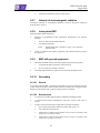
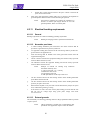
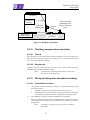
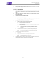
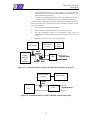
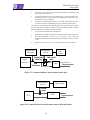
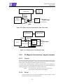
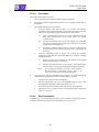
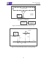
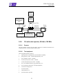
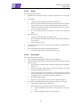
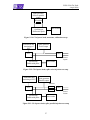
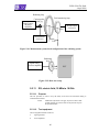
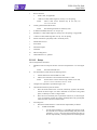
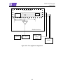
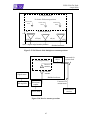
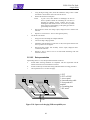
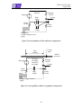
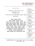
ECSS-E-20-07A Draft
4 April 2008
c.
4.
Scan the measurement receiver for each frequency in the same manner as a
normal data scan. Verify that the data-recording device indicates a level
within ±3 dB of the injected level.
5.
If readings are obtained which deviate by more than ±3 dB, locate the source
of the error and correct the deficiency prior to proceeding with the testing.
Test the EUT by determining the conducted emissions from the EUT input power
leads, hot line and return, and measure the conducted emission separately on each
power lead, as follows:
1.
Turn on the EUT and wait for its stabilization.
2.
Select a lead for testing and clamp the current probe into position.
3.
Scan the measurement receiver over the frequency range, using the
bandwidths and minimum measurement times specified in Table 5-2, clause
5.3.9.1.
4.
Repeat 5.5.2.4.c.2 and 5.5.2.4.c.3 for each power lead.
Measurement
receiver
Oscilloscope
Signal
generator
with
amplifier
Data
recorder
Coax “T” and
bifilar
transition
LISN
To power source
Current
Resistor probe
Figure 5-5: Conducted emission, 30 Hz to 100 kHz, measurement system check
Measurement
receiver
Data recorder
Current
probe
LISN
EUT
To power source
Figure 5-6: Conducted emission, 30 Hz to 100 kHz, measurement setup
39