1
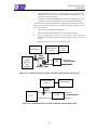
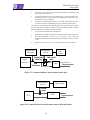
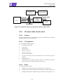
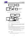
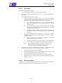
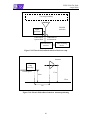
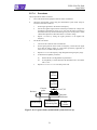
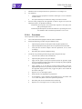
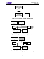
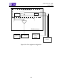
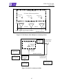
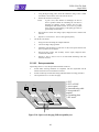
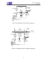
ECSS-E-20-07A Draft
4 April 2008
5.5.6.4
Procedures
The test procedures shall be as follows:
a.
Turn on the measurement equipment and wait until it is stabilized.
b.
Verify that the ambient requirements specified in 5.3.2.3 are met and take plots of
the ambient.
c.
Check the measurement system as follows:
1.
2.
Using the system check path of Figure 5-13, perform the following
evaluation of the overall measurement system from each antenna to the data
output device at the highest measurement frequency of the antenna:
(a)
Apply a calibrated signal level that is at least 6 dB below the limit
(limit minus antenna factor) to the coaxial cable at the antenna
connection point.
(b)
Scan the measurement receiver in the same manner as a normal data
scan, and verify that the data-recording device indicates a level within
±3 dB of the injected signal level.
(c)
If readings are obtained which deviate by more than ±3 dB, locate the
source of the error and correct the deficiency prior to proceeding with
the testing.
Using the measurement path of Figure 5-13, perform the following
evaluation for each antenna to demonstrate that there is electrical continuity
through the antenna:
(a)
Radiate a signal using an antenna or stub radiator at the highest
measurement frequency of each antenna.
(b)
Tune the measurement receiver to the frequency of the applied signal
and verify that a received signal of appropriate amplitude is present.
NOTE
d.
This evaluation is intended to provide a coarse indication
that the antenna is functioning properly. There is no
requirement to measure accurately the signal level.
Test the EUT by using the measurement path of Figure 5-13 and determining the
radiated emissions from the EUT and its associated cabling, as follows:
1.
Turn on the EUT and wait until it is stabilized.
2.
Scan the measurement receiver for each applicable frequency range, using
the bandwidths and minimum measurement times in 5.3.9.1
3.
Orient the antennas for both horizontally and vertically polarized fields.
4.
Repeat steps 5.5.6.4.d.2 and 5.5.6.4.d.3 for each antenna position determined
under 5.5.6.3.5.5.6.3c.
5.5.6.5
Data Presentation
In addition to 5.3.9.4, data presentation shall provide a statement verifying the electrical
continuity of the measurement antennas as determined in5.5.6.4.5.5.6.4c.2.
48