1
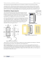
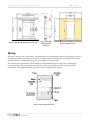
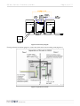
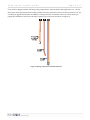
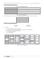
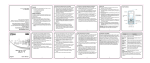
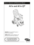
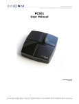
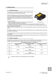
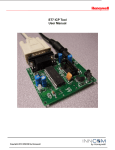
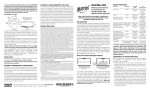
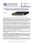
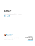
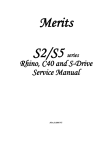
S5XX.Brit Product Guide
Page 1 of 7 S5XX Switch Series
Product Guide
Overview
The S5XX is a programmable switch can be configured to perform a range of functions required by a specific application. The S5XX offers up to five buttons that can be programmed for various guestroom commands, from lighting control to hallway displays. The S5XX can be ordered in a variety of formats and in both American and British gang styles—see the Ordering Specifications section for details. Note: the British S5XX differs only in its housing and dimensions. Wiring, technical specifications, and operation remain the same. Figure 1 S5XX American Gang Figure 2 S5XX British The S5XX accepts a Decora‐style cover. Order the press‐buttons for the S5XX separately; see the Press‐Button Product Guide for complete ordering information. The S5XX functions within INNCOM’s System‐5 communication protocol and interacts with other System‐5 devices. The S5XX is a multi‐tasking device that can interact with wired, infrared (IR), and radio frequency (RF) devices and act as a media gateway to overcome possible wiring installation challenges. The features of the S5XX include •
Offers multi‐control options, including control of lighting, drapes, requests for Do Not Disturb/Make Up Room, and other INNCOM devices; •
Offers five input/output ports for connection to other devices to suit functionality requirements; •
Can replace up to five individual mechanical switches in a British‐gang form; •
Can connect to the network server through an INNCOM interface device (B485); •
Can interface with INNCOM IR devices using a pinned header. Application
When the S5XX is configured with an IR eye and RF5 transceiver and connected to other INNCOM devices (such as INNCOM’s S217 Wireless Light Switch), it can transmit wired, IR, and RF messages in both directions. This allows door lock status, door/window status, thermostat data, and other information to flow freely among the devices. S5XX Series Product Guide
Page 2 of 7 The S5XX input ports support IR and RF transceiver attachment, and the device interconnection provides a comprehensive flow of information that enhances guestroom control and guest satisfaction. Because the S5XX is low‐voltage and can transmit wirelessly (with an external IR transmitter), it offers an expansive list of options to designers and architects for providing lighting control and other guest control functions at a reasonable cost. The S5XX also offers extensive switching capability without covering a large wall section with conventional switches. Installation Requirements
The S5XX includes both the functional press‐buttons and the switch. The press‐buttons are ordered separately from the switch; therefore, the first installation requirement is to snap the press‐buttons into the switch (Figure 3). If the press‐buttons display words or icons, care must be taken to ensure that the buttons are snapped into the switch in the correct position. The S5XX can then be mounted in an American single‐gang (ASG) electrical box, a single‐gang mud ring, or a single‐gang low‐voltage caddy. The plastic wall caddy shown in Figure 1 is the best option for mounting the S5XX in drywall. It is the most cost‐effective solution, and it provides a low‐profile mounting depth and ease of installation. (British gang mounting and dimensions are shown in Figures 6 and 7.) Figure 3 S5XX Press Button
Figure 5 American Gang Decora Cover Figure 4 S5XX ASG with Dimensions After the S5XX is screwed into the electrical box, the Decora cover can be snapped into place (Figure 5). This hides the mounting brackets and gives a neat appearance to the finished product. British Gang Mounting. The S5XX can also be mounted in a British style single‐gang (BSG) electrical box by means of a mounting frame that fits the British‐style box (Figure 6). In this application, the S5XX mounting screws pass through the mounting frame, eliminating the clamps shown in Figures 4 and 5. Figure 7 shows a side view of the mounting frame, giving the unit’s depth measure. Figure 8 shows the S5XX BSG front cover, which snaps over the .S5XX just as with the ASG version. S5XX Series Product Guide
Page 3 of 7 Figure 6 S5XX BSG Mounting Frame Front view
Figure 7 S5XX BSG Mounting Frame Side View Figure 8 S5XX BSG Cover
Wiring
The S5XX is strictly a low‐voltage device, and termination is by pinned headers (Figure 9). The S5XX is powered through INNCOM’s S5‐bus and, as shown in the connectivity diagram (Figure 10), can be integrated with other INNCOM devices. It is designed to be part of a comprehensive control system. The S5XX has two 5‐pin headers: one for linking to an INNCOM IR transceiver, and one for connecting to network hardware. Two 3‐pin headers connect to the S5‐bus. A 7‐pin header provides other optional I/O functionality, and an eight‐pin header provides access for programming the device. Figure 9 S5XX Input/Output Ports
S5XX Series Product Guide
Page 4 of 7 Figure 10 Connectivity Diagram
If using an American double‐gang box, connect the S5XX GND to the incoming GND (Figure 11). Figure 11 Separation of Circuits
S5XX Series Product Guide
Page 5 of 7 Every S5XX is shipped with the following wiring components to meet the needs of the application: a 6” (15 cm) three‐pin‐to‐three‐pin harness (Part Number 62‐2033) for wiring the S5XX to devices in close proximity, a 10” (25 cm) three‐pin pigtail (Part Number 62‐1465B) for wiring to devices at a distance, and a 12” (30 cm) seven‐pin pigtail (Part Number 62‐1516‐A) for the S5XX expansion port. The wires are shown in Figure 12. Figure 12 Wiring Components Included with S5XX
S5XX Series Product Guide
Page 6 of 7 Technical Specifications
Table 1. Technical Specifications Input Power 12VDC, 30 mA (see Table 2 for specific current consumption values) Operating Environment 40 to 150 ˚F (5 to 65 ˚C) Mounting 16‐gauge wall mount bracket (provided) Dimensions See Figure 1. Approvals FCC Part 15 Table 2. Current Consumption Current Consumption = 15 mA + N (3mA) + External Load where N is the number of LEDs in the product. S55—18 mA + External Load S552—21 mA + External Load S553—24 mA + External Load S554—27 mA + External Load S555—30 mA + External Load Ordering Specifications
Part Name Part Number S5xs.l.c.m.r 01‐9605.x.s.l.c.m.r X Controller •
•
•
•
S 1 = passive (requires a controller to operate) 2 = passive interconnect for P264 legacy interface (use with switch configuration 2) 4 = reserved (to avoid S541 naming collision) 5 = active (S5Bus compatible) Switch configurations Figure 13 Switch Configurations
S5XX Series Product Guide
l LED configurations •
•
•
•
•
c Page 7 of 7 x = all blank keys (no LED window) r = all red LEDs g = all green LEDs b = all blue LEDs s = special (INNCOM to provide special instructions) Color •
•
•
wh = white ea = eagle almond bl = black m Model/Switch •
•
•
•
•
r E = Empty (no switches inserted at factory) N = Neutral (not silk‐screened) DMT = Do Not Disturb, MUR (text) DMG = Do Not Disturb, MUR (graphic) MS = Master Switch Revision Code: Under most circumstances, customers do not need to concern themselves with the revision of a product. However, if a specific revision is required for the application, the revision number should be inserted in place of the letter “r.” If no revision is indicated, the latest revision will be provided. Order example: S522.g.wh.DMG – A passive two‐button device that can serve in a System‐6 legacy, containing all green LEDʹs, manufactured in white, and containing Do Not Disturb and MUR graphics. No revision is indicated, so the latest revision will be provided. Note: The press‐buttons (Part Number 53‐9960) used for the S5XX are common to several INNCOM devices and are ordered separately. The press‐buttons are fully customizable, and there are many options with regard to press‐button LEDs and text. Commissioning Requirements
The S5XX supports being assigned a device address and device channel, and these commands can be executed from a linked e4 Smart Digital Thermostat, a sneezer tool, or the central server. For detailed information on assigning address and channel, see the S5XX User Manual. Document Revision History
Table 3. Document Revision History REVISION V1.0 V1.1 V1.2 V1.3 DATE ISSUED 02‐Jan‐2007 13‐Apr‐2007 V1.4 07‐Oct‐2011 REASON FOR CHANGE First issue Ordering information was updated. Information about British style mounting was added. GND wire was added to the figures; information about grounding was added to the installation instructions;. Drawings, BSG information, format updated