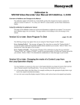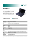
1
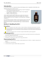
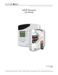
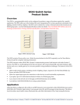
Global Leader in Integrated Room Automation Systems Copyright © 2012 INNCOM ES-1 (External Storage) User Manual This document contains information that is the proprietary and confidential property of INNCOM international, inc. By acceptance hereof, each recipient agrees to use the information contained herein only for the purpose anticipated by INNCOM and not to disclose to others, copy, or reproduce any part hereof without the written consent of INNCOM. The recipient agrees to return this document to INNCOM immediately upon request. ES-1 User Manual Page 2 of 6 Table of Contents INTRODUCTION .....................................................................................................................................................................3 SECTION 1 HANDLING THE ES-1.......................................................................................................................................3 PRECAUTIONS ............................................................................................................................................................................3 CONNECTING THE ES-1 .............................................................................................................................................................3 DISCONNECTING THE ES-1........................................................................................................................................................3 SECTION 2 PROGRAM TRANSFER ....................................................................................................................................4 STORE A PROGRAM INTO ES-1 ..................................................................................................................................................4 UPGRADE THERMOSTAT PROGRAM ...........................................................................................................................................5 SECTION 3 CONFIGURATION TRANSFER ......................................................................................................................5 STORE CONFIGURATION INTO ES-1...........................................................................................................................................5 UPGRADE THERMOSTAT CONFIGURATION ................................................................................................................................6 SECTION 4 SPECIFICATIONS .............................................................................................................................................6 SECTION 5 DOCUMENT INFORMATION AND REVISION HISTORY........................................................................6 ES-1 User Manual Page 3 of 6 Introduction 0B ES‐1 (External Storage 1) is a companion memory module (Figure 1) that is compatible with INNCOM’s e528‐ 2004 digital thermostat. Its primary uses are Storing thermostat program (software) for allowing a simple one‐step (plug‐in) software upgrade of standalone thermostats. Storing thermostat configuration data for a simple one‐step configuration upgrade of standalone thermostats. Tracking of commissioning progress All ES‐1 Memory Module features and benefits described in this document require an e528 thermostat hardware from the year 2004 or later, running a software package V2.82 or later. In addition, any e527 thermostat is compatible with the ES‐1. It is assumed that the reader is familiar with the engineering options of the e528 thermostat, in particular how to enter, navigate, and execute functions in the thermostat service mode. For information on this topic, consult the e528 User Manual. Section 1 Handling the ES-1 Figure 1 ES‐1 Memory Module 1B Precautions 6B Do not touch the pins on the connector of the ES‐1. Electric discharge can damage the electronic devices in the unit. Do not touch the pins or come close to the pins of the ES‐1 receptacle on the e528 thermostat. Electric discharge can damage the electronic devices in the thermostat. If possible, discharge your body of static electricity before removing the receptacle cap. For thermostat protection, always cover the ES‐1 receptacle with the rubber cap after using the ES‐1. Connecting the ES-1 7B 1. To avoid exposing components to static electricity, take precautions to ground the static electricity by wearing an ESD wrist strap or working on an anti‐static mat. 2. Remove the rubber cap on the bottom of the e528 thermostat. 3. Insert the ES‐1 into the thermostat. The ES‐1 label is facing towards the user. Disconnecting the ES-1 8B 4. Do not disconnect until the operation in progress is finished. Mid‐term aborts can lead to a corruption of the operation in progress. 5. Unplug the ES‐1 from the thermostat. 6. Cover the thermostat receptacle with the rubber cap for protection. ES-1 User Manual Page 4 of 6 Figure 2 Connecting the ES‐1 to the Thermostat Section 2 2B Program Transfer This section explains how the software (program) of a thermostat can be transferred to another thermostat, running a different project revision, project‐build, or program package; in short, how to clone the software of a reference thermostat to other thermostats. Store a Program into ES-1 9B 1. 2. Verify the reference thermostat is the correct one to copy from. Verification tests might include but are not limited to Check software package version Check project version and revision Perform functional tests to assure the fitness of the software for the intended application Get the ES‐1 that will hold the program. Verify that it holds no potentially valuable information that might inadvertently be overwritten. 3. Remove the rubber cap on the thermostat receptacle. 4. Enter the service mode of the thermostat. 5. Execute the service parameter 2:20 “Store Program into ES‐1.” The thermostat will now blink “ES1.” 6. While the thermostat blinks “ES1,” insert the ES‐1 module as described in “Connecting the ES‐1.” The thermostat will instantly recognize a formatted ES‐1 module and begin copying. In the case of an unformatted ES‐1, the thermostat will continue to blink the “ES1” message but will begin copying after about 15 seconds. 7. The thermostat copies the program into the ES‐1. To display the progress, the thermostat displays a counter running from 0 to 223. 8. The operation succeeded if the display of the thermostat returns back to the service mode (displaying Value 20). 9. Remove the ES‐1 from the thermostat. 10. Replace the rubber cap on the ES‐1 receptacle in the thermostat. 11. Label the ES‐1. Include the software version, property name, and date. ES-1 User Manual Page 5 of 6 Unplugging the ES‐1 during the copy operation will abort the copy process; however, the incomplete process will not corrupt the thermostat or affect it in any manner. Upgrade Thermostat Program 1. Verify that the target thermostat is really required to have the software upgraded. 2. Remove the rubber cap of the thermostat receptacle. 3. Insert the ES‐1 into the receptacle. 4. The unit copies the software into a temporary storage area. During this time, the LCD shows a counter incrementing from 0 to 223. Note: If the thermostat display shows the key type but nothing more, the upgrade is not taking place. The most likely cause of this is that the program in the thermostat is the same as that in the ES‐1. This can be verified by checking the code on the thermostat. 5. When software copying is finished, the LCD shows a counter decrementing from 100 to 0. Remove the ES‐1 at any time during this countdown phase. 6. Replace the rubber cap on the ES‐1 receptacle in the thermostat. Upgrading thermostat software is a two‐phase programming cycle. In phase one, the LCD backlight blinks slowly. During this phase, the memory of the thermostat is erased. In the second phase, the display blinks faster. This is when the actual software is copied into the thermostat. Please note that during these two phases, the thermostat is not in a stable condition – if you remove power from the thermostat, you will need an ICP tool to load software into the thermostat. Section 3 Configuration Transfer 3B The ES‐1 can also be used to transfer the non‐volatile configuration parameters from one thermostat to another thermostat. The user has the option of transferring either the HVAC/Room Control related parameters, or the P5 Communication related parameters, or both. In no case would essential specific data, such as thermostat calibration, Room ID, etc., be copied from one unit to another. Store Configuration into ES-1 10B 1. Verify the reference thermostat is the correct one to copy from. Verification tests might include but are not limited to 2. Get the ES‐1 that will hold the program. Verify that it holds no potentially valuable information that might inadvertently be overwritten. 3. Remove the rubber cap on the thermostat receptacle. 4. Enter the service mode of the thermostat. 5. Execute the service parameter: 6. “Store HVAC Parameters.” “Store P5 Communication Parameters.” “Store HVAC and P5 Communication Parameters.” The thermostat will now blink “ES1.” While the thermostat blinks “ES1,” insert the ES‐1 module as described in “Connecting the ES‐1.” The thermostat will instantly recognize a formatted ES‐1 module and begin copying. In case of an unformatted ES‐1, the thermostat will continue to blink the “ES1” message but will begin copying after about 15 seconds. The thermostat copies the selected configuration parameters into the ES‐1. To show progress, the thermostat displays a counter running from 0 to 255. The operation succeeded if the display of the thermostat returns back to the service mode (displaying Value 21/22/23). Remove the ES‐1 from the thermostat. ES-1 User Manual Page 6 of 6 7. Replace the rubber cap on the ES‐1 receptacle in the thermostat. 8. Label the ES‐1. Include the room type, software version, property name, and date. Unplugging the ES‐1 during the copy operation will lead to an incomplete ES‐1 content; however, the incomplete process will not corrupt the thermostat or affect it in any manner. Upgrade Thermostat Configuration 1B 1. Verify that the target thermostat is really required to have the configuration upgrade. 2. Remove the rubber cap of the thermostat receptacle. 3. Insert the ES‐1 into the receptacle. 4. The unit copies the configuration into the target thermostat. To show progress, the thermostat displays a counter running from 0..255. 5. The thermostat resets. 6. During thermostat startup, remove the ES‐1. 7. Replace the rubber cap on the ES‐1 receptacle in the thermostat. DO NOT remove the ES‐1 from the thermostat during configuration upload. This could result in corrupted settings, and a manual parameter reboot might become necessary. Section 4 Specifications 4B Table 1. Technical Specifications Power requirement Dimensions 12VDC, 10mA regulated Inches: 1.75 H x 0.75 W x 0.125 D Centimeters: 4.45 H x 1.9 W x 0.312 D Storage ‐4 to 176 F (‐20 to 80 C), non condensing Operating 50 to 122 F (10 to 50 C), non condensing Memory 64 Kbytes Section 5 Document Information and Revision History 5B This user manual is part of INNCOM’s controlled documentation and is protected by copyright. To request changes to this document, contact INNCOM international, inc. at (860) 739‐4468. Table 2. Revision History DATE REVISION REASON 30‐Mar‐2004 First Issue 12‐Sep‐2006 V1.1 Reformatting, general editing, general review for updating purpose 16‐Jan‐2012 V1.2 Update to latest document template