1
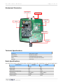
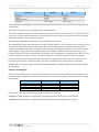
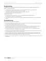
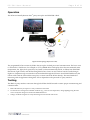
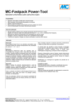
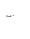
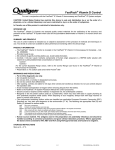
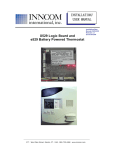
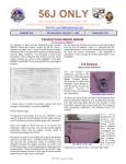
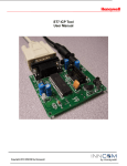
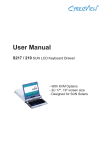
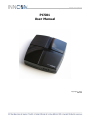
PC501 User Manual
Global Leader in Integrated Room Automation Systems
PC501
User Manual
Copyright © 2010
INNCOM
PC501 User Manual
Page 2 of 8
Overview
The PC501 protocol converter bridges INNCOM Integrated Room Automation System (IRAS) with 3rd-party
interfaces to provide onscreen guestroom environmental control through TV, smartphone, or other digital
devices. Using a USB cable both for power and for data transfer to a set-top box, the platform-independent PC501
can translate settings from the 3rd-party interface to standard P5 commands for heating, lighting, or other room
equipment. In turn, the PC501 can forward information from INNCOM-controlled environmental systems back
through the 3rd-party interface for display and adjustment onscreen. The PC501 features S5bus, IR, and RF
communications.
Technical Information
Major components (see Figure 1) of the compact (X inches by Y inches) PC501 include
•
S217IR logic board: provides infrared (IR5) and S5bus capabilities
•
CC2430 RF: provides RF capabilities
•
CC2430 radio programming header
•
Mini-USB connector and cable: connection to set-top box
•
Two S5bus headers
•
3 LEDs: Red indicates power, middle violet indicates transmission (Rx/Tx), outer violet indicates programming
Both the S217IR and the CC2430 must be loaded with application software that supports the FastPack Serial
Protocol (see Programming). This software allows FastPack Control commands from the 3rd-party interface to be
translated into P5 commands sent out by IR5, S5bus, or RF to the IRAS and for IRAS updates to flow back
through the USB/Serial port as FastPack Controls.
Note: The set-top box will differ according to the 3rd party collaborator (e.g., Enseo, Exceptional Innovation).
Generally, it will be a video on demand (VoD) device with a dedicated USB port for communication with and power
for the PC501. The vendor must develop the FastPack Serial Protocol for interaction with INNCOM devices as well
as supporting FTDI Serial drivers for the USB connection.
PC-501 User Manual
Page 3 of 8
Mechanical Illustration
S5bus header
S5bus header
CC2430 0dB
radio
S217IR
Indicator LEDs
MiniUSB
Technical Specifications
Dimensions
95mm x 95mm x 25mm
USB connector
Mini USB 5-pin header
Communications
Infrared (IR5), S5bus, RF, 802.15.4
Power
See current consumption chart in table x.
Approvals
FCC Part 15
Radio Specifications
The PC501 houses either a 0dB (P/N 02-9994) or 20dB (P/N 02-9894) radio, depending on the required application.
Performance
02-9994
02-9894
RF Data Rate
Antenna Type
250kbps
SMT
SMT
SMT
Indoor Range
70ft
100ft
Outdoor/ RF line-of-sight range
Transmit Power
540ft
1mW (+0dBm)
1000ft+
10mW (+18dBm)
Receive Sensitivity
-94.6dBm
-94.6dBm
Frequency Band
2.4Ghz
2.4Ghz
PC-501 User Manual
Page 4 of 8
Performance
02-9994
02-9894
Encryption
AES-128
AES-128
Protocol
802.15.4
802.15.4
Frequency Channels
Dimensions
11–26
28mm x 38mm
11–26
28mm x 38mm
All Final Products containing the INNCOM TXR 02-9894 or TXR 02-9994 must contain the following statements
on their label:
This device contains FCC ID: GTC029894TXR or GTC029994TXR.
This device complies with part 15 of the FCC Rules. Operation is subject to the following two conditions: (1) This
device may not cause harmful interference, and (2) this device must accept any interference received, including
interference that may cause undesired operation.
The followings statements are required in the final product user manuals:
This equipment has been tested and found to comply with the limits for a Class A digital device, pursuant to Part
15 of the FCC Rules. These limits are designed to provide reasonable protection against harmful interference
when the equipment is operated in a commercial environment. This equipment generates, uses, and can radiate
radio frequency energy and, if not installed and used in accordance with the instruction manual, may cause
harmful interference to radio communications. Operation of this equipment in a residential area is likely to cause
harmful interference, in which case the user will be required to correct the interference at his own expense.
All Final Products containing the INNCOM TXR 02-9894 or TXR 02-9994 should be kept at a safe distance of at
least 20cm from all persons. The final product cannot be co-located with any other antenna or transmitter.
Modifications not expressly approved by INNCOM International Inc. could void the user’s authority to operate
the equipment.
Power Consumption
The PC501 has multiple types of transmission mediums such as a 1mW radio, 20mW radio, IR transmitter, and
hardwired S5bus communications. Peak values are based on current consumption measured while transmitting
each medium.
Parameter
PC501 logic board
S217 logic board
0dB (02-9994)
20dB (02-9894)
Nominal
20mA
20mA
10mA
10mA
Peak
20mA
50mA
30mA
70mA
Peak current values are measured during IR, RF, or S5bus transmissions.
Example 1: 01-5001.PC.R3.S0.P configuration, the nominal current is 30mA, peak current is 50mA.
Example 2: 01-5001.PC.R1.S1.P configuration, the nominal current is 50mA, peak current is 110mA.
PC-501 User Manual
Page 5 of 8
Programming
As indicated above, both the S217IR and the CC2430 must be programmed to support the FastPack Serial
Protocol. To program the S217R
1.
Use the INNCOM ST7 Flash Bash programmer as usual. (See INNCOM ST7 ICP User's Manual found in
T:\FTP\Eng_Data\Products\PC\INNCOM ST7 ICP\Documents)
2.
Load the latest available software package located in the T:\Library\INNCOM
Products\Devices\S217_CBL\S217_FPS_IR5 directory.
To program the CC2430
1.
Use the ELAB UPP-1 JTag programmer as usual. (See E-LAB Zigbee ICP User's Manual, found in
T:\FTP\Eng_Data\Products\PC\E-LAB Zigbee ICP)
3.
Load the latest available software package located in the T:\Library\INNCOM Products\Devices\CC2430 Radio\FPS
directory.
Commissioning
The PC501 must be bound to the room IRAS:
1.
Enter the Service Mode on the e4 thermostat (press and hold the °F/°C button; press and release the OFF/AUTO button;
press and release the DISPLAY button; release the °F/°C button)
2.
Set parameter 14 on the thermostat to the specific I/O map if necessary
3.
Set parameter 15 on the thermostat to the reserved P5 device address (234). Leave the thermostat parked in PAR 15
displaying the device address (VAL: 234). This puts the thermostat into bind ready mode for the PC501.
4.
Power up the PC501 (either by connecting it to a power source through the 3-pin S5 bus or by plugging in the USB
connector to the 3rd-party box or the USB connector on a laptop)
5.
Upon power up, the PC501 sends a “bind offer” message that it is prepared for binding. The thermostat will confirm that
it received the bind offer from the PC501 by scrolling its display
6.
The PC501 confirms receipt of the device configuration data from the thermostat by sending a buzzer VFI back to the
thermostat. Typically, the buzzer VFI will be sent approximately 10 seconds after the devices have been bound. This
confirms a link has been established between the PC501 and the correct thermostat
7.
The Enseo box only recognizes the PC501 on startup. Reboot the Enseo box to complete the networking of the devices (see
Testing below)
PC-501 User Manual
Page 6 of 8
Operation
The PC501 sits literally between the 3rd-party set-top box and INNCOM’s IRAS.
Figure 1 PC-501 topology (objects not to scale)
The programmed PC501 connects by USB to the set-top box for both power and communication. The box in turn
is connected to a VoD device, for example, to a TV by HDMI cable. The display shows the environmental status
(temperature, fan, lights, door open/close, etc.) based on data transmitted (by IR, RF, or S5bus) from INNCOM
thermostats, light controls, and the like through the PC501. Guests can use a remote control to make changes
(lights on, temperature up) onscreen that can be translated through the PC501 to control INNCOM devices (the
remote works with the VoD and the set-top box; it cannot control the PC501 directly). The actual method of
interacting with the application through the VoD is dependent on the particular 3rd-party interface.
Testing
The IRAS-3rd-party interface connection through the PC501 should be tested to ensure proper commissioning and
communication.
1.
Reboot the 3rd-Party set-top box to verify connection to the PC501
2.
Use the remote to change environmental conditions (e.g., raise or lower temperature, change lighting) using the VoD
screen. Verify that changes are made in the INNCOM devices.
3.
Change conditions using the e4. Verify that changes are noted in the VoD screen.