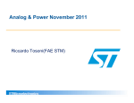
1
UM1483 User manual Low power motor control board STEVAL-IHM036V1 featuring SLLIMM™ STGIPN3H60 and MCU STM32F100C6T6B 1 Introduction This document describes the low power motor control board STEVAL-IHM036V1 featuring the SLLIMM™ (small low-loss intelligent molded module) STGIPN3H60 and MCU STM32F100C6T6B. The demonstration board is an AC/DC inverter that generates a 3-phase waveform for driving 3-phase permanent magnet synchronous motors (PMSM) with field-oriented control (FOC) up to maximal 100 W without sensors. The used controller belongs to the STMicroelectronics™ ARM® Cortex™-M3 core-based medium density STM32™ MCU family. The main device presented in this user manual is a universal, fully evaluated and populated design consisting of a 3-phase inverter bridge based on the 600 V IGBT power module in NDIP-26L package. The IGBT power module integrated all power IGBT switches with freewheeling diodes together with the high voltage gate drivers. Thanks to this integrated module, the system has been specifically designed to achieve power inverter in a reliable and compact design. Such integration saves PCB space occupation and assembly costs together with high reliability due to the design simplicity. The board is designed to be compatible with single-phase mains for the European range of supply voltage 230 VAC (+/- 15%), or corresponding DC supply voltage. The board includes a power supply stage with VIPer™16 in buck configuration to generate +15 V supply voltage required by the application. This document is associated with the release of the STEVAL-IHM036V1 demonstration board (see Figure 1). Figure 1. November 2011 STEVAL-IHM036V1 Doc ID 022398 Rev 1 1/35 www.st.com Contents UM1483 Contents 1 Introduction . . . . . . . . . . . . . . . . . . . . . . . . . . . . . . . . . . . . . . . . . . . . . . . . 1 2 System introduction . . . . . . . . . . . . . . . . . . . . . . . . . . . . . . . . . . . . . . . . . 6 3 4 2/35 2.1 Main characteristics . . . . . . . . . . . . . . . . . . . . . . . . . . . . . . . . . . . . . . . . . . 6 2.2 Target application . . . . . . . . . . . . . . . . . . . . . . . . . . . . . . . . . . . . . . . . . . . . 6 2.3 Safety and operating instructions . . . . . . . . . . . . . . . . . . . . . . . . . . . . . . . . 7 2.3.1 General terms . . . . . . . . . . . . . . . . . . . . . . . . . . . . . . . . . . . . . . . . . . . . . 7 2.3.2 Demonstration board intended use . . . . . . . . . . . . . . . . . . . . . . . . . . . . . 7 2.3.3 Demonstration board installation . . . . . . . . . . . . . . . . . . . . . . . . . . . . . . . 7 2.3.4 Electrical connections . . . . . . . . . . . . . . . . . . . . . . . . . . . . . . . . . . . . . . . 8 Board description . . . . . . . . . . . . . . . . . . . . . . . . . . . . . . . . . . . . . . . . . . . 9 3.1 System architecture . . . . . . . . . . . . . . . . . . . . . . . . . . . . . . . . . . . . . . . . . . 9 3.2 The board schematic . . . . . . . . . . . . . . . . . . . . . . . . . . . . . . . . . . . . . . . . 10 3.3 Board architecture description . . . . . . . . . . . . . . . . . . . . . . . . . . . . . . . . . 13 3.3.1 Power supply . . . . . . . . . . . . . . . . . . . . . . . . . . . . . . . . . . . . . . . . . . . . . 13 3.3.2 Input part of the converter . . . . . . . . . . . . . . . . . . . . . . . . . . . . . . . . . . . 14 3.3.3 Control block with value line STM32 MCU . . . . . . . . . . . . . . . . . . . . . . . 14 3.3.4 Power block based on IGBT module . . . . . . . . . . . . . . . . . . . . . . . . . . . 16 3.3.5 Overcurrent protection . . . . . . . . . . . . . . . . . . . . . . . . . . . . . . . . . . . . . . 16 3.3.6 Single-shunt current sensing amplifying network . . . . . . . . . . . . . . . . . 17 3.3.7 Temperature feedback . . . . . . . . . . . . . . . . . . . . . . . . . . . . . . . . . . . . . . 19 Testing of the demonstration board . . . . . . . . . . . . . . . . . . . . . . . . . . . 20 4.1 Hardware test results of EMC compliance with EN rules EMC IEC 61000-4-4 burst immunity . . . . . . . . . . . . . . . . . . . . . . . . . . . . . 21 4.2 Hardware test results of EMC compliance with EN rules EMC IEC 61000-4-5 surge tests . . . . . . . . . . . . . . . . . . . . . . . . . . . . . . . 21 4.3 Radio disturbance characteristic according to EN55014 (CISPR14-1) . . . . . . . . . . . . . . . . . . . . . . . . . . . . . . . . . . . . . . . . . . . . . . . 22 Doc ID 022398 Rev 1 UM1483 5 6 Contents Using STEVAL-IHM036V1 with the STM32 PMSM FOC SDK v3.0 Motor Control Firmware Library . . . . . . . . . . . . . . . . . . . . . . . . . . . . . . 23 5.1 Environmental considerations . . . . . . . . . . . . . . . . . . . . . . . . . . . . . . . . . 23 5.2 Hardware requirements . . . . . . . . . . . . . . . . . . . . . . . . . . . . . . . . . . . . . . 24 5.3 Software requirements . . . . . . . . . . . . . . . . . . . . . . . . . . . . . . . . . . . . . . . 24 5.4 STM32 motor control firmware library v3.0 customization . . . . . . . . . . . . 24 Description of STEVAL-IHM036V1 connections . . . . . . . . . . . . . . . . . . 27 Connector placement . . . . . . . . . . . . . . . . . . . . . . . . . . . . . . . . . . . . . . . . . . . . . . 27 7 Bill of material . . . . . . . . . . . . . . . . . . . . . . . . . . . . . . . . . . . . . . . . . . . . . 28 8 PCB layout . . . . . . . . . . . . . . . . . . . . . . . . . . . . . . . . . . . . . . . . . . . . . . . . 31 9 Ordering information . . . . . . . . . . . . . . . . . . . . . . . . . . . . . . . . . . . . . . . 33 10 Conclusion . . . . . . . . . . . . . . . . . . . . . . . . . . . . . . . . . . . . . . . . . . . . . . . . 33 11 References . . . . . . . . . . . . . . . . . . . . . . . . . . . . . . . . . . . . . . . . . . . . . . . . 34 12 Revision history . . . . . . . . . . . . . . . . . . . . . . . . . . . . . . . . . . . . . . . . . . . 34 Doc ID 022398 Rev 1 3/35 List of tables UM1483 List of tables Table 1. Table 2. Table 3. Table 4. Table 5. Table 6. Table 7. 4/35 Jumper settings single/dual supply mode . . . . . . . . . . . . . . . . . . . . . . . . . . . . . . . . . . I/O assignment . . . . . . . . . . . . . . . . . . . . . . . . . . . . . . . . . . . . . . . . . . . . . . . . . . . . . . STEVAL-IHM036V1 motor control workbench parameters for power part . . . . . . . . . STEVAL-IHM036V1 motor control workbench parameters for control and drive part Test pins description . . . . . . . . . . . . . . . . . . . . . . . . . . . . . . . . . . . . . . . . . . . . . . . . . . Bill of material . . . . . . . . . . . . . . . . . . . . . . . . . . . . . . . . . . . . . . . . . . . . . . . . . . . . . . . Document revision history . . . . . . . . . . . . . . . . . . . . . . . . . . . . . . . . . . . . . . . . . . . . . Doc ID 022398 Rev 1 . . . . 14 . . . . 15 . . . . 25 . . . . 26 . . . . 27 . . . . 28 . . . . 34 UM1483 List of figures List of figures Figure 1. Figure 2. Figure 3. Figure 4. Figure 5. Figure 6. Figure 7. Figure 8. Figure 9. Figure 10. Figure 11. Figure 12. Figure 13. STEVAL-IHM036V1 . . . . . . . . . . . . . . . . . . . . . . . . . . . . . . . . . . . . . . . . . . . . . . . . . . Motor control system architecture. . . . . . . . . . . . . . . . . . . . . . . . . . . . . . . . . . . . . . . . STEVAL-IHM036V1 schematic - part 1 . . . . . . . . . . . . . . . . . . . . . . . . . . . . . . . . . . . STEVAL-IHM036V1 schematic - part 2 . . . . . . . . . . . . . . . . . . . . . . . . . . . . . . . . . . . STEVAL-IHM036V1 schematic - part 3 . . . . . . . . . . . . . . . . . . . . . . . . . . . . . . . . . . . Power supply block diagram . . . . . . . . . . . . . . . . . . . . . . . . . . . . . . . . . . . . . . . . . . . . Overcurrent protection based on STGIPN3H60 . . . . . . . . . . . . . . . . . . . . . . . . . . . . . Single-shunt FOC network . . . . . . . . . . . . . . . . . . . . . . . . . . . . . . . . . . . . . . . . . . . . . Efficiency of the STEVAL-IHM036V1, temperature of the STGIPN3H60 . . . . . . . . . . EMC conducted emissions, detector average . . . . . . . . . . . . . . . . . . . . . . . . . . . . . . STEVAL-IHM036V1 connector placement . . . . . . . . . . . . . . . . . . . . . . . . . . . . . . . . . Component placement - top side . . . . . . . . . . . . . . . . . . . . . . . . . . . . . . . . . . . . . . . . Component placement - bottom side . . . . . . . . . . . . . . . . . . . . . . . . . . . . . . . . . . . . . Doc ID 022398 Rev 1 .....1 .....9 . . . . 10 . . . . 11 . . . . 12 . . . . 13 . . . . 17 . . . . 19 . . . . 20 . . . . 22 . . . . 27 . . . . 31 . . . . 32 5/35 System introduction UM1483 2 System introduction 2.1 Main characteristics The information listed below shows the converter specification data and the main parameters set for the STEVAL-IHM036V1 demonstration board. 2.2 6/35 ● Minimum input voltage 275 VDC or 195 VAC ● Maximum input voltage 375 VDC or 265 VAC ● Maximum output power for applied motor up to 100 W ● Input inrush limitation based on NTC resistor ● +15 V auxiliary power supply based on a buck converter with VIPer16 ● Using IGBT SLLIMM™ STGIPN3H60 in NDIP-26L molded package ● Fully populated board conception with test points ● Overcurrent hardware protection ● Overtemperature protection based on NTC resistor ● Based on STMicroelectronic's ARM® Cortex™-M3 core-based STM32F100C6T6B microcontroller ● Possibility to modify the board with RS-485 bus ● Field-oriented control (FOC) firmware customized with “STM32 PMSM FOC SDK v3.0 Motor Control Firmware Library” (see www.st.com/internet/com/ SOFTWARE_RESOURCES/SW_COMPONENT/FIRMWARE/stm32_pmsm_foc_moto rcontrol_fwlib.zip) ● Compliance with EN55014 (CISPR 14), IEC 61000-4-5 and IEC61000-4-4 ● PCB type and size: – Material of PCB - FR-4 – Double-sided layout – Copper thickness: ~60 μm – Total dimensions of demonstration board: circular shape, diameter 115 mm Target application ● Household water heating pumps ● Dishwasher pumps ● Refrigerator compressors ● High-end fans Doc ID 022398 Rev 1 UM1483 System introduction 2.3 Safety and operating instructions 2.3.1 General terms Warning: During assembly, testing, and normal operation, the demonstration board poses several inherent hazards, including bare wires, moving or rotating parts and hot surfaces. There is danger of serious personal injury and damage to property if the kit or components are improperly used or installed incorrectly. The kit is not electrically isolated from the AC/DC input. The demonstration board is directly linked to the mains voltage. No insulation is ensured between the accessible parts and the high voltage. All measuring equipment must be isolated from the mains before powering the board. When using an oscilloscope with the demo, it must be isolated from the AC line. This prevents shock from occurring as a result of touching any single point in the circuit, but does NOT prevent shock when touching two or more points in the circuit. Do not touch the demonstration board after disconnection from the voltage supply; several parts and power terminals, which contain energized capacitors, must be allowed to discharge. All operations involving transportation, installation and use, as well as maintenance, are to be carried out by skilled technical personnel (national accident prevention rules must be observed). For the purpose of these basic safety instructions, “skilled technical personnel” are considered as suitably qualified people who are familiar with the installation, use, and maintenance of power electronic systems. 2.3.2 Demonstration board intended use The STEVAL-IHM036V1 demonstration board is designed for demonstration purposes only and must not be used in final applications. The technical data, as well as information concerning the power supply conditions, must only be taken from the relevant documentation and must be strictly observed. 2.3.3 Demonstration board installation The installation and cooling of the demonstration board must be in accordance with the specifications and the targeted application. ● The motor drive converters are protected against excessive strain. In particular, no components are to be bent or isolating distances altered during the course of transportation or handling. ● No contact must be made with other electronic components and contacts. ● The boards contain electrostatically sensitive components that are prone to damage through improper use. Electrical components must not be mechanically damaged or destroyed. Doc ID 022398 Rev 1 7/35 System introduction 2.3.4 UM1483 Electrical connections Applicable national accident prevention rules must be followed when working on the main power supply. The electrical installation must be carried out in accordance with the appropriate requirements. A system architecture which supplies power to the demonstration board must be equipped with additional control and protective devices in accordance with the applicable safety requirements (e. g. compliance with technical equipment and accident prevention rules). 8/35 Doc ID 022398 Rev 1 UM1483 Board description 3 Board description 3.1 System architecture A generic motor control system can be basically schematized as the arrangement of four main blocks (see Figure 2). ● Control block - its main task is to accept user commands and motor drive configuration parameters. It provides all digital signals to implement the proper motor driving strategy. The STM32F100C6T6B MCU belongs to the value line medium and low density STM32 MCU family and was selected as the key component of the control block. ● Power block - it is based on 3-phase inverter topology. The heart of the power block is the STGIPN3H60 small low-loss intelligent molded module which contains all the necessary active components. Please refer to the STGIP3H60 datasheet for more information. ● Motor - The STEVAL-IHM036V1 demonstration board is able to properly drive any PMSM up to 100 W of nominal power, but the FOC itself is mostly conceived for sinusoidal shaped back-EMF. ● Power supply block - able to work from 195 VAC to 265 VAC or corresponding DC voltage from 275 VDC to 375 VDC. The power block is based on a buck converter with a VIPer16 controller. It is also possible to supply the application through a J5 connector with +15 VDC. Please refer to Figure 6 for more information on how to connect the board to the required application. Figure 2. Motor control system architecture #ONTROLBLOCK -/4/2 0OWERSUPPLY 0OWERBLOCK !- Of the above motor control system architecture, the STEVAL-IHM036V1 does not include any motor itself. Doc ID 022398 Rev 1 9/35 10/35 Doc ID 022398 Rev 1 6!58 # N& $RAIN 3OURCE $RAIN 3OURCE 6 # $ #/-0 6$$ ,)&" 344(,! # N&8 # 2 2 $ ":6#3-$ # 6 $ . $ . # N& # 6 # N& # 6 6/54 $ ,%$GREEN 2 '.$ 5 ,,!#5 6,).%!2 6). $ . $ . $ 344(,! 6 # N& # N& # N&9 , M( # N& 2 "5#+#/.6%24%2 6)0ER,$ 5 $RAIN 3OURCE , $RAIN 3OURCE * 37 3(/24%$ "US 4 #-?CHOKEM( # N&9 2 2 2 -/4/2 * # N& # N& 6 6 PHASE?5 PHASE?6 !- # $IVRATIO "US?VOLTAGE PHASE?7 # N& # N& $ "!4*&),- 6 "US Figure 3. # N&8 .4#2"3- 3.2 # 62 PM7 N&8 ).?6!# * & ! &53% ).0540!247)4(2%#4)&)%2 Board description UM1483 The board schematic STEVAL-IHM036V1 schematic - part 1 Doc ID 022398 Rev 1 # N& # %?# /5 #URRENT 6 /5 6 2 P& # 2 "!4*&),- $ 2 07-7( 07-7, /5 /0 07-6( 07-6, 07-5( 3$ /0 CINP 2 2 .# # N& 2 2 2 .7 763?7 6"//4?7 .6 6"//4?6 6 63?6 .5 563?5 0 6"//45 6 34')0.( ,).?5 3$ ().?5 6##?5 #). ,).?6 ().?6 6##?6 /0 /0/54 /0 ,).?7 ().?7 6##?7 3$ '.$ 5 # P& 2 6 # # # # # # 2 2 %-?34/0 40/).4'.$ #URRENT 6 6 %?# 40/).46 40/).46 2 40 40/).4# 40 40 40 2 PHASE?7 PHASE?6 PHASE?5 "US 2 40 40/).4$? 40 40/).4$? 40 40/).43$ 40 40/).4#). # N& T 24 # P& 2 $!#? $!#? 3$ CINP !- (ET?TEMPERATURE 6 3$ 6 Figure 4. 07-5, 0/7%2).6%24%20!24 UM1483 Board description STEVAL-IHM036V1 schematic - part 2 11/35 12/35 2 , 2ES Doc ID 022398 Rev 1 37 .! 37 .! 0! 6## " ! '.$ 0! 6$$? 2/ 2% $% $) 0! 633? 0! 0" 5 34%#$2.! 0! 0" 2 .! 0" "//4 2 .! 0" 0" 6 0" 0" 2 .! 2 .! 2 .! * 37 23.! .! # 6 0" 0" 0" 0" 5SER 37 2 6$$? 633? 0! 0! 0! 0! 0! 0! 0" 0" 0" 0" 633? 34-" 6"! 0# 0# 0# 0$ 0$ .234 633! 6$$! 0! 0! 0! 0" #URRENT "US?VOLTAGE $!#? $!#? 37 (ET?TEMPERATURE 0OT P& 6$$? 0! 0OT 6 # N& # P& # 2 5 0! N& # # # N& 9 -(Z 6 -#50!24 6 2 2 N& # 0" 0" 6 07-7( 07-6( 07-5( 07-7, 07-6, 07-5, 3$ 0! 6 0" 0" 0! 0! ,%$? $ ,%$YELLOW 2 * *4!' ,%$? 0! 0! !- $ ,%$YELLOW 2 6 2 2 0" 2ES 2 0" 0! 0! 0! 6 Figure 5. 2 6 ,%$? ,%$? Board description UM1483 STEVAL-IHM036V1 schematic - part 3 UM1483 Board description 3.3 Board architecture description 3.3.1 Power supply The power supply in the STEVAL-IHM036V1 demonstration board is designed for European supply voltage range 230 VAC. The real range of the input voltage is from 195 VAC or 275 VDC to 265 VAC or 375 VDC. The auxiliary power supply for all active components on the demonstration board is implemented as a buck converter based on U1 VIPer16LD which works with a fixed frequency of 60 kHz. The output voltage of the converter is +15 VDC. Voltage is fed into the intelligent power module (IPM) as supply voltage, as well as into linear regulator L78L33ACU. The linear regulator provides +3.3 VDC for supplying MCU, operational amplifiers, and further related parts placed on the demonstration board. Please refer to STMicroelectronics VIPer16LD datasheet for more information. For testing purposes the board may also operate in wide supply voltage range from 18 VDC to 400 VDC. A dual supplying mode could be used in this situation. The jumper SW4 must be disconnected. In this mode, voltage on the input connector J1 is normally linked through power switches to the motor. An external auxiliary voltage is fed through the J5 connector from an external power source. The voltage of the used external power supply must be in the range +14.8 V to +15.5 V with availability to sink current 0.5 A. This is a mode which allows to use the demonstration board for various supply voltages. It is especially convenient for low voltage motors. Information regarding the value of the supply bus voltage on the main filtering capacitors is sensed with the voltage divider built around R1, R2 and R3 and is fed into the MCU to ADC. The proper voltage multiplication for applied resistors divider is 116. The presence of +15 VDC on the board is indicated with D9 green LED “Power ON”. Figure 6 describes the power supply section through a simplified block diagram. Figure 6. Power supply block diagram "US6$# 6$# * -IN -AX 6!# 6!# 6$# 6$# 6$# )NPUT * %-)BRIDGE RECTIFIER 37 "UCKCONVERTER 6)0ER,$ ,INEARREGULATOR ,,!#5 &ORDUALSUPPLYMODE 6$#6$# !-6 Doc ID 022398 Rev 1 13/35 Board description Table 1. UM1483 Jumper settings single/dual supply mode Single supply mode Dual supply mode SW4 present SW4 not present (J1 - input voltage; J5 - aux. voltage) 3.3.2 Input part of the converter The input stage of the demonstration board is provided with an NTC resistor to eliminate input inrush current peak during the charging of the bulk capacitors. A fuse for nominal current 2 A is implemented in series with the resistor. The complete EMI filter is based on common mode choke, X2 and Y2 capacitors were implemented on the STEVAL-IHM036V1 demonstration board. The EMI filter was performing to fulfill the radio disturbance requirements coming from EN55014 (CISPR 14). The supply input of the inverter is protected with the varistor VR1 against disturbances. The board is in compliance with surge tests according to IEC 61000-4-5 up to 2 kV and also with burst immunity according to IEC61000-4-4 up to 2 kV with positive and negative pulses. 3.3.3 Control block with value line STM32 MCU The control stage of the STEVAL-IHM036V1 board is designed around an STM32F100C6T6B microcontroller in a 48-pin LQFP package. The STM32F100C6T6B MCU belongs to the value line medium and low density STM32 MCU family. The interface between the user and the board, for commands, is based on user button SW1 and the potentiometer R24. Indicated status is based on two LED diodes D11 and D12. The STM32F100C6T6B microcontroller, present on the board, is intended to be used in conjunction with the external 8 MHz crystal Y1. The board could be featured with a non-insulated RS-485 bus. On the PCB an SO-8 foot pin is prepared, which allows to assemble STMicroelectronics transceiver ST3485ECD. Use of this feature allows to evaluate the board in applications where serial communication is required. Due to application intention, the kit is not electrically isolated from the DC input. This topology is very common in motor drives. The microprocessor and the transceiver are grounded by the integrated ground of the DC bus. The microprocessor and associated circuitry are hot and MUST be isolated from user controls and communication interfaces. The board is not galvanic isolated from the supply mains. As a result of this, make sure to connect any RS-485 devices to the board which has no galvanic isolated ports. Before updating the board with such a peripheral, please refer to STMicroelectronics ST3485ECD datasheet for more information on how to connect I/O. For development and debugging purposes, the board features a standard 20-pin JTAG interface connector for connection of debugging/programming tools for ARM core-based devices. Table 2 lists the I/O assignments for the STM32F100C6T6B MCU. 14/35 Doc ID 022398 Rev 1 UM1483 Board description Table 2. I/O assignment LQFP48 Pin name Type I/O assignment MC using 1 VBAT 2 PC13 Not connected 3 PC14 Not connected 4 PC15 Not connected 5 OSC_IN Crystal oscillator 8 MHz 6 OSC_OUT Crystal oscillator 8 MHz 7 NRST 8 VSSA S 9 VDDA S 10 PA0 I 11 PA1 Not connected 12 PA2 Not connected 13 PA3 I ADC1_IN3 Bus voltage feedback 14 PA4 O DAC1_OUT DAC 1 15 PA5 O DAC2_OUT DAC 2 16 PA6 I PA6 User switch SW1 17 PA7 I ADC1_IN7 Temperature feedback 18 PB0 I ADC1_IN8 Potentiometer input 19 PB1 Not connected 20 PB2 Not connected 21 PB10 O USART3_TX Optional/ RS-485 TX 22 PB11 I USART3_RX Optional/ RS-485 RX 23 VSS_1 S 24 VDD_1 S 25 PB12 I PB12 MC emergency STOP 26 PB13 O TIM1_CH1N Phase_U-L 27 PB14 O TIM1_CH2N Phase_V-L 28 PB15 O TIM1_CH3N Phase_W-L 29 PA8 O TIM1_CH1 Phase_U-H 30 PA9 O TIM1_CH2 Phase_L-H 31 PA10 O TIM1_CH3 Phase_W-H 32 PA11 Not connected 33 PA12 Not connected 34 PA13 I/O 35 VSS_2 S RESET ADC1_IN0 PA13 Doc ID 022398 Rev 1 Current JTAG 15/35 Board description Table 2. 3.3.4 UM1483 I/O assignment (continued) LQFP48 Pin name Type I/O assignment MC using 36 VDD_2 S 37 PA14 I/O PA14 JTAG 38 PA15 I/O PA15 JTAG 39 PB3 I/O PB3 JTAG 40 PB4 I/O PB4 JTAG 41 PB5 O PB5 LED 2 42 PB6 O PB6 LED 1 43 PB7 44 BOOT 0 45 PB8 Not connected 46 PB9 Not connected 47 VSS_3 S 48 VDD_3 S Not connected GND Power block based on IGBT module The IGBT SLLIMM™ module STGIPN3H60 consists of high rugged IGBT power switches and three smart drivers. STGIPN3H60 is provided with advanced gate smart drivers and many features, such as integrated comparators for overcurrent or short-circuit protection, free operational amplifier and the “SMART SHUTDOWN” function are available. Please refer to the STMicroelectronics STGIPN3H60 device datasheets for more information. 3.3.5 Overcurrent protection Hardware overcurrent protection (OCP) is implemented on the board. This feature takes advantage of STGIPN3H60 SLLIMM™ module where an internal comparator is implemented. Thanks to the internal connection between the comparator output and shutdown block of the IPM, the intervention time of overcurrent protection is extremely low, ranging slightly above 200 ns. Please see Figure 7 for a detailed view of OCP. Overcurrent protection acts as soon as the voltage on the CIN pin rises above the internal voltage reference (typical value VREF_INT is 0.53 V). Considering the default value of the OCP shunt resistor, it follows that the maximum allowed current is equal to: Equation 1 I SHUNT MAX 0.53 × ( R1 × R2 + R 2 × R3 + R1 × R3 ) – 3.3 × R1 × R2 = ----------------------------------------------------------------------------------------------------------------------------------------------------R SHU NT × R2 × R3 with the default values this gives: ISHUNT_MAX ~ 1.4 A 16/35 Doc ID 022398 Rev 1 UM1483 Board description Figure 7. Overcurrent protection based on STGIPN3H60 6 2 2 5 3$ 2 2 3MART3$ #/-0!2!4/2 #). 6 2%& 2 2 23(5.4 SENSING RESISTOR 34')0.( '.$ !-6 3.3.6 Single-shunt current sensing amplifying network The STEVAL-IHM036V1 motor control demonstration board is configured to run in singleshunt current reading configuration modes which is suitable for using field-oriented control (FOC). Current sensing networks were the chosen configurations with the shunt resistor together with an amplifying measured voltage with an operational amplifier integrated into the SLLIMM™ module STGIPN3H60. Details of the FOC current sensing reading configuration are shown in Figure 8. In this configuration, the alternating signal on the shunt resistor, with positive and negative values, must be converted to be compatible with the single positive input of the microcontroller A-D converter used to read the current value. Doc ID 022398 Rev 1 17/35 Board description UM1483 The op amp is used in follower mode with gain of the op amp set by resistors r and R: Equation 2 R+r G = -----------r It is possible to calculate the voltage on the op amp output OP OUT - VOUT as the sum of a bias VBIAS and a signal VSIGN component equal to: Equation 3 V OU T = V SIGN + V BIAS 3.3 V BI AS = ---------------------------------------------------------- × G 1 1 1 ⎛ ------- + -------- + --------⎞ × R3 ⎝ R1 R2 R3⎠ I × R SHUNT V SIGN = ---------------------------------------------------------- × G 1 1 1 ⎛ ------- + -------- + --------⎞ × R1 ⎝ R1 R2 R3⎠ Total gain of the circuit with the resistor divider is equal to: Equation 4 V SI GN V SI GN G TOT = ---------------= -----------------------------V IN R SHUN T × I with the default values this gives: 18/35 ● VBIAS = 1.77 V ● Maximal voltage of VSIGN = 1.5 V ● G = 7.2 ● GTOT = 3.33 ● Maximum current amplifiable without distortion is 1.1 A. Doc ID 022398 Rev 1 UM1483 Figure 8. Board description Single-shunt FOC network 6 2 2 6## OPAMP /0/54 22 /0 /0 34')0.( 22 R 2 2 2 23(5.4 SENSING RESISTOR '.$ !-6 3.3.7 Temperature feedback Temperature feedback is implemented on the STEVAL-IHM036V1 demonstration board. This feature fully protects the IPM module against damage when the temperature on the junction on the IPM overruns a defined value. The temperature is sensed through an NTC resistor RT1. The measured signal is fed to the MCU control unit to be read with an A-D converter. Doc ID 022398 Rev 1 19/35 Testing of the demonstration board 4 UM1483 Testing of the demonstration board The overall test of the demonstration board was performed on a motor bench with applied testing PMSM motor. Parameter lists of the used testing motor are below. Motor parameters: ● Maximal motor power: 300 W ● 4-pole pairs ● Ls = 16.5 mH; Rs = 8 Ω ● Ke = 36 V ● Nominal speed: 2400 rpm (160 Hz) The STMicroelectronics released “STM32 FOC firmware library v3.0” was customized to be compatible with demonstration board STEVAL-IHM036V1. All related parameters of the motor were included in the source code via “ST Motor Control Workbench” application (see www.st.com/internet/com/SOFTWARE_RESOURCES/TOOL/CONFIGURATION_UTILITY/ motorcontrol_workbench.zip). Test conditions: ● Sensorless sinusoidal field-oriented control ● Supply voltage 230 VAC; frequency 50 Hz ● Ambient temperature: 25 °C ● PWM switching frequency: 16 kHz ● Testing for output electrical power: 25 W, 50 W, 75 W and 95 W. The duration of the tests was around 1 hour for each mentioned electrical output power. Measured parameters were taken at the end of the each test condition when all parameters had a stable value. Figure 9. 20/35 Efficiency of the STEVAL-IHM036V1, temperature of the STGIPN3H60 Doc ID 022398 Rev 1 UM1483 Testing of the demonstration board As seen in Figure 9, the overall efficiency of the whole demonstration board STEVALIHM036V1 is above to 90% for almost the whole range of the output power. The temperature of the IGBT SLLIMM™ module STGIPN3H60 itself, for each load test with electrical output power 25 W, 50 W, 75 W and 95 W, is also marked in the graph. 4.1 Hardware test results of EMC compliance with EN rules EMC IEC 61000-4-4 burst immunity The demonstration board STEVAL-IHM036V1 was tested to be pre-compliant with IEC 61000-4-4. Test conditions with results are listed below. Test condition: ● Ambient temperature: 25 °C ● Air humidity: 50% ● Supply voltage: 230 VAC ● Testing motor as load; electric output power equal to 50 W Test signal: according to IEC 61000-4-4: ● Polarity: positive/negative ● Burst duration: 15 ms ± 20% at 5 kHz ● Burst period: 300 ms ± 20% ● Duration time: minimum 1 minute ● Applied to: power supply lines (AC line - L and N; L and PE) Conclusion: Application functionality was not influenced by applied burst disturbance. The application passed 2 kV burst testing (level 4 according to IEC 61000-4-4) with criteria A (without functionality influence and without damage). 4.2 Hardware test results of EMC compliance with EN rules EMC IEC 61000-4-5 surge tests The demonstration board STEVAL-IHM036V1 was tested to be pre-compliant with IEC 61000-4-5. Test conditions with results are listed below. Test condition: ● Ambient temperature: 25 °C ● Air humidity: 47% ● Supply voltage: 230 VAC ● Testing motor as load; electric output power equal to 50 W Test signal: according to IEC 61000-4-5; level 3 (2 kV line to line, 2 kV line to earth): ● Polarity: ● Duration time 5 events; repetition 1 minute ● Phase angle: positive/negative 0, 90, 180 and 270 degrees Applied to: differential mode (L line to N line) common mode (AC line to PE earth) Doc ID 022398 Rev 1 21/35 Testing of the demonstration board UM1483 Conclusion: Application functionality was not influenced by applied surges disturbance. The application is pre-compliant to IEC 61000 -4-5 level 3 (2 kV line to line and 2 kV line to earth). 4.3 Radio disturbance characteristic according to EN55014 (CISPR14-1) The demonstration board STEVAL-IHM036V1 was tested to be pre-compliant with CISPR 14-1 specification for conducted measurements for a frequency range from 150 kHz to 30 MHz. Test conditions with results are listed below. Test condition: ● Ambient temperature: 24 °C ● Air humidity: 50% ● Supply voltage: 230 VAC ● Testing motor as load; electric output power equal to 50 W Test signal: according to CISPR 14-1: ● Frequency range 150 kHz - 30 MHz, detectors average and quasi-peak ● Measured on power supply lines (AC line - L and N) Conclusion: The demonstration board STEVAL-IHM036V1 is pre-compliant with radio disturbance according to CISPR14 for a frequency range from 150 kHz to 30 MHz with both, quasi-peak and average detector. Figure 10 shows results of measured disturbance with average detector. Figure 10. EMC conducted emissions, detector average 22/35 Doc ID 022398 Rev 1 UM1483 Using STEVAL-IHM036V1 with the STM32 PMSM FOC SDK v3.0 Motor Control Firmware 5 Using STEVAL-IHM036V1 with the STM32 PMSM FOC SDK v3.0 Motor Control Firmware Library The “STM32 PMSM FOC SDK v3.0 Motor Control Firmware Library” is a firmware library performing the field-oriented control of a permanent magnet synchronous motor (PMSM) in both sensor and sensorless configurations. It is possible to configure the firmware to use the STEVAL-IHM036V1 as a complete motor control platform. This section describes the modifications to be applied to the “STM32 PMSM FOC SDK v3.0 Motor Control Firmware Library” in order to make the firmware compatible with the STEVALIHM036V1. 5.1 Environmental considerations Warning: The STEVAL-IHM036V1 demonstration board must only be used in a power laboratory. The voltage used in the drive system presents a shock hazard. The kit is not electrically isolated from the DC input. This topology is very common in motor drives. The microprocessor is grounded by the integrated ground of the DC bus. The microprocessor and associated circuitry are hot and MUST be isolated from user controls and communication interfaces. Warning: All measuring equipment must be isolated from the main power supply before powering up the motor drive. To use an oscilloscope with the kit, it is safer to isolate the DC supply AND the oscilloscope. This prevents a shock occurring as a result of touching any SINGLE point in the circuit, but does NOT prevent shock when touching two or more points in the circuit. An isolated AC power supply can be constructed using an isolation transformer and a variable transformer. Note: Isolating the application rather than the oscilloscope is highly recommended in any case. Doc ID 022398 Rev 1 23/35 Using STEVAL-IHM036V1 with the STM32 PMSM FOC SDK v3.0 Motor Control Firmware Library 5.2 Hardware requirements To run the STEVAL-IHM036V1 together with the STM32 FOC firmware library, the following is required: 5.3 ● The board: STEVAL-IHM036V1 ● High voltage insulated AC power supply up to 230 VAC ● J-Link programmer - ST-Link (not included in the package) ● J-Link insulating board (not included in the package) ● 3-phase brushless motor with permanent magnet rotor (not included in the package) ● Insulated oscilloscope (as required) ● Insulated multimeter (as required) Software requirements To customize, compile, and download the STM32 FOC firmware library v3.0, a toolchain must be installed. Please check the availability on STMicroelectronics’ website or contact your nearest STMicroelectronics’ office to get documentation about the “STM32 PMSM FOC SDK v3.0 Motor Control Firmware Library” (see www.st.com/internet/com/ SOFTWARE_RESOURCES/SW_COMPONENT/FIRMWARE/stm32_pmsm_foc_motorcont rol_fwlib.zip). The used firmware for STEVAL-IHM036V1 was customized with a free 32 kB limited version of the IAR™ tool “EWARM v6.0”. 5.4 STM32 motor control firmware library v3.0 customization (See: www.st.com/internet/com/SOFTWARE_RESOURCES/TOOL/ CONFIGURATION_UTILITY/motorcontrol_workbench.zip.) To customize the STM32 FOC firmware library v3.0, the “ST Motor Control Workbench” can be used. The required parameters for the power stage and control stage are reported in Table 3 and Table 4. 24/35 Doc ID 022398 Rev 1 UM1483 Using STEVAL-IHM036V1 with the STM32 PMSM FOC SDK v3.0 Motor Control Firmware Table 3. STEVAL-IHM036V1 motor control workbench parameters for power part Parameter STEVAL-IHM036V1 default value ICL shutout Disabled Dissipative brake Disabled Bus voltage sensing Disabled Unit Bus voltage divider 1/… 116 Min. rated voltage 18 V Max. rated voltage 350 V Nominal voltage 325 V Temperature sensing Enabled V0 1055 mV T0 25 °C ΔV/ΔT 29 mV/°C Max. working temperature on sensor 90 °C Overcurrent protection Enabled Comparator threshold 0.55 V Overcurrent network gain 0.39 V/A Expected overcurrent threshold 1.41 A Overcurrent feedback signal polarity Active-low Overcurrent protection disabling network Disabled Current sensing Enabled Current reading topology One shunt resistor Ω Shunt resistor(s) value 0.4 Amplifying network gain 3.33 T-rise 1000 ns Power switches - minimal deadtime 500 ns Power switches - max. switching frequency 50 kHz U, V, W driver - high side driving signal U, V, W driver - low side driving signal complemented from high side U, V, W driver - low side driving signal polarity Doc ID 022398 Rev 1 Active-high Disabled Active-low 25/35 Using STEVAL-IHM036V1 with the STM32 PMSM FOC SDK v3.0 Motor Control Firmware Library Table 4. STEVAL-IHM036V1 motor control workbench parameters for control and drive part Parameter STEVAL-IHM036V1 default value Digital I/O timer TIM1 TIM1 remapping No remap Analog input - ADC channel for current reading ADC1_IN0 Analog input - bus voltage feedback ADC1_IN3 Analog input - temperature feedback ADC1_IN7 MCU selection - STM32 subfamily Unit Value line medium density MCU selection - CPU frequency 24 MHz MCU selection - Nominal MCU voltage 3.3 V Drive management - user interface - joystick, LCD, button Disabled Drive management - user interface - DAC functionality Enabled Drive management - user interface - serial communication Disabled Drive management - drive settings - execution rate 2 PWM The released firmware, which is loaded on the STEVAL-IHM036V1 demonstration board, is prepared in order to be compatible with the PMSM SHIMANO motor which is included in the “STM32 Motor Control Starter Kit” (see www.st.com/internet/evalboard/product/252075.jsp) package. It is run only in dual supply mode. The preloaded modification of the firmware is for demonstration purposes only. For testing purposes please connect a low voltage SHIMANO motor to connector J2. Remove jumper SW4 and apply auxiliary supply voltage +15 V to connector J5 with polarity, as marked on the demonstration board. Connect the supply source with nominal voltage 25 V capable of delivering 3 A into connector J1. The green LED D9 indicates +15 V auxiliary voltage. The yellow LED D12 indicates idle status of the MCU. The motor should start to turn immediately after pressing user button SW1, which is also indicated with the yellow LED D11. Pressing switch SW1 again causes motor halt. 26/35 Doc ID 022398 Rev 1 UM1483 6 Description of STEVAL-IHM036V1 connections Description of STEVAL-IHM036V1 connections Table 5 gives a detailed description of the test pins used. Table 5. Test pins description Number Description TP1 15 VDC - auxiliary supply voltage TP2 3.3 VDC - auxiliary supply voltage for MCU TP3 GND TP4 Current signal on the ADC1_IN0 TP5 Signal on input of overcurrent comparator TP6 MC emergency STOP TP7 DAC1_OUT TP8 DAC2_OUT Connector placement A basic description of the placement of all connectors on the board is visible in Figure 11. Figure 11. STEVAL-IHM036V1 connector placement Doc ID 022398 Rev 1 27/35 Bill of material 7 UM1483 Bill of material A list of components used to build the demonstration board is shown in Table 6. The majority of the active components used are available from STMicroelectronics. Table 6. Bill of material Reference Value / part number Manufacturer code C1, C6 4.7 nF/Y2 EPCOS B32021A3472M C2, C4 330 nF/X2 EPCOS B32922C3334M C3 220 nF/X2 EPCOS B32922C3224M C5 100 μF/400 V EPCOS B43505A9107M000 C7, C31 10 nF Any C8, C9, C11, C12, C13, C19, C26, C37, C40, 100 nF C42 28/35 Manufacturer Any C10, C14 22 μF/6.3 V Any C15 47 nF Any C16 150 nF Any C17 1 μF/400 V Any C18 1 μF/50 V Any C20 100 μF/25 V Panasonic C21, C22, C23, C25, C28, C29 1 μF/50 V Any C24 4.7 μF/25 V Panasonic C27 330 pF Any C30 2.2 nF Any C32 100 pF Any C33 33 pF Any C34 22 nF Any C35 68 nF Any C36, C38 30 pF Any C39 6.8 μF/10 V Any SW2, SW3, R38, R39, R40, R41, C41, R42 Not assembled D1, D2, D4, D5 1N4007SMD Any D6, D7 STTH1L06A STMicroelectronics STTH1L06A D3, D10 BAT48JFILM STMicroelectronics BAT48JFILM D8 BZV55C18SMD Any D9 LED green Any Doc ID 022398 Rev 1 EEEFC1E101AP EEE1EA4R7SR UM1483 Bill of material Table 6. Bill of material (continued) Reference Value / part number Manufacturer Manufacturer code D11, D12 LED yellow Any F1 (A) 2A Any F1 (B) Fuse socket Any J1 (A), J2 (A) Connector header Würth Elektronik 691 313 710 003 J1 (B), J2 (B) Connector vertical Würth Elektronik 691 352 710 003 J3 Connector MLW10 Any J4 Not assembled J5 +15 V AUX. Würth Elektronik 691 212 710 002 L1 470 μH Würth Elektronik 744 741 471 L2 2.2 mH Würth Elektronik 768 772 152 L3 100 μH Panasonic ELJFC101JF NTC1 10 Ω EPCOS B57153S100M RT1 10 kΩ EPCOS B57471V2103J062 R1, R2 470 kΩ Any R3 8k2 Any R4 51 k Any R5 120 R Any R6 13 kΩ Any R7 68 kΩ Any R8 7.5 kΩ Any R9 3.3 kΩ Any R24 10 kΩ Any R26, R28, R29, R31, R32, R33, R34, R35 10 kΩ Any R10, R11, R12, R13 1.6 Ω Any R14 Not assembled Any R15, R16, R23 1 kΩ Any R17 18 kΩ Any R18, R25 4.7 kΩ Any R19, R20 6.2 kΩ Any R21, R22 1 kΩ Any R27 100 Ω Any R30 1 MΩ Any R36, R37 1.6 kΩ Any SW1 USER button Any Doc ID 022398 Rev 1 29/35 Bill of material UM1483 Table 6. Bill of material (continued) Reference 30/35 Value / part number Manufacturer Manufacturer code SW4 SHORTED TP1, TP2, TP3, TP4, TP5, TP6, TP7, TP8 Test points Any T1 CM_choke 12 mH Würth Elektronik 744 622 1012 U1 VIPer16LD STMicroelectronics VIPer16LD U2 L78L33ACU STMicroelectronics L78L33ACU U3 STGIPN3H60 STMicroelectronics STGIPN3H60 U4 STM32F100C6T6B STMicroelectronics STM32F100C6T6B U5 Not assembled STMicroelectronics ST3485ECD VR1 592-275; p-600 mW Any Y1 8 MHz Any Doc ID 022398 Rev 1 UM1483 8 PCB layout PCB layout For this application, a standard, double-layer, coppered PCB with a ~60 μm copper thickness was selected. The PCB material is FR-4. The dimensions of the board are: ● Circular shape: diameter 115 mm (diameter of the proposed functional area without connectors is 80 mm) ● PCB thickness: 1.55 mm Figure 12. Component placement - top side Doc ID 022398 Rev 1 31/35 PCB layout UM1483 Figure 13. Component placement - bottom side 32/35 Doc ID 022398 Rev 1 UM1483 9 Ordering information Ordering information The demonstration board is available through the standard ordering system, the ordering code is: STEVAL-IHM036V1. The items delivered include the assembled demonstration board, board documentation, and PCB fabrication data, such as Gerber files, assembly files (pick and place), component documentation, and firmware with commented source code. 10 Conclusion This document describes a low power 3-phase motor control STEVAL-IHM036V1 demonstration board based on the SLLIMM™ module STGIPN3H60 and STM32F100C6T6B MCU as a universal and adaptable motor control platform for low power, single-phase supply applications. Doc ID 022398 Rev 1 33/35 References 11 12 UM1483 References 1. STGIPN3H60 datasheet 2. VIPer16 datasheet 3. STM32F100x4 STM32F100x6 STM32F100x8 STM32F100xB datasheet 4. UM0379 user manual 5. www.st.com/internet/mcu/family/141.jsp Revision history Table 7. 34/35 Document revision history Date Revision 30-Nov-2011 1 Changes Initial release. Doc ID 022398 Rev 1 UM1483 Please Read Carefully: Information in this document is provided solely in connection with ST products. STMicroelectronics NV and its subsidiaries (“ST”) reserve the right to make changes, corrections, modifications or improvements, to this document, and the products and services described herein at any time, without notice. All ST products are sold pursuant to ST’s terms and conditions of sale. Purchasers are solely responsible for the choice, selection and use of the ST products and services described herein, and ST assumes no liability whatsoever relating to the choice, selection or use of the ST products and services described herein. No license, express or implied, by estoppel or otherwise, to any intellectual property rights is granted under this document. If any part of this document refers to any third party products or services it shall not be deemed a license grant by ST for the use of such third party products or services, or any intellectual property contained therein or considered as a warranty covering the use in any manner whatsoever of such third party products or services or any intellectual property contained therein. UNLESS OTHERWISE SET FORTH IN ST’S TERMS AND CONDITIONS OF SALE ST DISCLAIMS ANY EXPRESS OR IMPLIED WARRANTY WITH RESPECT TO THE USE AND/OR SALE OF ST PRODUCTS INCLUDING WITHOUT LIMITATION IMPLIED WARRANTIES OF MERCHANTABILITY, FITNESS FOR A PARTICULAR PURPOSE (AND THEIR EQUIVALENTS UNDER THE LAWS OF ANY JURISDICTION), OR INFRINGEMENT OF ANY PATENT, COPYRIGHT OR OTHER INTELLECTUAL PROPERTY RIGHT. UNLESS EXPRESSLY APPROVED IN WRITING BY TWO AUTHORIZED ST REPRESENTATIVES, ST PRODUCTS ARE NOT RECOMMENDED, AUTHORIZED OR WARRANTED FOR USE IN MILITARY, AIR CRAFT, SPACE, LIFE SAVING, OR LIFE SUSTAINING APPLICATIONS, NOR IN PRODUCTS OR SYSTEMS WHERE FAILURE OR MALFUNCTION MAY RESULT IN PERSONAL INJURY, DEATH, OR SEVERE PROPERTY OR ENVIRONMENTAL DAMAGE. ST PRODUCTS WHICH ARE NOT SPECIFIED AS "AUTOMOTIVE GRADE" MAY ONLY BE USED IN AUTOMOTIVE APPLICATIONS AT USER’S OWN RISK. Resale of ST products with provisions different from the statements and/or technical features set forth in this document shall immediately void any warranty granted by ST for the ST product or service described herein and shall not create or extend in any manner whatsoever, any liability of ST. ST and the ST logo are trademarks or registered trademarks of ST in various countries. Information in this document supersedes and replaces all information previously supplied. The ST logo is a registered trademark of STMicroelectronics. All other names are the property of their respective owners. © 2011 STMicroelectronics - All rights reserved STMicroelectronics group of companies Australia - Belgium - Brazil - Canada - China - Czech Republic - Finland - France - Germany - Hong Kong - India - Israel - Italy - Japan Malaysia - Malta - Morocco - Philippines - Singapore - Spain - Sweden - Switzerland - United Kingdom - United States of America www.st.com Doc ID 022398 Rev 1 35/35