1
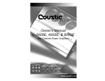
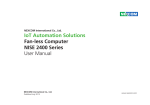
226 LINCOLN STREET
ALLSTON, MA 02134
TEL: (617) 562-4054
FAX: (617) 562-4013
EMAIL: [email protected]
WEBSITE: www.HDM-Sys.com
User’s Manual
Table of Contents:
Introduction
Safety First–Before You Install Your Charger
Warnings
Battery Types and Sizes
Installation–On-Board Chargers
Connections–Portable Chargers
Connections–On-Board Chargers
Operating the Charger
Charger Maintenance
Troubleshooting
Limited Warranty
General Specifications
2
2
3
4
4
4
5
6
8
8
9
10
INPUT
FUSE (A)
WIRE (AWG)
FUSE (A)
14
15
12
10
14
15
12
20
14
15
12
40
12
20
10
60
14
15
12
10
14
15
12
10
14
15
12
20
12
20
10
40
14
15
12
10
12
20
12
20
14
15
12/12
10/10
14
15
12/12
10/20
14
15
12/12
20/20
12
20
12/12
30/30
12
20
12/12
40/40
12
20
12/12
40/20
14
15
12/12
10/10
12
20
12/12
20/20
2.) Safety First – Before You Install the Charger
14
15
12/12/12
20/10/10
This manual contains important safety and operating instructions.
It is important to read this manual thoroughly before installing or
working on the charger.
14
15
12/12/12
20/20/10
14
15
12/12/12
20/20/20
14
15
10/12/12
40/10/10
14
15
12/12/12
40/20/10
12
20
12/12/12
40/20/20
14
15
12/12/12
10/10/10
1.) Introduction
Your ion-X Battery Charger incorporates a patented energy conversion
technology which rapidly chargers the battery while extending battery
life. Utilizing an advanced microprocessor, the charger allows a high
rate of charge to the battery without overheating it, thereby reducing
charge time. There is no loss of electrolyte, virtually no gassing and
no sulfate build-up on the battery plates, all of which contribute to
longer battery life.
2
WIRE (AWG)
OUTPUT
* Input and Output wire sizes apply for distances of up to 4 feet. For greater distances between your
ion-X Battery Charger and your battery(ies), please consult ABYC regulations for appropriate wire sizes.
10.) General Specifications
MODEL
NUMBER
10
WARNINGS
OUTPUT
CURRENT
OUTPUT
VOLTAGE
INPUT
VOLTAGE
(A)
(V)
(V)
1205E
5
12
115 or 230
1210E
10
12
115 or 230
1220E
20
12
115 or 230
1250E
50
12
115 or 230
DANGER – EXTREME CAUTION SHOULD BE TAKEN WHEN
2403E
3
24
115 or 230
2405E
5
24
115 or 230
2410E
10
24
115 or 230
2425E
25
24
115 or 230
4805E
5
48
115 or 230
4810E
10
48
115 or 230
1205/05E
05/05
12
115 or 230
1205/10E
05/10
12
115 or 230
1210/10E
10/10
12
115 or 230
WORKING IN THE VICINITY OF ALL TYPES OF BATTERIES. LEAD
ACID AND AGM BATTERIES EMIT FLAMMABLE GASES DURING
NORMAL OPERATION AND WHILE BEING CHARGED. OPEN
FLAMES, MATCHES, SMOKING MATERIALS OR OTHER MEANS OF
IGNITION SHOULD NOT BE USED NEAR THE BATTERIES. THE AC
POWER SOURCE TO THE CHARGER MUST BE TURNED OFF WHEN
WORKING ON OR DISCONNECTING THE CHARGER TO AVOID
SPARKS. THE BATTERY’S COVER OR A TEMPORARY COVER OF NONCONDUCTIVE MATERIAL SHOULD BE PLACED OVER THE BATTERY
WHEN WORKING NEAR IT TO PREVENT SPARKS FROM
TOOLS BEING DROPPED ON IT.
1215/15E
15/15
12
115 or 230
1220/20E
20/20
12
115 or 230
DANGER – ELECTRICITY CAN KILL – THE AC POWER
1220/2410E
20/10
12
115 or 230
2405/05E
05/05
24
115 or 230
2410/10E
10/10
24
115 or 230
1210/05/05E
10/05/05
12
115 or 230
1210/10/05E
10/10/05
12
115 or 230
1210/10/10E
10/10/10
12
115 or 230
1220/05/05E
20/05/05
12
115 or 230
1220/10/05E
20/10/05
12
115 or 230
1220/10/10E
20/10/10
12
115 or 230
SUPPLY TO THE CHARGER SHOULD ALWAYS INCLUDE AN
EQUIPMENT GROUNDING CONDUCTOR. NEVER USE A TWO-BLADE
TO THREE-BLADE PLUG ADAPTER OR AN EXTENSION CORD WITH
A MALE PLUG HAVING ONLY TWO BLADES. ALWAYS USE AN AC
RECEPTACLE WITH A THREE-BLADE OUTLET AND AN EXTENSION
CORD WITH A THREE BLADE MALE PLUG. ALWAYS UNPLUG OR
TURN OFF THE AC POWER SUPPLY AT THE MAIN DISTRIBUTION
PANEL WHEN WORKING ON THE BATTERY CHARGER. AVOID
WORKING ON OR CONNECTING POWER TO THE CHARGER
WITH WET HANDS OR UNDER WET CONDITIONS.
2405/05/05E
05/05/05
24
115 or 230
IONX ADAPTIVE BATTERY CHARGERS SHOULD ONLY BE USED ON
THE APPROPRIATE OUTPUT VOLTAGE SYSTEMS. PLEASE REFER TO
THE SPECIFICATIONS ON PAGE 10 FOR MORE DETAILS. IMPROPER
USE COULD CAUSE THE BATTERY TO EXPLODE, RESULTING IN FIRE,
PERSONAL INJURY AND DAMAGE TO THE CHARGER.
3
3.) Battery Types and Sizes
9.) Limited Warranty
ion-X Battery Chargers are designed to work with lead acid (flooded)
and absorbent glass mat (AGM) batteries. The ion-X Chargers are also
designed to operate with batteries of any ampere-hour rating. Charge
time will vary depending on the ampere-hour rating of the battery and
the DC output rating of the charger. Chargers for gel cell batteries are
also available; please contact the manufacturer for more details.
HDM Systems Corporation (HDM) offers a limited warranty that covers
defects in workmanship and materials. The limited warranty does not
cover normal wear and tear of the product, including misuse, neglect,
improper installment, or physically damaged units.
4.) Installation – On-Board Chargers
Your standard ion-X battery charger is waterproof, but whenever possible,
it is best to mount the charger in a dry location, not in open areas
exposed to rain, or in locations that are subject to wash down or waterspray. If you have chosen to use the AC input terminal strip option for
your battery charger, then you must install the battery charger in a dry
location. The terminal strip cover is drip-proof, but NOT waterproof.
DO NOT install the charger above batteries where it may be exposed to
corrosive or combustible vapors. DO NOT expose the charger to direct
sunlight if it is to be used continuously for long periods of time.
The charger must be securely fastened to a structural part of the vessel
using the four mounting holes provided in the back plate.
5.) Connections – Portable Chargers
ion-X Battery Chargers can be used as portable chargers. The portable
chargers come complete with an AC power cord and the two DC power
cables with ring terminals per battery bank. Additional protection is provided inside the charger in the AC power circuit to protect it and its components against power surges. Consult the troubleshooting guide on
Page 8 to determine if this AC circuit protection has operated or contact
the manufacturer.
The limited warranty period is 1 year from the date of purchase to you,
the original end-user customer. The limited warranty is non-transferable.
HDM will repair or replace the defective product free of charge, once the
owner has notified HDM of the product defect, and HDM has confirmed
the defect to be within the scope of this limited warranty.
HDM will, at its discretion, use new and/or reconditioned parts in performing limited warranty repairs and building replacement products.
Once HDM has repaired or replaced the product, the warranty period is
not extended, and only the original limited warranty applies. HDM owns
all replaced products and all parts removed from repaired products.
HDM limited warranty does not cover the cost of removal, installation or
troubleshooting of the owner’s electrical system or any repairs done to
the product by parties other than HDM or any of its authorized service
centers. In no event will HDM be liable for any special, direct, indirect,
incidental, or consequential damages, losses, or expenses however arising whether in contract or tort including without restriction any economic
losses of any kind, any loss or damage to property, any personal injury,
any damage or injury arising from or as a result of misuse or abuse or
incorrect installation, integration or operation of the product.
In order to obtain service, the user must first contact HDM and supply
the date of purchase. HDM will provide the user with a Return Material
Authorization (RMA) number and shipping address for product repairs.
Once the user is authorized to return a product for repair, he or she
should send the unit along with proof of purchase, a return address
and contact information.
For more information:
4
TEL: (617) 562-4054
FAX: (617) 562-4013
9
5
FIGURE 1
8.) Charger Maintenance
ion-X
Battery
Charger
ion-x Battery Chargers are self-contained units that require no
maintenance under normal operating conditions. If a fuse fails,
the cause of the failure must be corrected before replacing it and
continuing the use of the charger. To ensure proper charger operation,
the DC battery charger cable connections at the battery terminals must
be periodically inspected for corrosion. Consult your battery’s manual
for cleaning and maintenance instructions.
RED
BLACK
Fuse
AC Power
Breaker
Troubleshooting
FAULT
CHECK
Loss of AC power supply
Check for open AC line fuse or
circuit breaker. Check for wiring
or other causes of fuse failure or
circuit breaker tripping.
Loss of DC output to the
battery
Check for poor battery connections:
check the DC output battery cable
connections at the battery and
at the charger’s DC output terminal
strip. Check for an open DC fuse,
faulty wiring or other causes of
fuse failure.
Internal failure in the
charger
Obtain service from a qualified
service provider or HDM.
AC power supply to the
charger, but LED does not light
Check for poor battery connections.
Power surge may have tripped the
internal AC circuit device. Consult
the manufacturer.
8
Battery
An inline fuse is provided on each positive (red) DC power cable, to
protect the charger from inadvertent reversed polarity. In the event that
your DC power cable fuse blows and requires replacement, refer to the
General Specifications on Page 10 for the appropriate fuse rating to use
with your ion-X Battery Charger.
6.) Connections – On-Board Chargers
Connect the AC cord from the bottom terminal strip of your ion-X
Battery Charger to the corresponding connections of a fuse or circuit
breaker located in the vessel’s AC distribution channel (See General
Specifications on Pages 10-11 for appropriate fuse ratings). If a longer
AC power cord is required, a minimum of American Wire Gauge
(AWG) #14 size marine grade must be used.
Connect the DC power cables from the terminal strip on the ion-X
Battery Charger to the corresponding terminals on the battery(ies).
If the distance from the charger to the battery(ies) is greater than four
feet, then the DC output cables must be increase in size according to
the ABYC Specifications for an allowable 3% voltage drop. Please refer
to Table 1 on page 6 for appropriate AWG wire sizes. The maximum
allowable distance between the charger and the batteries is 14 feet.
5
TABLE 1
Distance to
Batteries - Feet
10-Amps
4–6
6–8
8 – 10
10 – 12
12 – 14
12
12
12
12
12
AWG Wire Size
20-Amps
50-Amps
10
10
10
10
8
6
6
6
6
4
Your ion-X Battery Chargers for onboard installation also comes with
an inline fuse on the positive DC power cable(s). See the General
Specifications on Page 10 for appropriate fuse ratings in the event that
the fuse must be replaced. Additional protection is provided inside the
charger in the AC power circuit to protect it and its components against
power surges. Consult the troubleshooting guide on page 8 to determine
is this AC circuit protection has operated or contact the manufacturer.
B.) Battery Status Indicator (Optional)
The ion-X Battery Charger may come equipped with a battery status
indicator which provides the battery's remaining power based on its
voltage measured at rest. The charger will display the battery status
ONLY when the battery is at rest (i.e. when there is no AC connection
and no load). For accuracy, it is recommended that the battery remain
at rest for a few minutes before reading. Refer to Table 3 below.
TABLE 3
LED C OLOR
Solid Green
Solid Orange
Solid Red
Off
B ATTERY S TATUS
Greater than 85%
50%-85%
25%-50%
Less than 25%
B ATTERY V OLTAGE
Greater than 12.6V
12.2-12.6V
11.9-12.2V
Less than 11.9V
The ion-X Battery Charger generates a moderate amount of heat while
charging. The temperature of the unit may rise up to 35°C/95°F above
the charger environment temperature. Please exercise caution when
handling the charger while in use.
C.) Remote LED Indicator (Optional)
The ion-X Battery Charger may be ordered from the factory with a remote
LED battery status indicator. A separate LED is provided for each bank of
a multi-bank charger. This remote LED will display both the charge status
as well as the battery status, as does the charger itself. HDM will provide
a 15 foot cable to allow for the installation of the remote LED in an area of
the vessel visible to the operator.
A.) Charge Status Indicator
Once installation is complete, the user may monitor the charger’s LED
indicator light to ensure proper charger operation. The ion-x Battery
Charger will accurately display the charge status of the battery ONLY
when plugged into an AC source. Refer to Table 2 below.
D.) All LED Indicators
When the ion-X Adaptive Battery Charger is first connected to the AC
power, the charger requires 30 seconds to initiate its LED functions. Only
after 30 seconds will the LED display precise charging and battery status
measurements.
7.) Operating the Charger
TABLE 2
6
LED C OLOR
C HARGE S TATUS
Solid Green
Flashing Green
Flashing Orange
Flashing Red
100%
80%-100%
50%-80%
Less than 50%
7