1
Installation, Service &
Operation Manual
Spectrum
TM
SoftH2O PRO
Water Softener
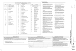
Table of Contents
1.
2.
3.
4.
5.
6.
7.
8.
9.
10.
General Notes
Description & Equipment Adjustments
Components, Features & Functions
Component Contents
Valve User Interface
Installation Instructions
Valve Initial Set-up
Troubleshooting
Cautions
Technical Information
p.2
p.3
p.4
p.5
p.6
p.8
p.10
p.13
p.15
p.16
Spectrum
TM
1. General Notes
The H20 soft duo range are water softeners that are based on one pressure vessel containing resin and an automatic
valve that monitors the amount of water going through the softener and triggers regeneration when the softening
capacity of one pressure vessel expires. This manual is for a range of softeners based on the spectrum 5, 7 and 12
valve going from 25 to 350 litres of resin. Please take a look at the model supplied as this will have an influence on
various parameters for starting up your softener, especially on the programming side. Softeners once installed are low
in maintenance. They need salt in order to operate properly. Please ensure that the brine tank has got a minimum level
of salt at all times. Water softeners will fall under laws and guidelines of the country where it is installed. Please check
the current legal framework in order to be compliant.
Artificially softened water can have a high sodium content which can be unadapted for babies on infant formula, people
on sodium restricted diets or people with risk of heart diseases.
2
2. Description &
Equipment Adjustments
Spectrum
TM
Installation Number
Nominal Capacity
m3 °tH
Valve Serial Number
Inlet Water Hardness
°tH
Tank Size
Treated Water Volume
litres
Resin Type
Outlet Water Hardness
°tH
Salt Quantity per Regeneration
kg
Resin Volume
litres
Regeneration Mode
Volumetric
m3
Regeneration Type
Down Flow Brining
1) Backwash
min
2) Brining & Rinse
min
3) Rapid Rinse
min
4) Brine Tank Refill
min
Electrical Supply
Low Voltage DC Transformer
3
3. Components, Features
& Functions
Component
Features
•
7.5V transformed for SPECTRUM 7 and 12
valves
SPECTRUM
5, 7 or 12
softening
control valve
Media
Pressure
Vessel
24 hours control and monitoring with a timer and meter;
automatically regenerates the media bed once the
capacity of a pressure vessel expires
Cycle Process:
• In service: Once the water is supplied with correct
pressure and flow, the cations contained in hard water
will be replaced by Na+ in regenerants, then the
softening system will supply softened water through its
outlet
• Backwash: When the ion exchange resin has been
exhausted, the resin bed needs to be regenerated.
Before the regeneration of the resin bed, a backwash
step is necessary for two main purposes; removing the
residue in the resin bed and loosening the impacted
resin bed for better regeneration efficiency
• Rinse: Rinse the resin bed to remove the residual
regenerant (salt) after the brining step until the water
from outlet contains no regenerant; rinse could also
compact the resin bed for a better softening effect.
Refill: Refill the brine tank with water to dissolve salt for
the next regeneration
Valve Operation Mode
Softener: Standard water softener operation
Regeneration Mode
Volumetric immediate or delayed with electronic timer
Water Hardness can be adjusted
User can adjust the mixing valve to get desired outlet water
hardness
Display Format
Metric format
NSF 61 and FDA approved SPECTRUM resin
Food grade SPECTRUM softening resin
• NSF 44 tested and certified
• Polyethene material manufactured for the
Food & Beverage industries
Pressure vessel holds the resin and a distribution system
• Light, high pressure resistance
• Strong corrosion resistance
• Polyethylene liner with reinforced fiberglass
Riser Tube &
Distribution
System
Brine Valve
& Tank
TM
Functions
•
GRP valves with great corrosion resistance,
operates with 5.5V DC transformed electrical
power for SPECTRUM 5
Spectrum
A riser tube and distribution system disperse water evenly
through the resin bed
• High pressure resistance
• Prevents the brine tank from overflowing
• Water and salt mix in the brine tank. Salt will dissolve
continuously until the water is saturated by salts
4
Spectrum
TM
4. Component Contents
Please unpack your goods and ensure that all components are included. If something is missing, or damaged you
should contact us immediately. If you are planning to store the components before installation, they should be secured
in a dry area with no risk of freezing as it could affect sensitive components such as plastics becoming brittle or
electronics potentially failing.
4.1. SPECTRUM 5, 7 or 12 Valve
4.2. SPECTRUM Riser Tube
4.3. SPECTRUM Brine Tank
4.4. SPECTRUM Softening Resin
Dimension varies according to model, also includes
brine tube and safety brine valve.
Volume varies according to the model.
5
Spectrum
TM
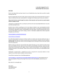
5. Valve User Interface
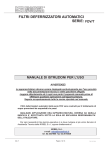
5.1. SPECTRUM 5 Valve
Regeneration Indicator
Bypass
Flow Rate Indicator
Parameter Display
Time Display
Cycle Nº
Next Button (
Regeneration Button ( R )
Up Button (
)
Down Button (
)
)
Blending Valve
Drain Line
Brine Line
Outlet
Inlet
6
Spectrum
TM
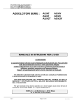
5. Valve User Interface
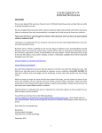
5.2. SPECTRUM 7 & 12 Valve
Cycle Nº
Flow Rate Indicator
Regeneration
Indicator
Time Display
Up Button (
)
Down Button (
)
Next Button (
)
7
Spectrum
TM
6. Installation Instructions
6.1. Prerequisites
The softener needs to be installed onto the mains water supply. Piping has to comply with the regulations of the
country where it is installed.
Your softener will require space for maintenance and operation. Please allow enough room on the top to remove the
valve should it be needed. Also ensure access to the valve is clear in order to be able to visualise or adjust settings on
the electronic board.It should be installed on a dry flat surface.
The softener uses mains power 230-240V AC 50Hz which is transformed into 5.5V or 7.5V DC. Please ensure that the
electrical supply is protected from water or extreme conditions. All electrical installations have to comply with laws of
the country in which it is installed.
Inlet water
The water needs to have a pressure between 2-8 bar and 4-42 degrees. Under 2 bar a booster pump would be
required, over 8 bar, a pressure reducer should be fitted before the softener. It is recommended to add the necessary
pre-filtration before the softener should the T.S.S. (Total suspended solids) go over 1ppm. Suspended solids could
be trapped between the pistons and seals and cause premature wear of your softener internals. They could also clog
prematurely the brine injection system lowering the performance of your system.
You will need two drain connections:
One is for the water rejected to the drain during the regeneration process. This will be connected to the valve, which
is defined as the drainline. Water volume and flow estimations are made in the technical data chart at the end of the
document. The diameter of the flexible drain pipe should be able to accommodate the flow of water to the drain. If the
water does not flow to the drain properly, this will affect the performance of your softener. The drain should never be
higher than the valve height as the pressure will affect the flow of the drain.
Secondly, you will need a connection going from the brine tank overflow to the drain. Although your brine tank is
equipped with a safety brine valve, it is an extra measure to avoid spillage and flooding.
Both the drain line and the overflow should not be higher than the softening valve otherwise, this will affect the
softeners performance.
The Softener should be piped with an external bypass in order to be able to take it off the water line for maintenance
purposes. The soldering on the pipework has to be connected before the water softener as heating could damage
the water softener.
6.2. Assembly
Put the riser tube assembly into the pressure vessel if it has been removed for transport and seal the top in order to
avoid resin getting in the inside of the riser tube. Depending on sizes, the riser tube assembly will either be supplied
with a cone type screen or for bigger sizes, a star type distribution system with a hub and laterals. Ensure that there
is no resin on the tank threads. Once the distributor tube is centred, fill the pressure vessel with water, lubricate the
valve distributor tube o-ring with a 100% silicon lubricant and screw the valve onto the top of the pressure vessel. It is
preferable to use a funnel in order to minimise resin being spread outside the pressure vessel.
CAUTION: RESIN IS SLIPPERY REMOVE ANY EXCESS RESIN THAT MAY HAVE BEEN SPILT
8
Spectrum
TM
6. Installation Instructions
Install the pressure vessel with the valve in a convenient location . Ensure the floor under the brine tank is clear and flat.
Connect the brine tube to the valve on one side and to the safety brine valve included in the brine tank. The piping
should be waterproof as any air entering through the brine line will affect the performance of your system.
Use Teflon® tape if necessary in order to seal between the drain fitting and the outlet flow control.
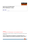
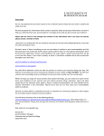
6.3. Connecting
SPECTRUM 5 Valve
SPECTRUM 7 & 12 Valves
6.4. Start Up
Fill the brine tank with water until half of its level. Add salt until the ¼ of the level so that in total the brine tank is ¾ full.
Switch on the electrical power. On units with by-pass, place in by-pass position. Turn on the main water supply. Open
a cold soft water tap nearby and let run a few minutes or until the system is free from foreign material (usually solder)
that may have resulted from the installation. Once clean, close the water tap. Place the by-pass in service position and
let water flow into the pressure vessel. When water flow stops, slowly open a cold water tap nearby and let run until
the air is purged from the unit. Plug the valve to a power source. Once plugged the valve may do a cycle on its own
in order to go to service position.
Start a regeneration by pressing the [R] button on the controller to go through a first complete cycle in order to
initialise the system. This operation can last up to an hour.
Notes: Some items may not be shown depending on timer configuration. The timer will discard any changes and
exit Master Programming Mode if any button is not pressed for sixty seconds.
9
Spectrum
TM
7. Valve Initial Set-Up
7.1. Programming
Notes: Some items may not be shown depending on timer configuration. The timer will discard any changes and exit
Master Programming Mode if any button is not pressed for sixty seconds.
This mode is entered by setting the time to 23:45 and pressing the next button for 8 seconds.
Parameter
Mode of
Regeneration
Option
Description
R-1
Chronometric
R-2
Volumetric immediate
R-3
Volumetric delayed
R-4
Adaptive brining
R-5
Filter: Chronometric
R-6
Filter: Volumetric immediate
R-7
Filter: Volumetric delayed
Choose the most appropriate way of regeneration for your softener. Since our range is volumetric, we recommend R-2
Volumetric immediate or R-3 Volumetric delayed.
Volumetric immediate triggers the regeneration as soon as the capacity of the resin has expired.
Volumetric delayed will trigger the regeneration at the time set in the programming, once the capacity expired.
Parameter
Option
Description
Brine Flow
Direction
t-df
Down flow regeneration
t-uf
Up flow regeneration
For your softener, please choose the Downflow setting.
Parameter
Option
Description
Volume
0.00
Volume of water to be treated
This is the volume in cubic meters your system can soften. The capacity can be determined with the chart in annex 1.
Parameter
Chlorine Level
Option
Description
cl-0
Chlorination: Disabled
cl-1
Chlorination: Weak
cl-2
Chlorination: Average
cl-3
Chlorination: Strong
This is the volume in cubic meters your system can soften. The capacity can be determined with the chart in annex 1.
Parameter
Option
Description
Frequency of
regeneration
or calendar
forcing
F-xx
Volumetric: Calendar forcing every x days
Chronometric: No of days between regenerations
F-of
Volumetric: Calendar forcing disabled
Chronometric: Weekly mode activated
10
Spectrum
TM
7. Valve Initial Set-Up
This is a regeneration override function. Typically, it is used as a “holiday” mode. When there is no regeneration after a
determined number of days, the override will trigger a regeneration. The point is to flush the pressure vessel in order
to avoid bacteria growth.
Parameter
Volume of
treated water
Option
Description
IF xx.x
Volumetric: Calendar forcing every x days
Chronometric: No of days between regenerations
IF-oF
Volumetric: Calendar forcing disabled
Chronometric: Weekly mode activated
Chose the volume of water to treat (Can be found in the capacity calculation chart)
If oF is selected, then the next menu capacity / Hardness mode will be displayed.
Parameter
Option
Description
Resin capacity
C xxx
Resin capacity (m3°tH)
Input the resin capacity indicated by your resin manufacturer (Only displayed in capacity/hardness mode).
Parameter
Option
Description
Water
Hardness
H xx
Water hardness (°tH)
Insert your water hardness (Only displayed in capacity/hardness mode).
Parameter
Option
Description
Water Reserve
o-x.x
Water reserve (m3)
This is a reserve capacity used as a safety buffer in meter delayed mode. It will decrease the chance of having hard
water between the theoretical regeneration time and the set regeneration time. However, it will reduce the efficiency
of the softener.
Parameter
Weekly
Regeneration
Option
Description
J1-1
Monday regeneration activated
J1-o
Monday regeneration disabled
J2-1
Tuesday regeneration activated
J2-o
Tuesday regeneration disabled
J3-1
Wednesday regeneration activated
J3-o
Wednesday regeneration disabled
J4-1
Thursday regeneration activated
J4-o
Thursday regeneration disabled
J5-1
Friday regeneration activated
J5-o
Friday regeneration disabled
J6-1
Saturday regeneration activated
J6-o
Saturday regeneration disabled
J7-1
Sunday regeneration activated
J7-o
Sunday regeneration disabled
11
Spectrum
TM
7. Valve Initial Set-Up
Only displayed in chronometric mode. Allows to choose which days of the week the valve will regenerate.
Parameter
Current Day
Indication
Option
Description
d-1
Monday
d-2
Tuesday
d-3
Wednesday
d-4
Thursday
d-5
Friday
d-6
Saturday
d-7
Sunday
Select the value corresponding to the current day of the week.
Parameter
Option
Description
Length of 1st
cycle
1-xx
Length of cycle in minutes
Length of 2nd
cycle
2-xx
Length of cycle in minutes
Length of 3rd
cycle
3-xx
Length of cycle in minutes
Length of 4th
cycle
4-xx
Length of cycle in minutes
Length of 5th
cycle
5-xx
Length of cycle in minutes
Input the value in minutes according to the cycle time chart.
Parameter
Option
Description
1st regeneration
time slot
xx:H1
Regeneration time
oF:H1
Regeneration time slot disabled
xx:H2
Regeneration time
oF:H2
Regeneration time slot disabled
xx:H3
Regeneration time
oF:H3
Regeneration time slot disabled
xx:H4
Regeneration time
oF:H4
Regeneration time slot disabled
2nd regeneration
time slot
3rd regeneration
time slot
4th regeneration
time slot
You can choose up to 4 regeneration slots in delayed mode, allowing you to minimise the risk of hard water after
expiring capacity.
Parameter
Option
Description
Salt alarm
E
Number of regenerations before starting the alarm
The number of regenerations before displaying the salt alarm display.
12
Spectrum
TM
8. Troubleshooting
8.1. PRO System
Problem
Possible Cause
Possible Solution
A. Controller does not work
1.Power off
2.Transformer is not plugged in
3.Defective power cord
4.Defective transformer
B. Incorrect time of regeneration
1.Power outage causes inaccurate
1. Reset the timer
timing
C. Leaking
1.Loose connections
1. Tighten joints
D. Noisy
1.Air pressure in the system
1. Re-backwash the system to vent air
E. Milk-white water
1.Air exists in the system
1. Turn on the tap to vent air
F. Unsatisfied water hardness
1.Poor raw water quality
2.Time of regeneration is too long
3.Resin disabled
1. Contact your supplier for assistance
2. Reset time of regeneration
3. Re-regeneration or use new resin
1.Water pressure is too low
2.Brine line blocked
3.Injector is blocked
4.Internal control leak
1.Line pressure must be at least 20 psi
2.Clean brine line
3.Clean or replace injector & screen
4.Check piston, seals and spacers
H. Brine container overflow
1. Refill time too long
1. Contact your supplier for assistance
I. Water hardness remains
1. Fail to regenerate automatically
2. Brine concentration is poor
3. Injector is plugged
1. Check power of controller
2. Keep brine tank full of salt
3. Disassemble the injector and clear it
by washing with water
K. Untreated water leakage
during service
1. Improper regeneration
2. Leaking of bypass valve
3. O-ring around riser tube damaged
4. Incorrect regeneration cycle setting
1. Repeat regeneration making certain
that the correct salt dosage is set
2. & 3. Replace O-ring
4. Reset regeneration cycle
G. Softener fails to use salt
1. Switch on power
2. Connect to constant power source
3. Replace cord
4. Replace the transformer
13
Spectrum
TM
8. Troubleshooting
8.2. PRO Valve
Problem
Possible Cause
1.Used or defective batteries
2.Disrupted electric supply
3.Damaged meter cable
A. The system will not regenerate
4.Water meter turbine blocked
5.Defective drive motor
6.Defective electronic board
Possible Solution
1. Replace old batteries
2. Recover the power supply
3. Verify the connection & inspect cable
4. Clean or replace the turbine
5. Replace the drive motor
6. Replace the electronic board
B. There is hard water coming
from the outlet
1.No salt in the brine tank
2.System in bypass position
3.Internal leak in valve
4.Dirty breech
5.Low brine tank refill
6.See symptoms in “A”
1. Refill the brine tank
2. Return the system to service position
3. Change the internal seals
4. Clean the breech
5. Change the two breech seals
6. See resolution in “A”
C. Decrease in pressure and flow
1. Clean or replace the supply line to
the system
1.Iron build up in the water supply
2. Clean the valve and the resin bed.
2.Iron build up in the system
3. Increase backwash time to prevent
3.Levels of iron too high in the feed water
fouling. Specifically install an additional filter to remove iron.
D. High levels of brine present in 1.Clogged drain line
the brine tank
2.Defective cycle time
1. Check and clean the drain line
2. Adjust the cycle times
1.Clogged injectors
2.Clogged drain line
E. The outlet water tastes “salty” 3.Clogged brine valve
4.Defective cycle time
5.Damaged drain flow control
1. Clean the injectors
2. Check the drain line and flow control
3. Clean or replace the piston assembly
4. Adjust the cycle time
5. Change the flow control
F. There is a constant leak during
normal operation
G. Valve regenerates continuously
1. Change the seals
1.Defective seal
2. Change the piston
2.Defective piston
3. Change the piston and the seals and
3.Control valve blocked in regeneration
spacers
4.Defective power head
4. Change the power head
1.Defective power head
1. Change the power head
14
Spectrum
TM
9. Cautions
1. Without reading and understanding the contents of this user manual, DO NOT perform any operations on the
control valve.
2. Strictly prohibit a leaning position when shipping, installing and using this product as this could cause damage.
3. During the regeneration, water from the tap will NOT be softened. It is NOT recommended to use water during
regeneration; otherwise a negative effect on the regeneration result will occur.
4. Initiate a regeneration cycle when the softener has been inactive for a long period of time and then turn on the
tap for several minutes before resuming normal use.
5. Do not disconnect power during service to prevent timer distribution.
6. If water usage or hardness of raw water dramatically increases (compared to the normal usage), then the frequency
of regeneration should increase.
7. Hot water could cause severe damage to the softener system, for water boiler and water heaters users, ensure the
total-run of the piping between the softener and the boiler is not less than 3 metres. It is recommended to install
a check valve between the filter and the boiler if unable to meet the required piping length.
8. The input water pressure must be between 2-8 bar.
9. No chemicals should be present at the inlet and outlet connecting sectors.
10.Besides the system, spare part connection materials are not included in the scope of the manufacturer’s warranty.
11.The required environmental temperature for a softener is 1-42°C. Outside these parameters may cause the
softener to malfunction.
12.Do not apply pressure to the softener.
13.Indoor installation is preferred. Avoid exposure to direct sunlight, radiation from other heating sources and avoid
extreme weather conditions including rain and snow.
14.Use salt granules or tablets designed for softeners.
15.No tools should be used for connecting the plastic parts as over tightening or excessive force could result in damage.
16.If necessary use food grade silica sealant for lubricating rubber O-rings.
17.Only qualified personnel should adjust or remove the adaptor locking clips on the reverse of the valve, as this can tamper
with the valve settings. Should this be required pressure must firstly be discharged from inside the water softener.
15
Spectrum
TM
10. Technical Information
Model (litres of resin)
25
50
75
100
Maximum Operating Temperature (ºC)
42
Minimum Operating Temperature (ºC)
2
Maximum Operating Pressure (bar)
8
Minimum Operating Pressure (bar)
2
150
250
350
Max Flow Rate (m3/hr)
4.5
4.5
4.5
7
7
7
12
Optimal Flow Rate (m3/hr)
1
2
3
4
5.5
8.5
9
Inlet / Outlet (")
¾ BSP
¾ BSP
¾ BSP
1¼ BSP
1¼ BSP
1¼ BSP
1½ BSP
Valve
512
512
512
716
721
721
1236
Drain (")
½ hose fit
½ hose fit
½ hose fit
½ hose fit
¾ BSP
¾ BSP
1 BSP
⅜
⅜
⅜
⅜
½ push fit
½ push fit
½ push fit
Brine Line (")
push fit
push fit
push fit
push fit
Power Requirements (V)
240V or
3V Battery
240V or
3V Battery
240V or
3V Battery
240V at
50H3
240V at
50H3
240V at
50H3
240V at
50H3
Resin Volume (l)
25
50
75
100
150
250
350
Salt Consumption Per Regeneration (kg)
3
6
9
12
18
30
42
Pressure Tank Thread (")
2½
2½
2½
2½
2½
4
4
Vessel Size
09x35
10x54
13x54
14x65
16x65
21x62
24x72
Brine Tank Volume (l)
70
100
140
140
350
500
500
Brine Tank Dimensions (mm)
332 x 332
x 880
382 x 382
x 880
582 x 362
x 904
582 x 362
x 904
ø 740 x
1275
ø 840 x
1335
ø 840 x
1335
Total Height (mm)
1017
1500
1517
1943
1975
1990
2187
Total Weight (kg)
38
67
97
127
191
316
425
16