1
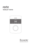
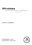
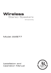
User Guide
www.focusrite.com
IMPORTANT SAFETY INSTRUCTIONS
1.
Read these instructions.
2.
Keep these instructions.
3.
Heed all warnings.
4.
Follow all instructions.
5.
Clean only with dry cloth.
6.
Do not install near any heat sources such as radiators, heat registers, stoves, or other
apparatus (including amplifiers) that produce heat.
7.
Do not defeat the safety purpose of the polarized or grounding-type plug. A polarized plug has
two blades with one wider than the other. A grounding type plug has two blades and a third
grounding prong. The wide blade or the third prong are provided for your safety. If the provided
plug does not fit into your outlet, consult an electrician for replacement of the obsolete outlet.
8.
Protect the power cord from being walked on or pinched particularly at plugs, convenience
receptacles, and the point where they exit from the apparatus.
9.
Only use attachments/accessories specified by the manufacturer.
10.
Use only with the cart, stand, tripod, bracket, or table specified by the manufacturer,
or sold with the apparatus. When a cart is used, use caution when moving the cart/
apparatus combination to avoid injury from tip-over.
11. Unplug this apparatus during lightning storms or when unused for long periods of time.
12. Refer all servicing to qualified service personnel. Servicing is required when the apparatus
has been damaged in any way, such as power-supply cord or plug is damaged, liquid has
been spilled or objects have fallen into the apparatus, the apparatus has been exposed to rain
or moisture, does not operate normally, or has been dropped.
13. No naked flames, such as lighted candles, should be placed on the apparatus.
WARNING: Excessive sound pressure levels from earphones and headphones can cause hearing loss.
WARNING: This equipment must only be connected to USB 2.0-compatible ports.
CAUTION: TO REDUCE THE RISK OF ELECTRIC SHOCK, DO NOT REMOVE
COVER (OR BACK). NO USER-SERVICEABLE PARTS INSIDE.
REFER SERVICING TO QUALIFIED SERVICE PERSONNEL.
The lightning flash with arrowhead symbol, within equilateral triangle,
is intended to alert the user to the presence of uninsulated “dangerous
voltage” within the product’s enclosure that may be of sufficient magnitude
to constitute a risk of electric shock to persons.
The exclamation point within an equilateral triangle is intended to
alert the user to the presence of important operating and maintenance
(servicing) instructions in the literature accompanying the appliance.
2
ENVIRONMENTAL DECLARATION
Compliance Information Statement: Declaration of Compliance procedure
Product Identification: Focusrite Forte
Responsible party: American Music and Sound
Address: 4325 Executive Drive
Suite 300
Southhaven, MS 38672
Telephone: (800) 431-2609
This device complies with part 15 of the FCC Rules. Operation is subject to the following two conditions: (1) This device may not cause
harmful interference, and (2) this device must accept any interference received, including interference that may cause undesired
operation.
For USA
To the User:
1. Do not modify this unit! This product, when installed as indicated in the instructions contained in
this manual, meets FCC requirements. Modifications not expressly approved by Focusrite may void your
authority, granted by the FCC, to use this product.
2. Important: This product satisfies FCC regulations when high quality shielded cables are used to connect
with other equipment. Failure to use high quality shielded cables or to follow the installation instructions
within this manual may cause magnetic interference with appliances such as radios and televisions and
void your FCC authorization to use this product in the USA.
3. Note: This equipment has been tested and found to comply with the limits for a Class B digital device,
pursuant to part 15 of the FCC Rules. These limits are designed to provide reasonable protection against
harmful interference in a residential installation. This equipment generates, uses and can radiate radio
frequency energy and, if not installed and used in accordance with the instructions, may cause harmful
interference to radio communications. However, there is no guarantee that interference will not occur in a
particular installation. If this equipment does cause harmful interference to radio or television reception,
which can be determined by turning the equipment off and on, the user is encouraged to try to correct the
interference by one or more of the following measures:
• Reorient or relocate the receiving antenna.
• Increase the separation between the equipment and receiver.
• Connect the equipment into an outlet on a circuit different from that to which the receiver
is connected.
• Consult the dealer or an experienced radio/TV technician for help.
For Canada
To the User:
This Class B digital apparatus complies with Canadian ICES-003.
Cet appareil numérique de la classe B est conforme à la norme NMB-003 du Canada.
RoHS Notice
Focusrite Audio Engineering Limited has conformed where applicable, to the European Union’s Directive 2002/95/EC on Restrictions
of Hazardous Substances (RoHS) as well as the following sections of California law which refer to RoHS, namely sections 25214.10,
25214.10.2, and 58012, Health and Safety Code; Section 42475.2, Public Resources Code.
3
TABLE OF CONTENTS
IMPORTANT SAFETY INSTRUCTIONS . . . . . . . . . . . . . . . . . . . . . . . . . . . . . . . . . . . . . . . . . . . . . . . 2
ENVIRONMENTAL DECLARATION . . . . . . . . . . . . . . . . . . . . . . . . . . . . . . . . . . . . . . . . . . . . . . . . . . 3
OVERVIEW . . . . . . . . . . . . . . . . . . . . . . . . . . . . . . . . . . . . . . . . . . . . . . . . . . . . . . . . . . . . . . . . . . . . . 5
Introduction . . . . . . . . . . . . . . . . . . . . . . . . . . . . . . . . . . . . . . . . . . . . . . . . . . . . . . . . . . . . . . . . . 5
Features . . . . . . . . . . . . . . . . . . . . . . . . . . . . . . . . . . . . . . . . . . . . . . . . . . . . . . . . . . . . . . . . . . . . 5
Box Contents . . . . . . . . . . . . . . . . . . . . . . . . . . . . . . . . . . . . . . . . . . . . . . . . . . . . . . . . . . . . . . . . 5
System requirements . . . . . . . . . . . . . . . . . . . . . . . . . . . . . . . . . . . . . . . . . . . . . . . . . . . . . . . . . 6
GETTING STARTED . . . . . . . . . . . . . . . . . . . . . . . . . . . . . . . . . . . . . . . . . . . . . . . . . . . . . . . . . . . . . . 7
Software Installation . . . . . . . . . . . . . . . . . . . . . . . . . . . . . . . . . . . . . . . . . . . . . . . . . . . . . . . . . 7
Connecting your Forte . . . . . . . . . . . . . . . . . . . . . . . . . . . . . . . . . . . . . . . . . . . . . . . . . . . . . . . . 8
Input Loom . . . . . . . . . . . . . . . . . . . . . . . . . . . . . . . . . . . . . . . . . . . . . . . . . . . . . . . . . . . . . . . . . . . . 8
Power . . . . . . . . . . . . . . . . . . . . . . . . . . . . . . . . . . . . . . . . . . . . . . . . . . . . . . . . . . . . . . . . . . . . . . . . 8
USB Connection . . . . . . . . . . . . . . . . . . . . . . . . . . . . . . . . . . . . . . . . . . . . . . . . . . . . . . . . . . . . . . . 9
Audio Setup in your DAW . . . . . . . . . . . . . . . . . . . . . . . . . . . . . . . . . . . . . . . . . . . . . . . . . . . . . . 9
Hardware Features . . . . . . . . . . . . . . . . . . . . . . . . . . . . . . . . . . . . . . . . . . . . . . . . . . . . . . . . . . 10
Example Application . . . . . . . . . . . . . . . . . . . . . . . . . . . . . . . . . . . . . . . . . . . . . . . . . . . . . . . . . 11
Forte as a recording interface . . . . . . . . . . . . . . . . . . . . . . . . . . . . . . . . . . . . . . . . . . . . . . . . . . . 11
Using Direct Monitoring . . . . . . . . . . . . . . . . . . . . . . . . . . . . . . . . . . . . . . . . . . . . . . . . . . . . . . . . 12
Connecting Forte to loudspeakers . . . . . . . . . . . . . . . . . . . . . . . . . . . . . . . . . . . . . . . . . . . . . . . . 13
Using Forte Control . . . . . . . . . . . . . . . . . . . . . . . . . . . . . . . . . . . . . . . . . . . . . . . . . . . . . . . . . . . . 14
Input Channels . . . . . . . . . . . . . . . . . . . . . . . . . . . . . . . . . . . . . . . . . . . . . . . . . . . . . . . . . . . . . 14
Outputs . . . . . . . . . . . . . . . . . . . . . . . . . . . . . . . . . . . . . . . . . . . . . . . . . . . . . . . . . . . . . . . . . . . 15
Digital Monitor Mixer . . . . . . . . . . . . . . . . . . . . . . . . . . . . . . . . . . . . . . . . . . . . . . . . . . . . . . . . 15
Settings . . . . . . . . . . . . . . . . . . . . . . . . . . . . . . . . . . . . . . . . . . . . . . . . . . . . . . . . . . . . . . . . . . . 16
Saving and Loading Presets . . . . . . . . . . . . . . . . . . . . . . . . . . . . . . . . . . . . . . . . . . . . . . . . . . 17
Restore Factory Defaults . . . . . . . . . . . . . . . . . . . . . . . . . . . . . . . . . . . . . . . . . . . . . . . . . . . . . 17
Hardware Operation . . . . . . . . . . . . . . . . . . . . . . . . . . . . . . . . . . . . . . . . . . . . . . . . . . . . . . . . . . . . 18
OLED and Mode icons . . . . . . . . . . . . . . . . . . . . . . . . . . . . . . . . . . . . . . . . . . . . . . . . . . . . . . . . 18
Input Mode Menu . . . . . . . . . . . . . . . . . . . . . . . . . . . . . . . . . . . . . . . . . . . . . . . . . . . . . . . . . . . 21
Main Output Mode Menu . . . . . . . . . . . . . . . . . . . . . . . . . . . . . . . . . . . . . . . . . . . . . . . . . . . . . 22
Headphone Output Mode Menu . . . . . . . . . . . . . . . . . . . . . . . . . . . . . . . . . . . . . . . . . . . . . . . . 22
DAW Mode Menu . . . . . . . . . . . . . . . . . . . . . . . . . . . . . . . . . . . . . . . . . . . . . . . . . . . . . . . . . . . . 23
Appendix . . . . . . . . . . . . . . . . . . . . . . . . . . . . . . . . . . . . . . . . . . . . . . . . . . . . . . . . . . . . . . . . . . . . . 24
Forte Control – Factory default settings . . . . . . . . . . . . . . . . . . . . . . . . . . . . . . . . . . . . . . . . . 24
Performance Specifications . . . . . . . . . . . . . . . . . . . . . . . . . . . . . . . . . . . . . . . . . . . . . . . . . . . 24
Physical and Electrical Characteristics . . . . . . . . . . . . . . . . . . . . . . . . . . . . . . . . . . . . . . . . . 26
Troubleshooting . . . . . . . . . . . . . . . . . . . . . . . . . . . . . . . . . . . . . . . . . . . . . . . . . . . . . . . . . . . . 26
4
OVERVIEW
Introduction
Thank you for purchasing the Focusrite Forte, one of the family of Focusrite professional computer
audio interfaces incorporating high quality Focusrite analogue pre-amplifiers. You now have a
professional, compact solution for routing high quality audio to and from your computer.
This User Guide provides a detailed explanation of the hardware to help you achieve a thorough
understanding of the product’s operational features. We recommend that both users who are new
to computer recording, as well as more experienced users, take the time to read through the user
guide so that you are fully aware of all the possibilities that the Focusrite Forte and accompanying
software has to offer. If the main User Guide sections do not provide the information you need, be
sure to consult http://www.focusrite.com/answerbase, which contains a comprehensive collection of
common technical support queries.
Features
The Focusrite Forte hardware interface provides the means for connecting microphones, musical
instruments or line level audio signals to a computer running Mac OS or Windows. The signals at the
physical inputs can be routed to your audio recording software / digital audio workstation (referred
to throughout this user guide as the “DAW”) at up to 24-bit, 192 kHz resolution; similarly, the DAW’s
monitor or recorded output will appear at the unit’s physical outputs.
Audio sources – mics, instruments, etc. - connected to the physical inputs can be recorded in the
DAW and then routed from your DAW to the physical outputs. Forte is equipped with four audio output
channels, which can be connected to an amplifier and speakers, powered monitors, headphones,
DJ or other type of mixer, or any other audio equipment that you wish to use. Although all inputs
and outputs on Forte are routed directly to and from your DAW for recording and playback, you can
configure the routing within your DAW in order to meet your needs. Direct monitoring enables you
hear what you are playing without the effects of computer latency.
For DJs, the two separate outputs makes it possible to monitor the cue mix on headphones via the
headphone output while simultaneously sending the main mix from the speaker output to the sound
system.
Box Contents
Along with your Focusrite Forte you should have:
• Input Loom
• USB cable
• 5 V DC Power Supply (Mains Adaptor)
• Software Download card, with codes for accessing the following on-line resources:
– Forte USB Drivers for Mac and Windows
– Multi-language User Guides
• “Getting Started Guide”
5
System requirements
Mac OS
Apple Macintosh with a USB 2.0-compliant USB port
OS: Mac OS X 10.7 (Lion) or 10.8 (Mountain Lion)
Windows
Windows compatible computer with a USB 2.0 compliant USB port
OS: Windows 7 or Windows 8 (32- or 64-bit)
6
GETTING STARTED
IMPORTANT: PLEASE ENSURE THAT YOU RUN THE INSTALLER
BEFORE CONNECTING THE FOCUSRITE FORTE TO YOUR COMPUTER.
Software Installation
All software required by the Focusrite Forte is available for download from the Focusrite website
http://www.focusrite.com/register. The Software Activation card provided with Forte contains
validation codes which you will need to enter in the downloads area. This procedure ensures that
you will have the most up-to-date software versions.
Can’t get started?
If you have any trouble with this product
do not go back to the place of purchase.
Contact our support team on:
US:
1-855-24-FOCUS
(1-855-243-6287)
Support available Monday - Friday 8am – 6pm (PST)
UK &
+44 1494 462246
International: Support available Monday - Friday 9:30am – 6pm (GMT/BST)
Online:
www.focusrite.com/support
www.novationmusic.com/support
PLACE SERIAL NUMBER STICKER HERE
FA0736-01
1. Using your usual browser, go to http://www.focusrite.com/register/.
2. Select “Forte” from the product range.
3. When prompted, enter your details and the Bundle Codes from the Software Activation Card into
the appropriate fields. Follow the on-screen instructions to initiate the downloads. Save the files to
a suitable location on your computer.
4. When all downloads are complete, navigate to the saved files and click on the filenames to start
the installation. Follow all on-screen instructions carefully from this point.
5. When the installation is complete, you will be asked to restart your computer.
6. After restart, connect Forte to your computer with the USB cable supplied.
Mac OS only:
Your OS should automatically switch the computer’s default audio outputs to be the USB port to
which Forte is connected. To verify this, go to System Preferences > Sound, and ensure that the
input and output are set to Forte. For more detailed setup options on a Mac, open Applications >
Utilities > Audio MIDI Setup.
Windows only:
Your OS should automatically switch the computer’s default audio outputs to be the USB port to
which Forte is connected. To verify this, go to Start > Control Panel > Hardware and Sound >
Sound > Manage Audio Devices and ensure that ‘Default Playback’ and ‘Recording’ are set to
‘Forte’.
7
Connecting your Forte
IMPORTANT: Before you connect Forte to your computer, please complete the software installation according to the instructions above.
This will ensure that the hardware uses the correct drivers and will
prevent unexpected behaviour.
Input Loom
Forte is supplied with an input loom that connects to the INPUTS port on the rear of the unit. The
loom is provided with two female XLR sockets for microphone inputs and two 3-pole (TRS) jack
sockets for line or instrument inputs.
Power
Forte can either be powered directly from the USB connection to a computer or from the supplied
5 V DC, 1 A power supply.
IMPORTANT: The power supply must be used if 48 V phantom power is required. If Forte is
powered directly from the USB port, phantom power will not be available.
IMPORTANT: Operating Forte from a USB port will place the unit in “USB Low-Power mode”.
In this mode, the maximum output levels available from the main and headphone outputs are
limited. If higher output levels are required (e.g., for headphones) then use the 5 V DC power supply
provided.
IMPORTANT: We very strongly recommend that you only use the supplied power supply.
Failure to use this power supply is likely to permanently damage the unit and will also
invalidate your warranty. Power supplies for your Focusrite product can be purchased from your
music dealer if you have lost yours.
8
USB Connection
The Focusrite Forte has a single USB 2.0 port (on the rear panel). Once the software installation is
complete, simply connect Forte to your computer using the USB cable provided. (Note that Forte is a
USB 2.0 device, and thus the USB connection requires a USB 2.0 compatible port on your computer.
It will not operate correctly with USB 1.0/1.1 ports).
Audio Setup in your DAW
Forte is compatible with any Windows-based DAW that supports ASIO or WDM* and any Mac-based
DAW that uses Core Audio. After installing the drivers and connecting the hardware, you can start
using Forte with the DAW of your choice.
*Only compatible with 16-bit audio under WDM.
Please note - your DAW may not automatically select Forte as its default I/O device. In this case, you
must manually select ‘Forte’ (on Mac-based systems) or ‘Focusrite USB2.0 Audio Driver’ (on
PC-based systems) as the driver on your DAW’s Audio Setup* page. Please refer to your DAW’s
documentation (or Help files) if you are unsure where to select the ASIO or Core Audio driver.
Once Forte is set as the preferred Audio Device* in your DAW, Inputs 1 & 2 and Outputs 1 to 4
will appear in your DAW’s Audio I/O preferences. Depending on your DAW, you may need to enable
certain inputs or outputs before use.
*Typical name. Terminology may differ slightly between DAWs.
9
Hardware Features
4
3
2
1
5
6
7
8
9
1. OLED screen – multi-function display providing signal level metering and various menu
options.
2. MODE ICONS – touch-sensitive icons for selecting the Forte’s primary operating modes and
menu navigation.
3. ROTARY CONTROL – for menu navigation and parameter control; incorporates a “push”
function for use with the menus. The rotary control can also be used as the main input gain
and output level control.
4. HEADPHONE SOCKET – plug your stereo headphones in here (¼” TRS jack).
5. KENSINGTON LOCK – for securing your Forte.
6. DC POWER IN – for connection of the supplied 5 V PSU only. Use this socket if you are intending
to use capacitor microphones requiring phantom power.
7. USB PORT - USB 2.0 Type B port, for connecting your Forte to a computer.
8. INPUT SOCKET – connect the supplied input loom to this socket. Note the loom plug has a
latch; ensure that the connector is fully engaged.
9. OUTPUTS - 2 x ¼” TRS jack sockets providing balanced line outputs for connection your
studio monitoring system.
10
Example Application
The Focusrite Forte is ideal for a variety of recording and monitoring applications. A typical
configuration is shown below.
Forte as a recording interface
This setup illustrates the most typical configuration for recording with DAW software on your Mac or
PC. In this case, you might record guitar through Input 1 and vocals through Input 2 into your DAW,
while monitoring the playback from the DAW via headphones or loudspeakers.
Forte is supplied with an input loom, which “breaks out” the multipin input connector to two XLR
female sockets (Mic 1 and Mic 2) and two ¼” TRS jack sockets (Line/Inst 1 and Line/Inst 2). You can
record two inputs at once, and these may be two microphones, two line or instrument inputs, or one
of each. The XLR inputs are intended only for use with microphones. All four inputs are balanced.
11
Connect Forte to your computer with the supplied USB cable and run the Forte Control application.
Click the icons at the top of the input faders to select the type of input for each channel.
• Microphone – select this if you want to use a microphone as the input source. If you are using
a capacitor (condenser) microphone, click the 48V button to supply phantom power to the mic.
Don’t turn this on if you’re using any other type of mic. Only use a capacitor mic if Forte is
powered via its external PSU, not via USB.
• Instrument – select this if you want to connect an instrument (such as a guitar)
• Line – select this if you are connecting a line-level source, such as a synth module.
Using Direct Monitoring
You will frequently hear the term “latency” used in connection with digital audio systems. In the case
of the simple DAW recording application described above, latency will be the time it takes for your
input signals to pass through your computer and audio software. Latency can be a problem for a
performer who wishes to record while monitoring their input signals.
Forte uses “Direct Monitoring”, which overcomes this problem. This is because Forte’s inputs have
their own channels in the two monitoring mixers, and Forte Control will thus route your input signals
directly to the headphone and main monitor outputs. This enables you to hear yourself with near zero
latency – i.e., in “real time” – along with the DAW playback. The input signals to your computer are
not affected in any way by this setting. See “Using Forte Control” on page 14 for more information.
12
Connecting Forte to loudspeakers
Forte has two stereo outputs, one for headphones at the front of the controller, the other for
connection to a studio monitoring system or mixing console. You can use either or both of these, and
derive separate mixes of inputs and DAW outputs for each. The mixes are defined in Forte Control.
Forte’s rear outputs may be used to connect monitoring speakers. These are provided in variablelevel, electronically balanced form on ¼” (6.35 mm) 3-pole (TRS) jacks. Active monitors (i.e.,
modern studio monitor speakers) incorporate internal amplifiers with a volume control, and may be
connected directly. Passive loudspeakers will require a separate stereo amplifier; in this case, the
outputs should be connected to the amplifier’s inputs.
POWERED
MONITORS
TRS JACK
PASSIVE
MONITORS
JACK − PHONO
Typical consumer (hi-fi) amplifiers and small powered monitors will have unbalanced inputs, either
on phono (RCA) sockets, or via a 3.5 mm 3-pole jack plug intended for direct connection to a computer.
In either case, use a suitable connecting cable with ¼” TS (2-pole) jacks at one end.
Professional power amplifiers will generally have balanced inputs (either on 3-pin XLR or 3-pole
(TRS) ¼” (6.35 mm) jack sockets); use a suitable twin-and-screen cable to connect them to the main
outputs of Forte.
The amplifier (either active speakers or separates/hi-fi) is set to give the preferred volume level.
Once set, the Forte knob is the means to control volume level.
NOTE: You run the risk of creating an audio feedback loop if loudspeakers are active at the same time
as a microphone! We recommend that you always turn off (or turn down) monitoring loudspeakers
while recording, and use headphones when overdubbing.
13
Using Forte Control
Forte Control is the application that lets you control all of Forte’s features from a single, convenient GUI.
2
1
19
14
19
9
3
8
4
10
18
15
5 6 7
16
17
11 12 13
Input Channels
14
1.
Input Select – select mic, instrument or line setting for each of the two inputs.
2.
48V – applies 48 V phantom power to the mic inputs only (XLRs), provided that Forte is powered
by the supplied external PSU.
3.
Signal level – each input channel has a bargraph meter to indicate relative signal levels,
with a numerical readout of instantaneous peak level at the top of the meter. The bargraph
segment corresponding to peak level will stay lit for 1 second (time is user-adjustable, see
“Settings” on page 16). The top segments of the meter are coloured red, and signal levels
this high should be avoided. The top of the scale corresponds to 0 dBFS, and digital clipping is
indicated by the red segments of the bargraph illuminating and the numerical field displaying
OVR for 1 second (time is user-adjustable, see “Settings” on page 16).
4.
Input gain – a rotary control operated by the mouse. This parameter may also be controlled
from the Forte hardware controller.
5.
Hi-pass filter [ ] – a switchable hi-pass filter is included; when in circuit it reduces the LF
response below 75 Hz, with an 12 dB/octave slope. This parameter may also be controlled
from the Forte hardware controller.
6.
Pad – a 10 dB pad may be inserted in each channel to reduce sensitivity on the Mic input. This
parameter may also be controlled from the Forte hardware controller.
7.
Phase reverse [ ] – available on all input sources. Inverts the phase of the signal in the input
channel. This parameter may also be controlled from the Forte hardware controller.
8.
Channel linking - the input channels may be linked – e.g., for convenience of handling stereo
sources. Gain, phase reverse, hi-pass filter and pad functions become common. Any offset in
gain between the two channels when Channel Link is selected will be retained. This parameter
may also be controlled from the Forte hardware controller.
Outputs
The two stereo output channels are identical; the left-hand one controls the rear panel main outputs
and the right-hand the front panel headphones output.
Note: Powering Forte via the USB port will place the unit in “USB Low-Power mode”. In this mode,
the maximum output levels available from the main and headphone outputs are limited. If higher
output levels are required (e.g., for headphones) then use the 5 V DC power supply provided.
9.
Signal level - the output meters are identical to those used for input signal metering.
10. Output level – rotary controls adjusted with the mouse. Double-clicking the controls sets a
fixed output level of -30 dBFS. This parameter may also be controlled from the Forte hardware
controller. Note that if powered by USB the maximum output level is limited to -18 dBFS.
11. Dim – reduces the output level by 12 dB. This parameter may also be controlled from the
Forte hardware controller.
12. Mute – mutes the output channel. This parameter may also be controlled from the Forte
hardware controller.
13. Mono – each output can be reconfigured as an L+R mono sum. This parameter may also be
controlled from the Forte hardware controller.
Digital Monitor Mixer
The Speaker Mix and Headphone Mix sections of Forte Control are identical; use the tabs at the top
to select one or the other. Each mixer has six input channels: two from the input channels, and four
from the DAW outputs. The six channels are arranged in three pairs, and the features of each pair
are identical, thus only one is described below. The mixers control the audio mix which is fed to the
outputs, and have no effect on the signals being sent to the DAW for recording.
Clicking on the
tab at the top of the Digital Monitor Mixer opens a block diagram clarifying how
the sources and destinations are routed to and from the Forte, and which section of the GUI controls
what. Click the
tab a second time to return to the main GUI screen.
15
14. Channel faders – control the amount of the relevant signal (input or DAW output pair) in the
output mix. Note that double-clicking the faders sets them to 0 dB.
15. Signal level - the monitor mixer channel meters are identical to those used for input signal
metering.
16. Mutes – each of the six inputs can be individually muted with the red ‘M’ button.
17. Solos – each of the six inputs may be individually soloed with the green ‘S’ button. Soloing
a channel has the effect of muting all other channels, so that only the selected channel is
heard. More than one channel may be soloed if wished. Note that soloing a mixer channel
does not stop any input signals from being fed to the DAW.
18. Stereo linking – the two channels in each pair may be linked for stereo operation. This
commons the functions of gain, mute and solo.
19. Pan controls – it is possible to position the signal in any of the six channels anywhere in the
stereo image. When Stereo linking is On, the pan controls become stereo balance controls.
Settings
Clicking on File > Settings opens the Settings window, where certain global parameters can
be adjusted. These are:
• Meter Clip Hold – this sets the time that the upper (red) section of the bargraph meters remains
illuminated after the signal level reaches digital clipping. The OVR indication at the top of the
meters is also affected by this parameter. The factory default value is 1 second.
• Meter Peak Hold – this sets the time for which the highest single meter segment remains
illuminated, giving a clearer indication of peak levels. The factory default value is 1 second.
• Sample Rate – audio sampling rates of 44.1, 48, 88.2, 96, 176.4 or 192 kHz may be selected. The
factory default value is 48 kHz.
• Buffer size (Windows only) – audio data transfer between Forte and your DAW over the USB link
may be subject to delays, depending on the computer’s processor speed and workload. For this
reason, the data is buffered in the Forte so that none is lost. Audible audio glitches may be an
indication that the buffer size is too small. The buffer size should be set to the lowest value that
does not produce any unwanted audio artefacts. The value may be adjusted in the range 0 – 20
ms; the factory default value is 10 ms. Buffer size for Mac can be accessed from within the DAW.
16
Saving and Loading Presets
If you want, you can store all the mixer parameters as a preset and reload it at a later time. You can
store as many presets as you wish. Click on File > Save As… to open a standard Save As (Windows)
or Save a snapshot file (Mac) dialogue box. Navigate to a suitable location and Save in the usual
manner. The Preset files have the filename extension *.forte.
Loading a previously-saved Preset is the reverse procedure; click on File > Open, navigate to the
required file and click Open.
Restore Factory Defaults
Clicking on File > Restore Factory Defaults resets all Forte Control parameters to default values.
This sets the input levels at minimum, output levels at -30 dBFS and all Digital Monitor Mixer levels
at unity gain. See “Appendix” on page 24 for full list of factory default settings.
17
Hardware Operation
Many of Forte’s main operating features may also be controlled from the hardware controller itself.
The rotary control, colour OLED display and touch icons provide a simple interface which does not
require continuous access to the on-screen Forte Control application.
The default display on the OLED is a bargraph representation, with input channels on the left, main
outputs in the centre and headphones output on the right.
Selecting any of the three main modes via the touch icons – Input, Main and Headphones - cause the
bargraph display to temporarily compress to show additional textual information: with a compressed
display, the two wide bargraphs are always those showing the signal level relevant to the selected
Mode; i.e., if you select Main Output Mode, the inputs and Headphone outputs will continue to be
represented, but as thin bargraphs at the sides of the display.
OLED and Mode icons
1
2
3
4
5
1. OLED – colour multi-function display, showing metering and textual information, depending
on user actions.
18
2. Input Mode
– gives you control of input functions. A short touch will allow Input 1 Gain
to be adjusted with the rotary control, while a second short touch will switch control to Input
2. (Inputs 1 and 2 “toggle” with successive short touches.) A “long” touch opens a menu,
offering additional input-related functions (see “Input Mode Menu” on page 21), but note
that Input 1’s options will be presented if Input 1’s gain was the last to be accessed, and Input
2’s options if Input 2’s gain was last accessed.
Input Controls
Note that if the input loom is not connected to the Forte, an error message will be displayed:
3.
Main Output Mode
– gives you control of main output functions. A short touch will allow
Main Output Level to be adjusted with the rotary control. A “long” touch opens a menu, offering
additional output-related functions (see “Main Output Mode Menu” on page 22).
Main Output Controls 19
4.
Headphones Mode
- gives you control of headphone functions. A short touch will allow
the headphones volume to be adjusted with the rotary control. A “long” touch opens a menu,
offering additional headphone-related functions.
Headphone Controls
5.
DAW Mode
– lets you send commands from the Forte controller to your DAW to control
certain functions. Default commands are PLAY and Horizontal zoom, but these may be redefined. Keyboard shortcuts must be enabled in your DAW for this mode to work. See “DAW
Mode Menu” on page 23.
20
Input Mode Menu
Seven menu options per input are available; use the rotary control to highlight the required option,
and press the rotary control to change the state (all options except TYPE are “switch” functions).
Input Mode Menu
TYPE – selects Mic, Line or Inst as the source for the currently selected input (1 or 2).
48V – duplicates the function of the on-screen 48V button in Forte Control. Note that this option is
“greyed-out” if Forte is being powered via the USB connection; an external PSU is necessary for
phantom power.
HPF - duplicates the function of the on-screen
button.
PHASE REV - duplicates the function of the on-screen
button.
PAD - duplicates the function of the on-screen Pad button.
LINK – this duplicates the function of the on-screen Link button for the input channels.
CLEAR METER & EXIT- this returns the Forte display to the initial gain/metering page, and clears
any “held” bargraph meter segments on both the Forte OLED and the Forte Control GUI.
21
Main Output Mode Menu
Four menu options are available; use the rotary control to highlight the required option, and press
the rotary control to change the state (all options are “switch” functions).
Main Ouput Menu
MUTE- duplicates the function of the on-screen Mute button for the main output channel in Forte
Control.
DIM - duplicates the function of the on-screen Dim button for the main output channel.
MONO– this duplicates the function of the on-screen Mono button for the main output channel.
CLEAR METER & EXIT- this returns the Forte display to the initial gain/metering page, and clears
any “held” bargraph meter segments.
Headphone Output Mode Menu
Headphone Menu
This menu operates in an identical manner to the Main Output Mode Menu.
22
DAW Mode Menu
DAW Mode lets you use the Forte encoder to control various functions of your DAW.
To use DAW Control Mode, first launch your DAW application; ensure that the application is focused
(i.e., the DAW is the “active” window). Select the DAW Control Icon on the Forte controller. Note that
DAW Control Mode will not operate unless your DAW is the active window (in focus) and the DAW icon
on the Forte Controller is lit.
The default commands sent in DAW Control Mode are:
• PLAY/STOP (Press)
• HORIZONTAL ZOOM (Rotate)
However, it is possible to access additional commands to the Press and Rotate functions. To reassign commands, proceed as follows:
1. Press and hold the DAW Icon on the Forte hardware (i.e., a “long” touch) to enter the Mode
Menu. The OLED will show 2 columns, one for Rotate and one for Press.
2.
Use the control knob to scroll through the available options in the first column.
3.
Select the required option by pressing the control knob. The cursor now moves to the second
column, where the procedure may be repeated.
4.
Press the DAW icon again to leave the menu.
5.
The alternative DAW commands will now be available for use.
Note - For DAW Control Mode to function correctly, please ensure your DAW’s Keyboard Shortcuts
are enabled.
If no DAW is detected, an error message will be displayed:
For a full list of supported DAWs and the commands available with each, please see:
www.focusrite.com/downloads?product=forte.
23
Appendix
Forte Control – Factory default settings
Input channels 1 & 2
Source
Line
Gain
0 dB
48 V
Off
HPF
Off
Pad
Off
Phase
Normal
Stereo link
Off
Output channels – main and headphones
Level
-30 dB
Dim
Off
Mute
Unmuted
Mono
Off
Digital Monitor Mixer – Speaker Mix and Headphone Mix
Inputs 1 & 2 levels
0 dB
DAW 1 - 4 levels
0 dB
Panning
Centre
Mutes
Unmuted
Solos
Off
Stereo link
Inputs – Off; DAW 1 & 2 and DAW 3 & 4 - On
Performance Specifications
Real World ADC Dynamic Range
117 dB (A-weighted)
Real World DAC Dynamic Range
118 dB (A-weighted)
Chipset ADC/DAC DNR
120 dB (A-weighted)
Microphone Inputs
Type
Gain Range
RedNet remote controlled pre-amplifier; electronically balanced,
Zin ~1.3k ohms
0 to +75 dB
24
Maximum Input Level for 0 dBFS
+12 ± 0.5 dBu at minimum gain; Rs = 150 ohms, pad off
Minimum Input Level for 0 dBFS
-63 ± 0.5 dBu at maximum gain; Rs = 150 ohms, pad off
Signal-to-Noise ratio
117 dB (A-weighted; Rs = 150 ohms)
Frequency Response
50 Hz to 42 kHz ±0.1 dB; -0.5 dB @ 20 Hz. (Rs = 150 ohms)
THD+N @ -1 dBFS
0.0007% (@ 1 kHz, +11 dBu input, min. gain, 20 Hz – 22 kHz)
Pad attenuation
10 dB
Noise EIN
-128 dBu (60 dB gain, Rs = 150 ohms, 20 Hz – 22 kHz)
Phantom power
48 V; only with external PSU, switchable per channel
Line Inputs
Gain Range
-12 to +42 dB
Maximum Input Level for 0 dBFS
+20 ± 0.5 dBu at minimum gain; pad off
Minimum Input Level for 0 dBFS
-34 ± 0.5 dBu at maximum gain; pad off
Signal-to-Noise ratio
116 dB (A-weighted)
Frequency Response
20 Hz to 20 kHz ±0.2 dB
THD+N @ -1 dBFS
<0.003% (@ 1 kHz, +19 dBu input, min. gain, 20 Hz – 22 kHz)
Instrument Inputs
Gain Range
+14 to +68 dB
Maximum Input Level for 0 dBFS
+10 ± 0.5 dBu at minimum gain
Minimum Input Level for 0 dBFS
-44 ± 0.5 dBu at maximum gain
Signal-to-Noise ratio
111 dB (A-weighted)
Frequency Response
20 Hz to 20 kHz ±0.2 dB
THD+N @ -1 dBFS
<0.003% (@ 1 kHz, +9 dBu input, min. gain, 20 Hz – 22 kHz)
Analogue High-pass filters
Control
Switchable per-channel
Response
12 dB/oct; -6 dB @ 65 ± 3 Hz
Main Outputs
Type
Electronically balanced
Frequency Response
20 Hz to 20 kHz ± 0.1 dB
Signal-to-Noise ratio
118 dB (A-weighted)*
THD + N @ -1 dBFS
<0.0008% (@ 1 kHz, 20 Hz – 22 kHz)
Maximum Output Level
+16 ±0.5 dBu*
Headphone Outputs
Frequency Response
20 Hz to 20 kHz ± 0.1 dB
Signal-to-Noise ratio
116 dB (A-weighted)*
25
THD + N @ -1 dBFS
<0.0008% (@ 1 kHz, 20 Hz – 22 kHz, 10k ohms load)
Maximum Output into 10 k ohms
+9 dBu (+7 dBV)*
Maximum Power into 150 ohms
30 mW
Maximum Power into 32 ohms
27 mW
Output Impedance
<8 ohms
Suitable load Impedance
>32 ohms
Crosstalk
Input to Input
>-90 dB
Output to Output
>-90 dB
Input to Output
>-90 dB
Additional DSP performance
Clock jitter
<250 ps
Supported sample rates
44.1, 48, 88.2, 96, 176.4, 192 kHz
*NOTE - with 5V DC external power supply
Physical and Electrical Characteristics
Analogue Inputs
Connectors
2 x XLR3F (mic); 2 x TRS ¼” jack (line/inst)
Mic/Line/Inst switching
via software
Analogue Outputs
Main outputs
2 x ¼” TRS jacks; electronically balanced
Headphone outputs
1 x ¼” TRS jack; stereo headphone
Other I/O
USB
1 x USB 2.0 Type B connector
Ext DC in
5 V @ 1 A (via supplied PSU only)
Weight and Dimensions
WxHxD
115 x 345 x 171 mm (without connectors)
Weight
Approx 487 g
Troubleshooting
For all troubleshooting queries, please visit the Focusrite Answerbase at
http://www.focusrite.com/answerbase where you will find articles covering numerous troubleshooting examples.
26
27
28