1
LLC7030 Datasheet
Outdoor Luminaire Controller DALI
General operation
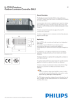
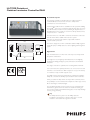
The OLC combines three main functions:
1The controller function receives the incoming commands from the
SC and acts accordingly.
2The OLC switches the Line Output and communicates with the
lamp-driver via the DALI interfaces.
3The monitor function reports data on current, mains voltage, mains
frequency, power factor, burning hours and power consumption of
the connected lamp-driver combination. This information is used to
determine condition of the lamp-driver combination.
A default configured OLC will switch ON its output at maximum level
on power-up.
2/5
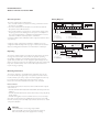
Wiring Diagram
Li
The OLC is equipped with a power line transceiver, which can repeat
messages. The SC monitors and controls the dynamic repeating
functionality centrally. If communication fails between the SC and a
specific OLC, another OLC can be designated dynamically by the SC,
which can repeat messages. The SC will autonomously and continuously
keep track of which OLC’s can be reached directly and which ones
require message repeating.
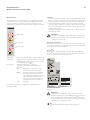
Mounting information
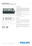
The OLC is designed to be installed inside a luminaire, but can also
be mounted in the pole, gear-trays and separate boxes. If the OLC is
mounted inside a pole it may only be mounted upright. The OLC may
be mounted in any position if the enclosure is IP43 or above.
Please also refer to the installation instruction of the LLC7030.
Released drivers
Currently the lamp-drivers released to interact with the DALI outputs
of the OLC are:
• PHILIPS HID-DV DALI 100/150W SON/CDM with lamps SON and
CDM-TT
• PHILIPS HID-DV DALI Xtreme driver with CPO (Cosmopolis) lamps
60, 90, 140 W
• PHILIPS HF-Regulator II Touch and DALI for PL-L, PL-T, PL-C lamps
Any other component must be validated before it may be used with
the OLC. Contact your local Philips representative about how to obtain
component validation.
Warning
The DALI interface is not using safety isolation
(DA- is internally connected to the Neutral conductor).
Disconnect the main power supply before servicing.
Ni No Lo Ls
Max.
6A
DALI is not using
safety isolation
Lc
DA- DA+ DA- DA+
10 - 11 mm
DALI driver 1
L
DALI driver 2
N
Li = Line input
Ni = Neutral input
No = Neutral output
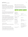
A backup scenario (safeguard mechanism) is available and can be
configured in different ways. Refer to page 4 of this document and the
Starsense Configurator Manual for more information on this topic.
Repeating
0.25 - 2.5 mm2
Filter
Ls = Switched Line output
Lc = Controlled Line input [Photo cell]
0.25 - 2.5 mm2
Filter
Li
Ni No Lo Ls
DALI is not using
safety isolation
Lc
DA- DA+ DA- DA+
Advert
light
Max.
6A
L
N
Li = Line input
Ni = Neutral input
No = Neutral output
DALI driver 1
DALI driver 2
Lo = Line output (not switched)
Ls = Switched Line output
Lc = Controlled Line input [Photo cell]
10 - 11 mm