1
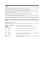
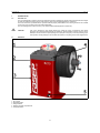
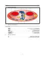
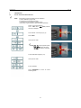
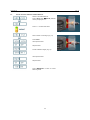
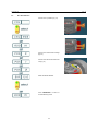
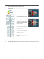
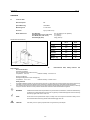
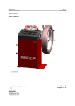
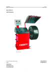
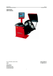
Fasep 2000 srl
Balatron B110, B210: User’s Manual
Rev. 1.2
14 Ottobre 2011
BALATRON B110, B210
USER’S MANUAL
FIG. 1 Balatron 210
FIG. 2 Balatron 110
www.fasep.it
[email protected]
For any information, please contact:
e-mail:
FASEP 2000 srl
Via Faentina 96
50032 Ronta (Fi) Italy
Tel. #39 055 840 3126
Fax #39 055 840 3354
i
Fasep 2000 srl
Balatron B110, B210: User’s Manual
Rev. 1.2
14 Ottobre 2011
WARNING
.This document contains information which is the property of FASEP 2000 srl and all rights are reserved. This manual shall not be
photocopied or reproduced in any way without the prior written consent of FASEP 2000 srl.
.FASEP 2000 srl reserves the right to revise products firmware, software or documentation without obligation to notify any person
or organization. The information contained in this document is subject to change without warning.
.Prior of the installation of the unit described in this manual, user should read this manual carefully to be instructed properly on
installation, use and maintenance of the unit.
.Failing to read this manual and operate accordingly may cause damage to the user or the unit.
.FASEP 2000 srl shall not be responsible for inconvenience, breakdown, accidents due to uncomplete knowledge of this manual
or uncomplete application of recommendations described in this manual.
.FASP 2000 srl shall not be responsible for inconvenience, breakdown, accidents due to unauthorized modifications of the unit, use
of non-original or unauthorized accessories (see Accessories listing in this manual for a list of original accessories available for this
model).
.FASEP 2000 srl shall not be responsible for any inconvenience, breakdown, accidents caused directly or indirectly by not
qualified service. Service to any parts by not qualified persons will void warranty and will void any right of the owner of
the unit.
SYMBOLS AND CONVENTIONS
To speed the retrieval of main information and make easy to understand the instructions, this manual uses the following typing
conventions:
<NAME OF THE PUSH BUTTON>
Used to indicate name of push-buttons on the control panel.
DISPLAY
Used to indicate text or number visible on the displays on the control panel.
☺
ADVICES
Contain useful advices or solutions, evidence d with respect to the rest of the text.
NOTE
Notes contain important information, evidenced to the rest of the text.
WARNING
Warning messages appears corresponding to procedures that, if not properly observed,
may lead to loose of data or cause damage to the unit.
!
CAUTION
Caution messages appears corresponding to procedures that, if not properly observed,
may cause injuries to the user.
ii
Fasep 2000 srl
Balatron B110, B210: User’s Manual
Rev. 1.2
14 Ottobre 2011
TABLE OF CONTENTS
WARNING . . . . . . . . . . . . . . . . . . . . . . . . . . . . . . . . . . . . . . . . . . . . . . . . . . . . . . . . . . . . . . . . . . . . . . . . . . . . . . . . . . . . . . . . . . . ii
SYMBOLS AND CONVENTIONS . . . . . . . . . . . . . . . . . . . . . . . . . . . . . . . . . . . . . . . . . . . . . . . . . . . . . . . . . . . . . . . . . . . . . . . . . ii
TABLE OF CONTENTS . . . . . . . . . . . . . . . . . . . . . . . . . . . . . . . . . . . . . . . . . . . . . . . . . . . . . . . . . . . . . . . . . . . . . . . . . . . . . . . . iii
1
PRESENTATION . . . . . . . . . . . . . . . . . . . . . . . . . . . . . . . . . . . . . . . . . . . . . . . . . . . . . . . . . . . . . . . . . . . . . . . . . . . . 1-1
1.0
Intended Use . . . . . . . . . . . . . . . . . . . . . . . . . . . . . . . . . . . . . . . . . . . . . . . . . . . . . . . . . . . . . . . . . . . . . . . 1-1
1.1
Definitions . . . . . . . . . . . . . . . . . . . . . . . . . . . . . . . . . . . . . . . . . . . . . . . . . . . . . . . . . . . . . . . . . . . . . . . . . 1-1
2
INSTALLATION . . . . . . . . . . . . . . . . . . . . . . . . . . . . . . . . . . . . . . . . . . . . . . . . . . . . . . . . . . . . . . . . . . . . . . . . . . . . .
2.1
Moving the unit . . . . . . . . . . . . . . . . . . . . . . . . . . . . . . . . . . . . . . . . . . . . . . . . . . . . . . . . . . . . . . . . . . . . . .
2.2
Assembling the unit . . . . . . . . . . . . . . . . . . . . . . . . . . . . . . . . . . . . . . . . . . . . . . . . . . . . . . . . . . . . . . . . . .
2.3
Installation . . . . . . . . . . . . . . . . . . . . . . . . . . . . . . . . . . . . . . . . . . . . . . . . . . . . . . . . . . . . . . . . . . . . . . . . .
2.4
Electrical Hookup . . . . . . . . . . . . . . . . . . . . . . . . . . . . . . . . . . . . . . . . . . . . . . . . . . . . . . . . . . . . . . . . . . . .
3
USE THE CONTROL PANEL . . . . . . . . . . . . . . . . . . . . . . . . . . . . . . . . . . . . . . . . . . . . . . . . . . . . . . . . . . . . . . . . . . 3-1
3.1
Meaning of keys at the keyboard . . . . . . . . . . . . . . . . . . . . . . . . . . . . . . . . . . . . . . . . . . . . . . . . . . . . . . . . 3-1
3.2
Meaning of Led Indicators . . . . . . . . . . . . . . . . . . . . . . . . . . . . . . . . . . . . . . . . . . . . . . . . . . . . . . . . . . . . . 3-1
4
CALIBRATION . . . . . . . . . . . . . . . . . . . . . . . . . . . . . . . . . . . . . . . . . . . . . . . . . . . . . . . . . . . . . . . . . . . . . . . . . . . . . .
4.1
How to calibrate the Wheel Balancer . . . . . . . . . . . . . . . . . . . . . . . . . . . . . . . . . . . . . . . . . . . . . . . . . . . . .
4.2
How to check the calibration of Wheel Balancer . . . . . . . . . . . . . . . . . . . . . . . . . . . . . . . . . . . . . . . . . . . .
4.3
ALU-SE Calibration . . . . . . . . . . . . . . . . . . . . . . . . . . . . . . . . . . . . . . . . . . . . . . . . . . . . . . . . . . . . . . . . . .
4-1
4-1
4-2
4-3
5
MEASUREMENT AND CORRECTION OF UNBALANCE . . . . . . . . . . . . . . . . . . . . . . . . . . . . . . . . . . . . . . . . . . . . .
5.1
Placing the wheel rim on the wheel balancer . . . . . . . . . . . . . . . . . . . . . . . . . . . . . . . . . . . . . . . . . . . . . . .
5.2
How to compensate unbalance of flanges using AFC function . . . . . . . . . . . . . . . . . . . . . . . . . . . . . . . . .
5.3
Input of Rim Dimensions . . . . . . . . . . . . . . . . . . . . . . . . . . . . . . . . . . . . . . . . . . . . . . . . . . . . . . . . . . . . . .
5.4
Detecting and correcting unbalance . . . . . . . . . . . . . . . . . . . . . . . . . . . . . . . . . . . . . . . . . . . . . . . . . . . . .
5.5
How to apply the weight using ALU-SE indicator . . . . . . . . . . . . . . . . . . . . . . . . . . . . . . . . . . . . . . . . . . .
5-1
5-1
5-1
5-2
5-4
5-4
6
HOW TO OPTIMIZE UNBALANCE OF THE WHEEL (Option) . . . . . . . . . . . . . . . . . . . . . . . . . . . . . . . . . . . . . . . . . 6-1
7
HOW TO USE SPLIT WEIGHT FUNCTION . . . . . . . . . . . . . . . . . . . . . . . . . . . . . . . . . . . . . . . . . . . . . . . . . . . . . . . 7-1
8
SPECIAL FUNCTIONS MENU . . . . . . . . . . . . . . . . . . . . . . . . . . . . . . . . . . . . . . . . . . . . . . . . . . . . . . . . . . . . . . . . . .
8.1
Enter in the special functions menu . . . . . . . . . . . . . . . . . . . . . . . . . . . . . . . . . . . . . . . . . . . . . . . . . . . . . .
8.2
Diagnostic program of sensors . . . . . . . . . . . . . . . . . . . . . . . . . . . . . . . . . . . . . . . . . . . . . . . . . . . . . . . . .
8.3
Statistic program . . . . . . . . . . . . . . . . . . . . . . . . . . . . . . . . . . . . . . . . . . . . . . . . . . . . . . . . . . . . . . . . . . . .
8.4
User Setup . . . . . . . . . . . . . . . . . . . . . . . . . . . . . . . . . . . . . . . . . . . . . . . . . . . . . . . . . . . . . . . . . . . . . . . . .
2-2
2-2
2-2
2-2
2-2
8-1
8-1
8-1
8-1
8-2
APPENDIX . . . . . . . . . . . . . . . . . . . . . . . . . . . . . . . . . . . . . . . . . . . . . . . . . . . . . . . . . . . . . . . . . . . . . . . . . . . . . . . . . 8-3
A:
Technical Data . . . . . . . . . . . . . . . . . . . . . . . . . . . . . . . . . . . . . . . . . . . . . . . . . . . . . . . . . . . . . . . . . . . . . . . . . . . . . . 8-3
B:
Environmental Data, Safety Features and Requirements . . . . . . . . . . . . . . . . . . . . . . . . . . . . . . . . . . . . . . . . . . . . . 8-3
C:
Errors and Malfunctions recognized by the Computer . . . . . . . . . . . . . . . . . . . . . . . . . . . . . . . . . . . . . . . . . . . . . . . . 3-1
iii
Fasep 2000 srl
Balatron B110, B210: User’s Manual
Rev. 1.2
14 Ottobre 2011
1
PRESENTATION
1.0
Intended Use
This unit is designed to measure and correct static and dynamic unbalance of vehicle wheel, the dimension and weight
of which are within the working range of the machine (see “Technical Data”appendix for reference)
This unit is meant for a professional use. Operator shall be properly trained before use. Training Course is not included
in the price of the unit and must be purchased separately.
This unit is designed for indoor use only ( see “Environmental Data”appendix for reference).
!
CAUTION
1.1
Definitions
This unit is designed to spin vehicle wheels only, within the range of dimensions and weight
approved (see “Technical Data”appendix for reference). Special adaptors suit this purpose. Do not
attempt to use the machine to spin anything else. Unproper locking may cause the part being spun
to be ejected, causing damage to the unit itself, the operator or anything in the in the neighborhood.
1. 3D console
2. Nameplate label
3. Flange holders
4. Weights and tolls compartments
5. Foot-pedal brake
1-1
Fasep 2000 srl
Balatron B110, B210: User’s Manual
2
INSTALLATION
2.1
Moving the unit
WARNING
Rev. 1.2
14 Ottobre 2011
When the unit has to be moved: never lift balancer by motor shaft or by neighborhood of it.
2.2
Assembling the unit
For ease of transportation, the wheel balancer might be disassembled into units. If necessary, assembling instruction are
provided within each package.
2.3
Installation
The wheel balancer must be installed on a firm and level ground.
!
CAUTION
2.4
Electrical Hookup
!
CAUTION
2.4.1
Electrical hookup is to be provided by a qualified electrician.
2.4.2
A fusible wall-mounted switchbox is required at the installation site. This switch should provide on-off control and overload
protection for your wheel balancer only. The switchbox should be fused with time-delay fuse(s) in accordance with the
power rating specified on your wheel balancer.
2.4.3
Electrical connection of the machine should be by plug connectors.
2.4.4
The balancer must be effectively connected to ground. The electric cord is regularly provided with a ground terminal.
2.4.5
Make sure that Power Rate Specifications for your wheel balancer (refer to nameplate on the wheel balancer) comply with
those provided by the external power source.
!
CAUTION
The machine must be secured to the floor. Using four holes in the base and anchor bolts provided.
Failure to follow these instructions can results in damage to unit or create an electrical hazard and
will void warranty.
After electrical hookup has been performed unit is ready to operate. Always observe pertinent safety
precautions when operating the unit (see Appendix tables for an overview of relevant Safety
requirement).
The unit is operated with 12V battery,
Wall mount battery charger is provided.
2-2
Fasep 2000 srl
Balatron B110, B210: User’s Manual
3
Rev. 1.2
14 Ottobre 2011
USE THE CONTROL PANEL
FIG. 7: Panel Balatron 2000
3.1
Meaning of keys at the keyboard
These instructions apply to Normal Operating Mode. Other function maybe activated by these keys in other operating modes (see
Special Functions).
<MODE>: . . . . . . . . . . . . . . . . . . . . . . . . . . . . . . . . . . . . . . . . . . . . . . . . To select balancing type: Dynamic-Static-Alu.
<SET>: . . . . . . . . . . . . . . . . . . . . . . . . . . . . . . . . . . . . . . . . . . . . . . . . . . . . . . . . . . . . . . . . . . . . . . . . Confirm selection
<OPER>: . . . . . . . . . . . . . . . . . . . . . . . . . . . . . . . . . . . . . . . . . . . . . . . . . . . . . . . . To select Operator 1 or Operator 2.
<FINE>: . . . . . . . . . . . . . . . . . . . . . . . . . . . . . . . . . . . . . . . . . . . . . . . . . . . . . . . . . . . . . . . . . . To select reading scale.
<FUNC>: . . . . . . . . . . . . . . . . . . . . . . . . . . . . . . . . . . . . . . . . . . . . . . . . . . . . . . . . . . . . . . . To select specific functions
<START-STOP>: . . . . . . . . . . . . . . . . . . . . . . . . . . . . . . . . . . . . . . . . . . . . . . . . . . . . . . . . Starts-stops wheel spinning.
6 <DISTANCE -/+>: . . . . . . . . . . . . . . . . . . . . . . . . . . . . . . . . . . . . . . . . . . . . . . . . . . . . . . . Set internal side measure.
7 <WIDTH -/+>: . . . . . . . . . . . . . . . . . . . . . . . . . . . . . . . . . . . . . . . . . . . . . . . . . . . . . . . . . . . . . . . . Set width measure.
8 <DIAMETER -/+> . . . . . . . . . . . . . . . . . . . . . . . . . . . . . . . . . . . . . . . . . . . . . . . . . . . . . . . . . . Set diameter measure.
3.2
Meaning of Led Indicators
1-4: . . . . . . . . . . . . . . . . . . . . . . . . . . . . . . . . . . . . . . . . . . . . . . . . . . . . . . . . . . . . . indicate location of weight required.
2-5: . . . . . . . . . . . . . . . . . . . . . . . . . . . . . . . . . . . . . . . . . . . . . . . . . . . . . . . . . . . . . indicate amount of weight required.
3: . . . . . . . . . . . . . . . . . . . . . . . . . . . . . . . . . . . . . . . . . . . . . . . . . . . . . . . . . . . indicate the application point of weights.
3-1
Fasep 2000 srl
Balatron B110, B210: User’s Manual
Rev. 1.2
14 Ottobre 2011
4
CALIBRATION
4.1
How to calibrate the Wheel Balancer
NOTE
the following symptoms indicate need for calibration:
a) check calibration program fails.
b) constant low or high weight readings.
c) indicated point of unbalance constantly wrong
d) more than 2 spins required to balance wheels repeatedly
Switch on the wheel balancer.
Press <SET> when SOF X.XX (software
version) is displayed.
Place a wheel on the flange ( Fig. 9).
Press <SET>
FIG. 9
Hand spin the wheel
NOTE: ACC EL: impress greater speed.
RED UCE: reduce the speed.
GO OD: the speed is corrected.
Put the calibration weight (Fig. 10).
FIG. 10
Hand spin the wheel
End of calibration.
Press <MODE/ESC> to return to normal
balancing mode.
4-1
Fasep 2000 srl
Balatron B110, B210: User’s Manual
4.2
Rev. 1.2
14 Ottobre 2011
How to check the calibration of Wheel Balancer
Switch on the wheel balancer.
Press <SET> when SOF X.XX (software
version) is displayed.
Press <+/-> to select CAL TEST
FIG. 12
Place a wheel on the flange ( Fig. 12).
Press <SET>
Hand spin the wheel
Stop the wheel
Put the calibration weight ( Fig. 13).
FIG. 13
Hand spin the wheel
Stop the wheel
Press <MODE/ESC> to return to normal
balancing mode.
4-2
Fasep 2000 srl
Balatron B110, B210: User’s Manual
4.3
Rev. 1.2
14 Ottobre 2011
ALU-SE Calibration
Put the rod in 0 position (Fig. 15)
FIG. 15
Put the rod in internal side of flange
(Fig.16)
FIG. 16
Put the rod in the internal side of the
rim (Fig.17)
FIG. 17
Select the wheel diameter
Press <MODE/ESC> to return to
normal balancing mode.
4-3
Fasep 2000 srl
Balatron B110, B210: User’s Manual
Rev. 1.2
14 Ottobre 2011
5
MEASUREMENT AND CORRECTION OF UNBALANCE
5.1
Placing the wheel rim on the wheel balancer
5.1.1
Select the cone or flange suitable for the wheel to be balanced. Specific mounting instructions are delivered with each
flange.
NOTE
The operation of centering and tightening of the wheel on the flanges is of basic importance for correct
balancing. Good results depend on proper performance of these procedures.
Clean accurately all cones, shaft and adapter surface before placing the wheel on the wheel balancer.
!
CAUTION
5.2
How to compensate unbalance of flanges using AFC function
NOTE
5.2.1
Always make sure flanges are correctly locked on the motor shaft and wheel is correctly locked on
the flange being used.
This operation allows to put compensate unbalance of flange and other accessories.
Lock the required flange on the shaft without the wheel.
HOW TO TURN ON AFC FUNCTION
HOW TO TURN OFF AFC FUNCTION
Remove the flange.
The ZERO led blinking.
The ZERO led switch off.
The ZERO led is on.
5-1
Fasep 2000 srl
Balatron B110, B210: User’s Manual
5.3
Rev. 1.2
14 Ottobre 2011
Input of Rim Dimensions
NOTE
DOUBLE OPERATOR option (optional for B212): this wheel balancer can be used by 2 operators in the same
time. Everyone can memorizes the dimensions of the wheel to balance with <OPER> button. The machine
memorizes the operating procedure too.
5.3.1
DYNAMIC MODE
Press MODE to select the operating
mode.
Select the wheel diameter.
FIG. 22
Select the distance of the wheel.(Fig.23,
Fig.25)
Select the wheel width.
FIG. 23
5.3.2
STATIC MODE
Press MODE to select the operating
mode.
Select the diameter.
FIG. 25
Select the distance.
Select the width.
5-2
Fasep 2000 srl
Balatron B110, B210: User’s Manual
5.3.3
Rev. 1.2
14 Ottobre 2011
ALU S-1 MODE / ALU S-2 MODE ( Manual input)
Press MODE to select the operating
mode.
Select the wheel diameter.
Insert the internal measure (IN 1) (Fig.
27, Fig.28 ).
FIG. 27
Insert the external measure (IN 2)
(Fig.27, Fig.28)
FIG. 28
5.3.4
ALU SE-1 MODE / ALU SE-2 MODE (Automatic input - optional)
Press MODE to select the operating
mode
Place the rod on the rim (fig. 30)
Wait for the BEEP take-over first
measure.
FIG. 30
Please the rod as in picture 31.
Wait for the BEEP take-over second
measure.
FIG. 31
5-3
Fasep 2000 srl
Balatron B110, B210: User’s Manual
Rev. 1.2
14 Ottobre 2011
5.4
Detecting and correcting unbalance
5.4.1
After setting wheel dimensions, spin the wheel till GOOD appears on the display..
NOTE:
GOOD = correct speed
ACCEL = accelerate (speed is too low)
DECEL = decelerate (speed is too high).
5.4.2
At the end of the spin, stop the wheel. The display will show the weight position and weight requirement to correct the
wheel’s umbalance.
5.4.3
If unbalance shown is 0, press <FINE> to show residual unbalance.
FIG. 33
FIG. 32
NOTE
OPT light blinking after the measurement indicates that static unbalance is exceeding more than 20grs.
Optimization procedure is suggested.
5.5
How to apply the weight using ALU-SE indicator (Option)
Place the weight (Fig. 34).
Turn the wheel to the position ( Fig. 32,
Fig. 33).
///
appears on the
Move the rod until
display ( picture on the left).
Apply the weight ( Fig. 36).
FIG. 35
FIG. 36
5-4
Fasep 2000 srl
Balatron B110, B210: User’s Manual
Rev. 1.2
14 Ottobre 2011
6
HOW TO OPTIMIZE UNBALANCE OF THE WHEEL (Option)
6.1
Measure the unbalance of the rim only. Once the measurement of rim unbalance is calculated, press <FUNC> to enter
optimization function.
Mount the tyre on the rim. After mounting
the tyre, the wheel must be put on the
shaft in the same position as before.
FIG. 38
Hand spin the wheel
Left display (20 in example) indicates
present static unbalance. Right display
(55% in example) indicates possible
reduction of weight in %.
Turn the wheel until SIGN 1 is displayed.
FIG. 39
Mark the rim (12 o’clock).
Turn the wheel until SIGN 2 is displayed.
Mark the tyre (12 o’clock).
Put the two marks together to optimize
unbalance.
6.2
After pressing <SET>, the program return to the measurement of unbalance mode, where an indication of the residual
unbalance values will be given.
6-1
Fasep 2000 srl
Balatron B110, B210: User’s Manual
Rev. 1.2
14 Ottobre 2011
7
HOW TO USE SPLIT WEIGHT FUNCTION
7.1
Measure the unbalance of the wheel. Once the measurement of unbalance is calculated, press <FUNC> to enter split
function.
Turn the wheel until POS 1 is displayed.
Mark the tyre when the first spoke selected is at 12 o’clock.
Turn the wheel until POS 2 is displayed.
Mark the tyre when the second spoke selected is at 12 o’clock.
7.2
The weight in grams for external side is displayed only when the wheel is in a correct position (12 o'clock).
7-1
Fasep 2000 srl
Balatron B110, B210: User’s Manual
8
Rev. 1.2
14 Ottobre 2011
SPECIAL FUNCTIONS MENU
8.1
Enter in the special functions menu
Switch on the wheel balancer. Press <SET> before SOF X.XX will disappear.
CAL
CAL
CAL
LED
SEn
StA
USr
tEc
Ser
Act
tSt
rod
TST
Sor
tiS
Set
Set
nuM
Cod
Calibration of wheel balancer
Control of the calibration of electronic sensors
Calibration of electronic input sensors
Test Led
Diagnostic of sensors
Statistic about the use of machine
User setup
Technical Setup
Serial number
Inserting Activation Codes
8.2
Diagnostic program of sensors
Switch on the wheel balancer. Press <SET> before SOF X.XX will disappear. Select Sen Sor and press <SET>.
rPM
PS1
PS2
tO
PoS
dIS
dIA
Balancing speed
PS1 voltage
PS2 voltage
Encoder is in the zero position
Angle of position sensor(from 0 to 255)
Value of distance sensor
Value of diameter sensor
8.3
Statistic program
Switch on the wheel balancer. Press <SET> before SOF X.XX will disappear. Select Sta tis and press <SET>.
tOt
Total number of spin
SUC
Percent of runs with a good result
c11 0s
Percent of wheels with diameter <11"
from 11 to 17
Percent of wheels with the indicated diameter
]17 0s
Percent of wheels with diameter >17"
CAL
Number of calibrations
8.4
User Setup
Switch on the wheel balancer. Press <SET> before SOF X.XX will disappear. Select USa SET and press <SET>.
ScA LE
Cut oFF
Uni Out
Uni Umb
Fin AL
biP
EME StP
Cou Er
rod in
rod out
STE P
PNE U
SCR EEN
VOI CE
Snr
Tim er
Fas t
APS
ADM IN
OPT
rES Et
Set 1 or 5 grams step (0.05/0.25 ounces).
Set minimum weight to be displayed
Unit of measure for the width (0=inch, 1=millimeters).
Unit of measure for the weight (0= grams, 1=once).
Display of final (0 = normal, 1 = blink, 2= Go OD).
Enable/Disable beep in position
Motor brakes in case of emergency stop (On or OFF) (OFF: motor power is cut).
OFF = safety cover is not installed;
On = the motor starts only if the safety cover is closed;
Aut = closing of safety cover the motor starts automatically
Enable/Disable distance input system.
Enable/Disable width input system
Increase distance/width measure.
Enable/Disable PL system.
Screen saver selection from 1 to 5 (0 = disable).
Enable/Disable voice system.
Sensibility to external vibration.
Input system speed.
Enable/Disable fast cycle
Enable/Disable automatic position system.
Enable/Disable Admin mode.
Set minimum tire matching level.
Load Factory Setup.
8-1
Fasep 2000 srl
Balatron B110, B210: User’s Manual
Rev. 1.2
14 Ottobre 2011
APPENDIX
A:
Technical Data
Absorbed power
5W
Speed Balancing
75/125RPM
Measuring time
4-15 seconds
Precision
±1grs (±1/28 ounce)
Wheel dimensions
Rim Diameter
Wheel Diameter (m ax, with cover)
Rim Width (max, with cover)
Wheel Weight (max)
from 8" (200mm) to 26" (650mm)
34" (850mm)
16" (410mm)
70Kg (155Lbs)
Wheel balancer dimensions
B110
B210
L (mm)
1100
1030
L1 (mm)
500
500
P (mm)
340
430
P1 (mm)
550
550
H (mm)
380
940
Weight (kg)
44
65
Fig.24 : Balatron B110/B210 measures
B:
Environmental Data, Safety Features and
Requirements
Environmental Data
[Operating conditions]
This unit is designed for indoor use only.
Relative Humidity: 5 to 80% a 40/
Temperature: 0 to 45/C
[Storage conditions]
Package is designed for indoor storage only.
Relative humidity: 5 at 95% to40/C
Temperature: -25/ to 70/C
1.
2.
Safety Features
The Balance Weights Holder may be removed for servicing. It is secured to the machine body through screws so that only
voluntarily it may be removed. Removal of this protection is therefore restricted to Authorized Service Engineers.
The Control Panel may be removed for servicing. It is secured to the machine body through screws so that only voluntarily
it may be removed. Removal of this protection is therefore restricted to Authorized Service Engineers.
WARNING
FASEP 2000 srl shall not be responsible for any inconvenience, breakdown, accidents caused directly
or indirectly by unauthorized service. Service to any parts by unauthorized engineers will void warranty
and will any right of the owner of the unit.
NOTE
As this unit runs at a speed below 100rpm, a safety cover is not required. However a safety cover is
recommended when balancing wheels with diameter bigger then 20".
!
CAUTION
The safety cover is anyway required when using the motorcycle adapter.
8-2
Fasep 2000 srl
Balatron B110, B210: User’s Manual
1.
2.
3.
4.
5.
6.
7.
8.
9.
10.
C:
Rev. 1.2
14 Ottobre 2011
General Safety Requirement
[before using/servicing this unit]
Read this instruction manual before operating or servicing the wheel balancer.
Make sure electrical power source conforms to requirements shown on nameplate (see also model identification chart for
reference).
Make sure the unit has a stable position and it’s bolted to the ground.
[when using the unit]
Protect power leading to the unit from damage.
When work area is being washed, make sure unit is adequately protected.
Remove all stones and mud lodged in tire treads before balancing the wheel.
Do not touch spinning wheel.
Make sure counterweights are securely attached before checking residual unbalance.
[when servicing the unit]
Make sure power sources are disconnected before service on the unit is performed.
Service to PCB, electrical and mechanical parts should be done only by an Authorized FASEP 2000 Service Center.
Errors and Malfunctions recognized by the Computer
Errors may apply to some model only.
ERR 1
Shaft does not rotate
ERR 16
Calibration memory error
ERR 2
Rotation Direction is wrong
ERR 17
Rod in uncorrected position
ERR 3
Rotation speed is not ready
ERR 18
Excessive weight detected
ERR 4
Rotation speed is wrong (too low or too high)
ERR 19
Reserved
ERR 5
Position Sensor or Position Disk failure
ERR 20
Excessive Deceleration
ERR 6
Safety Safety cover is open
ERR 21
Error in inputting data
ERR 7
Measuring cycle was interrupted
ERR 22
Brake error
ERR 8
Calibration weight was not inserted
ERR 23
Reserved
ERR 9
Activation code not correct
ERR 24
Insufficient air pressure (PL version)
ERR 10
Overflow in calculations
ERR 25
Reserved
ERR 11
Serial number is wrong
ERR 26
Piezo sensor error
ERR 12
Serial number not inserted
ERR 27
Wheel is not securely tightened on the shaft
ERR 13
Reserved
ERR 28
Laser error
ERR 14
Uncorrected password
ERR 29
Reserved
ERR 15
E²prom error
For a complete and updated list of error codes on the machine together with resolution procedure, please visit http://support.fasep.it/kb
3-1