1
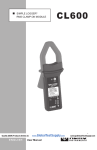
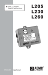
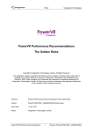
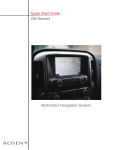
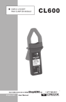
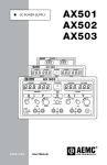
SIMPLE LOGGER® TEMPERATURE MODULE ENGLISH User Manual L605 Owner’s Record The serial number for the Models L605 is located on the side of the case. Please record this number and purchase date for your records. SIMPLE LOGGER® MODEL L605 CATALOG #: 2114.17 SERIAL #: _ _______________________________________________ PURCHASE DATE: _________________________________________ DISTRIBUTOR: ____________________________________________ Table of Contents 1. INTRODUCTION................................................................................ 2 1.1 1.2 1.3 1.4 International Electrical Symbols.................................................2 Definition of Measurement Categories......................................3 Receiving Your Shipment...........................................................3 Ordering Information..................................................................3 1.4.1 Accessories and Replacement Parts.............................3 2. PRODUCT FEATURES....................................................................... 4 2.1 Indicators and Buttons...............................................................4 2.2 Inputs and Outputs....................................................................5 2.3 Mounting....................................................................................5 3. SPECIFICATIONS............................................................................. 6 3.1 3.2 3.3 3.4 Electrical Specifications.............................................................6 Mechanical Specifications.........................................................7 Environmental Specifications.....................................................7 Safety Specifications.................................................................7 4. OPERATION..................................................................................... 8 4.1 Software Installation..................................................................8 4.2 Recording Data..........................................................................9 4.3 Using the Software..................................................................10 4.3.1 The Function Command..............................................10 5. MAINTENANCE.............................................................................. 11 5.1 Battery Installation................................................................... 11 5.2 Cleaning................................................................................... 11 APPENDIX A........................................................................................ 12 Importing .TXT Files into a Spreadsheet.........................................12 Opening a Simple Logger .TXT file in Excel............................12 Formatting the Date and Time.................................................13 Repair and Calibration............................................................................15 Technical and Sales Assistance.............................................................15 Limited Warranty....................................................................................16 Warranty Repairs....................................................................................16 CHAPTER 1 INTRODUCTION WARNING These safety warnings are provided to ensure the safety of personnel and proper operation of the instrument. • Read the instruction manual completely and follow all safety information before operating this instrument. • Use caution on any circuit: Potentially high voltages and currents may be present and may pose a shock hazard. • Read the Safety Specifications section prior to using the instrument. Never exceed the maximum voltage ratings given. • Safety is the responsibility of the operator. • For maintenance, use only original replacement parts. • NEVER open the back of the instrument while connected to any circuit or input. • ALWAYS inspect the instrument and lead prior to use. Replace any defective parts immediately. • NEVER use the Model L605 on electrical conductors rated above 30V in overvoltage category III (CAT III). 1.1 International Electrical Symbols This symbol signifies that the instrument is protected by double or reinforced insulation. Use only specified replacement parts when servicing the instrument. This symbol on the instrument indicates a WARNING and that the operator must refer to the user manual for instructions before operating the instrument. In this manual, the symbol preceding instructions indicates that if the instructions are not followed, bodily injury, installation/sample and product damage may result. Risk of electric shock. The voltage at the parts marked with this symbol may be dangerous. Simple Logger® Temperature Module Model L605 1.2 Definition of Measurement Categories Cat. I: For measurements on circuits not directly connected to the AC supply wall outlet such as protected secondaries, signal level, and limited energy circuits. Cat. II: For measurements performed on circuits directly connected to the electrical distribution system. Examples are measurements on household appliances or portable tools. Cat. III: For measurements performed in the building installation at the distribution level such as on hardwired equipment in fixed installation and circuit breakers. Cat. IV: For measurements performed at the primary electrical supply (<1000V) such as on primary overcurrent protection devices, ripple control units, or meters. 1.3 Receiving Your Shipment Upon receiving your shipment, make sure that the contents are consistent with the packing list. Notify your distributor of any missing items. If the equipment appears to be damaged, file a claim immediately with the carrier and notify your distributor at once, giving a detailed description of any damage. Save the damaged packing container to substantiate your claim. 1.4 Ordering Information Simple Logger® Model L605.............................................. Cat. #2114.17 (Temperature – Internal/External Thermistor) Includes software (CD-ROM), 6 ft DB-9 RS-232 serial cable, 9V Alkaline battery and user manual. 1.4.1 Accessories and Replacement Parts Thermistor Probe with Epoxy bead, 6 ft............................... Cat. #2114.19 Thermistor Probe with 4" Stainless Steel Sheath, 6 ft.......... Cat. #2114.20 Order Accessories and Replacement Parts Directly Online Check our Storefront at www.aemc.com/store for availability Simple Logger® Temperature Module Model L605 CHAPTER 2 PRODUCT FEATURES 1 3 PRESS ! (10k @ 25°C) ! RS-232 INPUT 2 LOGGER OPERATION: 1. Press to Start Logging (Logging = Two Blinks) 2. Press to Stop Logging (Stand-By = One Blink) 3. Press & Hold 5 sec. to Shut Off (Off = No Blinks) Warning: All Data will be Deleted! 4 ! Continuous LED Indicates Overload ® INSTRUMENTS 2.1 SIMPLE LOGGER ® TEMPERATURE MODULE L605 (1) Start/Stop Button (3) LED Indicator (2) Inline Connector for External Sensor (4) RS-232 Interface Indicators and Buttons The Simple Logger® has one button and one indicator. Both are located on the front panel. The PRESS button is used to start and stop recordings and to turn the logger on and off. The Red LED indicates the status of the logger: • Single Blink: STAND-BY mode • Double Blink: RECORD mode • Continuously On: OVERLOAD condition • No Blinks: OFF mode Simple Logger® Temperature Module Model L605 2.2 Inputs and Outputs The Model L605 has an inline connector on the left side and an internal thermistor sensor. The right side of the logger has a female 9-pin “D” shell serial connector used for data transmission from the data logger to your computer. 2.3 Mounting Your Simple Logger® is equipped with mounting holes in the base plate tabs for mounting. For less permanent mounting, the Velcro® pads (supplied loose) can be attached to the logger and the surface to which it will be mounted. Simple Logger® Temperature Module Model L605 CHAPTER 3 SPECIFICATIONS 3.1 Electrical Specifications Number of Channels: 1 Measurement Range: -4 to 158°F, -20 to 70°C (Internal) -4 to 212°F, -20 to 100°C (External) Input Connection: Inline Connector Input Impedance: Thermistor type 10kΩ @ 77°F (25°C) Resolution: 8 Bit Change in Temperature vs Range 2.00 95 85 75 65 55 45 35 25 15 5 -5 -1 5 0.00 -1.00 -2 5 Change in Temperature/Range 1.00 Series1 -2.00 Series2 -3.00 Series3 -4.00 Series4 -5.00 Series5 -6.00 -7.00 -8.00 -9.00 Temperature Reference condition: 23°C ± 3K, 20 to 70% RH, Frequency 50/60Hz, No AC external magnetic Field, DC magnetic field ≤ 40A/m, battery voltage 9V ± 10%. Accuracy: 1% of Readings ± 0.25°C Simple Logger® Temperature Module Model L605 Sample Rate: 4096/hr max; decreases by 50% each time memory is full Data Storage: 8192 readings Data Storage Technique: TXR™ Time Extension Recording™ Power: 9V Alkaline NEDA 1604, 6LF22, 6LR61 Battery Life Recording: Up to 1 year of recording @ 77°F (25°C) Output: RS-232 via DB9 connector, 1200 Bps 3.2 Mechanical Specifications Size: 2-7/8 x 2-5/16 x 1-5/8" (73 x 59 x 41mm) Weight (with battery): 5 oz (140g) Mounting: Base plate mounting holes or Velcro® pads Case Material: Polystyrene UL V0 3.3 Environmental Specifications Operating Temperature: -4 to 158°F (-20 to 70°C) Storage Temperature: -4 to 176°F (-20 to 80°C) Relative Humidity: 5 to 95% non-condensing Temperature Influence: 5cts max 3.4 Safety Specifications Working Voltage: EN 61010, 30V, Cat III *All specifications are subject to change without notice Simple Logger® Temperature Module Model L605 CHAPTER 4 OPERATION 4.1 Software Installation Minimum Computer Requirements • • • • • • Windows® 98/2000/ME/NT and XP Processor - 486 or higher 8MB of RAM 8MB of hard disk space for application, 400K for each stored file One 9-pin serial port; one parallel port for printer support CD-ROM drive 1. Insert the Simple Logger® CD into your CD-ROM drive. If auto-run is enabled, the Setup program will start automatically. If auto-run is not enabled, select Run from the Start menu and type in D:\SETUP (if your CD-ROM drive is drive D. If this is not the case, substitute the appropriate drive letter). 2. The Set-up window will appear. Figure 1 Simple Logger® Temperature Module Model L605 There are a several options to choose from. Some options(*) require an internet connection. • Simple Logger, Version 6.xx - Installs the Simple Logger® software to the computer. • *Acrobat Reader - Links to the Adobe® web site to download the most recent version of Adobe® Acrobat Reader. Acrobat Reader is required for viewing PDF documents supplied on the CD-ROM. • *Check for Available Software Updates - Opens the AEMC Software update web site, where updated software versions are available for downloading, if necessary. • View User Guide and Manuals - Opens Windows® Explorer for viewing of documentation files. 3. To install the software, select Simple Logger Software Setup in the top section of the Set-up window, then select Simple Logger, Version 6.xx in the Options section. 4. Click the Install button and follow the on-screen prompts to install the software. 4.2 Recording Data • If the temperature to be measured is not close to the ambient temperature, the response time will be slow. To avoid this, set the Model L605 or the temperature probe where you intend to record for about a half an hour before turning the recorder on. • Press the PRESS button on the top of the logger to begin the recording session. The LED indicator will double-blink to indicate that the recording session has started. • When the recording session has been completed, press the PRESS button to end the recording. The LED indicator will single-blink to indicate the recording session has ended and the logger is in Stand-by. • Connect the logger to the computer for data downloading. See the User Guide on the CD-ROM for downloading. Simple Logger® Temperature Module Model L605 4.3 Using the Software Launch the software and connect the RS-232 cable from your computer to the logger. NOTE: The first time the program is launched you will need to select a language. Select Port from the menu bar and select the Com port (COM 1, 2 3 or 4) you will be using (see your computer manual). Once the software automatically detects the baud rate, the logger will communicate with the computer. (ID number of the logger and number of points recorded displayed). 4.3.1 The Function Command The Function command allows you to select the correct units for the recorded data. When you click on Function, a pull-down window will appear with two choices: °C or °F. This menu will only appear if a logger is connected to the COM port. Simply click and select the proper units from the menu that opens. Future downloads will use the unit selected here for graphing as well. 10 Simple Logger® Temperature Module Model L605 CHAPTER 5 MAINTENANCE 5.1 Battery Installation Under normal conditions, the battery will last up to a year of continuous recording unless the logger is restarted very frequently. In the OFF mode, the logger puts almost no load on the battery. Use the OFF mode when the logger is not in use. Replace the battery once a year in normal use. If the logger will be used at temperatures below 32°F (0°C) or is frequently turned on and off, replace the battery every six to nine months. 1. Make sure your logger is turned off (no blinking light) and all inputs are disconnected. 2. Turn the logger upside down. Remove the four Phillips head screws from the base plate, then take off the base plate. 3. Locate the two-wire (red/black) battery connector and attach the 9V battery to it. Make sure that you observe polarity by lining up the battery posts to the proper terminals on the connector. 4. Once the connector is plugged onto the battery, insert the battery into the holding clip on the circuit board. 5. If the unit is not in record mode after installing the new battery, disconnect it and press the button twice then reinstall the battery. 6. Reattach the base plate using the four screws removed in Step 2. Your logger is now recording (LED blinking). Press the PRESS button for five seconds to stop the instrument. NOTE: For long-term storage, remove the battery to prevent discharge effects. 5.2 Cleaning The body of the logger should be cleaned with a cloth moistened with soapy water. Rinse with a cloth moistened with clean water. Do not use solvent. Simple Logger® Temperature Module Model L605 11 APPENDIX A Importing .TXT Files into a Spreadsheet Opening a Simple Logger .TXT file in Excel The following example used with Excel Ver. 7.0 or higher. 1. After opening the Excel program, select “File” from the main menu and then select “Open”. 2. In the dialog box that appears, browse and open the folder where your logger .TXT files are stored. This will be located in C:\Program Files\Simple Logger 6.xx if you accepted the default choice offered by the logger installation program. 3. Next, change the file type to “Text Files” in the field labeled Files of Type. All the .TXT files in the logger directory should now be visible. 4. Double-click on the desired file to open the Text Import Wizard. 5. Review the selections in the first wizard screen and make sure that the following choices are selected: Original Data Type: Delimited Start Import at Row: 1 File Origin: Windows (ANSI) 6. Click the “NEXT” button at the bottom of the Wizard dialog box. The second wizard screen will appear. 7. Click on “Comma” in the Delimiters box. A check mark should appear. 8. Click the “NEXT” button at the bottom of the Wizard dialog box. The third wizard screen will appear. 9. A view of the actual data to be imported should appear in the lower section of the window. Column 1 should be highlighted. In the Column Data Format window, select “Date”. 10. Next, click on “Finish” to complete the process and import the data. 11. The data will now appear in your spreadsheet in two columns (A and B) and will look similar to that shown in Figure A-1. 12 Simple Logger® Temperature Module Model L605 A B 8 Arms 35401.49 3.5 35401.49 5 35401.49 9 35401.49 13.5 35401.49 17 35401.49 20 35401.49 23.5 35401.49 27.5 35401.49 31 35401.49 34.5 35401.49 38 Figure A-1. Sample Data Imported into Excel. Formatting the Date and Time Column ‘A’ contains a decimal number that represents both date and time. Excel can convert this number directly as follows: 1. Click on column ‘B’ at the top of the column to select the data, then click on “Insert” from the main menu and select “Columns” from the drop-down menu. 2. Next, click on column ‘A’ at the top of the column to select the data, then click on “Edit” from the main menu and select “Copy” to copy the entire column. 3. Click on cell 1 of column ‘B’ and then click on “Edit” and select “Paste” to insert a duplicate of column ‘A’ into column ‘B’. This is necessary if you want to show the date and time in two separate columns. 4. Next, click on the top of column ‘A’, then click on “Format” and select “Cells” from the drop-down menu. Simple Logger® Temperature Module Model L605 13 5. In the dialog box that opens, select the “Date” option from the category list on the left. Select the date format you desire and click on “OK” to format the column. 6. Click on the top of column ‘B’, then click on “Format” and select “Cells” from the drop-down menu. 7. In the dialog box that opens, select the “Time” option from the category list on the left. Select the time format you desire and click on “OK” to format the column. Figure A-2 shows a typical spreadsheet with date, time and value displayed. It may be necessary to change the column width to see all the data. A B C 12/02/04 11:45 AM 17 12/02/04 11:45 AM 20 12/02/04 11:45 AM 23.5 12/02/04 11:45 AM 27.5 12/02/04 11:45 AM 31 12/02/04 11:45 AM 34.5 12/02/04 11:45 AM 38 12/02/04 11:45 AM 41.5 12/02/04 11:45 AM 45.5 12/02/04 11:46 AM 49 12/02/04 11:46 AM 52 Figure A-2. Shows Date, Time and Value 14 Simple Logger® Temperature Module Model L605 Repair and Calibration To ensure that your instrument meets factory specifications, we recommend that it be scheduled back to our factory Service Center at one-year intervals for recalibration, or as required by other standards or internal procedures. For instrument repair and calibration: You must contact our Service Center for a Customer Service Authorization Number (CSA#). This will ensure that when your instrument arrives, it will be tracked and processed promptly. Please write the CSA# on the outside of the shipping container. If the instrument is returned for calibration, we need to know if you want a standard calibration, or a calibration traceable to N.I.S.T. (Includes calibration certificate plus recorded calibration data). Ship To: Chauvin Arnoux®, Inc. d.b.a. AEMC® Instruments 15 Faraday Drive Dover, NH 03820 USA Phone:(800) 945-2362 (Ext. 360) (603) 749-6434 (Ext. 360) Fax: (603) 742-2346 or (603) 749-6309 E-mail:[email protected] (Or contact your authorized distributor) Costs for repair, standard calibration, and calibration traceable to N.I.S.T. are available. NOTE: You must obtain a CSA# before returning any instrument. Technical and Sales Assistance If you are experiencing any technical problems, or require any assistance with the proper operation or application of your instrument, please call, mail, fax or e-mail our technical support team: Chauvin Arnoux®, Inc. d.b.a. AEMC® Instruments 200 Foxborough Boulevard Foxborough, MA 02035 USA Phone:(800) 343-1391 (508) 698-2115 Fax: (508) 698-2118 E-mail:[email protected] www.aemc.com NOTE: Do not ship Instruments to our Foxborough, MA address. Simple Logger® Temperature Module Model L605 15 Limited Warranty The Simple Logger® Model L605 is warranted to the owner for a period of one year from the date of original purchase against defects in manufacture. This limited warranty is given by AEMC® Instruments, not by the distributor from whom it was purchased. This warranty is void if the unit has been tampered with, abused or if the defect is related to service not performed by AEMC® Instruments. For full and detailed warranty coverage, please read the Warranty Coverage Information, which is attached to the Warranty Registration Card (if enclosed) or is available at www.aemc.com. Please keep the Warranty Coverage Information with your records. What AEMC® Instruments will do: If a malfunction occurs within the one-year period, you may return the instrument to us for repair, provided we have your warranty registration information on file or a proof of purchase. AEMC® Instruments will, at its option, repair or replace the faulty material. REGISTER ONLINE AT: www.aemc.com Warranty Repairs What you must do to return an Instrument for Warranty Repair: First, request a Customer Service Authorization Number (CSA#) by phone or by fax from our Service Department (see address below), then return the instrument along with the signed CSA Form. Please write the CSA# on the outside of the shipping container. Return the instrument, postage or shipment pre-paid to: Ship To: Chauvin Arnoux®, Inc. d.b.a. AEMC® Instruments 15 Faraday Drive • Dover, NH 03820 USA Phone:(800) 945-2362 (Ext. 360) (603) 749-6434 (Ext. 360) Fax: (603) 742-2346 or (603) 749-6309 E-mail:[email protected] Caution: To protect yourself against in-transit loss, we recommend you insure your returned material. NOTE: You must obtain a CSA# before returning any instrument. 16 Simple Logger® Temperature Module Model L605 04/07 99-MAN 100213 v8 Chauvin Arnoux®, Inc. d.b.a. AEMC® Instruments 15 Faraday Drive • Dover, NH 03820 USA • Phone: (603) 749-6434 • Fax: (603) 742-2346 www.aemc.com