1
P60 Agile P16x
Technical Manual
P161, P162, P163
Feeder protection
Platform Hardware Version : 0
Platform Software Version : A
Publication Reference
: P16x/EN M/C
© - ALSTOM 2014. All rights reserved. Information contained in this document is indicative only. No representation or warranty is given or should be relied on that
it is complete or correct or will apply to any particular project. This will depend on the technical and commercial circumstances. It is provided without liability and is
subject to change without notice. Reproduction, use or disclosure to third parties, without express written authority, is strictly prohibited.
P16x
P16x/EN M/B
Technical Manual
- 2/479 -
Technical Manual
P16x
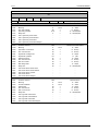
Contents
1
Introduction ............................................................................................................................................... 7
1.1
1.2
1.3
1.4
1.5
1.6
2
Operation of P60 Agile .............................................................................................................................. 24
2.1
2.2
2.3
2.4
3
P60 Agile – General Outline ............................................................................................................. 7
Human machine interface (HMI) ...................................................................................................... 7
Functional scope ............................................................................................................................. 8
1.3.1
Hardware and Software equipment ............................................................................................ 8
Diagnostics and Monitoring .............................................................................................................. 9
Terminal Connections .................................................................................................................... 11
1.5.1
Analogue Inputs for Measurement ............................................................................................ 11
1.5.2
Binary Inputs and Outputs........................................................................................................ 12
1.5.3
Service port .............................................................................................................................. 12
1.5.4
Grounding Instructions ............................................................................................................. 13
1.5.5
Connection Diagrams ............................................................................................................... 15
1.5.6
Communication interfaces (options): ........................................................................................ 16
Mounting instruction ................................................................................................................... 17
Front Panel .................................................................................................................................. 24
Back Panel ................................................................................................................................... 25
2.2.1
Reference to documentation ..................................................................................................... 25
Menu Structure ............................................................................................................................ 26
Start page / Main menu................................................................................................................. 27
2.4.1
Operating ................................................................................................................................. 28
2.4.1.1
Meters ....................................................................................................... 29
2.4.1.2
Synchronizer ............................................................................................... 36
2.4.1.3
Status (SD Card, Debug) .............................................................................. 38
2.4.2
Alarms ..................................................................................................................................... 39
2.4.2.1
Active Alarms .............................................................................................. 39
2.4.2.2
Active Events .............................................................................................. 40
2.4.3
Breaker .................................................................................................................................... 41
2.4.4
Parameters .............................................................................................................................. 41
2.4.4.1
SETUP ....................................................................................................... 42
2.4.4.2
SYSTEM ..................................................................................................... 43
2.4.4.3
PROTECTION .............................................................................................. 44
2.4.4.4
ALARMS..................................................................................................... 44
2.4.4.5
I/O ............................................................................................................ 44
2.4.4.6
BREAKER CONTROL .................................................................................... 45
2.4.4.7
RECORDER ................................................................................................ 45
2.4.5
Recorder (File information and Manual trigger) ........................................................................ 46
2.4.5.1
Event Recorder............................................................................................ 47
2.4.5.2
Fault Recorder ............................................................................................ 48
2.4.5.3
Disturbance Recorder ................................................................................... 51
2.4.6
Settings.................................................................................................................................... 51
2.4.6.1
Display ....................................................................................................... 51
2.4.6.2
Language & Time ......................................................................................... 52
2.4.6.3
User Level (Change-over via touchscreen) ....................................................... 52
2.4.6.4
Reset ......................................................................................................... 53
2.4.7
Info .......................................................................................................................................... 54
System settings ................................................................................................................................... 56
3.1
All Events..................................................................................................................................... 56
3.1.1
Introduction Event System ....................................................................................................... 56
3.1.2
Event list .................................................................................................................................. 56
P16x/EN M/B
- 3/479 -
Technical Manual
P16x
3.2
3.3
3.4
SETUP (Basic device settings)......................................................................................................... 74
3.2.1
User levels................................................................................................................................ 74
3.2.2
Measuring inputs ..................................................................................................................... 78
SYSTEM (System parameters) ........................................................................................................ 79
3.3.1
Nominals (Rated data of the application) ................................................................................. 80
3.3.1.1
Reference Values (Reference values for protection settings) .............................. 80
3.3.1.2
Potential transformers (Rated data of PTs) ..................................................... 83
3.3.1.3
Current transformers (Rated data of CTs) ....................................................... 85
3.3.2
Measuring (Coordination of measuring channels) ..................................................................... 87
3.3.2.1
Power ........................................................................................................ 88
3.3.2.2
Energy ....................................................................................................... 91
3.3.2.3
Differential ................................................................................................. 92
3.3.2.4
PT inputs .................................................................................................... 93
3.3.2.5
Sampler ..................................................................................................... 94
3.3.2.6
Other ......................................................................................................... 95
3.3.3
Counter (Counting functions) ................................................................................................... 96
3.3.4
Filter (Filter functions for measurement, display and event recording) ...................................... 99
3.3.5
Communication (Configuration of interfaces).......................................................................... 102
3.3.5.1
Serial Port 1 ............................................................................................. 102
3.3.5.2
Serial Port 2 ............................................................................................. 103
3.3.5.3
Serial port 2 FOL ....................................................................................... 104
3.3.5.4
Ethernet ................................................................................................... 104
3.3.5.5
Network topology (IEC 61850) .................................................................... 105
3.3.5.6
SNTP ....................................................................................................... 107
3.3.5.7
IEC 61850 ................................................................................................ 108
3.3.5.8
IEC 60870-5-103 ...................................................................................... 109
3.3.6
Graphic (Referencing and selection of displayed measurement values) ................................... 109
PROTECTION ............................................................................................................................. 116
3.4.1
General (Parameter set changeover) ...................................................................................... 117
3.4.2
ANSI 21FL – Fault locator ...................................................................................................... 123
3.4.3
ANSI 25 – Synchronizing ....................................................................................................... 126
3.4.4
ANSI 27 – Undervoltage Protection ........................................................................................ 164
3.4.5
ANSI 27Q – Undervoltage-/Reactive power protection ........................................................... 169
3.4.6
ANSI 27T – Undervoltage Protection; time-dependent ............................................................ 181
3.4.7
ANSI 32 – Directional Power Protection ................................................................................. 189
3.4.8
ANSI 46 – Negative Phase Sequence Current Protection (NPS) ............................................. 206
3.4.9
ANSI 49 – Thermal replica ..................................................................................................... 221
3.4.10
ANSI 50/51 – Overcurrent Protection .................................................................................... 226
3.4.11
ANSI 50BF – Breaker Failure Protection ................................................................................ 241
3.4.12
ANSI 50G/51G – Ground Overcurrent Protection ................................................................... 246
3.4.13
ANSI 51/46 VR – Voltage restraint ........................................................................................ 260
3.4.14
ANSI 59 – Overvoltage Protection .......................................................................................... 262
3.4.15
ANSI 59N/G – Neutral Voltage Displacement (NVD) ............................................................. 267
3.4.16
ANSI 64REF – Restricted Earth Fault Protection .................................................................... 270
3.4.17
ANSI 67 – Directional Overcurrent Protection ........................................................................ 278
3.4.18
ANSI 67G – Directional Ground Overcurrent Protection .......................................................... 296
3.4.19
ANSI 74TC – Trip Circuit Supervision...................................................................................... 312
3.4.20
ANSI 78 – Vector Surge ......................................................................................................... 317
3.4.21
ANSI 79 – Automatic Reclose (AR) ......................................................................................... 321
3.4.22
ANSI 81 – Frequency Protection ............................................................................................ 327
3.4.23
ANSI 81R – RoCoF (df/dt) ..................................................................................................... 334
3.4.24
ANSI 86 – Lockout relay......................................................................................................... 338
3.4.25
ANSI 95i – Harmonics stabiliser ............................................................................................. 343
3.4.26
CLD – Cold Load Detection ..................................................................................................... 346
3.4.27
CTS – Current Transformer Supervision .................................................................................. 349
3.4.28
PTS – Potential Transformer Supervision................................................................................ 354
3.4.29
SOTF – Switch On To Fault .................................................................................................... 367
P16x/EN M/B
- 4/479 -
Technical Manual
P16x
3.5
3.6
3.7
3.8
3.9
3.10
3.4.30
YG – Neutral Admittance Ground Fault Protection ................................................................. 372
ALARM PARAMETERS ................................................................................................................. 380
3.5.1
General .................................................................................................................................. 380
3.5.2
Alarm channels ...................................................................................................................... 380
3.5.3
LEDs (Hardware) ................................................................................................................... 384
I/O PARAMETERS (Binary inputs and binary outputs)...................................................................... 385
3.6.1
General (Settings of voltage range for binary inputs) .............................................................. 385
3.6.2
Binary inputs .......................................................................................................................... 386
3.6.3
Binary outputs........................................................................................................................ 388
3.6.3.1
Shunt Trips (Relay outputs) ........................................................................ 389
3.6.3.2
Lockout Relay (Relay output) ...................................................................... 391
3.6.3.3
Synchron ON (Relay output) ....................................................................... 393
3.6.3.4
Function outputs (Relay outputs) ................................................................. 394
Virtual IO ................................................................................................................................... 394
3.7.1
IEC 61850 subscribers ............................................................................................................ 394
3.7.2
IEC 61850 inputs mapping ..................................................................................................... 396
3.7.3
IEC 61850 outputs mapping ................................................................................................... 398
3.7.4
IEC 61850 device test mode ................................................................................................... 400
3.7.5
Communication events transfer table ..................................................................................... 401
BREAKER CONTROL ................................................................................................................... 402
3.8.1
General .................................................................................................................................. 403
3.8.2
Feedbacks .............................................................................................................................. 404
3.8.3
Breaker Control (Control & Interlocking of switching elements)............................................... 413
3.8.4
Breaker Counter (Counter and events of control operation) ..................................................... 421
RECORDER ................................................................................................................................ 423
3.9.1
Fault Recorder ....................................................................................................................... 423
3.9.2
Disturbance Recorder ............................................................................................................. 423
PLC (Programmable logic control) ................................................................................................. 429
3.10.1
Logic elements ....................................................................................................................... 429
3.10.1.1
AND/OR .................................................................................................. 429
3.10.1.2
NOT (Inverter) .......................................................................................... 432
3.10.1.3
XOR (Exclusive OR) ................................................................................... 433
3.10.1.4
FlipFlops .................................................................................................. 434
3.10.1.5
Counter .................................................................................................... 437
3.10.1.6
Timer ....................................................................................................... 440
3.10.1.7
Timer switch ............................................................................................. 443
4
Maintenance, Servicing and Retesting ...................................................................................................... 447
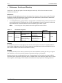
5
Safety Guidelines .................................................................................................................................... 448
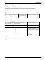
6
Troubleshooting ...................................................................................................................................... 449
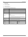
7
Technical Data ........................................................................................................................................ 450
7.1
7.2
7.3
7.4
7.5
7.6
General Technical Data ................................................................................................................ 450
7.1.1
Hardware version v1-2.x........................................................................................................ 450
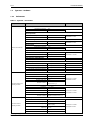
Type tests – Hardware ................................................................................................................ 451
7.2.1
Environment .......................................................................................................................... 451
7.2.2
Electromagnetic capability (EMC) ........................................................................................... 453
Type tests – Software .................................................................................................................. 455
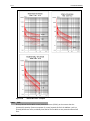
7.3.1
Protective functions – Accuracy .............................................................................................. 455
Binary Inputs and Outputs ........................................................................................................... 469
7.4.1
Binary Inputs ......................................................................................................................... 469
7.4.2
Binary Outputs ....................................................................................................................... 470
Measuring Inputs – Voltage and Current ........................................................................................ 472
Communication Interfaces ........................................................................................................... 473
P16x/EN M/B
- 5/479 -
Technical Manual
P16x
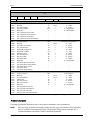
8
CORTEC ORDERING OPTIONS .................................................................................................................. 476
P16x/EN M/B
- 6/479 -
Technical Manual
P16x
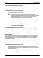
1
Introduction
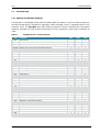
This manual describes the digital protection relays of the P60 Agile product line. This overview presents relay
features, applications and functionalities.
Please see tables 1-1 Section 1.3.1 for detailed information on the protection functions of the P60 Agile
variants.
1.1
P60 Agile – General Outline
The P60 Agile is a numerical relay for use in low, medium and high-voltage systems. With its integrated
protective functions and HMI features, it is an efficient and cost-effective solution for protection and control.
It is equipped with three high-performance micro-processors and offers a comprehensive range of protection
functions for generators, motors (synchronous or asynchronous), transformers, power lines, and substations.
All of the protection functions can be activated and used at any time and without restrictions. In addition, it is
possible to communicate between the P60 Agile and SCADA system via serial or Ethernet ports, with a choice
of data protocols. These features guarantee the highest flexibility during commissioning and operational use.
1.2
Human machine interface (HMI)
Programming and operating a P60 Agile device is easy. A resistive touch screen allows menu navigation.
Graphic representations, events and parameters can be individually created on a PC and transferred to the
P60 Agile device. This customised design allows you to adapt the menus to your requirements.
To guarantee the highest possible safety standards, access to all P60 Agile settings is password protected.
The menu is navigated using the touchscreen from the main menu, which provides access to the submenus
Operating, Alarms & Events, Breaker, Parameters, Recording, Settings and Info.
P16x/EN M/B
- 7/479 -
Technical Manual
P16x
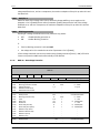
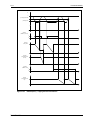
1.3
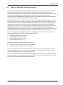
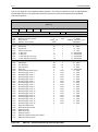
Functional scope
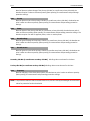
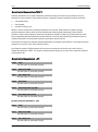
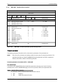
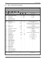
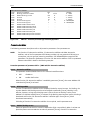
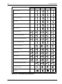
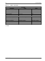
1.3.1 Hardware and Software equipment
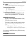
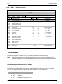
The P60 Agile is a full-fledged one box solutions (OBS) capable of protection, control and metering functions,
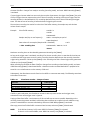
whereas the P60 Agile are intended for applications where switchgear control is managed external to the
protection device. The P60 Agile range offers different protection functions compliant with international
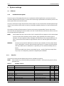
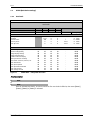
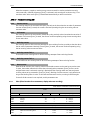
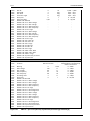
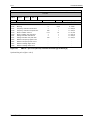
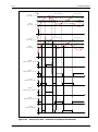
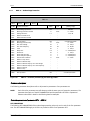
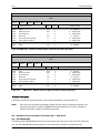
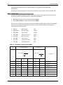
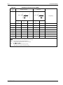
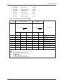
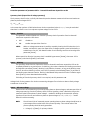
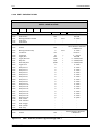
standards. P60 Agile has three variants and protection functions supported by each variant are detailed as
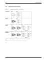
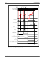
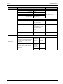
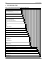
under:Table 1-1
ANSI
21FL
51/51N
51 SEF
50/50N
95i
50BF
67
67N
YN
59N
59
27
27T
27Q
81O
81U
78
81R
32
79
25
CTS
VTS
74
49
32N
46
51V
CLP
46BC
64R
SOTF
P60 Agile variants – Protection function
FUNCTION
Fault Locator
IDMT overcurrent/earth fault protection
Sensitive Earth Fault
Definite time overcurrent/earth fault protection
Inrush Blocking
Breaker Failure protection
Directional overcurrent protection
Directional earthfault protection
Neutral Admittance
Residual Overvoltage
Overvoltage
Undervoltage
Undervoltage,Time dependant (BDEW)
Reactive Power/Undervoltage (BDEW: Fault ride through)
Overfrequency
Underfrequency
Vector surge
Rate of change of frequency (df/dt)
Power protection
Multishot Autoreclose
Check synchronising
CT supervision
VT supervision
Trip circuit monitoring
Thermal Overload
Wattmetric earth fault protection
Negative sequence overcurrent
Voltage dependent overcurrent (voltage restrained)
Cold load pick-up
Broken Conductor
Restricted Earth Fault
Switch On-To-Fault
P16x/EN M/B
P161
P162
•
•
•
•
•
•
•
•
•
•
•
•
•
•
•
•
•
•
•
•
•
•
•
•
•
•
•
•
•
•
•
•
P163
•
•
•
•
•
•
•
•
•
•
•
•
•
•
•
•
•
•
•
•
•
•
•
•
•
•
•
•
•
•
•
•
- 8/479 -
Technical Manual
P16x
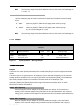
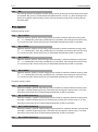
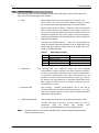
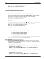
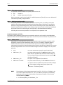
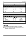
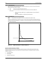
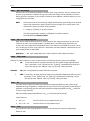
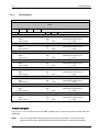
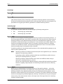
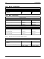
NOTE: Please note that the below table represents the availability of protection functions at the final
development state. At this time, only those protective functions which are described in this manual
are available.
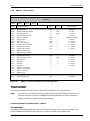
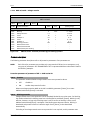
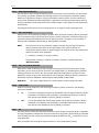
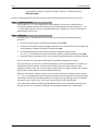
1.4
Diagnostics and Monitoring
All of the three P60 Agile microprocessors have an integrated system for mutual monitoring. Self-supervision
comprises the internal hardware components of P60 Agile, and is done through cyclical requests and
plausibility checks.
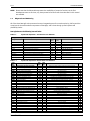
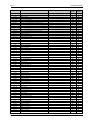
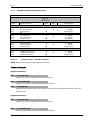
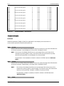
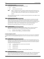
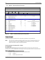
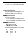
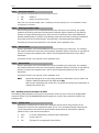
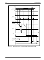
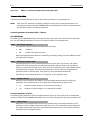
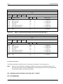
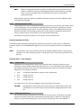
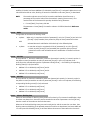
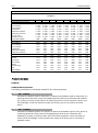
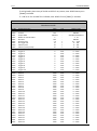
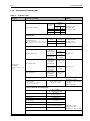
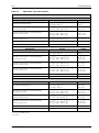
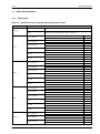
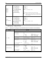
P60 Agile detects the following internal faults:
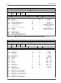
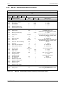
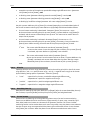
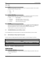
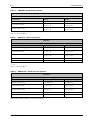
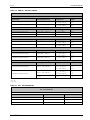
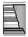
Table 1-2
System self supervision – Functions for error detection
P60 Agile self-supervision description
Type of error
Serial Flash
CU Parameter file
MU Parameter file
GU Parameter file
CU Unit
MU Unit
GU Unit
CAN intern
Binary Inputs ADC
Binary Outputs
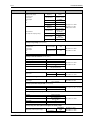
Table 1- 3
Description
Supervision of the Serial Flash
Supervision of the Parameter file
Supervision of the Parameter file
Supervision of the Parameter file
Supervision of the CU processor
Supervision of the MU processor
Supervision of the GU processor
Supervision of the internal communication
Supervision of the ADC for the Binary Inputs
Supervision of the Binary Outputs
Delay
(sec)
1000
1000
1000
1000
1000
1000
1000
1000
100
500
30
30
30
30
10
10
10
1
10
10
Detailed reason
Wrong return value (ID) from driver
CRC checksum error
CRC checksum error
CRC checksum error
No Sign Of Life message
No Sign Of Life message
No Sign Of Life message
CAN Bus Off detected
ADC-Test channel deviation
Wrong feedbacks of the output relays
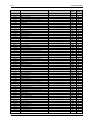
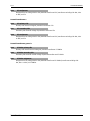
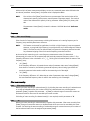
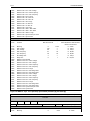
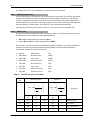
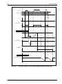
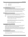
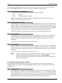
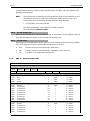
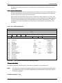
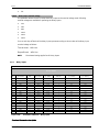
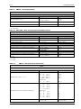
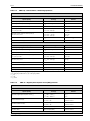
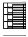
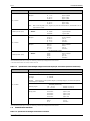
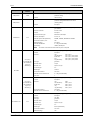
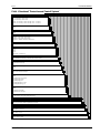
System self supervisison –Events about error detection
Event
No.
E9000
E9001
E9002
E9003
E9004
E9005
E9006
E9007
E9008
E9009
Common alarm of system supervision
Common alarm system total error
CU CPU communication failure
MU CPU communication failure
GU CPU communication failure
ComU CPU communication failure
CU Bad CPU communication
Firmware constellation invalid
Unknown parameter file
Unknown hardware
E9010
E9011
E9012
E9013
E9014
E9015
E9016
E9017
E9018
CU DRAM error
CU Serial Flash error
CU Binary Inputs ADC SPI error
CU Binary Outputs DAC MAX4820 error
CU Serial Port 1 Framing error
CU Analogue Inputs ADC AD7914 error
CU Profibus error
CU SD card error
CU Binary Inputs ADC I²C error
1000
100
500
1000
100
1000
10
-
E9020
E9021
E9022
E9023
CU Parameter file error
MU Parameter file error
GU Parameter file error
ComU Parameter file error
1000
1000
1000
1000
-
E9030
Event system feedback loop detected
1000
E9040
E9041
MU kWh counter crc error
MU EEPROM error
-
Description
P16x/EN M/B
Cycle
(ms)
Cycle
[ms]
1000
1000
1000
1000
1000
1000
1000
1000
Delay
[s]
30
30
30
1
1
1
Active if any of the system supervision events are active
Active if a critical error is active (see column "Prio")
CAN Bus OFF
No CAN messages
No CAN messages
No CAN messages
iCAN Rx/Tx buffer overflow
Firmware incompatible detected by one controller
Unknown parameter file detected by one controller
Unknown hardware detected by one controller
Prio
20
Write-Read-Test error (@ PowerON)
Wrong return value (ID) from driver
Test channel out of range/ Wrong channel address
Wrong feedback signals
Wrong Baudrate or noise
Wrong channel numbers from ADC
VPC3+C Read-Test error
General SD card error
I²C communication error (No ACK, Bus error, etc).
90
90
90
CRC error
CRC error flag set
CRC error flag set
CRC error flag set
60
More than 500 event changes per sec during 60 seconds
CRC error in SRAM (@ WD reset)
Communication error (@ Systemstart)
30
20
20
30
20
20
-
-
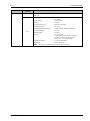
Detailed reason
- 9/479 -
Technical Manual
P16x
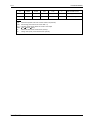
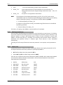
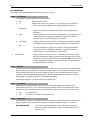
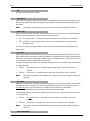
E9042
E9043
E9044
E9045
E9046
E9047
MU Calibration file crc error
MU Overload
MU ADC0 error
MU ADC1 error
MU Battery low alarm
MU Calibration error
E9048
MU Battery defect
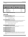
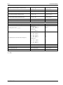
NOTE:
10000
10000
-
30
30
-
CRC error in EEPROM (@ Systemstart)
CPU overload error
Wrong channel numbers from ADC
Wrong channel numbers from ADC
The battery voltage reached critical level
At least one analogue input (U/I) is not calibrated
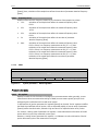
Battery load test is carried out 5s after device reset, thereafter
every 30 days. Event reset by device reset.
System supervision events can only be reset using “ACK”.
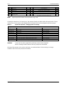
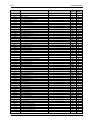
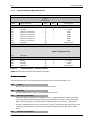
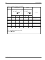
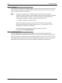
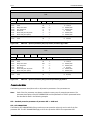
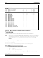
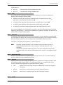
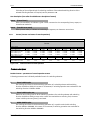
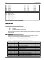
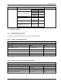
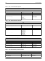
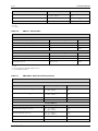
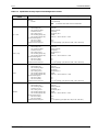
Following the detection of an internal error, the measures listed in the below table will be performed. If these
measures are not successful, event [E9000] will be activated, which can be assigned to any binary output.
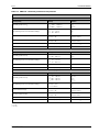
Table 1-4
System self supervision – debugging and error message
P60 Agile self-supervision
Type of error
Serial Flash
CU Parameter file
MU Parameter file
GU Parameter file
CU Unit
MU Unit
GU Unit
CAN intern
Binary Inputs ADC
Binary Outputs
CAUTION:
Measure
Reset the Serial Flash controller
System reboot
System reboot
System reboot
Initialize the CAN controller again
Initialize the CAN controller again
Initialize the CAN controller again
Initialize the CAN controller again
Reset, and reread of ADC (analogue digital converter) values
Reset the relay driver. Write the relay driver again
Activation of event [E9000]
after third repetition
after third repetition
after third repetition
after third repetition
after third repetition
after third repetition
after third repetition
Immediately
after third repetition
after third repetition
In the case of a power supply failure, all binary outputs are de-energised.
While in booting mode the states of all binary outputs are maintained.
All three of the processor units monitor each other, as mentioned above. This monitoring is no longer
available if two of the three processors have failed.
P16x/EN M/B
- 10/479 -
Technical Manual
P16x
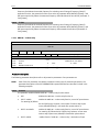
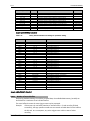
1.5
Terminal Connections
The P60 Agile field interface is via plug-in connectors at the back of the device. This makes device
replacement simple. The terminal blocks are divided into the following groups:
1.5.1
•
Analogue inputs for measurement
•
Binary inputs and outputs
•
Communication interfaces
Analogue Inputs for Measurement
Depending on the device variant and ordering options, the P60 Agile provides a different number of
measurement inputs for current and voltage measurement.
NOTE:
The P60 Agile has been designed to be operated with conventional current and potential
transformers.
All of the possible P60 Agile connections for current and potential transformers are listed below:
* CT1:
•
Three phase current measurement inputs CT1-M/P
•
Optionally, three phase current measurement inputs CT1-M*
•
Single phase current measurement input CT-GND1 (ground current)
•
Three-phase voltage measurement inputs PT1 (e.g. voltage at incoming feeder)
•
Three-phase voltage measurement inputs PT2 (e.g. voltage at busbar 1)
•
Three-phase voltage measurement inputs PT3 (e.g. voltage at busbar 2)
•
Single-phase voltage measurement input PT-GND1 (residual voltage)
separate terminal connections: CT1-M for measuring core and CT1-P for protection core of current transformers
NOTE:
In the case of P60 Agile models with protection (CT1-P) and measurement (CT1-M) transformers,
the protection functions process values of CT1-M for current values which are less than or equal
to 2 x In. For higher current values the measuring values of the CT1-P are used.
In the case of a current transformer failure at CT1-M and a current-carrying CT connected to CT1P, all current protection functions will use current values within the range of 2 x In.
CAUTION:
If any of the voltage measurement inputs (e.g. PT1) is interconnected by V-connection of the
voltage transformers to a power system, the relay terminal “N” must not be connected to
anything.
If combined transformers (combined sensors) are used, the P60 Agile allows connection of feeding
current/voltage:
•
3 current measurement inputs for feeding current
•
3 voltage measurement inputs for feeding voltage
The following values are measured via analogue inputs and displayed:
•
Phase-to-Phase and Phase-to-Ground voltages of incoming feeder, busbar 1 and busbar 2
•
3-phase feeding current (average/maximum)
P16x/EN M/B
- 11/479 -
Technical Manual
P16x
1.5.2
•
Frequencies of all systems (minimum/maximum)
•
Ground current (maximum)
•
Residual voltage
•
Operating hours
Binary Inputs and Outputs
The P60 Agile range offers 18x binary inputs and 12x binary outputs as standard.
1.5.3
Service port
To operate the P60 Agile device using a PC/notebook, there is a USB-A interface located at the front of the
device, and a mini-USB interface on the side. The side interface is useful when the relay is installed in
switchgear where the panel front swings open for access.
P16x/EN M/B
- 12/479 -
Technical Manual
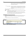
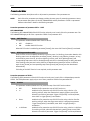
P16x
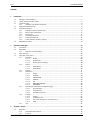
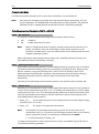
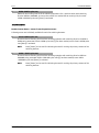
1.5.4
Grounding Instructions
Figure 1-1
P16x/EN M/B
Grounding instructions for P60 Agile
- 13/479 -
Technical Manual
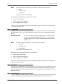
P16x
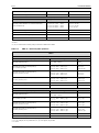
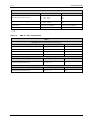
Ground straps of 250mm in length and above are to be used to connect the grounding connection point of
P60 Agile housing to the panel housing. The following table provides information about standard cross
sections and dimensions of ground straps to be applied according to their length.
Table 1-5
Ground straps – Standard cross sections and dimensions
Length (l)
[mm]
Cross section (A)
2
[mm ]
Diameter of wire (d)
[mm]
Dimensions (width x thickness)
2
[mm ]
250 – 500
500 – 750
750 – 1000
6
10
16
0.16
0.16
0.16
9x1
14 x 1.5
20 x 1.6
P16x/EN M/B
- 14/479 -
Technical Manual
P16x
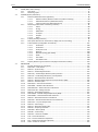
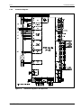
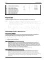
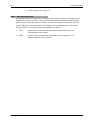
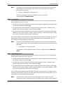
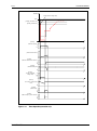
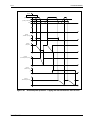
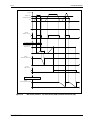
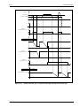
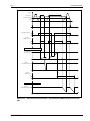
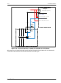
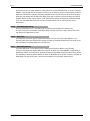
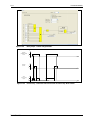
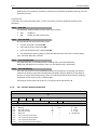
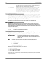
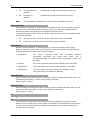
1.5.5
Connection Diagrams
Figure 1-2
P16x/EN M/B
Connection diagram for P60 Agile P163
- 15/479 -
Technical Manual
P16x
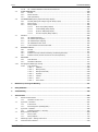
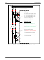
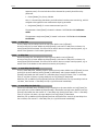
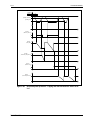
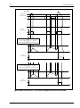
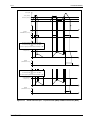
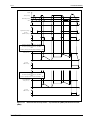
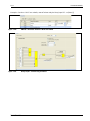
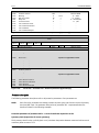
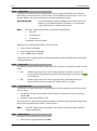
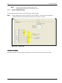
1.5.6
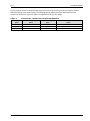
Table 1-6
Communication interfaces (options):
P60 Agile Self supervision – error detection
Figure 1-3 Connection diagram for P60 Agile: Communication interfaces (options)
NOTE: Communication options vary according to the ordering code
P16x/EN M/B
- 16/479 -
Technical Manual
P16x
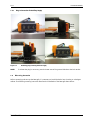
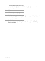
1.5.7
Plug-In Connection for Auxiliary Supply
Press
here
Hold down and push up
Figure 1-4
NOTE:
1.6
Releasing plug-in locking of device supply
To release the plug-in connector, press the lower area of the grooved side where the lock catches.
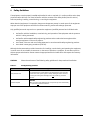
Mounting instruction
Before connecting and start-up the P60 Agile, it is necessary to install the device into a housing or switchgear
cabinet. The following mounting instruction describes the installation of the P60 Agile P16x devices.
P16x/EN M/B
- 17/479 -
Technical Manual
P16x
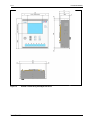
Figure 1-5
P16x/EN M/B
Detailed 3-view-drawing of P60 Agile P16x device
- 18/479 -
Technical Manual
P16x
First, it is necessary to prepare a cut-out in the door panel of the cubicle. The only restriction regarding this is
the size of the existing installation surface. This may not fall below the overall dimensions of the P60 Agile
P16x device.
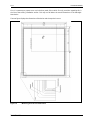
The next figure displays the dimensions of the device and the required cut-out:
Figure 1-6
P16x/EN M/B
Mounting and cut-out dimensions
- 19/479 -
Technical Manual
P16x
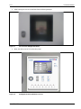
1. After finishing the cut-out it shall look like the following example.
Figure 1-7
Cut-out for the P60 Agile P16x device
2. Now, the device can be fit into the door panel.
Figure 1-8
P16x/EN M/B
P60 Agile P16x device placement in cut-out
- 20/479 -
Technical Manual
P16x
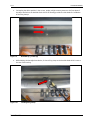
3. For keeping the device position in the cut-out, employ a slight counter-pressure to the front plate of
the device and look to the backside. Each side of the housing provides four bolt heads for installation
of the fixing clamps:
Figure 1-9
Bolt heads (e.g. on the top)
4. While holding the P60 Agile P16x device, click one fixing clamp to the that bolt head which is next to
the rear of the housing:
Figure 1-10
P16x/EN M/B
Installing fixing clamps
- 21/479 -
Technical Manual
P16x
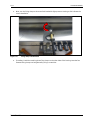
5. Now, turn the fixing clamp to the second bolt head with slight pressure. Hearing a click indicates the
correct installation.
Figure 1-11
Fixing clamp in the bolt head
6. Thereafter, install the remaining three fixing clamps on the other sides of the housing. Now the four
fastened fixing clamps can be tightened by using a screwdriver.
P16x/EN M/B
- 22/479 -
Technical Manual
P16x
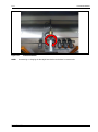
Figure 1-12
NOTE:
Finished installation
Unmounting or changing the P60 Agile P16x device can be done in reverse order.
P16x/EN M/B
- 23/479 -
Technical Manual
P16x
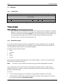
2
Operation of P60 Agile
This section describes the user interface (HMI), which comprises the display elements and the keypads.
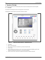
2.1 Front Panel
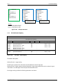
The interface of the P60 Agile consists of a large graphic LCD touchscreen.
Following figure represent the front panel and its elements in detail.
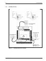
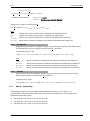
Figure 2-1
Display and operating elements – P60 Agile front panel
1. Front plate
2. Back-lit LCD touchscreen
3. Alarm LEDs for indication of protection trip, alarms and system state
4. Function keys
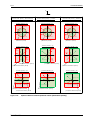
5. Eight configurable LED indications (multi-coloured: green/red/yellow) and labelling area for LEDindications (inserted strip, see Figure 2-2: mm as unit of measure)
6. USB-A communication interface for PC/Notebook (P60 Agile Configurator software)
P16x/EN M/B
- 24/479 -
Technical Manual
P16x
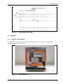
Figure 2-2
2.2
2.2.1
Insertable label strip for LEDs
Back Panel
Reference to documentation
The label See documentation at the back panel of P60 Agile points to the location of an exchangeable,
rechargeable battery within the device.
Figure 2-3
P16x/EN M/B
Overview back panel
- 25/479 -
Technical Manual
P16x
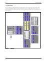
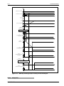
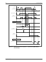
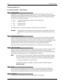
2.3
Menu Structure
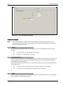
On its LCD-display, the P60 Agile offers several display options. Device settings and controls are also shown.
The user can navigate the Menus using the resistive touchscreen. PC-created graphics, alarms, events, and
measured values can be transferred to the P60. The large graphic display allows the user to view all important
data at a glance.
Figure 2-4
P16x/EN M/B
Menu tree
- 26/479 -
Technical Manual
P16x
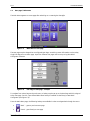
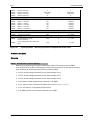
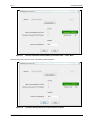
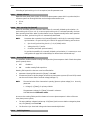
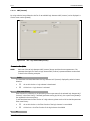
2.4
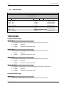
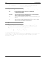
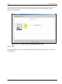
Start page / Main menu
The Main Menu appears as a start page after switching on or resetting the P60 Agile.
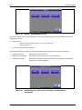
Figure 2-5
Main Menu as start page
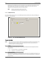
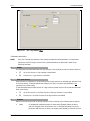
The start page may be changed into a configured User Page, containing custom information such as a bay
single line diagram or an alarm page. Up to four different user pages can be set up using P60 AGILE
Configurator software.
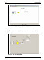
Figure 2-6
User Page as start page – example
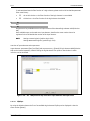
To navigate from a User Page to the main menu, a hotkey may be set up on the User Page which is assigned
to the start page. For this, a pre-defined Main Menu hotkey is available via the library in P60 AGILE
Configurator (see Figure 2-6).
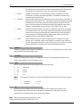
From the Main Menu page, the following hotkeys are available in order to navigate back through the menu:
•
‘Back’ : goes to previous menu page
•
‘Home’: goes directly to start page
P16x/EN M/B
- 27/479 -
Technical Manual
P16x
•
Indications of the lower status line:
Lower display status line: indicates the currently active parameter set
•
Lower display status line: indicates effective ‘Disturbance recorder’
Figure 2-7
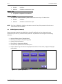
2.4.1
Main menu including navigation hotkeys
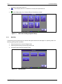
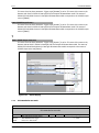
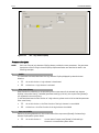
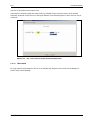
Operating
The Operating menu provides all of the relevant data generated while the P60 Agile is in operating mode. The
following operating data is available:
•
measuring values of current and voltage inputs
•
measuring values during synchronizing process and
•
information about SD card and Debug menu.
Figure 2-8
P16x/EN M/B
Operating data
- 28/479 -
Technical Manual
P16x
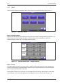
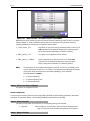
2.4.1.1
Meters
There are several measured value pages which can be used to view measured values in detail, such as:
Figure 2-9
Operating – Meters
Meters \ Voltage/Frequency
Depending on the P60 Agile device variant and according to the number of voltage measuring inputs PT1, PT2
and PT3, phase-to-ground voltages and phase-to-phase voltages will be displayed phase-selectively.
Displayed frequency values refer to the voltage measuring inputs.
Figure 2-10
Operating measurements – Voltage/Frequency
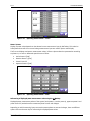
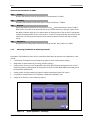
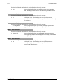
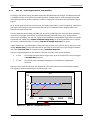
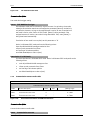
Meters \ Current
This page displays information on current values. In addition to the present measured values, changes from
previous measurements are calculated and the maximum value is saved. Differential currents are displayed
only for devices with differential current input.
The bargraphs indicate the current trends as a percentage of the nominal value. Depending on the set values
of the bargraphs’ colour thresholds (parameters), the bargraphs show the colours green, orange or red.
P16x/EN M/B
- 29/479 -
Technical Manual
P16x
Figure 2-11
Operating measurements – Current
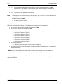
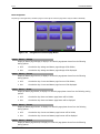
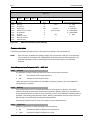
Meters \Power
Display of power values depends on the selected current measurement input by Ref hotkey. This selection
hotkey determines which current and voltage measurement input are used for power value display.
The first row displays total power measurement values; it follows a phase-selective representation according
to phases L1, L2 and L3. Measured quantities are as follows:
•
Active Power P [kW]
•
Reactive Power Q [kvar]
•
Power Factor PF
•
Apparent Power S [kVA]
Figure 2-12
Operating measurements – Power
Referencing of displayed power measurement values using the Ref hotkey:
Displayed power measurement values of the system (active power P, reactive power Q, apparent power S and
power factor PF) are deducted from measured phase currents and voltages.
Depending on which measuring inputs are used to measure phase currents and voltages, there are different
options of the touchscreen key for referencing the displayed power values:
P16x/EN M/B
- 30/479 -
Technical Manual
P16x
•
•
NOTE:
CT1:
CT2:
Displayed power measurement values, based on phase currents measured by CT1 and
measurement of the voltages by that measuring input which is assigned to parameter PT
reference [P9410].
This option is not supported in P16x devices.
The assignment of the voltage measurement input (PT1, PT2 or PT3) to the current measurement
input CT1 should be done using the following parameters, in the submenu
SYSTEM\Measuring\Power:
• PT reference [P9410] for CT1
Sign definition of active power P and reactive power Q
The positive or negative sign indication of the measurement quantities P and Q depends on
•
the connection of the potential transformer (as reference) and
•
the connection of the current transformer and
•
the parameter settings to invert the direction of current measurement per phase in CT1:
o
o
o
o
o
o
•
the setting of parameter:
o
•
Direction L1 (Measuring) [P662]
Direction L2 (Measuring) [P663]
Direction L3 (Measuring) [P664]
Direction L1 (Protection) [P665]
Direction L2 (Protection) [P666]
Direction L3 (Protection) [P667]
Definition [P9411] to define power direction of POWER CT1
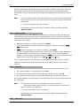
the direction of the primary load flow (while operating normally) in the feeder which is considered for
power measurement.
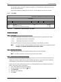
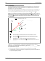
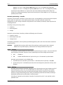
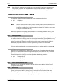
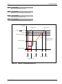
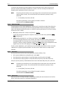
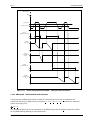
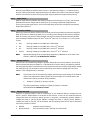
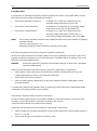
NOTE 1: CT2 is not available in P16x Agile models, therefore power calculations will be based on CT1
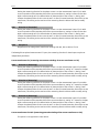
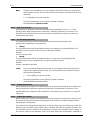
NOTE 2: The above is only valid for a three-phase system with a clockwise field of rotation.
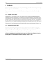
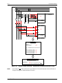
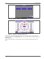
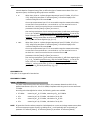
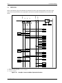
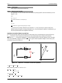
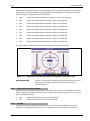
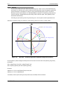
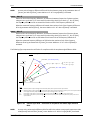
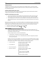
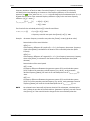
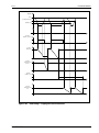
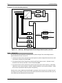
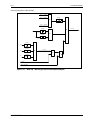
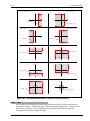
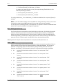
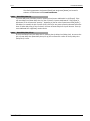
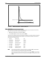
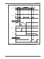
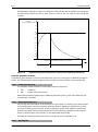
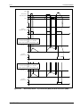
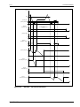
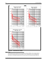
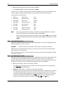
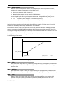
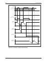
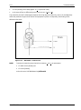
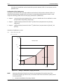
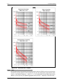
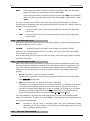
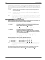
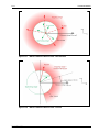
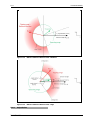
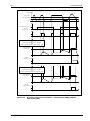
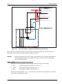
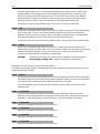
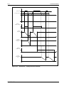
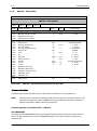
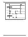
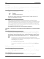
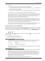
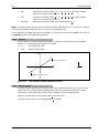
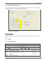
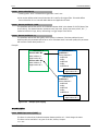
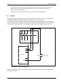
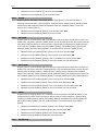
The following diagram shows the sign definition for measurement quantities P and Q according to the above
mentioned conditions:
P16x/EN M/B
- 31/479 -
Technical Manual
P16x
L1
U31
U12
L2
U23
L3
17
U'12 U'31
19
U'23
P60 Agile
PT1
21
U'L1
U'L2 U'L3
26
15
U'GND
I2
I1
P1
16
PT-GND1
I3
I'1
S1
1
I'1
2
P2 S2
P1 S1
I'2
3
I'2
P1 S1
I'3
5
I'3
P2
CT1
4
P2 S2
6
S2
I'GND
7
8
CT-GND1
Parameter settings:
SCPT ⇒ SYSTEM\Nominals\Measuring:
POWER CT1:
„PT reference“ [P9410]
„Definition“ [P9411]
= „PT1“
= „0°“
SCPT ⇒ SYSTEM\Nominals\Current transformers:
CT1:
„Direction L1 (Measuring)“ [P662]
„Direction L2 (Measuring)“ [P663]
„Direction L3 (Measuring)“ [P664]
„Direction L1 (Protection)“ [P665]
„Direction L2 (Protection)“ [P666]
„Direction L3 (Protection)“ [P667]
= „0°“
= „0°“
= „0°“
= „0°“
= „0°“
= „0°“
Signs of measurement values of P and Q:
Device menu ⇒ Main menu\Measuring\Power:
Active power P:
Reactive power Q:
Figure 2-13
NOTE:
„P>0"
„Q>0", if the current recedes the voltage or
„Q<0", if the current leads the voltage
Example of power measuring – Sign definition of measuring quantities P and Q
Any change in one of the conditions for sign definition of the measured power values will lead to a
change in the sign for measured values of P and Q.
P16x/EN M/B
- 32/479 -
Technical Manual
P16x
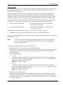
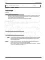
Meters \ Counter
The Counter page provides energy counting values and counting values of operating hours:
Energy counting
For each measuring sample, the values of different power quantities are calculated. At the end of the nominal
period each power value is multiplied by the duration of the nominal period which provides the energy values
for one nominal period. Displayed energy counting values represent summation of all the energy values of one
nominal period individually for all the different energy quantities.
•
•
Absolute/Temporary energy counting values of different power quantities:
o
positive, active power Wp+
o
negative, active power Wp-
o
positive, reactive power Wq+
o
negative, reactive power Wq-
Absolute/Temporary operating hours:
o
h:
hours
o
m:
minutes
o
s:
seconds
Reset
The Reset touch-screen button only refers to temporary counting values (energy values and operating hours).
After reset of temporary counting values counting starts from start value “0”.
Using the reset function it is possible to have counting values for a certain time period without deleting the
counting values for the total operating time.
Figure 2-14
P16x/EN M/B
Operating measurements – Counter
- 33/479 -
Technical Manual
P16x
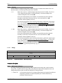
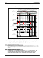
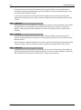
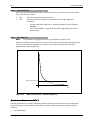
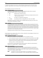
Meters \ Ground
The Meters\Ground page shows all measured or calculated residual voltage and current values.
Figure 2-15
Operating measurements – Ground
Referencing of displayed ground measurement values UG and IG:
According to different manners of building the measurement quantities of the zero sequence system,
following generated measuring values are available:
•
•
•
•
•
•
•
UG,PT1 : residual voltage calculated from the phase voltages of PT1
UG,PT2 : residual voltage calculated from the phase voltages of PT2
UG,PT3 : residual voltage calculated from the phase voltages of PT3
UG,PT-GND1: residual voltage directly measured via PT-GND1
IG,CT1 : ground current calculated from phase currents of CT1 (3 x I0,CT1 = IG,CT1)
IG,CT2: ground current calculated from phase currents of CT2 (3 x I0,CT2 = IGND,CT2)
IG,CT-GND1: ground current directly measured via CT-GND1
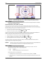
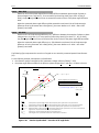
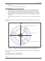
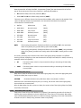
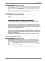
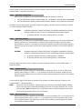
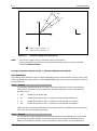
Meters \ U/I Complex
The U/I Complex page shows voltage and/or current measuring values (signals) which can be displayed in
tabulated form or values via vector diagram.
P16x/EN M/B
- 34/479 -
Technical Manual
P16x
Figure 2-16 Selection of display representation
Selection
Up to 6 selectable voltage and current measurement quantities can be displayed via the vector diagram. The
measurement quantities (Signal button) have to be assigned to the vector (Channel button) using the
touchscreen. One additional reference channel (Ref. signal option) is used to define the reference vector (0°)
for the alignment of all other vectors within the diagram.
NOTE:
The measurement quantity (signal) which is assigned to the Ref. signal channel is not
displayed in the vector diagram.
The magnitudes of measuring quantities can be displayed using the Unit ref. button, either as absolute value
(units: [V], [A]), or as relative value ([%]).
Figure 2-17 Operating measurements – Selection of meas. displayed quantities as vectors
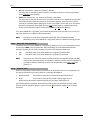
Vector diagram
The colour serves as the corresponding factor between vector and measuring quantity (signal) listed on the
left side of the diagram.
P16x/EN M/B
- 35/479 -
Technical Manual
P16x
Figure 2-18
Operating measurements – selected U/I values via vector diagram
Tabulated form
Each available voltage and current measurement quantity (signal) is displayed according to its magnitude
and phase angle.
Figure 2-19
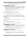
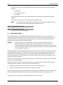
2.4.1.2
Operating measurements – U/I values in tabulated form
Synchronizer
While synchronizing process all relevant measurement values of each synchronizing unit (Sync. unit 1, Sync.
unit 2 or Sync. unit 3) are displayed via the Synchronizer menu page.
P16x/EN M/B
- 36/479 -
Technical Manual
P16x
Figure 2-20
Operating – Selection of synchronizer unit
Figure 2-21
Synchronizer – Manual start of Sync. unit 1
Depending on parameter setting of the synchronizing units, it is possible to perform a manual start of the
synchronizing functions using the Manual Start hotkey. The current synchronization can be cancelled by using
Manual Stop hotkey.
As soon as a synchronizing unit is activated, status information of the selected synchronizing unit will be
shown.
P16x/EN M/B
- 37/479 -
Technical Manual
P16x
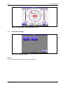
Figure 2-22 Synchronizer – Current state of Sync. unit 1
2.4.1.3
Status (SD Card, Debug)
Figure 2-23
Operating – Status
SD Card
This menu page provides information about the type of SD card.
P16x/EN M/B
- 38/479 -
Technical Manual
P16x
Figure 2-24
Status – SD Card
Debug
This menu page provides information about special data of communication standard IEC 61850.
Figure 2-25
Status – Debug
NOTE: For IEC 61850 communication MAC address is displayed at page 405.
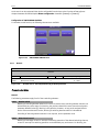
2.4.2
Alarms
The user can find information on active alarm messages as well as all active events on the front panel HMI
display.
2.4.2.1
Active Alarms
When an alarm occurs, this page will open automatically. Depending on the configuration of the alarm
channels, the alarm number (which also serves as event number), the active alarm colour (OFF, red, green or
yellow), and the alarm description (editable text; max. 40 characters) are displayed. Up to 449 alarms can be
managed.
P16x/EN M/B
- 39/479 -
Technical Manual
P16x
Figure 2-26
Active Alarms
Active alarms appear in order of occurrence. If the P60 Agile saves more than 11 alarm messages, the list can
be scrolled up and down via:
•
touch-screen or
•
– if parameterized –assigned buttons on the front panel of the device (see chapter 3.3.6 ‘Graphic’
(Referencing and selection of displayed measurement values)\Button Configuration).
NOTE:
For configuration of the alarms please refer to chapter 3.5.2 ‘Alarm channels’ (configuration via
P60 Configurator Tool only).
If an alarm occurs, the Alarm LED on the front plate and the active alarm colour in the Active alarms menu
page will blink fast until acknowledged or until the alarm is no longer active.
The Alarm LED and the active alarm colour in the Active alarms menu page blinks at a slower interval if the
alarm is no longer active but not yet acknowledged.
An audible signal may also be activated.
Table 2-1 describes LED and audible signal control (beeper) according to the alarm status.
Table 2-1
Alarm status
Alarm status
Alarm is active (upon occurrence)
Alarm is active and acknowledged
Alarm is inactive and not acknowledged
Alarm LED/
active alarm colour
Fast blinking
Permanently ON
Slow blinking
Beeper
Fast interval of sounds
OFF
Slow interval of sounds
If the audible signal is ON, an alarm must be acknowledged twice: once to switch the beeper OFF and a
second time to register the alarm.
Click on the Events key to open the Active Events submenu.
2.4.2.2
Active Events
This page displays all active events by their respective event numbers as well as the total number of active
events. Event registration occurs chronologically with the first column top down.
P16x/EN M/B
- 40/479 -
Technical Manual
P16x
Figure 2-27
Active events
Pressing the Event history hotkey will bring up the list of all stored events.
2.4.3 Breaker
The Breaker selection page gives an overview of the current status of switching elements (circuit breakers,
disconnectors, grounding switches etc.) used in the application.
Figure 2-28
2.4.4
Current breaker status
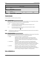
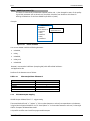
Parameters
The Parameters selection page displays all device settings:
•
SETUP:
Configuration of user levels, and selection of applied current and
voltage measurement inputs
•
SYSTEM:
Nominals, counters, filters, communication and graphic
•
PROTECTION:
Protection settings
P16x/EN M/B
- 41/479 -
Technical Manual
P16x
•
ALARMS:
Parameter number to stop Event History; Alarm numbers
and assigned texts of the Alarm channels, and LED
configuration
•
I/O :
Binary inputs and outputs
•
BREAKER CONTROL:
Feedback signals of switching elements, configuration of
applied switching elements, and counter for switching
operations
•
RECORDER:
Configuration of fault recorder and disturbance recorder
NOTE:
Device parameters cannot be set or modified from the HMI display; they can be set only via the
configuration software P60 Agile Configurator.
Figure 2-29
2.4.4.1
Parameter settings of P60 Agile
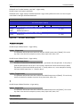
SETUP
The SETUP menu shows how the P60 Agile variant has been adapted to the application. For this, two submenus are provided:
•
User levels sub-menu (configured user access levels) and
•
Measuring Inputs sub-menu (enable /disable menu for the current measurement inputs: CT1 and
CT-GND1, and voltage measurement inputs: PT1, PT2, PT3, PT-GND1)
P16x/EN M/B
- 42/479 -
Technical Manual
P16x
Figure 2-30
SETUP - Adaption of device variant to the application
User levels
The User Levels submenu provides parameters to individually configure the different user levels. Parameters
refer to:
•
the activation of the different user access levels, and
•
the assignment of certain functions to the different user levels.
Measuring inputs
The Measuring inputs submenu provides parameters to enable/disable current and voltage measurement
inputs according to the application.
NOTE:
2.4.4.2
Disabled measurement inputs will not provide any measurement quantities.
SYSTEM
The SYSTEM submenu provides all the system parameters of P60 Agile. Further information on this can be
found in the System Settings chapter.
Figure 2-31
P16x/EN M/B
System parameters
- 43/479 -
Technical Manual
P16x
2.4.4.3
PROTECTION
The PROTECTION submenu provides all the protection parameters of P60 Agile. Further information on this
can be found in Chapter 3.4 PROTECTION.
Figure 2-32
2.4.4.4
Protection parameters
ALARMS
The ALARMS submenu provides all of the parameters relating to alarms and LED configuration of P60 Agile.
Further information on this can be found in the System Settings chapter.
Figure 2-33
2.4.4.5
Alarm parameters
I/O
The I/O submenu provides all the parameters about binary inputs and outputs of P60 Agile. Further
information on this can be found in the System Settings chapter.
P16x/EN M/B
- 44/479 -
Technical Manual
P16x
Figure 2-34
2.4.4.6
Parameters of binary inputs and outputs
BREAKER CONTROL
The BREAKER CONTROL submenu provides all the parameters relating to configuration of switching
elements. Further information on this can be found in the ‘System Settings’ chapter.
Figure 2-35
2.4.4.7
Configuration menu for switching elements
RECORDER
The RECORDER submenu provides all of the parameters for configuration of recording functions such as Fault
recorder and Disturbance recorder. Further information on this can be found in the Recorder chapter.
P16x/EN M/B
- 45/479 -
Technical Manual
P16x
Figure 2-36
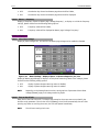
2.4.5
Parameters of recording functions
Recorder (File information and Manual trigger)
P60 Agile device variants provide the following recording functions:
•
Event recorder
•
Fault recorder and
•
Disturbance recorder
Figure 2-37
Recording functions
For each recording function a recording file can be generated. The file endings of the recording files are
assigned as follows:
•
Event recorder:
“xxx.ser“
•
Fault recorder:
“xxx.sfr“
•
Disturbance recorder:
“xxx.sdr“
Read-out data and saving of data recordings
P16x/EN M/B
- 46/479 -
Technical Manual
P16x
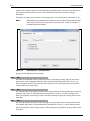
•
It is possible to read the recorded data of the event recorder either via the P60 Agile display or via
PC/Notebook by using the P60 Agile Configurator software; see menu bar Tools\Event recorder, then
click Read Data, then Start.
Clicking File, then Save in the P60 Agile Event recorder window will generate an event recording file
(xxx.ser) including the recorded data. This file can be saved via PC/notebook. This file can only be read
using the P60 Agile Configurator.
•
It is possible to read the recorded data of the fault recorder either via the P60 Agile display or via
PC/Notebook by using the P60 Agile Configurator software; see menu bar Tools\Fault recorder, then
click Read Data, then Start.
Clicking File, then Save in the P60 Agile Fault recorder window will generate a fault recording file
(xxx.sfr) including the recorded data. This file can be saved via PC/notebook. This file can only be read
using the P60 Agile Configurator.
•
It is not possible to read the recorded data of the disturbance recorder via the P60 Agile display.
When disturbance recorder data recording is triggered, either manually or by trigger event, a recording
file (xxx.sdr) is generated on the removable SD Card. This file can be saved by either reading the file
directly from the SD card or by using the P60 Agile Configurator software
NOTE:
2.4.5.1
Saved recording file xxx.sdr cannot be read using P60 Agile Configurator software. However, the
file can be converted to Comtrade format. The Comtrade file can then be opened using appropriate
software.
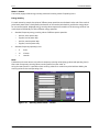
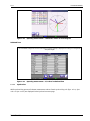
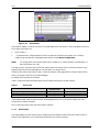
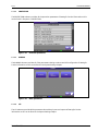
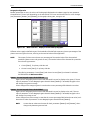
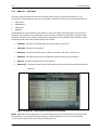
Event Recorder
The event history saves up to 10000 events using the first-in-first-out (FIFO) principle. Each event provides
information such as:
•
the consecutive number
•
the event number
•
the event text
•
date and time stamp
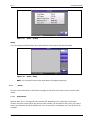
Figure 2-38
NOTE:
Event recorder
In the displayed event list active events are highlighted light green, and inactive events are
represented with white background colour.
P16x/EN M/B
- 47/479 -
Technical Manual
P16x
The latest event is always assigned to number “0”.
Events are recorded with a temporal resolution of 1 ms, and will be displayed in chronological order. The
latest event is at the top of the event list. To scroll the list either use button Up/Down or the scroll bar on the
left of the display.
To refresh the displayed event list automatically, an Auto Refresh button is available on the screen, with the
settings:
•
ON:
will activate automatic refresh.
•
OFF:
will deactivate automatic refresh of the displayed event list.
NOTE:
2.4.5.2
When using the scroll buttons or the scroll bar, the automatic refresh of the event list is stopped
(Auto Refresh: OFF).
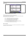
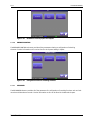
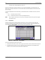
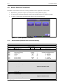
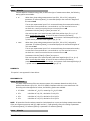
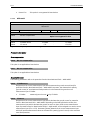
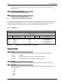
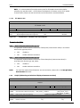
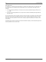
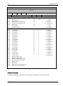
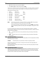
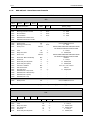
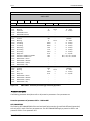
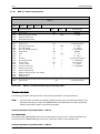
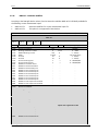
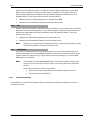
Fault Recorder
The fault recorder saves up to 1000 recordings using the first-in-first-out (FIFO) principle. When fault
recording is started by the active trigger event which is assigned to parameter Trigger event [P8061] (see
menu: RECORDING/Fault recorder), it takes a snapshot of the measurement values.
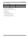
Figure 2-39
Fault recorder – File information
At the time of activating the fault recorder records:
•
all relevant file information (record number, trigger-event number, event text, date and time stamp) and
•
all available measuring values of current, voltage and frequency (depending on the P60 Agile device
variant) for one record,at the time of activating the trigger-event.
P16x/EN M/B
- 48/479 -
Technical Manual
P16x
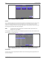
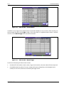
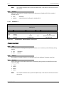
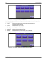
Figure 2-40
Fault recorder – File information
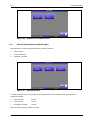
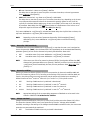
In addition to any trigger event (assigned event to parameter P[8061] or any trip-event), fault recording can
also be started manually via the Trigger hotkey. In this case, there is no registered event-number in the fault
recorder, but the Manual trigger event-text will be indicated.
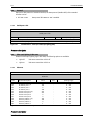
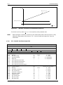
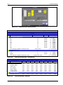
Figure 2-41
Fault recorder – Manual Trigger
At the time of activating the fault recorder records:
•
all relevant file information (record number, trigger-event number, event text, date and time stamp) and
•
all available measuring values of current, voltage and frequency (depending on the P60 Agile device
variant) for one record, at the time of activating the trigger-event:
P16x/EN M/B
- 49/479 -
Technical Manual
P16x
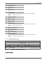
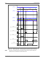
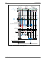
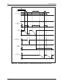
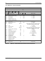
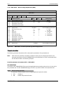
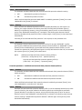
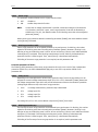
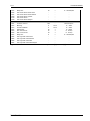
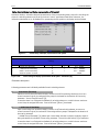
Main menu\Recorder\Fault Recorder
Fault Recorder Level2
Label
Event no.
Event name
Date
Time
Pickup source
Fault phase
Prot. step no.
Prot. set no.
UL1 (PT1)
UL2 (PT1)
UL3 (PT1)
U12 (PT1)
U23 (PT1)
U31 (PT1)
UL1 (PT2)
UL2 (PT2)
UL3 (PT2)
U12 (PT2)
U23 (PT2)
U31 (PT2)
UL1 (PT3)
UL2 (PT3)
UL3 (PT3)
U12 (PT3)
U23 (PT3)
U31 (PT3)
UG (PTGND1)
IL1 (CT1)
IL2 (CT1)
IL3 (CT1)
IL1 (CT2)*
IL2 (CT2)*
IL3 (CT2)*
IG (CT-GND1)
f (PT1)
f (PT2)
f (PT3)
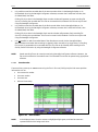
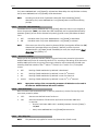
Figure 2-42
NOTE:
Value
Unit
-
0.00
0.00
0.00
0.00
0.00
0.00
0.00
0.00
0.00
0.00
0.00
0.00
0.00
0.00
0.00
0.00
0.00
0.00
0.00
V
V
V
V
V
V
V
V
V
V
V
V
V
V
V
V
V
V
0.00
0.00
0.00
0.00
0.00
0.00
0.00
0.00
0.00
0.00
A
A
A
A
A
A
A
Hz
Hz
Hz
V
Fault recorder – Snapshot of measuring values
The recorded data of each fault recording is saved as an individual fault recording file (“xxx.sfr”)
on the SD card. A read-out of the recording file data is only possible using the P60 Configurator.
The recorded data of a fault recording can be shown on the device display by double-clicking the
selected file entry on the following menu page:
Main Menu\Recorder\Fault Recorder.
* CT2 option not supported in P16x devices.
P16x/EN M/B
- 50/479 -
Technical Manual
P16x
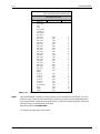
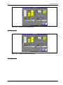
2.4.5.3
Disturbance Recorder
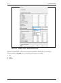
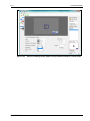
Figure 2-43
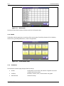
2.4.6
Disturbance recorder – manual trigger
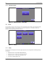
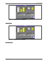
Settings
This page allows changes to device settings of colour and brightness of the display, menu language and time,
displayed single line diagram, entering different user levels (in preparation). All available counters and
memories can be reset through the Resets submenu.
Figure 2-44
2.4.6.1
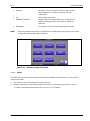
Settings
Display
The colour layout and brightness of the menu page components can be changed with the following settings
on this page:
•
Background colour of menu pages (Page Background)
•
Background colour of Hotkey lower half (Button Bottom)
•
Background colour of Hotkey upper half (Button Top)
•
Text colour of Hotkeys (Button Text )
P16x/EN M/B
- 51/479 -
Technical Manual
P16x
Settings of brightness only refer to the whole menu page. For changing brightness, please use the touchscreen slider control. Colours can be adapted separately by red, green and blue settings. The array Preview
shows the adjusted colour scheme. To save the settings, press button Apply. For resetting the colour scheme
to factory settings, press button Restore Defaults.
Figure 2-45
2.4.6.2
Display Settings
Language & Time
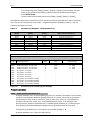
Menu language, date and time can be set under Change Language & Time.
Figure 2-46
2.4.6.3
Change Language & Time
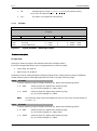
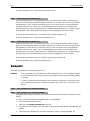
User Level (Change-over via touchscreen)
Changing to different user levels via touchscreen is possible under Change User Level.
P16x/EN M/B
- 52/479 -
Technical Manual
P16x
Figure 2-47 Change User Level
To change User Level, a 4 digit password should be entered via the number keypad on the touchscreen.
Pressing the OK hotkey will automatically open the required user level.
When user level 2, 3 or 4 is activated, a symbol of a key and the number of the active user levels is shown in
the date row.
Figure 2-48
Example: Indication of active user level “2”
The Reset User Level hotkey allows the user to exit from an advanced access level and resets the device to
Level 1 access.
NOTE: There is no symbol for active user level 1
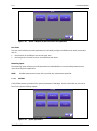
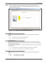
2.4.6.4
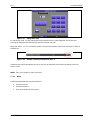
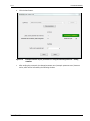
Reset
The Reset page enables the reset (data erase) of
•
the event recorder,
•
the fault recorder or
•
all of the resettable device functions.
P16x/EN M/B
- 53/479 -
Technical Manual
P16x
Figure 2-49
Reset
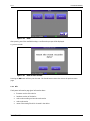
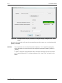
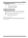
After pressing one of the available hotkeys, a confirmation prompt will be displayed.
e.g. event recorder
Figure 2-50
Reset of event recorder
Pressing the OK button will carry out the reset. The Cancel button returns the user to the previous menu
page.
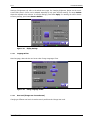
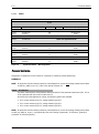
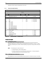
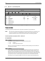
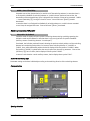
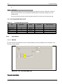
2.4.7 Info
The System Information page gives information about:
•
firmware version of the device
•
hardware version of the device
•
order code according to the order code version
•
order code version
•
name of the setting file which is saved in the device
P16x/EN M/B
- 54/479 -
Technical Manual
P16x
Figure 2-51
P16x/EN M/B
System Information
- 55/479 -
Technical Manual
P16x
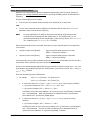
3
System settings
3.1
All Events
3.1.1
Introduction Event System
The event system of P60 Agile allows the user to implement individual applications, as events are used to
activate or deactivate device functions. An event is the internal logic representation of the device process. The
event system offers source and sink events.
The source events have unique and permanent event numbers. A source event will be activated (positive logic:
“true”) if the conditions of this event are met (e.g. threshold exceeded); otherwise it is inactive (positive logic:
“false”).
Sink events are linked to fixed processes or functions and are user-programmable. The user may connect
source and sink by assigning the source number to the sink. The sink (function) will then be active as soon as
the corresponding source gets active.
NOTE:
Some modules are both a source and a sink; for example all binary outputs are sinks and activated
by a source event. But each binary output, however, again generates source events upon its
activation. The same applies for alarm messages and all elements of the programmable logic unit
(PLC). Source events can be linked via logic elements of the PLC and then generate new source
events.
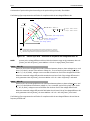
EXAMPLE:
The overcurrent protection ANSI 50/51 is meant to open a breaker via binary output (Shunt
Trip 1). ANSI 50/51 is a source and the binary output a sink. For instance, an event number
referring to ANSI 50/51 is ANSI50/51-1 trip [E1425] (1st limit attained and delay time run
down).
This event number has to be set to one setting (e.g. 01 = 1425) of the binary output Shunt
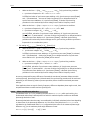
Trip 1 and, as a consequence, protection trip signal opens the breaker.
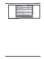
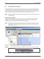
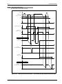
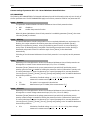
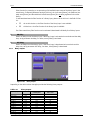
3.1.2
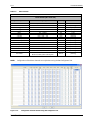
Event list
The event list summarises all software events that are available by the device.
NOTE:
Event numbers (e.g. [E1234]) relating to parameter sets (SET1 – SET4) exist only once for all four
parameter sets.
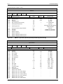
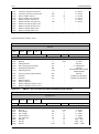
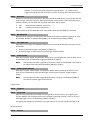
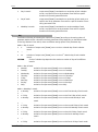
Table 3-1
Event No.
P60 Agile event list
Name
Event
system
Event
recorder
Event is always inactive (untrue)
Event is always active (true)
-
Alarm channel 1 – 449
Alarm groups 450 – 499
Protection parameter set 1 active
Protection parameter set 2 active
Protection parameter set 3 active
Description
Static event
E0000
E9999
OFF-Event
ON-Event
Alarm events 0001 – 0499
E001 – E449
E450 – E499
Alarm
Groups
SET1 – SET4
Protection events E1000 – E3999
E1000
E1001
E1002
P16x/EN M/B
Prot. param. set 1 active
Prot. param. set 2 active
Prot. param. set 3 active
- 56/479 -
Technical Manual
P16x
Event No.
E1003
E1004
E1005
E1006
E1007
E1050
E1051
E1054
E1055
E1056
E1057
E1058
E1059
E1062
E1063
E1064
E1065
E1066
E1067
E1070
E1071
E1072
E1073
E1074
E1075
E1078
E1079
E1080
E1081
E1082
E1083
E1086
E1087
E1088
E1089
E1090
E1091
E1094
E1095
E1096
E1097
E1098
E1099
E1102
E1103
E1104
E1105
E1106
E1107
E1110
E1111
E1112
E1113
E1114
E1115
E1118
E1119
E1120
E1121
E1122
E1123
E1126
E1127
E1128
P16x/EN M/B
Name
Description
Prot. param. set 4 active
Prot. param. set 1 activated manually
Prot. param. set 2 activated manually
Prot. param. set 3 activated manually
Prot. param. set 4 activated manually
ANSI27 module active
ANSI27 blocked module
ANSI27-1 step active
ANSI27-1 blocked step
ANSI27-1 blocked step by min. start voltage
ANSI27-1 blocked step by min. start frequency
ANSI27-1 pickup
ANSI27-1 trip
ANSI27-2 step active
ANSI27-2 blocked step
ANSI27-2 blocked step by min. start voltage
ANSI27-2 blocked step by min. start frequency
ANSI27-2 pickup
ANSI27-2 trip
ANSI27-3 step active
ANSI27-3 blocked step
ANSI27-3 blocked step by min. start voltage
ANSI27-3 blocked step by min. start frequency
ANSI27-3 pickup
ANSI27-3 trip
ANSI27-4 step active
ANSI27-4 blocked step
ANSI27-4 blocked step by min. start voltage
ANSI27-4 blocked step by min. start frequency
ANSI27-4 pickup
ANSI27-4 trip
ANSI27-5 step active
ANSI27-5 blocked step
ANSI27-5 blocked step by min. start voltage
ANSI27-5 blocked step by min. start frequency
ANSI27-5 pickup
ANSI27-5 trip
ANSI27-6 step active
ANSI27-6 blocked step
ANSI27-6 blocked step by min. start voltage
ANSI27-6 blocked step by min. start frequency
ANSI27-6 pickup
ANSI27-6 trip
ANSI27-7 step active
ANSI27-7 blocked step
ANSI27-7 blocked step by min. start voltage
ANSI27-7 blocked step by min. start frequency
ANSI27-7 pickup
ANSI27-7 trip
ANSI27-8 step active
ANSI27-8 blocked step
ANSI27-8 blocked step by min. start voltage
ANSI27-8 blocked step by min. start frequency
ANSI27-8 pickup
ANSI27-8 trip
ANSI27-9 step active
ANSI27-9 blocked step
ANSI27-9 blocked step by min. start voltage
ANSI27-9 blocked step by min. start frequency
ANSI27-9 pickup
ANSI27-9 trip
ANSI27-10 step active
ANSI27-10 blocked step
ANSI27-10 blocked step by min. start voltage
Protection parameter set 4 active
Event
system
Event
recorder
- 57/479 -
Technical Manual
P16x
Event No.
E1129
E1130
E1131
E1134
E1135
E1136
E1137
E1138
E1139
E1142
E1143
E1144
E1145
E1146
E1147
E1151
E1154
E1155
E1156
E1157
E1162
E1163
E1163
E1164
E1170
E1171
E1172
E1173
E1178
E1179
E1180
E1181
E1186
E1187
E1188
E1189
E1194
E1195
E1196
E1197
E1202
E1203
E1204
E1205
E1210
E1211
E1212
E1213
E1218
E1219
E1220
E1221
E1226
E1227
E1228
E1229
E1234
E1235
E1236
E1237
E1242
E1243
E1244
E1245
P16x/EN M/B
Name
ANSI27-10 blocked step by min. start frequency
ANSI27-10 pickup
ANSI27-10 trip
ANSI27-11 step active
ANSI27-11 blocked step
ANSI27-11 blocked step by min. start voltage
ANSI27-11 blocked step by min. start frequency
ANSI27-11 pickup
ANSI27-11 trip
ANSI27-12 step active
ANSI27-12 blocked step
ANSI27-12 blocked step by min. start voltage
ANSI27-12 blocked step by min. start frequency
ANSI27-12 pickup
ANSI27-12 trip
ANSI59 blocked module
ANSI59-1 step active
ANSI59-1 blocked step
ANSI59-1 pickup
ANSI59-1 trip
ANSI59-2 step active
ANSI59-2 blocked step
ANSI59-2 pickup
ANSI59-2 trip
ANSI59-3 step active
ANSI59-3 blocked step
ANSI59-3 pickup
ANSI59-3 trip
ANSI59-4 step active
ANSI59-4 blocked step
ANSI59-4 pickup
ANSI59-4 trip
ANSI59-5 step active
ANSI59-5 blocked step
ANSI59-5 pickup
ANSI59-5 trip
ANSI59-6 step active
ANSI59-6 blocked step
ANSI59-6 pickup
ANSI59-6 trip
ANSI59-7 step active
ANSI59-7 blocked step
ANSI59-7 pickup
ANSI59-7 trip
ANSI59-8 step active
ANSI59-8 blocked step
ANSI59-8 pickup
ANSI59-8 trip
ANSI59-9 step active
ANSI59-9 blocked step
ANSI59-9 pickup
ANSI59-9 trip
ANSI59-10 step active
ANSI59-10 blocked step
ANSI59-10 pickup
ANSI59-10 trip
ANSI59-11 step active
ANSI59-11 blocked step
ANSI59-11 pickup
ANSI59-11 trip
ANSI59-12 step active
ANSI59-12 blocked step
ANSI59-12 pickup
ANSI59-12 trip
Description
Event
system
Event
recorder
- 58/479 -
Technical Manual
P16x
Event No.
E1250
E1251
E1254
E1255
E1256
E1257
E1258
E1262
E1263
E1264
E1265
E1266
E1270
E1271
E1272
E1273
E1274
E1278
E1279
E1280
E1281
E1282
E1286
E1287
E1288
E1289
E1290
E1294
E1295
E1296
E1297
E1298
E1302
E1303
E1304
E1305
E1306
E1310
E1311
E1312
E1313
E1314
E1318
E1319
E1320
E1321
E1322
E1326
E1327
E1328
E1329
E1330
E1334
E1335
E1336
E1337
E1338
E1342
E1343
E1344
E1345
E1346
E1350
E1351
P16x/EN M/B
Name
ANSI81 module active
ANSI81 blocked module
ANSI81-1 step active
ANSI81-1 blocked step
ANSI81-1 blocked step by min. start voltage
ANSI81-1 pickup
ANSI81-1 trip
ANSI81-2 step active
ANSI81-2 blocked step
ANSI81-2 blocked step by min. start voltage
ANSI81-2 pickup
ANSI81-2 trip
ANSI81-3 step active
ANSI81-3 blocked step
ANSI81-3 blocked step by min. start voltage
ANSI81-3 pickup
ANSI81-3 trip
ANSI81-4 step active
ANSI81-4 blocked step
ANSI81-4 blocked step by min. start voltage
ANSI81-4 pickup
ANSI81-4 trip
ANSI81-5 step active
ANSI81-5 blocked step
ANSI81-5 blocked step by min. start voltage
ANSI81-5 pickup
ANSI81-5 trip
ANSI81-6 step active
ANSI81-6 blocked step
ANSI81-6 blocked step by min. start voltage
ANSI81-6 pickup
ANSI81-6 trip
ANSI81-7 step active
ANSI81-7 blocked step
ANSI81-7 blocked step by min. start voltage
ANSI81-7 pickup
ANSI81-7 trip
ANSI81-8 step active
ANSI81-8 blocked step
ANSI81-8 blocked step by min. start voltage
ANSI81-8 pickup
ANSI81-8 trip
ANSI81-9 step active
ANSI81-9 blocked step
ANSI81-9 blocked step by min. start voltage
ANSI81-9 pickup
ANSI81-9 trip
ANSI81-10 step active
ANSI81-10 blocked step
ANSI81-10 blocked step by min. start voltage
ANSI81-10 pickup
ANSI81-10 trip
ANSI81-11 step active
ANSI81-11 blocked step
ANSI81-11 blocked step by min. start voltage
ANSI81-11 pickup
ANSI81-11 trip
ANSI81-12 step active
ANSI81-12 blocked step
ANSI81-12 blocked step by min. start voltage
ANSI81-12 pickup
ANSI81-12 trip
ANSI27T module active
ANSI27T blocked module
Description
Event
system
Event
recorder
- 59/479 -
Technical Manual
P16x
Event No.
E1352
E1353
E1354
E1355
E1356
E1357
E1370
E1371
E1373
E1374
E1375
E1376
E1381
E1382
E1383
E1384
E1389
E1390
E1391
E1392
E1397
E1398
E1399
E1400
E1405
E1406
E1408
E1409
E1410
E1412
E1413
E1415
E1416
E1422
E1423
E1424
E1425
E1430
E1431
E1432
E1433
E1438
E1439
E1440
E1441
E1446
E1447
E1448
E1449
E1454
E1455
E1456
E1457
E1462
E1463
E1464
E1465
E1470
E1471
E1472
E1473
E1474
E1475
E1476
P16x/EN M/B
Name
ANSI27T reactivate limit reached
ANSI27T activate limit reached
ANSI27T pickup
ANSI27T trip
ANSI27T trip by voltage drops count
ANSI27T trip by curve underrun
ANSI59N/G module active
ANSI59N/G blocked module
ANSI59N/G-1 step active
ANSI59N/G-1 blocked step
ANSI59N/G-1 pickup
ANSI59N/G-1 trip
ANSI59N/G-2 step active
ANSI59N/G-2 blocked step
ANSI59N/G-2 pickup
ANSI59N/G-2 trip
ANSI59N/G-3 step active
ANSI59N/G-3 blocked step
ANSI59N/G-3 pickup
ANSI59N/G-3 trip
ANSI59N/G-4 step active
ANSI59N/G-4 blocked step
ANSI59N/G-4 pickup
ANSI59N/G-4 trip
ANSI27Q module active
ANSI27Q blocked module
ANSI27Q pickup
ANSI27Q 1st trip
ANSI27Q 2nd trip
ANSI27Q voltage reclosing limit reached
ANSI27Q reclosing release
ANSI50/51 module active
ANSI50/51 blocked module
ANSI50/51-1 step active
ANSI50/51-1 blocked step
ANSI50/51-1 pickup
ANSI50/51-1 trip
ANSI50/51-2 step active
ANSI50/51-2 blocked step
ANSI50/51-2 pickup
ANSI50/51-2 trip
ANSI50/51-3 step active
ANSI50/51-3 blocked step
ANSI50/51-3 pickup
ANSI50/51-3 trip
ANSI50/51-4 step active
ANSI50/51-4 blocked step
ANSI50/51-4 pickup
ANSI50/51-4 trip
ANSI50/51-5 step active
ANSI50/51-5 blocked step
ANSI50/51-5 pickup
ANSI50/51-5 trip
ANSI50/51-6 step active
ANSI50/51-6 blocked step
ANSI50/51-6 pickup
ANSI50/51-6 trip
ANSI95i-CT1 module active
ANSI95i-CT1 blocked module
ANSI95i-CT1 blocked module by Imax
ANSI95i-CT1 L1 blocked by 2H
ANSI95i-CT1 L2 blocked by 2H
ANSI95i-CT1 L3 blocked by 2H
ANSI95i-CT1 L1 blocked by 5H
Description
Event
system
Event
recorder
- 60/479 -
Technical Manual
P16x
Event No.
E1477
E1478
E1479
E1480
E1515
E1516
E1517
E1518
E1519
E1520
E1521
E1570
E1571
E1576
E1577
E1578
E1579
E1580
E1584
E1585
E1586
E1587
E1588
E1592
E1593
E1594
E1595
E1596
E1600
E1601
E1606
E1607
E1608
E1609
E1610
E1614
E1615
E1616
E1617
E1618
E1622
E1623
E1624
E1625
E1626
E1680
E1681
E1687
E1688
E1689
E1690
E1695
E1696
E1697
E1698
E1703
E1704
E1705
E1706
E1711
E1712
E1713
E1714
E1719
P16x/EN M/B
Name
ANSI95i-CT1 L2 blocked by 5H
ANSI95i-CT1 L3 blocked by 5H
ANSI95i-CT1 2H supervision blocked
ANSI95i-CT1 5H supervision blocked
ANSI95i-GND1 module active
ANSI95i-GND1 blocked module
ANSI95i-GND1 blocked module by Imax
ANSI95i-GND1 blocked by 2H
ANSI95i-GND1 blocked by 5H
ANSI95i-GND1 2H supervision blocked
ANSI95i-GND1 5H supervision blocked
ANSI78 module active
ANSI78 blocked module
ANSI78-1 step active
ANSI78-1 blocked step
ANSI78-1 blocked by min. start voltage
ANSI78-1 pickup
ANSI78-1 trip
ANSI78-2 step active
ANSI78-2 blocked step
ANSI78-2 blocked by min. start voltage
ANSI78-2 pickup
ANSI78-2 trip
ANSI78-3 step active
ANSI78-3 blocked step
ANSI78-3 blocked by min. start voltage
ANSI78-3 pickup
ANSI78-3 trip
ANSI 81R module active
ANSI 81R blocked module
ANSI 81R-1 step active
ANSI 81R-1 blocked step
ANSI 81R-1 blocked by MSV
ANSI 81R-1 pickup
ANSI 81R-1 trip
ANSI 81R-2 step active
ANSI 81R-2 blocked step
ANSI 81R-2 blocked by MSV
ANSI 81R-2 pickup
ANSI 81R-2 trip
ANSI 81R-3 step active
ANSI 81R-3 blocked step
ANSI 81R-3 blocked by MSV
ANSI 81R-3 pickup
ANSI 81R-3 trip
ANSI50G/51G module active
ANSI50G/51G blocked module
ANSI50G/51G-1 step active
ANSI50G/51G-1 blocked step
ANSI50G/51G-1 pickup
ANSI50G/51G-1 trip
ANSI50G/51G-2 step active
ANSI50G/51G-2 blocked step
ANSI50G/51G-2 pickup
ANSI50G/51G-2 trip
ANSI50G/51G-3 step active
ANSI50G/51G-3 blocked step
ANSI50G/51G-3 pickup
ANSI50G/51G-3 trip
ANSI50G/51G-4 step active
ANSI50G/51G-4 blocked step
ANSI50G/51G-4 pickup
ANSI50G/51G-4 trip
ANSI50G/51G-5 step active
Description
Event
system
Event
recorder
- 61/479 -
Technical Manual
P16x
Event No.
E1720
E1721
E1722
E1727
E1728
E1729
E1730
E1735
E1736
E1741
E1742
E1743
E1744
E1745
E1746
E1747
E1748
E1749
E1750
E1751
E1757
E1758
E1759
E1760
E1761
E1762
E1763
E1764
E1765
E1766
E1767
E1773
E1774
E1775
E1776
E1777
E1778
E1779
E1780
E1781
E1782
E1783
E1789
E1790
E1791
E1792
E1793
E1794
E1795
E1796
E1797
E1798
E1799
E1805
E1806
E1807
E1808
E1809
E1810
E1815
E1816
E1817
E1818
E1823
P16x/EN M/B
Name
ANSI50G/51G-5 blocked step
ANSI50G/51G-5 pickup
ANSI50G/51G-5 trip
ANSI50G/51G-6 step active
ANSI50G/51G-6 blocked step
ANSI50G/51G-6 pickup
ANSI50G/51G-6 trip
ANSI67 module active
ANSI67 blocked module
ANSI67-1 step active
ANSI67-1 blocked step
ANSI67-1 pickup L1
ANSI67-1 pickup L2
ANSI67-1 pickup L3
ANSI67-1 pickup
ANSI67-1 trip L1
ANSI67-1 trip L2
ANSI67-1 trip L3
ANSI67-1 trip
ANSI67-1 low voltage
ANSI67-2 step active
ANSI67-2 blocked step
ANSI67-2 pickup L1
ANSI67-2 pickup L2
ANSI67-2 pickup L3
ANSI67-2 pickup
ANSI67-2 trip L1
ANSI67-2 trip L2
ANSI67-2 trip L3
ANSI67-2 trip
ANSI67-2 low voltage
ANSI67-3 step active
ANSI67-3 blocked step
ANSI67-3 pickup L1
ANSI67-3 pickup L2
ANSI67-3 pickup L3
ANSI67-3 pickup
ANSI67-3 trip L1
ANSI67-3 trip L2
ANSI67-3 trip L3
ANSI67-3 trip
ANSI67-3 low voltage
ANSI67-4 step active
ANSI67-4 blocked step
ANSI67-4 pickup L1
ANSI67-4 pickup L2
ANSI67-4 pickup L3
ANSI67-4 pickup
ANSI67-4 trip L1
ANSI67-4 trip L2
ANSI67-4 trip L3
ANSI67-4 trip
ANSI67-4 low voltage
ANSI32 module active
ANSI32 blocked module
ANSI32-1 step active
ANSI32-1 blocked step
ANSI32-1 pickup
ANSI32-1 trip
ANSI32-2 step active
ANSI32-2 blocked step
ANSI32-2 pickup
ANSI32-2 trip
ANSI32-3 step active
Description
Event
system
Event
recorder
- 62/479 -
Technical Manual
P16x
Event No.
E1824
E1825
E1826
E1831
E1832
E1833
E1834
E1839
E1840
E1841
E1842
E1847
E1848
E1849
E1850
E1855
E1856
E1857
E1858
E1865
E1866
E1867
E1868
E1869
E1870
E1871
E1872
E1873
E1874
E1875
E1876
E1877
E1878
E1879
E1880
E1881
E1882
E1883
E1884
E1885
E1886
E1890
E1891
E1892
E1893
E1894
E1895
E1896
E1897
E1898
E1899
E1900
E1901
E1902
E1903
E1904
E1905
E1906
E2020
E2021
E2022
E2013
E1910
E1911
P16x/EN M/B
Name
ANSI32-3 blocked step
ANSI32-3 pickup
ANSI32-3 trip
ANSI32-4 step active
ANSI32-4 blocked step
ANSI32-4 pickup
ANSI32-4 trip
ANSI32-5 step active
ANSI32-5 blocked step
ANSI32-5 pickup
ANSI32-5 trip
ANSI32-6 step active
ANSI32-6 blocked step
ANSI32-6 pickup
ANSI32-6 trip
ANSI25-1 Active
ANSI25-1 Blocked
ANSI25-1 Negative phase seq. PT1
ANSI25-1 Negative phase seq. PT2
ANSI25-1 SC: Blocked
ANSI25-1 SC: PT1 > Max. voltage
ANSI25-1 SC: PT1 < Min. voltage
ANSI25-1 SC: PT1 > Max. frequency
ANSI25-1 SC: PT1 < Min. frequency
ANSI25-1 SC: PT1 in range
ANSI 25-1 SC: PT2 > Max. voltage
ANSI 25-1 SC: PT2 < Min. voltage
ANSI25-1 SC: PT2 > Max. frequency
ANSI25-1 SC: PT2 < Min. frequency
ANSI25-1 SC: PT2 in range
ANSI25-1 SC: dU > Max. dU
ANSI25-1 SC: dU < Min. dU
ANSI25-1 SC: dU in range
ANSI25-1 SC: df < Min. df
ANSI25-1 SC: df > Max. df
ANSI25-1 SC: df in range
ANSI25-1 SC: dPHI < Min. dPHI
ANSI25-1 SC: dPHI > Max. dPHI
ANSI25-1 SC: dPHI in range
ANSI25-1 SC: Synchronous pre-event
ANSI25-1 SC: Synchronous
ANSI25-1 VC: Blocked
ANSI25-1 VC: PT1 > Max. voltage
ANSI25-1 VC: PT1 < Min. voltage
ANSI25-1 VC: PT1 > Max. frequency
ANSI25-1 VC: PT1 < Min. frequency
ANSI25-1 VC: PT1 in range
ANSI25-1 VC: PT1 > No voltage limit
ANSI25-1 VC: PT1 < No voltage limit
ANSI25-1 VC: PT2 > Max. voltage
ANSI25-1 VC: PT2 < Min. voltage
ANSI25-1 VC: PT2 > Max. frequency
ANSI25-1 VC: PT2 < Min. frequency
ANSI25-1 VC: PT2 in range
ANSI25-1 VC: PT2 > No voltage limit
ANSI25-1 VC: PT2 < No voltage limit
ANSI25-1 VC: Synchronous pre-event
ANSI25-1 VC: Synchronous
ANSI25-1 Frequency higher event
ANSI25-1 Frequency lower event
ANSI25-1 Voltage higher event
ANSI25-1 Voltage lower event
ANSI25-2 Active
ANSI25-2 Blocked
Description
Event
system
Event
recorder
- 63/479 -
Technical Manual
P16x
Event No.
E1912
E1913
E1920
E1921
E1922
E1923
E1924
E1925
E1926
E1927
E1928
E1929
E1930
E1931
E1932
E1933
E1934
E1935
E1936
E1937
E1938
E1939
E1940
E1941
E1945
E1946
E1947
E1948
E1949
E1950
E1951
E1952
E1953
E1954
E1955
E1956
E1957
E1958
E1959
E1960
E1961
E2025
E2026
E2027
E2018
E1965
E1966
E1967
E1968
E1975
E1976
E1977
E1978
E1979
E1980
E1981
E1982
E1983
E1984
E1985
E1986
E1987
E1988
E1989
P16x/EN M/B
Name
ANSI25-2 Negative phase seq. PT1
ANSI25-2 Negative phase seq. PT3
ANSI25-2 SC: Blocked
ANSI25-2 SC: PT1 > Max. voltage
ANSI25-2 SC: PT1 < Min. voltage
ANSI25-2 SC: PT1 > Max. frequency
ANSI25-2 SC: PT1 < Min. frequency
ANSI25-2 SC: PT1 in range
ANSI25-2 SC: PT3 > Max. voltage
ANSI25-2 SC: PT3 < Min. voltage
ANSI25-2 SC: PT3 > Max. frequency
ANSI25-2 SC: PT3 < Min. frequency
ANSI25-2 SC: PT3 in range
ANSI25-2 SC: dU > Max. dU
ANSI25-2 SC: dU < Min. dU
ANSI25-2 SC: dU in range
ANSI25-2 SC: df > Max. df
ANSI25-2 SC: df < Min. df
ANSI25-2 SC: df in range
ANSI25-2 SC: dPHI > Max. dPHI
ANSI25-2 SC: dPHI < Min. dPHI
ANSI25-2 SC: dPHI in range
ANSI25-2 SC: Synchronous pre-event
ANSI25-2 SC: Synchronous
ANSI25-2 VC: Blocked
ANSI25-2 VC: PT1 > Max. voltage
ANSI25-2 VC: PT1 < Min. voltage
ANSI25-2 VC: PT1 > Max. frequency
ANSI25-2 VC: PT1 < Min. frequency
ANSI25-2 VC: PT1 in range
ANSI25-2 VC: PT1 > No voltage limit
ANSI25-2 VC: PT1 < No voltage limit
ANSI25-2 VC: PT3 > Max. voltage
ANSI25-2 VC: PT3 < Min. voltage
ANSI25-2 VC: PT3 > Max. frequency
ANSI25-2 VC: PT3 < Min. frequency
ANSI25-2 VC: PT3 in range
ANSI25-2 VC: PT3 > No voltage limit
ANSI25-2 VC: PT3 < No voltage limit
ANSI25-2 VC: Synchronous pre-event
ANSI25-2 VC: Synchronous
ANSI25-2 Frequency higher event
ANSI25-2 Frequency lower event
ANSI25-2 Voltage higher event
ANSI25-2 Voltage lower event
ANSI25-3 Active
ANSI25-3 Blocked
ANSI25-3 Negative phase seq. PT2
ANSI25-3 Negative phase seq. PT3
ANSI25-3 SC: Blocked
ANSI25-3 SC: PT2 > Max. voltage
ANSI25-3 SC: PT2 < Min. voltage
ANSI25-3 SC: PT2 > Max. frequency
ANSI25-3 SC: PT2 < Min. frequency
ANSI25-3 SC: PT2 in range
ANSI25-3 SC: PT3 > Max. voltage
ANSI25-3 SC: PT3 < Min. voltage
ANSI25-3 SC: PT3 > Max. frequency
ANSI25-3 SC: PT3 < Min. frequency
ANSI25-3 SC: PT3 in range
ANSI25-3 SC: dU > Max. dU
ANSI25-3 SC: dU < Min. dU
ANSI25-3 SC: dU in range
ANSI25-3 SC: df > Max. df
Description
Event
system
Event
recorder
- 64/479 -
Technical Manual
P16x
Event No.
E1990
E1991
E1992
E1993
E1994
E1995
E1996
E2000
E2001
E2002
E2003
E2004
E2005
E2006
E2007
E2008
E2009
E2010
E2011
E2012
E2013
E2014
E2015
E2016
E2030
E2031
E2032
E2033
E2035
E2036
E2038
E2039
E2040
E2041
E2042
E2046
E2047
E2048
E2049
E2050
E2054
E2055
E2056
E2057
E2058
E2062
E2063
E2064
E2065
E2066
E2070
E2071
E2072
E2073
E2076
E2077
E2078
E2079
E2080
E2084
E2085
E2086
E2087
E2090
P16x/EN M/B
Name
ANSI25-3 SC: df < Min. df
ANSI25-3 SC: df in range
ANSI25-3 SC: dPHI > Max. dPHI
ANSI25-3 SC: dPHI < Min. dPHI
ANSI25-3 SC: dPHI in range
ANSI25-3 SC: Synchronous pre-event
ANSI25-3 SC: Synchronous
ANSI25-3 VC: Blocked
ANSI25-3 VC: PT2 > Max. voltage
ANSI25-3 VC: PT2 < Min. voltage
ANSI25-3 VC: PT2 > Max. frequency
ANSI25-3 VC: PT2 < Min. frequency
ANSI25-3 VC: PT2 in range
ANSI25-3 VC: PT2 > No voltage limit
ANSI25-3 VC: PT2 < No voltage limit
ANSI25-3 VC: PT3 > Max. voltage
ANSI25-3 VC: PT3 < Min. voltage
ANSI25-3 VC: PT3 > Max. frequency
ANSI25-3 VC: PT3 < Min. frequency
ANSI25-3 VC: PT3 in range
ANSI25-3 VC: PT3 > No voltage limit
ANSI25-3 VC: PT3 < No voltage limit
ANSI25-3 VC: Synchronous pre-event
ANSI25-3 VC: Synchronous
ANSI25-3 Frequency higher event
ANSI25-3 Frequency lower event
ANSI25-3 Voltage higher event
ANSI25-3 Voltage lower event
ANSI67G module active
ANSI67G blocked module
ANSI67G-1 step active
ANSI67G-1 blocked step
ANSI67G-1 pickup
ANSI67G-1 trip
ANSI67G-1 low voltage
ANSI67G-2 step active
ANSI67G-2 blocked step
ANSI67G-2 pickup
ANSI67G-2 trip
ANSI67G-2 low voltage
ANSI67G-3 step active
ANSI67G-3 blocked step
ANSI67G-3 pickup
ANSI67G-3 trip
ANSI67G-3 low voltage
ANSI67G-4 step active
ANSI67G-4 blocked step
ANSI67G-4 pickup
ANSI67G-4 trip
ANSI67G-4 low voltage
PTS-1 symmetry check active
PTS-1 symmetry check blocked
PTS-1 symmetry failure
PTS-1 symmetry failure delayed
PTS-1 fuse failure check active
PTS-1 fuse failure check blocked
PTS-1 fuse failure 3 phase
PTS-1 fuse failure failure
PTS-1 fuse failure failure delayed
PTS-1 general check active
PTS-1 general check blocked
PTS-1 general failure
PTS-1 general failure delayed
PTS-2 symmetry check active
Description
Event
system
Event
recorder
- 65/479 -
Technical Manual
P16x
Event No.
E2091
E2092
E2093
E2096
E2097
E2098
E2099
E2100
E2104
E2105
E2106
E2107
E2110
E2111
E2112
E2113
E2116
E2117
E2118
E2119
E2120
E2124
E2125
E2126
E2127
E2130
E2131
E2132
E2133
E2135
E2136
E2137
E2138
E2335
E2336
E2338
E2339
E2340
E2341
E2342
E2344
E2345
E2346
E2347
E2348
E2160
E2161
E2162
E2163
E2164
E2165
E2166
E2167
E2168
E2169
E2170
E2171
E2172
E2173
E2174
E2175
E2176
E2180
E2181
P16x/EN M/B
Name
PTS-2 symmetry check blocked
PTS-2 symmetry failure
PTS-2 symmetry failure delayed
PTS-2 fuse failure check active
PTS-2 fuse failure check blocked
PTS-2 fuse failure 3 phase
PTS-2 fuse failure failure
PTS-2 fuse failure failure delayed
PTS-2 general check active
PTS-2 general check blocked
PTS-2 general failure
PTS-2 general failure delayed
PTS-3 symmetry check active
PTS-3 symmetry check blocked
PTS-3 symmetry failure
PTS-3 symmetry failure delayed
PTS-3 fuse failure check active
PTS-3 fuse failure check blocked
PTS-3 fuse failure 3 phase
PTS-3 fuse failure failure
PTS-3 fuse failure failure delayed
PTS-3 general check active
PTS-3 general check blocked
PTS-3 general failure
PTS-3 general failure delayed
CTS-1 symmetry check active
CTS-1 symmetry check blocked
CTS-1 symmetry fault
CTS-1 symmetry fault delayed
CTS-1 diff check active
CTS-1 diff check blocked
CTS-1 diff fault
CTS-1 diff fault delayed
SOTF active
SOTF blocked
SOTF-1 active
SOTF-1 blocked
SOTF-1 trigger
SOTF-1 pickup
SOTF-1 trip
SOTF-2 active
SOTF-2 blocked
SOTF-2 trigger
SOTF.2 pickup
SOTF-2 trip
ANSI79 Ready
ANSI79 Blocked
ANSI79 Locked
ANSI79 Cycle
ANSI79 1. Pause time
ANSI79 2. Pause time
ANSI79 3. Pause time
ANSI79 4. Pause time
ANSI79 5. Pause time
ANSI79 6. Pause time
ANSI79 7. Pause time
ANSI79 8. Pause time
ANSI79 Breaker close command
ANSI79 Breaker close success time
ANSI79 Success
ANSI79 Fail
ANSI79 Off-time
YG active
YG blocked
Description
Event
system
Event
recorder
- 66/479 -
Technical Manual
P16x
Event No.
E2185
E2186
E2187
E2188
E2190
E2191
E2192
E2193
E2195
E2196
E2197
E2198
E2200
E2201
E2202
E2203
E2205
E2206
E2207
E2208
E2210
E2211
E2212
E2213
E2215
E2216
E2217
E2218
E2219
E2220
E2223
E2224
E2225
E2226
E2229
E2230
E2231
E2232
E2235
E2236
E2237
E2238
E2240
E2241
E2242
E2245
E2246
E2248
E2249
E2250
E2251
E2256
E2257
E2258
E2259
E2264
E2265
E2266
E2267
E2272
E2273
E2274
E2275
E2280
P16x/EN M/B
Name
YG-1 active
YG-1 blocked
YG-1 pickup
YG-1 trip
YG-2 active
YG-2 blocked
YG-2 pickup
YG-2 trip
YG-3 active
YG-3 blocked
YG-3 pickup
YG-3 trip
YG-4 active
YG-4 blocked
YG-4 pickup
YG-4 trip
YG-5 active
YG-5 blocked
YG-5 pickup
YG-5 trip
YG-6 active
YG-6 blocked
YG-6 pickup
YG-6 trip
ANSI50BF module active
ANSI50BF blocked module
ANSI50BF-1 step active
ANSI50BF-1 blocked step
ANSI50BF-1 pickup
ANSI50BF-1 trip
ANSI50BF-2 step active
ANSI50BF-2 blocked step
ANSI50BF-2 pickup
ANSI50BF-2 trip
ANSI50BF-3 step active
ANSI50BF-3 blocked step
ANSI50BF-3 pickup
ANSI50BF-3 trip
ANSI74TC active
ANSI74TC blocked
ANSI74TC pickup
ANSI74TC trip
ANSI51/46VR module active
ANSI51/46VR blocked module
ANSI51/46VR prot.blocking
ANSI46 module active
ANSI46 blocked module
ANSI46-1 step active
ANSI46-1 blocked step
ANSI46-1 pickup
ANSI46-1 trip
ANSI46-2 step active
ANSI46-2 blocked step
ANSI46-2 pickup
ANSI46-2 trip
ANSI46-3 step active
ANSI46-3 blocked step
ANSI46-3 pickup
ANSI46-3 trip
ANSI46-4 step active
ANSI46-4 blocked step
ANSI46-4 pickup
ANSI46-4 trip
ANSI32N/G module active
Description
Event
system
Event
recorder
- 67/479 -
Technical Manual
P16x
Event No.
E2281
E2282
E2283
E2284
E2285
E2290
E2291
E2292
E2293
E2298
E2299
E2300
E2301
E2306
E2307
E2308
E2309
E2314
E2315
E2316
E2317
E2322
E2323
E2324
E2325
E2330
E2331
E2332
E2333
E2350
E2351
E2352
E2353
E2354
E2355
E2356
E2357
E2358
E2359
E2360
E2361
E2362
E2363
E2364
E2365
E2366
E2367
E2368
E2370
E2371
E2372
E2374
E2375
E2376
E2379
E2380
E2381
E2382
E2385
E2386
E2387
Name
Description
ANSI32N/G blocked module
ANSI32N/G-1 step active
ANSI32N/G-1 blocked step
ANSI32N/G-1 pickup
ANSI32N/G-1 trip
ANSI32N/G-2 step active
ANSI32N/G-2 blocked step
ANSI32N/G-2 pickup
ANSI32N/G-2 trip
ANSI32N/G-3 step active
ANSI32N/G-3 blocked step
ANSI32N/G-3 pickup
ANSI32N/G-3 trip
ANSI32N/G-4 step active
ANSI32N/G-4 blocked step
ANSI32N/G-4 pickup
ANSI32N/G-4 trip
ANSI32N/G-5 step active
ANSI32N/G-5 blocked step
ANSI32N/G-5 pickup
ANSI32N/G-5 trip
ANSI32N/G-6 step active
ANSI32N/G-6 blocked step
ANSI32N/G-6 pickup
ANSI32N/G-6 trip
CLD active
CLD blocked
CLD pickup
CLD cold load
ANSI49 module active
ANSI49 module blocked
ANSI49-1 step active
ANSI49-1 step blocked
ANSI49-1 warning
ANSI49-1 trip
ANSI49-2 step active
ANSI49-2 step blocked
ANSI49-2 warning
ANSI49-2 trip
ANSI49-3 step active
ANSI49-3 step blocked
ANSI49-3 warning
ANSI49-3 trip
ANSI49-4 step active
ANSI49-4 step blocked
ANSI49-4 warning
ANSI49-4 trip
ANSI86 module active
ANSI64REF active
ANSI64REF blocked
ANSI64REF-1 active
ANSI64REF-1 blocked
ANSI64REF-1 pickup
ANSI64REF-1 trip
ANSI64REF-2 active
ANSI64REF-2 blocked
ANSI64REF-2 pickup
ANSI64REF-2 trip
ANSI21FL active
ANSI21FL blocked
ANSI21FL busy
Event
system
Event
recorder
Binary input events E4000 – E4499
E4010
P16x/EN M/B
Binary input “Fct. 10 In” input event
Binary input event input event
- 68/479 -
Technical Manual
P16x
Event No.
E4011
E4012
E4013
E4014
E4015
E4016
E4017
E4018
E4019
E4020
E4021
E4022
E4023
E4024
E4025
E4026
E4027
E4028
E4110
E4111
E4112
E4113
E4114
E4115
E4116
E4117
E4118
E4119
E4120
E4121
E4122
E4123
E4124
E4125
E4126
E4127
E4128
E4210
E4211
E4212
E4213
E4214
E4215
E4216
E4217
E4218
E4219
E4220
E4221
E4222
E4223
E4224
E4225
E4226
E4227
E4228
Event
system
Event
recorder
Binary input event input event
Binary input event input event
Binary input event input event
Binary input event input event
Binary input event input event
Binary input event input event
Binary input event input event
Binary input event input event
Binary input event input event
Binary input event input event
Binary input event input event
Binary input event input event
Binary input event input event
Binary input event input event
Binary input event input event
Binary input event input event
Binary input event input event
Binary input event input event
Binary input event predelay event
Binary input event predelay event
Binary input event predelay event
Binary input event predelay event
Binary input event predelay event
Binary input event predelay event
Binary input event predelay event
Binary input event predelay event
Binary input event predelay event
Binary input event predelay event
Binary input event predelay event
Binary input event predelay event
Binary input event predelay event
Binary input event predelay event
Binary input event predelay event
Binary input event predelay event
Binary input event predelay event
Binary input event predelay event
Binary input event predelay event
Binary input event inverted event
Binary input event inverted event
Binary input event inverted event
Binary input event inverted event
Binary input event inverted event
Binary input event inverted event
Binary input event inverted event
Binary input event inverted event
Binary input event inverted event
Binary input event inverted event
Binary input event inverted event
Binary input event inverted event
Binary input event inverted event
Binary input event inverted event
Binary input event inverted event
Binary input event inverted event
Binary input event inverted event
Binary input event inverted event
Binary input event inverted event
Shunt Trip 1 output event
Shunt Trip 2 output event
Lockout relay event
Lockout relay predelay event
Synchron relay event
Synchron relay predelay event
Function output 1event
Name
Description
Binary input “Fct. 11 In” input event
Binary input “Fct. 12 In” input event
Binary input “Fct. 13 In” input event
Binary input “Fct. 14 In” input event
Binary input “Fct. 15 In” input event
Binary input “Fct. 16 In” input event
Binary input “Fct. 17 In” input event
Binary input “Fct. 18 In” input event
Binary input “Fct. 19 In” input event
Binary input “Fct. 20 In” input event
Binary input “Fct. 21 In” input event
Binary input “Fct. 22 In” input event
Binary input “Fct. 23 In” input event
Binary input “Fct. 24 In” input event
Binary input “Fct. 25 In” input event
Binary input “Fct. 26 In” input event
Binary input “Fct. 27 In” input event
Binary input “Fct. 28 In” input event
Binary input “Fct. 10 In” predelay event
Binary input “Fct. 11 In” predelay event
Binary input “Fct. 12 In” predelay event
Binary input “Fct. 13 In” predelay event
Binary input “Fct. 14 In” predelay event
Binary input “Fct. 15 In” predelay event
Binary input “Fct. 16 In” predelay event
Binary input “Fct. 17 In” predelay event
Binary input “Fct. 18 In” predelay event
Binary input “Fct. 19 In” predelay event
Binary input “Fct. 20 In” predelay event
Binary input “Fct. 21 In” predelay event
Binary input “Fct. 22 In” predelay event
Binary input “Fct. 23 In” predelay event
Binary input “Fct. 24 In” predelay event
Binary input “Fct. 25 In” predelay event
Binary input “Fct. 26 In” predelay event
Binary input “Fct. 27 In” predelay event
Binary input “Fct. 28 In” predelay event
Binary input “Fct. 10 In” inverted event
Binary input “Fct. 11 In” inverted event
Binary input “Fct. 12 In” inverted event
Binary input “Fct. 13 In” inverted event
Binary input “Fct. 14 In” inverted event
Binary input “Fct. 15 In” inverted event
Binary input “Fct. 16 In” inverted event
Binary input “Fct. 17 In” inverted event
Binary input “Fct. 18 In” inverted event
Binary input “Fct. 19 In” inverted event
Binary input “Fct. 20 In” inverted event
Binary input “Fct. 21 In” inverted event
Binary input “Fct. 22 In” inverted event
Binary input “Fct. 23 In” inverted event
Binary input “Fct. 24 In” inverted event
Binary input “Fct. 25 In” inverted event
Binary input “Fct. 26 In” inverted event
Binary input “Fct. 27 In” inverted event
Binary input “Fct. 28 In” inverted event
Binary output events E4500 – E4599
E4500
E4501
E4502
E4503
E4504
E4505
E4506
P16x/EN M/B
Shunt Trip 1
Shunt Trip 2
Lockout relay
Lockout relay predelay
Synchron relay
Synchron relay predelay
Function output 1
- 69/479 -
Technical Manual
P16x
Event No.
E4507
E4508
E4509
E4510
E4511
E4512
E4513
E4514
E4515
E4516
E4517
E4518
E4519
E4520
E4521
Event
system
Event
recorder
Function output 1 predelay event
Function output 2 event
Function output 2 predelay event
Function output 3 event
Function output 3 predelay event
Function output 4 event
Function output 4 predelay event
Function output 5 event
Function output 5 predelay event
Function output 6 event
Function output 6 predelay event
Function output 7 event
Function output 7 predelay event
Function output 8 event
Function output 8 predelay event
Event recording stop is active
Breaker 1 (feedback)
Breaker 1 (feedback)
Breaker 1 (feedback)
Breaker 1 (feedback)
Breaker 1 (feedback)
Breaker 1 (feedback)
Breaker 2 (feedback)
Breaker 2 (feedback)
Breaker 2 (feedback)
Breaker 2 (feedback)
Breaker 2 (feedback)
Breaker 2 (feedback)
Breaker 3 (feedback)
Breaker 3 (feedback)
Breaker 3 (feedback)
Breaker 3 (feedback)
Breaker 3 (feedback)
Breaker 3 (feedback)
Breaker 4 (feedback)
Breaker 4 (feedback)
Breaker 4 (feedback)
Breaker 4 (feedback)
Breaker 4 (feedback)
Breaker 4 (feedback)
Breaker 5 (feedback)
Breaker 5 (feedback)
Breaker 5 (feedback)
Breaker 5 (feedback)
Breaker 5 (feedback)
Breaker 5 (feedback)
Breaker 6 (feedback)
Breaker 6 (feedback)
Breaker 6 (feedback)
Breaker 6 (feedback)
Breaker 6 (feedback)
Breaker 6 (feedback)
Breaker 7 (feedback)
Breaker 7 (feedback)
Breaker 7 (feedback)
Breaker 7 (feedback)
Breaker 7 (feedback)
Breaker 7 (feedback)
Breaker 8 (feedback)
Breaker 8 (feedback)
Breaker 8 (feedback)
Name
Description
Function output predelay
Function output 2
Function output predelay
Function output 3
Function output predelay
Function output 4
Function output predelay
Function output 5
Function output predelay
Function output 6
Function output predelay
Function output 7
Function output predelay
Function output 8
Function output predelay
Event system
E5950
Event history stop
Breaker feedback events E6010 – E6085
E6010
E6011
E6012
E6013
E6014
E6015
E6020
E6021
E6022
E6023
E6024
E6025
E6030
E6031
E6032
E6033
E6034
E6035
E6040
E6041
E6042
E6043
E6044
E6045
E6050
E6051
E6052
E6053
E6054
E6055
E6060
E6061
E6062
E6063
E6064
E6065
E6070
E6071
E6072
E6073
E6074
E6075
E6080
E6081
E6082
P16x/EN M/B
ON-Feedback 1
OFF-Feedback 1
OUT-Feedback 1
IN-Feedback 1
EARTH ON-Feedback 1
EARTH OFF-Feedback 1
ON-Feedback 2
OFF-Feedback 2
OUT-Feedback 2
IN-Feedback 2
EARTH ON-Feedback 2
EARTH OFF-Feedback 2
ON-Feedback 3
OFF-Feedback 3
OUT-Feedback 3
IN-Feedback 3
EARTH ON-Feedback 3
EARTH OFF-Feedback 3
ON-Feedback 4
OFF-Feedback 4
OUT-Feedback 4
IN-Feedback 4
EARTH ON-Feedback 4
EARTH OFF-Feedback 4
ON-Feedback 5
OFF-Feedback 5
OUT-Feedback 5
IN-Feedback 5
EARTH ON-Feedback 5
EARTH OFF-Feedback 5
ON-Feedback 6
OFF-Feedback 6
OUT-Feedback 6
IN-Feedback 6
EARTH ON-Feedback 6
EARTH OFF-Feedback 6
ON-Feedback 7
OFF-Feedback 7
OUT-Feedback 7
IN-Feedback 7
EARTH ON-Feedback 7
EARTH OFF-Feedback 7
ON-Feedback 8
OFF-Feedback 8
OUT-Feedback 8
- 70/479 -
Technical Manual
P16x
Event No.
E6083
E6084
E6085
Event
system
Event
recorder
Breaker 8 (feedback)
Breaker 8 (feedback)
Breaker 8 (feedback)
Breaker 1 (position)
Breaker 1 (position)
Breaker 1 (position)
Breaker 1 (position)
Breaker 1 (position)
Breaker 1 (position)
Breaker 1 (position)
Breaker 1 (position)
Breaker 2 (position)
Breaker 2 (position)
Breaker 2 (position)
Breaker 2 (position)
Breaker 2 (position)
Breaker 2 (position)
Breaker 2 (position)
Breaker 2 (position)
Breaker 3 (position)
Breaker 3 (position)
Breaker 3 (position)
Breaker 3 (position)
Breaker 3 (position)
Breaker 3 (position)
Breaker 3 (position)
Breaker 3 (position)
Breaker 4 (position)
Breaker 4 (position)
Breaker 4 (position)
Breaker 4 (position)
Breaker 4 (position)
Breaker 4 (position)
Breaker 4 (position)
Breaker 4 (position)
Breaker 5 (position)
Breaker 5 (position)
Breaker 5 (position)
Breaker 5 (position)
Breaker 5 (position)
Breaker 5 (position)
Breaker 5 (position)
Breaker 5 (position)
Breaker 6 (position)
Breaker 6 (position)
Breaker 6 (position)
Breaker 6 (position)
Breaker 6 (position)
Breaker 6 (position)
Breaker 6 (position)
Breaker 6 (position)
Breaker 7 (position)
Breaker 7 (position)
Breaker 7 (position)
Breaker 7 (position)
Breaker 7 (position)
Breaker 7 (position)
Breaker 7 (position)
Breaker 7 (position)
Breaker 8 (position)
Breaker 8 (position)
Breaker 8 (position)
Name
Description
IN-Feedback 8
EARTH ON-Feedback 8
EARTH OFF-Feedback 8
Breaker position events E6110 – E6187
E6110
E6111
E6112
E6113
E6114
E6115
E6116
E6117
E6120
E6121
E6122
E6123
E6124
E6125
E6126
E6127
E6130
E6131
E6132
E6133
E6134
E6135
E6136
E6137
E6140
E6141
E6142
E6143
E6144
E6145
E6146
E6147
E6150
E6151
E6152
E6153
E6154
E6155
E6156
E6157
E6160
E6161
E6162
E6163
E6164
E6165
E6166
E6167
E6170
E6171
E6172
E6173
E6174
E6175
E6176
E6177
E6180
E6181
E6182
P16x/EN M/B
OPEN 1
CLOSED 1
OUT OPEN 1
OUT CLOSED 1
EARTH 1
DIFF (Moving) 1
FAIL 1
OPEN ERROR 1
OPEN 2
CLOSED 2
OUT OPEN 2
OUT CLOSED 2
EARTH 2
DIFF (Moving) 2
FAIL 2
OPEN ERROR 2
OPEN 3
CLOSED 3
OUT OPEN 3
OUT CLOSED 3
EARTH 3
DIFF (Moving) 3
FAIL 3
OPEN ERROR 3
OPEN 4
CLOSED 4
OUT OPEN 4
OUT CLOSED 4
EARTH 4
DIFF (Moving) 4
FAIL 4
OPEN ERROR 4
OPEN 5
CLOSED 5
OUT OPEN 5
OUT CLOSED 5
EARTH 5
DIFF (Moving) 5
FAIL 5
OPEN ERROR 5
OPEN 6
CLOSED 6
OUT OPEN 6
OUT CLOSED 6
EARTH 6
DIFF (Moving) 6
FAIL 6
OPEN ERROR 6
OPEN 7
CLOSED 7
OUT OPEN 7
OUT CLOSED 7
EARTH 7
DIFF (Moving) 7
FAIL 7
OPEN ERROR 7
OPEN 8
CLOSED 8
OUT OPEN 8
- 71/479 -
Technical Manual
P16x
Event No.
E6183
E6184
E6185
E6186
E6187
Event
system
Event
recorder
Breaker 8 (position)
Breaker 8 (position)
Breaker 8 (position)
Breaker 8 (position)
Breaker 8 (position)
Breaker 1 (counter)
Breaker 1 (counter)
Breaker 2 (counter)
Breaker 2 (counter)
Breaker 3 (counter)
Breaker 3 (counter)
Breaker 4 (counter)
Breaker 4 (counter)
Breaker 5 (counter)
Breaker 5 (counter)
Breaker 6 (counter)
Breaker 6 (counter)
Breaker 7 (counter)
Breaker 7 (counter)
Breaker 8 (counter)
Breaker 8 (counter)
Breaker 1 selected via touchscreen
Breaker 2 selected via touchscreen
Breaker 3 selected via touchscreen
Breaker 4 selected via touchscreen
Breaker 5 selected via touchscreen
Breaker 6 selected via touchscreen
Breaker 7 selected via touchscreen
Breaker 8 selected via touchscreen
Active for 2 s, if the related GU key is
operated
Events for GGIO4
ComU general purpose events
Could be set via Modbus or Profibus
Name
Description
OUT CLOSED 8
EARTH 8
DIFF (Moving) 8
FAIL 8
OPEN ERROR 8
Breaker counter events E6311 – E6383
E6311
E6313
E6321
E6323
E6331
E6333
E6341
E6343
E6351
E6353
E6361
E6363
E6371
E6373
E6381
E6383
CLOSED -> OPEN cycles max 1
OPEN -> EARTH cycles max 1
CLOSED -> OPEN cycles max 2
OPEN -> EARTH cycles max 2
CLOSED -> OPEN cycles max 3
OPEN -> EARTH cycles max 3
CLOSED -> OPEN cycles max 4
OPEN -> EARTH cycles max 4
CLOSED -> OPEN cycles max 5
OPEN -> EARTH cycles max 5
CLOSED -> OPEN cycles max 6
OPEN -> EARTH cycles max 6
CLOSED -> OPEN cycles max 7
OPEN -> EARTH cycles max 7
CLOSED -> OPEN cycles max 8
OPEN -> EARTH cycles max 8
Breaker select events E6391 – E6398
E6391
E6392
E6393
E6394
E6395
E6396
E6397
E6398
Select Breaker 1
Select Breaker 2
Select Breaker 3
Select Breaker 4
Select Breaker 5
Select Breaker 6
Select Breaker 7
Select Breaker 8
Function key (front plate) events E6400 – E6431
E6400
E6401
E6402
E6403
E6404
E6405
E6406
E6407
E6408
E6409
E6415
0
1
Stop
Start
Page Up
Page Down
Key
Alarm Ack
Alarm page
Auto/Manual
Emergency OFF 1 / Emergency OFF 2
Brings up menu page “User levels”
Acknowledgement of alarms
Brings up menu page “Alarms”
ComU GGIO4 events 6500 – 6515
E6500 - E6515
GGIO4 events
ComU general events 6530 – 6593
E6530 - E6593
ComU general events
Modbus/Profibus in events 6600 - 6631
E6600 - E6631
Modbus/Profibus in events
Operation mode events 6810 - 6811
E6810
E6811
Local mode
Remote mode
User levels E6801 - E6804
E6801
E6802
E6803
E6804
-
User level 1 activated
User level 2 activated
User level 3 activated
User level 4 activated
GU user page events E6900 - E6963
P16x/EN M/B
- 72/479 -
Technical Manual
P16x
Event No.
E6900 – E6963
Event
system
Event
recorder
Event activated by GU user page button
Event turns to active when system starts
(booting phase) and automatically turns to
inactive when system start has finished
(booting has finished).
-
Name
Description
GU user page button
System events
E6970
System booting
Disturbance recorder E8000 - E8007
E8000
E8001
E8002
E8003
E8004
E8005
E8006
E8007
DiREC-Ready
DiREC-Recording
DiREC-Buffer overflow
DiREC-Backup
DiREC-Full memory
DiREC-No memory card
DiREC-Memory error
DiREC-File error
System supervision events E9000 - E9199
E9000
E9001
E9002
E9003
E9004
E9005
E9006
E9007
E9008
E9009
E9010
E9011
E9012
E9013
E9014
E9015
E9016
E9017
E9018
E9020
E9021
E9022
E9023
E9030
E9040
E9041
E9042
E9043
E9044
E9045
E9046
E9047
E9048
Common alarm of system supervision
Common alarm system total error
CU CPU communication failure
MU CPU communication failure
GU CPU communication failure
ComU CPU communication failure
CU Bad CPU communication
Firmware constellation invalid
Unknown parameter file
Unknown hardware
CU DRAM error
CU Serial Flash error
CU Binary Inputs ADC SPI error
CU Binary Outputs DAC MAX4820 error
CU Serial Port 1 Framing error
CU Analogue Inputs ADC AD7914 error
CU Profibus error
CU SD card error
CU Binary Inputs ADC I²C error
CU Parameter file error
MU Parameter file error
GU Parameter file error
ComU Parameter file error
Event system feedback loop detected
MU kWh counter crc error
MU EEPROM error
MU Calibration file crc error
MU Overload
MU ADC0 error
MU ADC1 error
MU Battery low alarm
MU Calibration error
MU Battery defect
GOOSE events E9200 - E9998
E9200 - E9998
GOOSE events
Events for GOOSE (IEC 61850)
Static event
E9999
P16x/EN M/B
ON-Event
Event is always active (true)
- 73/479 -
Technical Manual
P16x
3.2
SETUP (Basic device settings)
3.2.1
User levels
Main Menu\Parameters\SETUP
User levels
Level 1
6801
Events
Level 2
6802
Level 3
6803
Level 4
6804
Value
Activation
Priority
Password
Activation time
Active by event
Block by event
Functions
Local mode [E6810]
Remote mode [E6811]
Change display settings
Change language/time
Breaker control via display
Start Synchronizer manually
Reset mode: counters, histories, etc.
Block all histories
Block param upload
Block parameter download
Block view via LCD
Block change via LCD
Figure 3-1
Unit
(Setting range)
2
1111
300
0
0
3
0
0
0
0
4
0
0
0
0
s
event
event
2/3/4
0 … 9999
0 … 65000
0 … 9999
0 … 9999
-
/
/
/
/
/
/
/
/
/
/
/
/
SETUP Menu – Configurable User levels
Event description:
E
to
E
6801
6804
Event of activated user level 1; as soon as one of the four user levels is effective, then event [E6801],
[E6802], [E6803] or [E6804] is activated.
P16x/EN M/B
- 74/479 -
Technical Manual
P16x
Parameter description:
Activation
P
Priority
Priority setting of the user level against activation of other user levels; when two or more user levels
are activated simultaneously, the user level is with the highest priority is activated. According to the
setting options of setting Priority [P], order of priority is as follows:
•
2:
lowest priority
•
3:
third highest priority
•
4:
highest priority.
NOTE:
User level 1 is only active when none of the user levels 2, 3 and 4 are activated
P
Password
Enter 4-digit password to activate the relevant user level
P
Activation time
Duration for activated user level: as soon as user level 2, 3 or 4 is activated, activation time set by
setting Activation time [P] starts. As soon as the timer has run down, P60 Agile automatically
activates user level 1.
P
Active by event
User level 2, 3 or 4 can be activated by any active event. For activation, the number related to this
activating event has to be assigned to setting Active by event [P]. Activation is only effective when
the activating event is active. As soon as the user level is active, corresponding event [E6802],
[E6803] or [E6804] is activated.
If activation of user level 2, 3 or 4 by the activating event is not required, set this parameter to 0.
P
Block by event
User level 2, 3 or 4 can be blocked by any active event. To block, the number related to this blocking
event has to be assigned to setting Block by event [P]. Blocking is only effective when as the blocking
event is active.
If blocking of user level 2, 3 or 4 by the blocking event is not required, set this parameter to 0.
P
Active by USB stick 1
(Function not available)
P
Active by USB stick 2
(Function not available)
P
Active by USB stick 3
(Function not available)
P
Active by upper key pos.1
(Function not available)
P
Active by upper key pos.2
(Function not available)
P
Active by upper key pos.3
P16x/EN M/B
- 75/479 -
Technical Manual
P16x
(Function not available)
P
Active by lower key pos.1
(Function not available)
P
Active by lower key pos.2
(Function not available)
P
Active by lower key pos.3
(Function not available)
Functions
P
Local mode [E6810]
Authorisation for operating mode Local mode; if this operating mode is assigned to the relevant user
level and this user level is activated; the corresponding event Local mode [E6810] is activated.
CAUTION:
P
Assigning Local mode to any user level only is only a declaration of the assigned
user level as local mode. Corresponding functionality of that user level declared as
Local mode should be programmed by assigning selected Functions (listed below) to
the user level.
Remote mode [E6811]
Authorisation for operating mode Remote mode; if this operating mode is assigned to the relevant
user level and this user level is activated; the corresponding event Remote mode [E6811] is activated.
CAUTION:
Assigning Local mode to any user level only is only a declaration of the assigned
user level as local mode. Corresponding functionality of that user level declared as
Local mode should be programmed by assigning selected Functions (listed below) to
the user level.
P
Change display settings
Authorisation for setting of sub-menu Display (Main Menu/Settings/Display); setting of these
parameters is only permitted if the user level which is assigned to parameter Change display settings
[P] is activated.
P
Change language/time
Authorisation for setting of sub-menu Language & Time (Main Menu/Settings/Language & Time);
setting of these parameters is only permitted if the user level which is assigned to parameter Change
language/time [P] is activated.
P
Breaker control via display
Authorisation for local breaker control function via touchscreen; local control of switching elements
via function keys of P60 Agile front plate is only permitted if the user level which is assigned to
parameter Breaker control via display [P] is activated.
P
Start Synchronizer manually
Authorisation for manual synchronisation; manual synchronisation via function keys of P60 Agile
front plate is only permitted if the user level which is assigned to parameter Start Synchronizer
manually [P] is activated.
P16x/EN M/B
- 76/479 -
Technical Manual
P16x
P
Reset mode: counters, histories, etc.
Authorisation for resetting of recorder data and counter values; resetting of event recorder, fault
recorder or counters is only permitted if the user level which is assigned to parameter Reset mode:
counters, histories, etc. [P] is activated.
P
Block all histories
Authorisation for blocking of data recording and counting functions; blocking of data recording of
event recorder, fault recorder or counting is only permitted if the user level which is assigned to
parameter Block all histories [P] is activated.
P
Block param. upload (read)
Authorisation for blocking of reading the P60 Agile parameter file by P60 Agile Configurator; reading
the parameter file via P60 Agile Configurator is only permitted if the user level which is assigned to
parameter Block param. upload (read) [P] is activated.
P
Block param. download (write)
Authorisation for blocking of writing the P60 Agile parameter file by P60 Agile CONFIGURATOR;
writing the parameter file via P60 Agile CONFIGURATOR is only permitted, if the user level which is
assigned to parameter Block param. download (read) [P] is activated.
P
Block param. view via LCD
Authorisation for blocking of entering sub-menu Parameters via display; entering of sub-menu
Parameters (Main Menu/Parameters) is blocked, if the user level which is assigned to parameter
Block param. view via LCD [P] is activated.
P
Block param. change via LCD
(function not available)
P16x/EN M/B
- 77/479 -
Technical Manual
P16x
3.2.2
Measuring inputs
Main Menu\Parameters\SETUP
Measuring inputs
P/E No. System Description
Potential transformers
P91500 PT1
P91501 PT2
P91502 PT3
E91503 PT-GND1
Current transformers
P91510 CT1
P91511 CT2*
P91512 CT-GND1
Figure 3-2
Value
Unit
(Setting range)
Enabled
Enabled
Enabled
Enabled
-
Enabled/Disabled
Enabled/Disabled
Enabled/Disabled
Enabled/Disabled
Enabled
Enabled/Disabled
Option not supported in P16x
Enabled
Enabled/Disabled
SETUP Menu – Enable/Disable current and voltage measurement inputs
Parameter description:
Voltage measurement inputs
P91500 PT1
This parameter enables/disables 3-phase voltage measurement input PT1 where:
•
Enabled:
enables or
•
Disabled:
disables the measurement input.
P91501 PT2
This parameter enables/disables 3-phase voltage measurement input PT2 where:
•
Enabled:
enables or
•
Disabled:
disables the measurement input.
P91502 PT3
This parameter enables/disables 3-phase voltage measurement input PT3 where:
•
Enabled:
enables or
•
Disabled:
disables the measurement input.
P91503 PT-GND1
This parameter enables/disables 1-phase voltage measurement input PT-GND1 where:
•
Enabled:
enables or
•
Disabled:
disables the measurement input.
Current measurement inputs
P91510 CT1
This parameter enables/disables 3-phase current measurement input CT1 where:
P16x/EN M/B
- 78/479 -
Technical Manual
P16x
•
Enabled:
enables or
•
Disabled:
disables the measurement input.
P91511 CT2
•
This option not supported in P16x devices.
P91513 CT-GND1
This parameter enables/disables 1-phase current measurement input CT-GND1 where:
•
Enabled:
enables or
•
Disabled:
disables the measurement input.
NOTE: If an input is disabled, it should not be used as a source for any of the protection functions as no
measurements will be available.
3.3
SYSTEM (System parameters)
System parameters adapt the P60 Agile OBS to the specific application such as voltage and current
transformers (PTs and CTs), communication systems etc. The parameters are arranged in the following
submenus:
•
•
Nominals (Rated values of the application)
Measuring (coordination of measuring inputs)
•
Counter (Counting functions)
•
Filter (Filter for measurement display)
•
Communication (Standard communication) and
•
Graphic (Referencing and selection of displayed measurement values; button, display and bargraph
configuration)
Figure 3-3
P16x/EN M/B
System parameters
- 79/479 -
Technical Manual
P16x
3.3.1
Nominals (Rated data of the application)
Parameters of the Nominals menu are for setting rated values of the application. These include:
•
Rated data for protection functions and measurement values (Reference values),
•
PT ratios and PT assignment (Potential transformers) and adjustment of PT measuring ranges,
•
CT ratios, CT assignment and measurement direction (Current transformers)
Figure 3-4
3.3.1.1
System parameters – Nominals
Reference Values (Reference values for protection settings)
Main Menu\Parameters\SYSTEM\Nominals
Reference Values
P/E No.
System Description
Primary W1
P600
P602
P603
P604
P605
P606
P607
Connection type
Star point grounding
Voltage (L-L)
Current
Power
Ground voltage
Ground current
Secondary W2
P610
P611
P612
P613
P614
P615
P616
P617
Connection type
Phase shift
Star point grounding
Voltage (L-L)
Current
Power
Ground voltage
Ground current
Tertiary W3
P620
P621
P622
P623
Connection type
Phase shift
Star point grounding
Voltage (L-L)
P16x/EN M/B
Value
Unit
(Setting range)
Y
isolated
20000
100
3464
20000
100
V
A
kW
V
A
none/Y/D
isolated/compensated/earthed
0 … 999999
0 … 999999,9
0 … 9999999
0 … 999999
0 … 99999,999
Option not relevant for P16x
Option not relevant in P16x
- 80/479 -
Technical Manual
P16x
Main Menu\Parameters\SYSTEM\Nominals
Reference Values
P624
P625
P626
P627
Current
Power
Ground voltage
Ground current
Frequency
Nominal frequency
P630
Figure 3-5
50
Hz
50/60
System parameters – Reference Values
Parameter description:
Primary side W1 (or transformer primary side W1)
P600
NOTE:
P602
P603
Connection type
Setting the circuit configuration of the transformer primary side W1; the circuit type of the winding
strands at transformer primary side W1 can be considered as follows:
• none:
no transformer present in the application
• Y:
the winding strands of transformer primary side W1 will be wired in star Y
connection (starpoint does exist)
• D:
the winding strands of transformer primary side W1 will be wired in delta ∆
connection (starpoint does not exist)
The references to transformer may be ignored; these have been retained only due to the platform
functionality reserved for future.
Star point grounding
Grounding of star point at transformer primary side W1, depending on the circuit type of the winding
strands at transformer primary side W1, there are the following setting options:
• isolated:
no present transformer in the application or
transformer is present, and the circuit type of the winding strands at
transformer primary side W1 will produce a neutral potential (see star Y
connection). However, the star point is insulated against ground (isolated
subnetwork)
• compensated:
transformer is present; and the circuit type of the winding strands at
transformer primary side W1 will produce a neutral potential (see star Y
connection), and the star point will be wired according to one of the different
kinds of neutral grounding (high impedance or compensated grounded).
• grounded:
transformer is present; and the circuit type of the winding strands at
transformer primary side W1 will produce a neutral potential (see star Y
connection), and the star point will be wired according to one of the different
kinds of neutral grounding (low impedance or solidly grounded).
Voltage (L-L)
P16x/EN M/B
- 81/479 -
Technical Manual
P16x
Nominal phase-to-phase voltage of the primary side W1 (or transformer primary side W1); the
absolute set point is taken as reference quantity (base quantity) for measurement and percentage
protection settings.
P604
Current
Nominal phase current of the primary side W1 (or transformer primary side W1); the absolute set
point is taken as reference quantity (base quantity) for measurement and percentage protection
settings.
P605
Power
Nominal power of the primary side W1 (or transformer primary side W1); the absolute set point is
taken as reference quantity (base quantity) for measurement and percentage protection settings. The
absolute set point can refer to apparent power, active or reactive power.
P606
Ground voltage
Nominal ground voltage of the primary side W1 (or transformer primary side W1); the absolute set
point is taken as reference quantity (base quantity) for measurement and percentage protection
settings.
P607
Ground current
Nominal ground current of the primary side W1 (or transformer primary side W1); the absolute set
point is taken as reference quantity (base quantity) for measurement and percentage protection
settings.
Secondary side W2 (or transformer secondary side W2): Windings W2 not relevant for the P16x.
Tertiary side W3 (or transformer tertiary side W3): Windings W3 are not relevant for the P16x.
P630
Frequency
Nominal frequency of the three-phase system; the absolute set point is taken as reference quantity
(base quantity) for measurement and percentage protection settings.
NOTE: The parameters P603 to P607 and P630 must be set, and are used by the P60 Agile as the nominal
values for protection function thresholds.
P16x/EN M/B
- 82/479 -
Technical Manual
P16x
Potential transformers (Rated data of PTs)
3.3.1.2
Main Menu\ Parameters\SYSTEM\Nominals
Potential
Transformers
P/E No.
System Description
PT1
Value
Unit
(Setting range)
P640
P641
P642
PT1 primary side
PT1 secondary side
PT1 assignment
PT2
0
0
W1
V
V
-
0 … 999999
0 … 999999
W1/W2*/W3*
P643
P644
P645
PT2 primary side
PT2 secondary side
PT2 assignment
PT3
0
0
W1
V
V
-
0 … 999999
0 … 999999
W1/W2/W3
P646
P647
P648
PT3 primary side
PT3 secondary side
PT3 assignment
PT-GND1
0
0
W1
V
V
-
0 … 999999
0 … 999999
W1/W2*/W3*
P649
P650
P651
PT-GND1 primary side
PT-GND1 secondary side
PT-GND1 assignment
0
0
W1
V
V
-
0 … 999999
0 … 999999
W1/W2*/W3*
Figure 3-6
System parameters – Potential Transformers
*NOTE: Windings W2 and W3 are not relevant for the P16x.
Parameter description:
Potential transformer 1
P640
PT1 primary side
Primary side nominal voltage of potential transformer PT1
P641
PT1 secondary side
Secondary side nominal voltage of potential transformer PT1
P642
PT1 assignment
Assignment of the voltage level to the potential transformer PT1 (transformer winding side: W1, W2*
or W3*) to PT1
Potential transformer 2
P643
PT2 primary side
Primary side nominal voltage of potential transformer PT2
P644
PT2 secondary side
Secondary side nominal voltage of potential transformer PT2
P16x/EN M/B
- 83/479 -
Technical Manual
P16x
P645
PT2 assignment
Assignment of the voltage level to the potential transformer PT2 (transformer winding side: W1, W2*
or W3*) to PT2
Potential transformer 3
P646
PT3 primary side
Primary side nominal voltage of potential transformer PT3
P647
PT3 secondary side
Secondary side nominal voltage of potential transformer PT3
P648
PT3 assignment
Assignment of the voltage level to the potential transformer PT3 (transformer winding side: W1, W2*
or W3*) to PT3
Potential transformer ground 1
P649
PT-GND1 primary side
Primary side nominal neutral voltage of potential transformer PT-GND1
P650
PT-GND1 secondary side
Secondary side nominal neutral voltage of potential transformer PT-GND1
P651
PT-GND1 assignment
Assignment of the voltage level to the potential transformer PT-GND1 (transformer winding side:
W1, W2* or W3*) to PT-GND1.
P16x/EN M/B
- 84/479 -
Technical Manual
P16x
Current transformers (Rated data of CTs)
3.3.1.3
Main Menu\ Parameters\SYSTEM\Nominals
Current
Transformers
P/E No.
System Description
CT1
P660
P661
P662
P663
P664
P665
P666
P667
P668
Primary
Secondary
Direction L1 (Measuring)
Direction L2 (Measuring)
Direction L3 (Measuring)
Direction L1 (Protection)
Direction L2 (Protection)
Direction L3 (Protection)
Assignment
CT2*
P669
P670
P671
P672
P673
P674
Primary
Secondary
Direction L1
Direction L2
Direction L3
Assignment
CT-GND1
P681
P682
P683
P684
Primary
Secondary
Direction
Assignment
Figure 3-7
Value
Unit
(Setting range)
0
0
0°
0°
0°
0°
0°
0°
W1
A
A
°
°
°
°
°
°
-
0 … 65535
0 … 65535
0/180
0/180
0/180
0/180
0/180
0/180
W1/W2*/W3*
Option not supported in P16x
0
0
0°
W1
A
A
°
-
0 … 65535
0 … 65535
0/180
W1/W2*/W3*
System parameters – Current Transformers
*NOTE: Windings W2 and W3 are not relevant for the P16x.
Parameter description:
Current transformer CT1-P (connecting protection winding of the current transformer to CT1)
P660
Primary
Primary side nominal current of current transformer CT1-M/P
P661
Secondary
Secondary side nominal current of current transformer CT1-M/P
P665
Direction L1 (Protection)
Setting the measuring direction for the phase current IL1 at the measurement inputs CT1-P. With
correct connection of the secondary side of the current transformer, setting 0° means for the P60
Agile a reference angle of 0° for determination of phase position of the current IL1. Setting 180°
reverses the phase position of the current by 180°. In case of inversed secondary lines of the current
transformer, this setting can be used to correct measuring direction without the need to modify
wiring.
P666
Direction L2 (Protection)
P16x/EN M/B
- 85/479 -
Technical Manual
P16x
Setting the measuring direction for the phase current IL2 at the measurement inputs CT1-P. With
correct connection of the secondary side of the current transformer, setting 0° means for the P60
Agile a reference angle of 0° for determination of phase position of the current IL2. Setting 180°
reverses the phase position of the current by 180°. In case of inversed secondary lines of the current
transformer, this setting can be used to correct measuring direction without the need to modify
wiring.
P667
Direction L3 (Protection)
Setting the measuring direction for the phase current IL3 at the measurement inputs CT1-P. With
correct connection of the secondary side of the current transformer, setting 0° means for the P60
Agile a reference angle of 0° for determination of phase position of the current IL3. Setting 180°
reverses the phase position of the current by 180°. In case of inversed secondary lines of the current
transformer, this setting can be used to correct measuring direction without the need to modify
wiring.
P668
Assignment
Assignment of the voltage level (transformer winding side: W1, W2 or W3) to CT1-M.
The P60 Agile has optional measurement CT inputs; the measuring direction for these inputs may be set
independently as follows:
Current transformer CT1 (connecting measurement windings of current transformer to CT1)
P662
Direction L1 (Measuring)
Setting the measuring direction for the phase current IL1 at the measurement inputs CT1-M. With
correct connection of the secondary side of the current transformer, setting “0°” means for the P60
Agile a reference angle of 0° for determination of phase position of the current IL1. Setting “180°”
reverses the phase position of the current by 180°. In case of inversed secondary lines of the current
transformer, this setting can be used to correct measuring direction without need to modify wiring.
P663
Direction L2 (Measuring)
Setting the measuring direction for the phase current IL2 at the measurement inputs CT1-M. With
correct connection of the secondary side of the current transformer, setting “0°” means for the P60
Agile a reference angle of 0° for determination of phase position of the current IL2. Setting “180°”
reverses the phase position of the current by 180°. In case of inversed secondary lines of the current
transformer, this setting can be used to correct measuring direction without need to modify wiring.
P664
Direction L3 (Measuring)
Setting the measuring direction for the phase current IL3 at the measurement inputs CT1-M. With
correct connection of the secondary side of the current transformer, setting “0°” means for the P60
Agile a reference angle of 0° for determination of phase position of the current IL3. Setting “180°”
reverses the phase position of the current by 180°. In case of inversed secondary lines of the current
transformer, this setting can be used to correct measuring direction without need to modify wiring.
Current transformer CT2-M/P (connecting protection winding of the current transformer to CT2)
This option is not supported in P16x devices
P16x/EN M/B
- 86/479 -
Technical Manual
P16x
Ground current transformer CT-GND1
P681
Primary
Primary side nominal current of the ground current transformer CT-GND1
P682
Secondary
Secondary side nominal current of the ground current transformer CT-GND1
P683
Direction
Setting the measuring direction for the ground current IGND at the measurement input CT-GND1.
With correct connection of the secondary side of the current transformer, setting 0° means for the
P60 Agile a reference angle of 0° for determination of phase position of the current IE. Setting 180°
reverses the phase position of the current by 180°. In case of inversed secondary lines of the current
transformer, this setting can be used to correct measuring direction without the need to modify
wiring.
P684
Assignment
Assignment of the voltage level (transformer winding side: W1, W2 or W3) to CT-GND1.
3.3.2
Measuring (Coordination of measuring channels)
Parameters of the Measuring menu are for coordinating the measuring channels to the application. These
include:
•
Coordination of voltage and current measuring inputs for power measurement (Power),
•
Assignment of power measuring for energy counters (Energy),
•
Setting options for zero current compensation (star point grounding) and assignment of the current
measuring inputs for determination of the ground current for function ANSI 64REF-Restricted ground
fault protection (Differential),
•
Setting options to adjust measuring ranges of voltage measurement inputs (PT inputs),
•
Coordination of sample function for frequency measurement (Sampler), and
•
Setting of DC-filter for current measuring (Other).
Figure 3-8
P16x/EN M/B
System parameters – Measuring
- 87/479 -
Technical Manual
P16x
Power
3.3.2.1
Main Menu\ Parameters\SYSTEM\Measuring
Power
P/E No.
System Description
POWER CT1
P9410
P9411
PT reference
Direction
POWER CT2*
P9413
P9414
PT reference
Direction
GND POWER CT1
P9419
P9420
PT reference
Direction
GND POWER CT2*
PT-GND1
0°
°
PT-GND1/PT1/PT2/PT3
0/180
P9422
P9423
PT reference
Direction
GND POWER CT-GND1
PT-GND1
0°
°
PT-GND1/PT1/PT2/PT3
0/180
P9428
P9429
PT reference
Direction
PT-GND1
0°
°
PT-GND1/PT1/PT2/PT3
0/180
Figure 3-9
Value
Unit
(Setting range)
PT1
0°
°
PT1/PT2/PT3
0/180
Option not supported in P16x
System parameters – Measuring\Power
Parameter description:
Assignment of voltage and current values for combined U/I measuring values (Measuring)
POWER CT1
NOTE: All protective functions whose protective criteria depends on current and voltage measurement values
as well (e.g. ANSI 32, 67 etc.), refer to the setting of Power CT1.
P9410
PT reference
For power measurement, this parameter determines which of the potential transformers (PT1, PT2 or
PT3) cooperates with the current transformer CT1.
According to the P60 Agile device variant, the following options are available:
• PT1: current measuring by CT1, voltage measuring by PT1
• PT2: current measuring by CT1, voltage measuring by PT2
• PT3: current measuring by CT1, voltage measuring by PT3
NOTE: All protective functions whose protective criteria depends on current and voltage measurement values
as well (e.g. ANSI 32, 67 etc.), could optionally refer to the setting of parameter “PT reference“ [P9410] or
parameter PT reference [P9413].
P16x/EN M/B
- 88/479 -
Technical Manual
P16x
P9411
Direction
Internal adaption of metered energy flow; to define the signs of measurement values, the following
setting options are available:
• 0°:
When the 3-phase voltage measurement input (PT1, PT2 or PT3), assigned by
parameter PT reference [P9410], is connected equally to the connection diagram of
this manual and
The current measurement input CT1 is connected the way that measured secondary
current flow is from terminal X1.1:1 to terminal X1.1:2, from terminal X1.1:3 to
terminal X1.1:4 and from terminal X1.1:5 to terminal X1.1:6 and
parameters Direction [P662] to [P667] are set to “0°”,
then active power P and reactive power Q will show positive signs (P > 0, Q > 0)
When current lags the voltage. In case of the same connection and setting
preconditions the current leads the voltage, active power P will show positive sign (P >
0) and reactive power will show negative sign (Q < 0).
• 180°:
When the 3-phase voltage measurement input (PT1, PT2 or PT3), assigned by
parameter PT reference [P9410], is connected equally to the connection diagram of
this manual and
The current measurement input CT1 is connected the way that measured secondary
current flow is from terminal X1.1:1 to terminal X1.1:2, from terminal X1.1:3 to
terminal X1.1:4 and from terminal X1.1:5 to terminal X1.1:6 and
parameters Direction [P662] to [P667] are set to 0°,
then active power P and reactive power Q will show negative signs (P < 0, Q < 0)
When current lags the voltage. In case of the same connection and setting
preconditions the current leads the voltage, active power P will show negative sign (P
< 0) and reactive power will show positive sign (Q > 0).
POWER CT2
This option is not supported in P16x devices.
GND POWER CT1
P9419 PT reference
For power measurement of the zero sequence system, this parameter determines which of the
potential transformers (PT1, PT2, PT3 or PT-GND1) cooperates with the current transformer CT1.
According to the P60 Agile device variant, the following options are available:
• PT-GND1:
calculation of IG by CT1, measuring of UG by PT-GND1
• PT1:
calculation of IG by CT1, calculation of UG by PT1
• PT2:
calculation of IG by CT1, calculation of UG by PT2
• PT3:
calculation of IG by CT1, calculation of UG by PT3
NOTE: All protective functions whose protective criteria depends on current and voltage measurement values
of the zero sequence system as well (e.g. ANSI 67G etc.), could optionally refer to the setting of parameter
PT reference [P9419], PT reference [P9422] or parameter PT reference [P9428].
P9420
Direction
P16x/EN M/B
- 89/479 -
Technical Manual
P16x
Internal adaption of metered energy flow; to define the signs of measurement values of the zero
sequence system, the following setting options are available:
• 0°:
When the 1-phase or 3-phase voltage measurement input (PT-GND1, PT1, PT2 or
PT3), assigned by parameter PT reference [9419], is connected equally to the
connection diagram of this manual and
the current measurement input CT1 is connected the way that measured secondary
current flow is from terminal X1.1:1 to terminal X1.1:2, from terminal X1.1:3 to
terminal X1.1:4 and from terminal X1.1:5 to terminal X1.1:6 and
parameters Direction [P662] to [P667] are set to 0°,
then active ground power P0 and reactive ground power Q0 will show positive signs
(P0 > 0, Q0 > 0) When ground current IG lags the residual voltage UG. In case of the
same connection and setting preconditions the ground current IG leads the residual
voltage UG, active ground power P0 will show positive sign (P0 > 0) and reactive
ground power will show negative sign (Q0 < 0).
• 180°:
When the 1-phase or 3-phase voltage measurement input (PT-GND1, PT1, PT2 or
PT3), assigned by parameter PT reference [9419], is connected equally to the
connection diagram of this manual and
the current measurement input CT1 is connected the way that measured secondary
current flow is from terminal X1.1:1 to terminal X1.1:2, from terminal X1.1:3 to
terminal X1.1:4 and from terminal X1.1:5 to terminal X1.1:6 and
parameters Direction [P662] to [P667] are set to 0°,
then active ground power P0 and reactive ground power Q0 will show negative signs
(P0 < 0, Q0 < 0) When ground current IG lags the residual voltage UG. In case of the
same connection and setting preconditions the ground current leads the residual
voltage UG, active ground power P0 will show negative sign (P0 < 0) and reactive
ground power Q0 will show positive sign (Q0 > 0).
GND POWER CT2
This option is not supported in P16x devices.
GND POWER CT-GND1
P9428
PT reference
For power measurement of the zero sequence system, this parameter determines which of the
potential transformers (PT1, PT2, PT3 or PT-GND1) cooperates with the ground current transformer
CT-GND1.
According to the P60 Agile device variant, the following options are available:
• PT-GND1:
measuring of IG by CT-GND1, measuring of UG by PT-GND1
• PT1:
measuring of IG by CT-GND1, calculation of UG by PT1
• PT2:
measuring of IG by CT-GND1, calculation of UG by PT2
• PT3:
measuring of IG by CT-GND1, calculation of UG by PT3
NOTE: All protective functions whose protective criteria depends on current and voltage measurement values
of the zero sequence system as well (e.g. ANSI 67G etc.), could optionally refer to the setting of
parameter PT reference [P9419], PT reference [P9422] or parameter PT reference [P9428].
P16x/EN M/B
- 90/479 -
Technical Manual
P16x
P9429
Direction
Internal adaption of metered energy flow; to define the signs of measurement values of the zero
sequence system, the following setting options are available:
• 0°:
When the 1-phase or 3-phase voltage measurement input (PT-GND1, PT1, PT2 or
PT3), assigned by parameter PT reference [9428], is connected equally to the
connection diagram of this manual and
the current measurement input CT-GND1 is connected the way that measured
secondary current flow is from terminal X1.1:13 to terminal X1.1:14 and
parameter Direction [P683] is set to 0°,
then active ground power P0 and reactive ground power Q0 will show positive signs
(P0 > 0, Q0 > 0) When ground current IG lags the residual voltage UG. In case of the
same connection and setting preconditions the ground current IG leads the residual
voltage UG, active ground power P0 will show positive sign (P0 > 0) and reactive
ground power will show negative sign (Q0 < 0).
• 180°:
When the 1-phase or 3-phase voltage measurement input (PT-GND1, PT1, PT2 or
PT3), assigned by parameter PT reference [9428], is connected equally to the
connection diagram of this manual and
the current measurement input CT-GND1 is connected the way that measured
secondary current flow is from terminal X1.1:13 to terminal X1.1:14 and
parameter Direction [P0683] is set to 0°,
then active ground power P0 and reactive ground power Q0 will show negative signs
(P0 < 0, Q0 < 0) When ground current IG lags the residual voltage UG. In case of the
same connection and setting preconditions the ground current leads the residual
voltage UG, active ground power P0 will show negative sign (P0 < 0) and reactive
ground power Q0 will show positive sign (Q0 > 0).
3.3.2.2
Energy
Main Menu\ Parameters\SYSTEM\Measuring
Energy
P/E No.
P9434
System Description
kWh counter reference
Figure 3-10
Value
Power CT1
Unit
-
(Setting range)
Power CT1/ Power CT2*
System parameters – Measuring\Energy
Parameter description:
P9434
kWh counter reference
For energy counting (positive active energy: Wp+; negative active energy: Wp-; positive reactive
energy: Wq+; negative reactive energy: Wq-), this parameter determines the applied current and
voltage measurement inputs as well as the definition of energy direction.
• Power CT1:
P16x/EN M/B
current measurement by CT1, voltage measurement by the potential transformer
assigned by parameter PT reference [P9410] and direction definition by
parameter Direction [P9411]
- 91/479 -
Technical Manual
P16x
Power CT2*:
•
- This option is not supported in P16x devices
Differential
3.3.2.3
Main Menu\ Parameters\SYSTEM\Measuring
Differential
P/E No.
System Description
Value
Unit
(Setting range)
Zero compensation
P9436
P9437
W1 zero compensation
W2 zero compensation
Ground differential
P9439
P9440
CT-GNDx source
CTx source
Figure 3-11
Option is not supported in P16x
CT-GND1
CT1
-
CT-GND1
CT1/CT2*
System parameters – Measuring\Differential
Parameter description:
Zero compensation
P9436
W1 zero compensation
This option is not applicable to P16x devices
P9437
W2 zero compensation
This option is not applicable to P16x devices.
Ground differential
The following parameters refer to the protective function Restricted earth fault – ANSI 64REF
P9439
CT-GNDxsource
Assignment of the current measurement input which measures the ground current directly for
protective function Restricted earth fault – ANSI 64REF. At present, the characteristic quantity
(ground current) of restricted earth fault protection is to be measured vie ground current
measurement input CT-GND1:
•
P9440
CT-GND1:
measured ground current IGND by CT-GND1
CTxsource
Assignment of the current measurement input which calculates the ground current for protective
function Restricted earth fault – ANSI 64REF. Depending on the P60 Agile device variant, that
measurement input which calculates the ground current from the 3-phase current measurement
input of protective function Restricted earth fault – ANSI 64REF, can be assigned to a certain current
measurement input (CT1 or CT2). Parameter [P9440] determines the current measurement input
which will provide measurement values as characteristic quantity (ground current) to the restricted
earth fault protection:
P16x/EN M/B
- 92/479 -
Technical Manual
P16x
3.3.2.4
•
CT1:
•
CT2*:
calculated ground current: IG = 3 x I0 = I1+I2+I3 from the phase currents,
which are to be measured by CT1
This option is not supported in P16x devices
PT inputs
Main Menu\ Parameters\SYSTEM\Measuring
PT inputs
P/E No.
System Description
PT input mode
P9400
P9401
P9402
PT1 mode
PT2 mode
PT3/PT-GND1 mode
Figure 3-12
Value
Unit
(Setting range)
0 ... 1100V
0 ... 1100V
0 ... 1100V
V
V
V
0 ... 200V/0 ... 1100V
0 ... 200V/0 ... 1100V
0 ... 200V/0 ... 1100V
System parameters – Measuring\PT inputs
Parameter description:
PT input mode
Settings for measuring ranges of the potential transformers (Analogue inputs)
Each of the voltage measurement inputs is equipped with two measuring ranges:
•
Lower range: 0 to 200V AC
•
Upper range: 0 to 1100V AC
Depending on the set values (parameters [P9400] to [P9402] of the voltage measuring inputs, the different
voltage measuring inputs of P60 Agile apply either the lower or the upper measuring range.
P9400
PT1 mode
:
To set the measuring range of voltage transformer PT1, please note the following options:
• 0 – 200V:
measuring input PT1 applies lower measuring range
(e.g. for nominal voltages Un = 100V, 110V)
• 0 – 1100V:
measuring input PT1 applies upper measuring range
(e.g. for nominal voltages Un = 400V)
NOTE:
P9401
The measuring range chosen should always be twice as much as the nominal voltage: Un
≤ 2 x UMeas. range
PT2 mode
:
To set the measuring range of voltage transformer PT2, please note the following options:
• 0 – 200V:
measuring input PT2 applies lower measuring range
(e.g. for nominal voltages Un = 100V, 110V)
• 0 – 1100V:
measuring input PT2 applies upper measuring range
(e.g. for nominal voltages Un = 400V)
P16x/EN M/B
- 93/479 -
Technical Manual
P16x
NOTE:
P9403
The measuring range chosen should always be twice as much as the nominal voltage: Un
≤ 2 x UMeas. range
PT3/PT-GND1 mode
:
To set the measuring range of voltage transformers PT-GND1 and PT3, please note the following
options:
• 0 – 200V:
measuring inputs PT-GND1 and PT3 apply lower measuring range
(e.g. for nominal voltages Un = 100V, 110V)
• 0 – 1100V:
measuring inputs PT-GND1 and PT3 apply upper measuring range
(e.g. for nominal voltages Un = 400V)
NOTE:
3.3.2.5
The measuring range chosen should always be twice as much as the nominal voltage: Un
≤ 2 x UMeas. range
Sampler
Main Menu\ Parameters\SYSTEM\Measuring
Sampler
P/E No.
System Description
Sampler
Value
Unit
(Setting range)
P9455
P9456
P9457
Min frequency
Max. frequency
Frequency source
10
80
Auto
Hz
Hz
-
0,10 ... 200
0,10 ... 200
Auto/PT1/PT2/PT3/Fn
Figure 3-13
System parameters – Measuring\Sampler
Parameter description:
Sampler
The Sampler sub-menu provides parameters of the module for sampling current and voltage measurement
values.
The sample rate for U/I measurement is 36 samples per cycle. In case that the frequency of the measured
voltage quantities will differ from the set value of parameter Nominal frequency [P630], the time between
two samples (sample time) has to be modified to the meet the rate of 36 samples per cycle.
Parameters [P9455] and [P9456] determine the range of the measured frequency which is valid for
effectiveness of sample time adaption.
P9455
Min. frequency
Minimum frequency limit for adaption of the time between two samples; in the case that the
frequency of the measured voltage quantity falls below the set value of parameter Min. frequency
[P9455], then, calculation of the sample time reflects the set value of parameter Nominal frequency
[P630].
P9456
Max. frequency
Maximum frequency limit for adaption of the time between two samples; in the case that the
frequency of the measured voltage quantity exceeds the set value of parameter Min. frequency
P16x/EN M/B
- 94/479 -
Technical Manual
P16x
[P9455], then, calculation of the sample time reflects the set value of parameter Nominal frequency
[P630].
P9457
3.3.2.6
Frequency source
Selection of the source for frequency measuring for calculation of the sample time, where:
•
PT1:
calculation of the sample time reflects the measured frequency value
of PT1
•
PT2:
calculation of the sample time reflects the measured frequency value
of PT2
•
PT3:
calculation of the sample time reflects the measured frequency value
of PT3
•
Fn:
calculation of the sample time reflects the set value of parameter
Nominal frequency [P630]
•
Auto:
calculation of the sample time reflects the measured frequency value
of PT1. If there is no frequency measurement at PT1 (fPT1 = 0), then
calculation of the sample time reflects the measured frequency value
of PT2. If there is no frequency measurement at PT2 (fPT2 = 0), then
calculation of the sample time reflects the measured frequency value
of PT3. If there is no frequency measurement at PT3 (fPT3 = 0), then
calculation of the sample time reflects the set value of parameter
Nominal frequency [P630].
Other
Main Menu\ Parameters\SYSTEM\Measuring
Other
P/E No.
P9435
System Description
DC regulator
Figure 3-14
Value
1
Unit
LSB
(Setting range)
1 … 2048
System parameters – Measuring\Other
Parameter description:
P9435
DC regulator
Rapidity controller for DC elimination of analogue current measurement values; generally, current
measurement values are measured according to TRMS (true root means square) principle. Such
analogue signals include harmonics as well as DC portion.
To eliminate the DC portion parameter DC regulator [P9435] can be used. The DC regulator modifies
the TRMS signal afflicted with DC portion, with an adjustable rapidity. A low set value of parameter
[P9435] means slow elimination, whereas a high set value is for rapid elimination of DC portion:
For instance, a setting value of parameter DC regulator = 2048 LSB means an elimination of the DC
portion after one cycle of the measured current signal.
However, a setting value of parameter DC regulator = 1 LSB means an entire elimination of the DC
portion after 2048 cycles of the measured current signal.
P16x/EN M/B
- 95/479 -
Technical Manual
P16x
Calculation of the DC portion is always done once a cycle.
3.3.3
Counter (Counting functions)
Main Menu\ Parameters\SYSTEM\Counter
Counter
P/E No.
P700
P701
System Description
Working hours counter
Working hours counter act
Energy counter
P710
P711
P712
P713
E710
E711
E712
E713
E714
E715
E716
E717
Wp+
WpWq+
WqWp+ overflow
Wp- overflow
Wq+ overflow
Wq- overflow
Wp+ overflow (temporary)
Wp- overflow (temporary)
Wq+ overflow (temporary)
Wq- overflow (temporary)
ANSI 79 Automatic reclosing
Success counter
Fail counter
Reclosing counter
Reclosing counter limit 1
Reclosing counter limit 2
Reset counter
P720
P721
P722
P723
P724
P725
Figure 3-15
Value
0
0
Unit
h
event
(Setting range)
0 … 999999
0 … 9999
0
0
0
0
-
kWh
kWh
kvarh
kvarh
-
0 … 4294967295
0 … 4294967295
0 … 4294967295
0 … 4294967295
-
0
0
0
0
0
0
event
0 … 65535
0 … 65535
0 … 65535
0 … 65535
0 … 65535
0 … 9999
System parameters – Counting functions
Parameter description:
P700
Working hours counter
Set counting value for the working hours counter; precisely at the time when the set value of
parameter Working hours counter [P700] is saved (download of parameter file “xxx.cpt”; e.g. after
exchange), the working hours counter continues operating using the set counting value as new start
value.
NOTE:
The working hours counter will start if:
• measured frequency value exceeds 30Hz or
• the device variant does not provide frequency measurement – the event assigned to
parameter Working hours counter act [P701] is active.
P701
Working hours counter act
The working hours counter can be activated by any active event. To activate the counter, the number
P16x/EN M/B
- 96/479 -
Technical Manual
P16x
related to this activation event has to be assigned to parameter [P701]. Counting is only effective for
as long as the activating event is active. If the activating event becomes inactive, counting is
abandoned.
If activation of working hours counter via activating event is not required, set this parameter to “0”.
NOTE:
When sending the parameter file to the device ,the set values of parameters [P700]
and [P710] to [P713] will only be saved if you tick the box “Overwrite counters” in
the P60 configurator software .
Figure 3-16
P60 Configurator – Counting functions
Energy counters (absolute counting values)
P710
Wp+
Set value for the absolute counting values the positive, active energy counter; precisely at the time
when the set value of parameter Wp+ [P710] is saved (download of parameter file “xxx.cpt”; e.g.
after exchange of the device), the positive, active energy counter continues operating using the set
counting value as new start value.
P711
WpSet counting value for the negative, active energy counter; precisely at the time when the set value of
parameter Wp- [P711] is saved (download of parameter file “xxx.cpt”; e.g. after exchange of the
device), the negative, active energy counter continues operating using the set counting value as new
start value.
P712
Wq+
Set counting value for the positive, reactive energy counter; precisely at the time when the set value
of parameter Wq+ [P712] is saved (download of parameter file “xxx.cpt”; e.g. after exchange of the
device), the positive, reactive energy counter continues operating using the set counting value as new
start value.
P16x/EN M/B
- 97/479 -
Technical Manual
P16x
P713
WqSet counting value for the negative, reactive energy counter; precisely at the time when the set value
of parameter Wq- [P713] is saved (download of parameter file “xxx.cpt”; e.g. after exchange of the
device), the negative, reactive energy counter continues operating using the set counting value as
new start value.
Event description:
Absolute counting values
E710
Wp+ overflow
When the absolute, positive, active energy counter exceeds its maximum absolute counting value
(232 – 1 = 4294967295), event Wp+ overflow [E710] is activated, and counting will continue using
“0” as new start value. Active event [E710] is deactivated automatically 1s after its activation.
E711
Wp- overflow
When the absolute, negative, active energy counter exceeds its maximum absolute counting value
(232 – 1 = 4294967295),, event Wp- overflow [E711] is activated, and counting will continue using
“0” as new start value. Active event [E711] is deactivated automatically 1s after its activation.
E712
Wq+ overflow
When the absolute, positive, reactive energy counter exceeds its maximum absolute counting value
(232 – 1 = 4294967295), event Wq+ overflow [E712] is activated, and counting will continue using
“0” as new start value. Active event [E712] is deactivated automatically 1s after its activation.
E713
Wq- overflow
When the absolute, negative, reactive energy counter exceeds its maximum absolute counting value
(232 – 1 = 4294967295), event Wq- overflow [E713] is activated, and counting will continue using
“0” as new start value. Active event [E713] is deactivated automatically 1s after its activation.
Temporary counting values
E714
Wp+ overflow (temporary)
When the temporary, positive, active energy counter exceeds its maximum absolute counting value,
event Wp+ overflow (temporary) [E714] is activated, and counting will continue using “0” as new
start value. Active event [E714] is deactivated automatically 1s after its activation.
E715
Wp- overflow (temporary)
When the temporary, negative, active energy counter exceeds its maximum absolute counting value,
event Wp- overflow (temporary) [E715] is activated, and counting will continue using “0” as new
start value. Active event [E715] is deactivated automatically 1s after its activation.
E716
Wq+ overflow (temporary)
When the temporary, positive, reactive energy counter exceeds its maximum absolute counting value,
event Wq+ overflow (temporary) [E716] is activated, and counting will continue using “0” as new
start value. Active event [E716] is deactivated automatically 1s after its activation.
E717
Wq- overflow (temporary)
P16x/EN M/B
- 98/479 -
Technical Manual
P16x
When the temporary, negative, reactive energy counter exceeds its maximum absolute counting
value, event Wq- overflow (temporary) [E717] is activated, and counting will continue using “0” as
new start value. Active event [E717] is deactivated automatically 1s after its activation.
ANSI 79 – Automatic reclosing (AR)
P720
Success counter
Set counting value for the successful AR-cycles; precisely at the time when the set value of parameter
Success counter [P720] is saved, the counter continues operating using the set counting value as
new start value.
P721
Fail counter
Set counting value for the unsuccessful (failed) AR-cycles; precisely at the time when the set value of
parameter Fail counter [P721] is saved, the counter continues operating using the set counting value
as new start value.
P722
Reclosing counter
Set counting value for all the reclosing attempts of Auto reclosing function; precisely at the time when
the set value of parameter Reclosing counter [P722] is saved, the counter continues operating using
the set counting value as new start value.
P723
Reclosing counter limit 1
First maximum set counting limit for all the reclosing attempts of Auto reclosing function
P724
Reclosing counter limit 2
Second maximum set counting limit for all the reclosing attempts of Auto reclosing function
P725
Reset counter
Reset of all AR-counters; the counting values of all the AR-counters can be reset by any active event.
To reset, the number related to this event has to be assigned to parameter [P725]. As soon as the
assigned reset event is activated, counting is blocked and the counting values are reset to the start
counting values set by parameters: [P720] to [P721]. Blocking of all the counters is only effective as
long as the blocking event is active. If the reset event becomes inactive, counting is effective again.
If reset of all AR-counters is not required, set this parameter to 0.
3.3.4
Filter (Filter functions for measurement, display and event recording)
Main Menu\ Parameters\SYSTEM\Filter
Filter
P/E No.
System Description
Dead band
Value
Unit
(Setting range)
P800
P801
P802
Current
Voltage
Power
Frequency
3.0
3.0
3.0
%
%
%
0 … 6553,5
0 … 6553,5
0 … 6553,5
P806
Max. rate of change
Filter event recording
2.0
Hz/per cycle
0,100 … 6553,5
P880
P881
Filter event recording from
-to
0
0
event
event
0 ... 9999
0 ... 9999
P16x/EN M/B
- 99/479 -
Technical Manual
P16x
P882
P883
P884
P885
P886
P887
P888
P889
P890
P891
P892
P893
P894
P895
P896
P897
P898
P899
Filter event recording from
-to
Filter event recording from
-to
Filter event recording from
-to
Filter event recording from
-to
Filter event recording from
-to
Filter event recording from
-to
Filter event recording from
-to
Filter event recording from
-to
Filter event recording from
-to
Figure 3-17
0
0
0
0
0
0
0
0
0
0
0
0
0
0
0
0
0
0
event
event
event
event
event
event
event
event
event
event
event
event
event
event
event
event
event
event
0 ... 9999
0 ... 9999
0 ... 9999
0 ... 9999
0 ... 9999
0 ... 9999
0 ... 9999
0 ... 9999
0 ... 9999
0 ... 9999
0 ... 9999
0 ... 9999
0 ... 9999
0 ... 9999
0 ... 9999
0 ... 9999
0 ... 9999
0 ... 9999
System parameters – Filter functions
Parameter description:
Dead Band
Dead band parameters [P800] to [P802] are applicable for device display and transmission via
communication protocols of measurement values only.
P800
Current
Minimum limit of current measurement display; as soon as a measured current value falls below the
set value of parameter Current [P800], the current value is displayed as NULL.
NOTE: The minimum limit [P800] should be set as a percentage of the nominal value of the
characteristic quantity (phase current). The nominal value of the characteristic quantity
should be set by parameter Current [P0604], for primary side W1.
The parameters Current [P0604] is located in submenu: SYSTEM \Nominals \Reference
values.
P801
Voltage
Minimum limit of voltage measurement display; as soon as a measured voltage value falls below the
set value of parameter Voltage [P801], the voltage value is displayed as NULL.
NOTE:
The minimum limit [P801] should be set as a percentage of the nominal value of the
characteristic quantity (phase-to-phase voltage). The nominal value of the characteristic
quantity is set by parameter Voltage (L-L) [P603], for primary side W1.
The parameters Voltage (L-L) [P603] is located in submenu: SYSTEM \Nominals
\Reference values.
P802
Power
P16x/EN M/B
- 100/479 -
Technical Manual
P16x
Minimum limit of power measurement display; as soon as a measured power value falls below the
set value of parameter Power [P802], the power value is displayed as NULL.
NOTE:
The minimum limit [P802] should be set as a percentage of the nominal value of the
characteristic quantity (active power, reactive power or apparent power). The nominal
value of the characteristic quantity is set by parameter Power [P605] for primary side
W1.
The parameter Power [P605] is located in submenu: SYSTEM \Nominals \Reference
values.
Frequency
P806
Max. rate of change
Filter function for frequency measurement to distinguish between an increasing frequency and a
frequency jump caused by disturbance influence.
NOTE:
This feature can be used for applications in which no high frequency jumps are expected.
However, a recognized high frequency jump might be due to an electromagnetic influence
(EMC). The filter function can then be used to suppress this frequency peak and to avoid
any unwanted tripping of the CB via active frequency protective functions.
At the end of each measuring cycle a new frequency measurement value ft is determined.
Subsequently, this value is to be compared with the previously measured frequency value ft-1. The
frequency difference is then calculated: ∆f = ft – ft-1, which gives information about the extent of the
frequency jump:
•
∆f > [P806]:
If the frequency difference ∆f exceeds the set value of parameter Max rate of change [P806]
three times in succession, the following measured frequency value is being ignored and the
previously measured value remains valid for the measuring unit of P60 Agile.
•
∆f < [P806]:
If the frequency difference ∆f is below the set value of parameter Max rate of change [P806],
the new measured frequency value is valid for the measuring unit of P60 Agile.
Filter event recording
P880
Filter event recording from
Blocking of event recording for selected event(s); For blocking the event recording of a selected event
or a range of selectable events, the number of the (first) selected event has to be assigned to
parameter [P880]. Together with parameter - to [P881] a selected range of consecutive events can
be determined which are not to be recorded by the event recorder.
If blocking of event recording for selected event(s) is not required, set this parameter to “0”.
P881
- to
Blocking of event recording for selected events; together with parameter Filter event recording from
[P880] a range of consecutive events can be determined which are not to be recorded by the event
recorder. For blocking the event recording of a selectable range of consecutive events, the number of
the last selected event has to be assigned to parameter [P881].
P16x/EN M/B
- 101/479 -
Technical Manual
P16x
If blocking of event recording for a selected range of consecutive events is not required, set this
parameter to “0”.
P883
Filter event recording from
(see description of parameters [P880] )
P899
- to
(see description of parameters [P881])
Communication (Configuration of interfaces)
3.3.5
Each P60 Agile provides a standard RS422/485 interface using the Modbus RTU data protocol. For additional
communication options, please refer to the valid order code. As well as the standard communication, the
following parameter descriptions also take into account all available communication options.
Serial Port 1
3.3.5.1
Main Menu\ Parameters\SYSTEM\Communication
Port settings
P/E No.
System Description
Serial port 1
Value
Unit
(Setting range)
P900
P901
P902
P903
Port
Address
Baudrate
Protocol
OFF
1
57600
none
Bd
-
OFF/RS485/RS422
0 … 255
9600/19200/38400/57600
none/Modbus
Figure 3-18
Communication – Standard interface - Serial port 1
Parameter description:
P900
Port
Standard interface of P60 Agile; the physical interface provides the following setting options:
• OFF:
disabled,
• RS485:
enabled (working principle of physical interface is RS485) or
• RS422:
enabled (working principle of physical interface is RS422)
P901
Address
Slave address of standard interface; the setting range of slave addresses is between 0 and 255.
P902
Baud rate
Unit of the symbol rate for data transmission; the following setting options provide different symbol
rates (unit: [Bd]):
•
9600
• 19200
• 38400
• 57600
P16x/EN M/B
- 102/479 -
Technical Manual
P16x
NOTE:
P903
Care should be taken that the symbol rate (Baud rate) is the same for both the sender and
the receiver.
Protocol
Options for data protocol of standard interface; the data protocol (Modbus RTU) of the standard
interface can be:
• none:
disabled, or
• Modbus
enabled (standard configuration: Modbus RTU).
Serial Port 2
3.3.5.2
Main Menu\ Parameters\SYSTEM\Communication\
Serial port 2
P/E No.
System Description
Serial port 2
P905
P906
P907
P908
Port
Address
Baudrate
Protocol
Figure 3-19
Value
Unit
(Setting range)
OFF
1
57600
IEC 870-5-103
Bd
-
OFF/ON
0 … 255
9600/19200/38400/57600
IEC 870-5-103
Communication – Optional interface - Serial port 2
Parameter description:
P905
Port
Standard interface of P60 Agile; the physical IEC 60870-5-103 interface provides following setting
options:
• OFF:
disabled or
• ON:
enabled.
P906
Address
Slave address of standard interface; the setting range of slave addresses is between 0 and 255.
P907
Baudrate
Unit of the symbol rate for data transmission; the following setting options provide different symbol
rates (unit: [Bd]):
•
9600
• 19200
• 38400
• 57600
NOTE:
P16x/EN M/B
Care should be taken that the symbol rate (Baud rate) is the same for both the sender and
the receiver.
- 103/479 -
Technical Manual
P16x
P908
Protocol
Options for data protocol of standard interface; the data protocol (Modbus RTU) of the standard
interface can be:
• IEC 870-5-103:
3.3.5.3
data protocol IEC 60870-5-103 is enabled.
Serial port 2 FOL
Main Menu\ Parameters\SYSTEM\Communication\
Serial port 2 FOL
P/E No.
System Description
Serial port 2 FOL
P909
The fiber optic lighting in the idle state
Figure 3-20
Value
Unit
(Setting range)
Light off
-
Light off/Light on
Communication – Serial port 2 fibre optic lighting (FOL)
Parameter description:
P909
3.3.5.4
Fiber optic lighting in idle state
Selection of the optic lighting logic in idle state; the following options are available:
•
Light off:
idle state: transmission LED is off
•
Light on:
idle state: transmission LED is on
Ethernet
Main Menu\ Parameters\SYSTEM\Communication\
Ethernet
P/E No.
System Description
Ethernet
P950
P951
P952
P953
P954
P955
P956
P957
P958
P959
P960
P961
IP address part 1 (L)
IP address part 2
IP address part 3
IP address part 4
Subnet mask part 1 (L)
Subnet mask part 2
Subnet mask part 3
Subnet mask part 4
Gateway address 1 (L)
Gateway address 2
Gateway address 3
Gateway address 4
Figure 3-21
Value
Unit
(Setting range)
192
168
0
130
255
255
0
0
192
168
0
1
-
0 … 255
0 … 255
0 … 255
0 … 255
0 … 255
0 … 255
0 … 255
0 … 255
0 … 255
0 … 255
0 … 255
0 … 255
Communication – Optional interface - Ethernet
Parameter description:
P16x/EN M/B
- 104/479 -
Technical Manual
P16x
P950
P951
P952
P953
IP address part 1 (L)
and
IP address part 2
and
IP address part 3
and
IP address part 4
Via parameters [P0950] to [P0953] the IP address of the P60 Agile can be adjusted.
Example:
P954
P955
P956
P957
Subnet mask part 1 (L)
and
Subnet mask part 2
and
Subnet mask part 3
and
Subnet mask part 4
Via parameters [P0954] to [P0957] the Subnet mask of the network can be adjusted.
Example:
P958
P959
P960
P961
Subnet mask = 255.255.255.0
Gateway address part 1 (L)
and
Gateway address part 2
and
Gateway address part 3
and
Gateway address part 4
Via parameters [P0958] to [0P961] the router address of the Gateway can be adjusted.
Example:
3.3.5.5
IP address = 192.168.1.10
Gateway address = 255.255.255.0
Network topology (IEC 61850)
Main Menu\ Parameters\SYSTEM\Communication
Network Topology
P/E No.
System Description
Network topology
P978
Network topology
Figure 3-22
Value
OFF
Unit
(Setting range)
-
Ring/Double Star/Ring with HSR/
Double Start with PRP
Communication – IEC 61850 network topology
Parameter description:
P16x/EN M/B
- 105/479 -
Technical Manual
P16x
P978
Network topology
If the P60 Agile device variant is equipped with IEC 61850 redundancy communication ports (see
order code), the following options are available:
•
Ring:
Ring topology- Ethernet communication port 1 and port 2 are
active; device can send and receive Ethernet frames via both
ports using protocol type Rapid Spanning Tree Protocol (RSTP)
RSTP is used to quickly reconnect a network in case of the network
fault. The fault recovery time depends on the number of devices in
the ring, and on the time taken by the devices to determine the root
bridge and compute the port roles. The port roles are: discarding,
learning and forwarding. See the IEEE 802.1D - 2004 standard for
additional informations.
According the standard 802.1D - 2004, the recommended set
values of the most important parameters such as Bridge Hello Time,
Bridge Max Age, Bridge Forward Delay, and Bridge Priority are
shown in the following table:
Table 3-1
S.-No.
1
2
3
4
•
Double Star:
• Ring with HSR:
•
Double Star with PRP:
RSTP Bridge parameters
Parameter
Bridge Max Age
Bridge Hello Time
Bridge Forward Delay
Bridge Priority
Default setting [s]
20
2
15
32768
Star topology with one additional (stand by) port. Ethernet
communication via port 1 and port 2 are active, however, the device
can only receive and send Ethernet frames via first connected port.
If connection is broken down (Link down), the device will try to
establish connection via the next connected port (Link up). It can be
the same port or the second port. If connection breaks down (Link
down) again, the device will try to establish connection via next
connected (Link up) port.
Ring topology - Ethernet communication port A and port B
are active; device can send and receive Ethernet frames via both
ports using protocol type IEC 62439-3 High-availability Seamless
Redundancy (HSR) protocol.
Star topology; the the device receives and sends Ethernet frames
via both ports (port A and port B) at the same time. This is
redundancy
using
the
double
Star
topology
with
IEC 62439-3 Parallel Redundancy Protocol (PRP) protocol.
NOTE:
P16x/EN M/B
The above options are not valid for P60 Agile device variants equipped with IEC 61850
single communication port.
- 106/479 -
Technical Manual
P16x
3.3.5.6
SNTP
Main Menu\ Parameters\SYSTEM\Communication
SNTP
P/E No.
System Description
SNTP
P962
P963
P964
P965
P966
P967
P968
SNTP (Time synchronisation)
Daylight saving time
Local time zone
SNTP Server addr. part 1 (L)
SNTP Server addr. part 2
SNTP Server addr. part 3
SNTP Server addr. part 4
Figure 3-23
Value
OFF
OFF
0
192
168
0
2
Unit
(Setting range)
-
OFF/ON
OFF/ON
0 … 12
0 … 255
0 … 255
0 … 255
0 … 255
Communication – Optional interface - SNTP
Parameter description:
P962
P963
SNTP (Time synchronisation)
Time synchronization via SNTP (Simple Network Time Protocol) can be activated using parameter
SNTP (Time synchronisation) [P0962]:
• OFF:
Time synchronization is deactivated
• ON:
Time synchronization is activated
Daylight saving time
Automatic time changeover at the yearly repeating summer-wintertime dates; the automatic Daylight
saving time switch (+1h at 01:00 Coordinated Universal Time (UTC) or Greenwich Mean Time
(GMT)on last Sunday in March, and -1h at 01:00 UTC on last Sunday in October) can be
deactivated/activated via parameter Daylight saving time P963]:
• OFF:
automatic time changeover is deactivated
• ON:
automatic time changeover is activated
P964
Local time zone
The local time zone can be adjusted via parameter Local time zone [P0964] (±12 hours offset to
Coordinated Universal Time (UTC) or Greenwich Mean Time (GMT)).
P965
SNTP Server addr. part 1 (L)
and
SNTP Server addr. Part 2
and
SNTP Server addr. Part 3
and
SNTP Server addr. Part 4
The time server IP-address can be set via parameters [P965] to [P968]. An Internet connection and a
router (see parameters [P958] to [P961]) must exist in order to connect to an Internet time server.
The P60 Agile operates as a client periodically sending requests to the time server (512 sec polling
interval).
P966
P967
P968
P16x/EN M/B
- 107/479 -
Technical Manual
P16x
The P60 Agile accepts also SNTP broadcast messages via Local Broadcast or Multicast from a local
time server (SCADA system).
If parameters [P0965] to [P0968] are all set to zero, The P60 Agile will not send any requests.
3.3.5.7
IEC 61850
Main Menu\ Parameters\SYSTEM\Communication
IEC 61850
P/E No.
System Description
IEC 61850
Value
P969
P970
P975
IEC 61850
IEDName Index (Dxxx)
Command for IEC 61850 data formatting
OFF
1
0
Figure 3-24
Unit
(Setting range)
-
OFF/ON
0 … 255
0 … 9999
Communication – Optional interface - IEC 61850
Parameter description:
P969
IEC 61850
The interface IEC61850 communication can be deactivated/activated via parameter IEC 61850:
• OFF:
IEC61850 communication is deactivated
• ON:
IEC61850 communication is activated
As soon as a link with the IEC 61850 client has established, event [E0328] is activated.
NOTE:
P970
For more information about IEC61850 communication, please refer to separate document
P60 Agile – IEC 61850 communication protocol User manual
IEDName Index (Dxxx)
Index referring to the name of the applied intelligent electronic device P60 Agile.
NOTE: The index of one device may exist only once within the network
P975 Command for IEC 61850 data formatting
Password to authorize formatting of the IEC 61850 memory area at the communication board for IEC
61850 communication. When executing the command, all data sets, reports and controls (created by
IED Manager or some Clients) for IEC 61850 communication will be deleted.
To gain access in order to execute the command, a 4-digit password has to be assigned to parameter
[P975]. Instructions for this are as follows:
1. Go to: Main Menu\Operating\Status\Debug
2. Scroll up to page no. 424 using the +1 button
3. Press Send Cmd,
4. enter the 4-digit password
5. Press Send.
P16x/EN M/B
- 108/479 -
Technical Manual
P16x
NOTE: It is recommended to format the memory area for IEC 61850 communication before
uploading any new data model – CID file (data model depends on firmware version of IEC 61850
communication). Please use User level access to avoid intentional or accidental deletion.
3.3.5.8
IEC 60870-5-103
Main Menu\ Parameters\SYSTEM\Communication
IEC 60870-5-103
P/E No.
System Description
IEC 60870-5-103
Value
Unit
(Setting range)
P976
P977
Report telegrams with function type 240
Report telegrams with function type 148
OFF
OFF
-
OFF/ON
OFF/ON
Figure 3-25
Communication – IEC 60870-5-103 report telegrams
Parameter description:
P976
P977
NOTE:
3.3.6
Report telegrams with function type 240
This parameter enables disables transmission of data points (measurement values) in accordance
with function type 240, where:
•
OFF:
disables or
•
ON:
enables the data transmission.
Report telegrams with function type 148
This parameter enables disables transmission of those data points (measurement values) in
accordance with function type 148, where:
•
OFF:
disables or
•
ON:
enables the data transmission.
For more information about IEC60870-5-103 communication, please refer to the P60 Agile Relay
Menu Database document.
Graphic (Referencing and selection of displayed measurement values)
Main Menu\Parameter\System\Graphic
Graphic
P/E No.
System Description
Measuring
P60001
Ground power reference (display)
P60005
Diff-current reference (display)
Button configuration
P60010
P60011
Button 1 function
Button 2 function
P16x/EN M/B
Value
Unit
(Setting range)
GND_Power_CT1/
GND_Power_CT2*/
GND_Power_CT-GND1
Option not supported in P16x
GND_Power_CT-GND1
-
Page Up
Key
-
Page Up
Key
- 109/479 -
Technical Manual
P16x
P60012
P60013
P60014
P60015
Button 3 function
Button 4 function
Button 5 function
Button 6 function
Menu configuration
1
Page Down
ACK
0
P60020
P60021
P60022
P60023
P60025
P60026
Meters -> Voltage
Meters -> Current
Meters -> Power
Meters -> Counter
Meters -> Ground
Meters -> Frequency
Display configuration
ON
ON
ON
ON
ON
ON
-
ON/OFF
ON/OFF
ON/OFF
ON/OFF
ON/OFF
ON/OFF
P60041
P60050
Show Phase Voltage
Time to shut off LCD
Bargraph Parameter
ON
300
s
ON/OFF
0 ... 65535
100
%
0 ... 150
120
%
0 ... 200
Current Bargraph upper
threshold Green
Current Bargraph lower threshold
Red
P60057
P60058
Figure 3-26
-
1
Page Down
Alarm Ack
0
System parameters – Referencing and selection of displayed measurement values
Parameter description:
Measuring
P60001 Ground power reference (display)
Referencing of displayed ground power measurement values of zero sequence system GND1;
according to different manners of building the measurement quantities of the zero sequence system,
there are following variedly generated measuring values available:
• UG,PT1: residual voltage calculated from the phase voltages of PT1
• UG,PT2: residual voltage calculated from the phase voltages of PT2
• UG,PT3: residual voltage calculated from the phase voltages of PT3
• UG,PT-GND1: residual voltage directly measured via PT-GND1
• IG,CT1: ground current calculated from phase currents of CT1 (3 x I0,CT1 = IG,CT1)
• IG,CT2: This option is not supported in P16x devices
• IG,CT-GND1: ground current directly measured via CT-GND1
P16x/EN M/B
- 110/479 -
Technical Manual
P16x
Figure 3-27 Meters\Ground – Zero phase sequence system GND1
Depending on which measuring inputs are used to build the quantities ground current IGND and the
residual voltage UG, there are different setting options for parameter Ground power reference
(Display) [P60001] for referencing zero sequence power values:
•
GND_Power_CT1:
Calculation of ground current by measured phase currents of CT1
and acquisition of the residual voltage by the measuring input
which is assigned to Parameter PT reference [P9422].
• GND_Power_CT2*:
This option is not supported in P16x devices
• GND_Power_CT-GND1:
Direct measurement of ground current by CT-GND1 and
acquisition of the residual voltage by the measuring input
which is assigned to Parameter PT reference [P9419].
NOTE:
The assignment of the voltage measurement input (PT1, PT2, PT3 or PT-GND1) to the
current measurement input CT1 or CT-GND1) is to be done by the following parameters
of the same name (as the options of parameter [P60001]), in the submenu
SYSTEM\Measuring\Power:
• PT reference [P9419],
• PT reference [P9422] and
• PT reference [P9428].
P60005 Diff-current reference (display)
This option not supported in P16x
Button Configuration
Function keys at the front plate are to be configurable individually by the following parameters. Parameter
description of parameter Button 1 functionality [P60010] is presented as an example.
P60010 Button 1 function
Functional configuration of function key 1; the following setting to be selected:•
Page Up:
Menu navigation: Function key 1 will scroll up the displayed menu
page. Function key 1 will activate event [E6404] for at least 2s.
P60011 Button 2 function
P16x/EN M/B
- 111/479 -
Technical Manual
P16x
Functional configuration of function key 2; the following setting to be selected:•
Key:
Menu navigation: Function key 2 will bring up the menu page User
level. Operating function key 1 will activate event [E6406] for at least
2s.
P60012 Button 3 function
Functional configuration of function key 3; the following setting to be selected:•
1:
switchgear control: Function key 3 will switch on the previously
selected switching element. Function key 3 will activate event [E6401]
for at least 2 s.
P60013 Button 4 function
Functional configuration of function key 4; the following setting to be selected:•
Page Down:
Menu navigation: Function key will scroll down the displayed menu
page. Function key 4 will activate event [E6405] for at least 2s.
P60014 Button 5 function
Functional configuration of function key 5; the following setting to be selected:•
Alarm Ack:
Menu navigation: Function key 5 will reset all the active alarms and
menu page Active Alarms will be displayed. Function key 5 will activate
event [E6407] for at least 2 s.
P60015 Button 6 function
Functional configuration of function key 6; the following setting to be selected:•
0:
P16x/EN M/B
switchgear control: Function key 6 will switch off the previously
selected switching element. Function key 6 will activate
event [E6400] for at least 2 s.
- 112/479 -
Technical Manual
P16x
Menu Configuration
Depending on the application, all Meters pages accessed by the selection page Meters may be hidden individually.
Figure 3-28
Configuration of selection page Meters
P60020 Meters -> Voltage
Display of Meters page Voltage; to display or to hide this page please choose from the following
setting options:
• OFF:
the selection key Voltage and Meters page Voltage will be hidden,
• ON:
the selection key Voltage and Meters page Voltage will be displayed.
P60021 Meters -> Current
Display of Meters page Current; to display or to hide this page please choose from the following
setting options:
• OFF:
the selection key Current and Meters page Current will be hidden,
• ON:
the selection key Current and Meters page Current will be displayed.
P60022 Meters -> Power
Display of Meters page Power; to display or to hide this page please choose from the following setting
options:
• OFF:
the selection key Power and Meters page Power will be hidden,
• ON:
the selection key Power and Meters page Power will be displayed.
P60023 Meters -> Counter
Display of Meters page Counter; to display or to hide this page please choose from the following
setting options:
• OFF:
the selection key Counter and Meters page Counter will be hidden,
• ON:
the selection key Counter and Meters page Counter will be displayed.
P60025 Meters -> Ground
Display of Meters page Ground; to display or to hide this page please choose from the following
setting options:
P16x/EN M/B
- 113/479 -
Technical Manual
P16x
• OFF:
the selection key Ground and Meters page Ground will be hidden,
• ON:
the selection key Ground and Meters page Ground will be displayed.
P60026 Meters -> Frequency
Display of Frequency values at Meters page ‘Voltage/Frequency’; to display or to hide the frequency
value(s), please choose from the following setting options:
• OFF:
Frequency values will be hidden,
• ON:
Frequency values will be displayed at Meters page ‘Voltage/ Frequency’.
Display configuration
P60041 Show Phase Voltage
Display of phase voltages UL1, UL2 and UL3 at Meters page Voltage can be enabled or disabled.
Figure 3-29 Meters\Voltage – Display of phase –to-phase voltages UL1, UL2, UL3
Display of Meters page Voltage; to display or to hide phase measuring values of the voltages, please
choose from the following setting options:
• OFF:
display of phase voltage measuring values is disabled,
• ON:
display of phase voltage measuring values is enabled.
NOTE:
Depending on the P60 Agile device variant, setting options of parameter Show Phase
Voltage [P60041] apply to all voltage measuring inputs.
P60050 Time to shut off LCD
Delay time of the LCD to shut off; if no button was pressed or the screen was not touched for the
duration set by parameter Time to shut off LCD [P60050], the LCD will automatically shut off. After
pressing any button or touching the screen, the LCD will operate immediately.
NOTE:
P16x/EN M/B
The minimum setting time is 10 s
- 114/479 -
Technical Manual
P16x
Bargraph configuration
Besides percentage currents, the colours of the bargraphs displayed on the Meters page Current represents
the application’s current load. Depending on the actual level of currents and the set limits for colour changes
(see parameters [P60057] and [P60058]), the bargraphs show green, orange or red.
Figure 3-30
Meters\Current – Display of current load by bargraphs
Different colours apply to defined scopes. The thresholds of the defined scopes are given as percentages of the
phase current and ground current, referring to the nominal values of the application.
NOTE:
The scopes of colours are to be set as a percentage of the nominal value of the characteristic
quantities (phase current and ground current). The nominal values of the characteristic quantities
are to be set by parameter:
• Current [P604], for primary side W1 and
• Ground current [P607], for primary side W1
The referring parameters Current [P604] and Ground current [P607] are located in submenu:
SYSTEM\Nominals\Reference values.
P60057 Current Bargraph upper threshold Green
Upper Limit for bargraph (phase currents and differential currents) to display colour green; if the set
value of parameter Current Bargraph upper threshold Green [P60057] is exceeded, bargraph colour
will change from green to orange.
Colour changes from orange to green in case that the current percentage falls below the set value.
P60058 Current Bargraph lower threshold Red
Upper Limit for bargraph (phase currents and differential currents) to display colour red; if the set
value of parameter Current Bargraph upper threshold Green [P60057] is exceeded, bargraph colour
will change from orange to red.
Colour changes from red to orange in case that the current percentage falls below the set value, but is
above the set value of parameter Current Bargraph upper threshold Green [P60057].
NOTE:
P16x/EN M/B
In case that set values are the same for both, parameter [P60057] and [P60058], colour
changes only between green and red.
- 115/479 -
Technical Manual
P16x
3.4
PROTECTION
CT1-M/P
CT-GND1
PT1
PT2
PT3
PT-GND1
Refer to the following figure for allocation of protection functions and measured values in the P16x range.
Some of the functions shown are in preparation; the functions available are detailed in the sections that
follow.
74TC
86
YG
21FL
25
27
27T
27Q
(1)
32
(1)
32N/G
(1)
37
46
49
50BF
50/51
50/51G
51/46VR
55
(1)
59
(2)
59N/G
PTS
CTS
64REF
67
(1)
67G
(2)
78
79
81
81R
95i
CLD
SOTF
** ordering option (see order code)
(1) depending on power measurement at common changeover
(2) measured or calculated
Figure 3-31
P16x/EN M/B
P60 Agile - Process variables of protection functions
- 116/479 -
Technical Manual
P16x
3.4.1
General (Parameter set changeover)
The P60 Agile offers four identical protection parameter sets which each represent the complete protective
functionality with regards to settings options. Depending on the grid or system situation, adaptation of the
protection setting to current requirements may be necessary. This demand can be met by pre-configuring up
to four protection parameter sets and activating them according to specific events occurring.
NOTE:
Parameter numbers (e.g. [P2345]) relating to parameter sets (SET1 – SET4) exist only once for all
four parameter sets.
General Protection Parameters
In general, only one protection parameter set is active but when using the general protection parameter,
changeover to another parameter set is possible. Each protection parameter set is provided a general
parameter to which a specific event required for changeover is assigned.
NOTE:
The duration for parameter set changeover is about 15 ms. Within this time window, none of the
protective functions is active. Parameter set changeover is carried out at run-time; this means no
system reboot is required.
Figure 3-32
General protection parameters – Protection parameter set changeover
CAUTION:
The currently active parameter set is displayed in the lower status line of the device display:
Figure 3-33
P16x/EN M/B
Status line: indication of currently active parameter set
- 117/479 -
Technical Manual
P16x
The corresponding event [E1000], [E1001], [E1002] or [E1003] is also activated. The event
status can be checked via the following submenu: Main Manu\Alarms\operate button
Events\Active Events.
The event table will show either active event [E1000], [E1001], [E1002] or [E1003].
The following is determined on behalf of priority for the active protection parameter set in order to guarantee
that in the case of simultaneously active events – assigned to parameters [P1000] to [P1002] – only one
protection parameter set is active.
Table 3-2
Parameter set changeover – Active parameter set
Event for parameter
[P1000]
Event for parameter
[P1001]
Event for parameter
[P1002]
Active protection parameter set
inactive
inactive
inactive
inactive
active
active
active
active
inactive
inactive
active
active
inactive
inactive
active
active
inactive
active
inactive
active
inactive
active
inactive
active
Protection parameter set 1
Protection parameter set 4
Protection parameter set 3
Protection parameter set 4
Protection parameter set 2
Protection parameter set 4
Protection parameter set 3
Protection parameter set 4
Main Menu\ Parameters\PROTECTION\
General
P/E No. System Description
Parameter Sets
P1000
P1001
P1002
E1000
E1001
E1002
E1003
E1004
E1005
E1006
E1007
Enable prot. param. set 2 by event
Enable prot. param. set 3 by event
Enable prot. param. set 4 by event
Prot. param. set 1 active
Prot. param. set 2 active
Prot. param. set 3 active
Prot. param. set 4 active
Prot. param. set 1 activated manually
Prot. param. set 2 activated manually
Prot. param. set 3 activated manually
Prot. param. set 4 activated manually
Figure 3-34
Value
Unit
(Setting range)
0
0
0
-
event
event
event
-
0 … 9999
0 … 9999
0 … 9999
-
Protection: General parameters [P] and events[E]
Parameter description:
P1000
Enable protection parameter set 2
Protection parameter set 2 can be activated by any event. For activation the number of the activating
event has to be allocated to parameter [P1000]. Activation is, however, only active for the time the
allocated event is active. As soon as activation is active, event Prot. param. set 2 active [E1001] is
activated, and event Prot. param. set 1 active [E1000] becomes inactive. If the activation event
becomes inactive, activation of parameter set 2 is abandoned and parameter set 1 is effective again.
Event [E1001] is then deactivated automatically and event [E1000] becomes to active again.
If changeover to parameter set 2 is not required, set parameter [P1000] to “0”.
Protection parameter set 1 is given the lowest priority.
P16x/EN M/B
- 118/479 -
Technical Manual
P16x
Protection parameter set 2 is given the second lowest priority.
P1001
Enable protection parameter set 3
Protection parameter set 3 is activated by any event. For activation the number of the activating
event has to be allocated to parameter [P1001]. Activation is, however, only active for the time the
allocated event is active. As soon as activation is active, event Prot. param. set 3 active [E1002] is
activated, and event Prot. param. set 1 active [E1000] becomes inactive. If the activation event
becomes inactive, activation of parameter set 3 is abandoned and parameter set 1 is effective again.
Event [E1002] is then deactivated automatically and event [E1000] becomes active again
If changeover to parameter set 3 is not required, set parameter [P1001] to “0”.
Protection parameter set 3 is given the third lowest priority.
P1002
Enable protection parameter set 4
Protection parameter set 4 is activated by any event. For activation the number of the activating
event has to be allocated to parameter [P1002]. Activation is, however, only active for the time the
allocated event is active As soon as activation is active, event Prot. param. set 4 active [E1003] is
activated, and event Prot. param. set 1 active [E1000] becomes inactive. If the activation event
becomes inactive, activation of parameter set 2 is abandoned and parameter set 1 is effective again.
Event [E1003] is then deactivated automatically and event [E1000] becomes active again.
If changeover to parameter set 4 is not required, set parameter [P1002] to 0.
Protection parameter set 4 is given the highest priority.
Event description:
Parameter set changeover via P60 Configurator Tool.
CAUTION:
Once a parameter set is activated via the P60 Configurator Tool, it is not possible to change
the active parameter set via any activation event assigned to parameters [P1000], [P1001]
or [P1002].
In order to change the active parameter set via activation events again, first the user has to
go to Change Parameter SET in the P60 Configurator Tool, select ‘none’ and send it to the
device.
E1004
to
E1007
Prot. parameter set 1 activated manually
Prot. parameter set 4 activated manually
Changeover from one prot. parameter set to another can be done using the P60 Configurator Tool as
follows:
1.
Set up a connection between P60 device and your PC/Notebook
2.
Launch the P60 Configurator Tool
3.
Open the Tools\Change parameter set sub-menu
4.
If the device and PC/notebook are connected correctly, the message “Monitoring ENABLED” will
appear
5.
Choose the prot. parameter set you wish to activate by clicking “Change parameter set”
P16x/EN M/B
- 119/479 -
Technical Manual
P16x
6.
Click the Send button.
Figure 3-35
7.
Example: Activation of prot. parameter set 2 using the P60 Configurator Tool – sending
command
After sending the command, the selected parameter set x (example: parameter set 2) becomes
active, which will be indicated by the following window:
P16x/EN M/B
- 120/479 -
Technical Manual
P16x
Figure 3-36
Example: Activation of prot. parameter set 2 using the P60 Agile Configurator Tool – actual
status
As soon as the command send is sent, the corresponding event Prot. param. set x activated manually
[E100x] is activated.
CAUTION:
Once a parameter set is activated using P60 configurator, it is not possible to change the
active parameter set via any activation event assigned to parameters [P1000], [P1001] or
[P1002]!
In order to change the active parameter set via activation events again, first the user has to
go “Change Parameter SET” in the P60 configurator Tool , select “none” and send it to the
device.
P16x/EN M/B
- 121/479 -
Technical Manual
P16x
Figure 3-37
Recovery of parameter switch possibility via activation events – “Send = None”
After executing the command “Send” the following window appears:
Figure 3-38
P16x/EN M/B
Parameter switch possibility via activation events is recovered
- 122/479 -
Technical Manual
P16x
3.4.2
ANSI 21FL – Fault locator
The Fault Locator calculates the distance to the fault location after an overcurrent protection trip. The
calculation is initiated each time that the circuit breaker is switched off using any of the protective functions:
•
ANSI 50/51,
•
ANSI50G/51G,
•
ANSI67 and
•
ANSI67G.
Immediately prior to the protection trip all relevant current and voltage values are saved. At the moment of
protection trip, calculation of the fault location starts and event ANSI21FL busy [E2387] is activated. When
calculation is finished, event [E2387] is deactivated. Subsequently to the evaluation of the measuring values
the following fault values will be represented by fault recorder:
•
Fault loop: indication of the faulty phase-to phase or phase-to-earth loop
•
Fault type: indication of faulty phase
•
Resistance: calculated, absolute value of cable/line resistance referring to fault distance
•
Reactance: calculated, absolute value of cable/line reactance referring to fault distance
•
Distance: calculated, absolute value of fault distance
•
Distance [%]: calculated, relative value of fault distance referring to the total length of the protected
cable/line
Figure 3-39 ANSI 21FL – Representation of fault values at device display
NOTE: Additionally to the tripping overcurrent protective function, function ANSI 21FL will generate a fault
recording which is accessible via P60 Agile display or via P60 configurator tool. The fault recording file
“xxx.sfr” can be read-out and saved using P60 configurator tool
P16x/EN M/B
- 123/479 -
Technical Manual
P16x
Main Menu\ Parameters\PROTECTION\
ANSI 21FL
SET 1
SET 2
P/E No.
P3465
P3466
P3467
P3468
P3469
P3470
P3471
E2385
E2386
E2387
SET 3
System Description
Function
Blocking
Length unit
Cable length
Reactance per km/miles
kE-amplitude
kE-angle
ANSI21FL active
ANSI21FL blocked
ANSI21FL busy
Figure 3-40
SET 4
Value
OFF
0
km
100
0
0
0
-
Unit
event
Km/miles
Ω per km/miles
deg
-
(Setting range)
OFF/PowerCT1/PowerCT2*
0 … 9999
km/miles
0 … 1000,000
0 … 40000,00000
0 … 40000,00000
0 … 180,0
-
ANSI 21FL: Parameters [P] and events [E]
Parameter description:
The following parameter descriptions refer to all protection parameters of one parameter set.
NOTE:
Each of the four parameter sets always provides only one protection STEP and, as consequence,
only one group of parameters. SET PARAMETERS are therefore equal to STEP parameters. The
protection parameters of SET 1 represented below are described in detail in the following
examples.
Protection parameters of parameter SET 1 – ANSI 21FL
P3465
Function
This parameter activates/deactivates the fault locator function where the setting:
•
OFF:
deactivates the fault locator function or
•
ON:
activates the fault locator function.
When fault locator function ANSI 21FL is enabled by parameter [P3465], then event ANSI21FL
active [E2385] is activated.
P3466
Blocking
Fault locator function can be completely blocked by any active event. For blocking, the number
related to this blocking event has to be assigned to parameter [P3466]. Blocking is only effective as
long as the blocking event is active. As soon as blocking is active, event ANSI21FL blocked [E2386] is
activated. If the blocking event becomes inactive, blocking is abandoned and fault locator function is
effective again. Event [E2386] then deactivated automatically.
If blocking of the fault locator function is not required, set this parameter to 0.
P3467
Length unit
Selection of applied unit for cable/line length; where the setting:
•
km:
indicates the cable/line length unit in kilometres or
•
miles:
indicates the cable/line length unit in miles
P16x/EN M/B
- 124/479 -
Technical Manual
P16x
P3468
Cable length
Total length of the protected cable/line;
P3470
Reactance per km/mile
This parameter is to set the value of the characteristic quantity specific inductive resistance per unit
length X' = X/l.
It is:
X' = L' 2 π f
with: specific inductance L' and frequency f
and:
L' = L/l
with: inductance L [H] and unit length l [km or miles]
=> characteristic quantity “Reactance per km/miles”: X' = X/l [Ω per km] or [Ω per miles] for a
defined conductor length of a single cable lead or line. The characteristic quantity is indicated of e.g. 1
km/mile (see data sheet of the applied conductor).
Impedance correction of phase-to-ground loop
As a single-phase earth fault causes impedance measurement of the complete phase-to-ground fault loop
ZF,meas., but the set value of parameter Reactance per km/mile [P3469] only considers the cable/line
impedance Zcable/line, the ground impedance ZE on precise determination of the fault distance has to be taken
into account. For this, complex correction factor kE for ground fault impedance adaption can be set by two
parameters [P3471] and [P3472]:
jX
ILx
Zcable/line
Zcable/line
ZE
ZF,meas.
RF = 0
ULx-E
ZE
R
Figure 3-41
ANSI 21FL – Correction of earth fault impedance
=> ZF,meas = Zcable/line + ZE
With measuring values of ILx and ULx-E it is:
ULx-E I ILx-
= ZF,meas
= Zcable/line + ZE
It is: ZE = Zcable/line*kE
=> ZF,meas = Zcable/line + Zcable/line*kE
P16x/EN M/B
- 125/479 -
Technical Manual
P16x
= Zcable/line * (1 + kE)
=> Zcable/line = ZF,meas / (1 + kE) = Rcable/line + jXcable/line
=> Distance to fault location
= Xcable/line / X`cable/line
= Xcable/line / Reactance per km/mile [P3469]
Setting of the complex correction factor kE
It is: kE = |kE|*e
jϕkE
= (Z0’,cable/line – Z1’,cable/line) / 3*Z1’, cable/line
with:
|kE|:
ϕkE:
Z0’,cable/line:
Z1’,cable/line:
P3471
absolute value of the correction factor = Parameter kE-amplitude [P3470]
angle of the complex correction factor = Parameter kE-angle [P3471]
specific zero sequence impedance of the cable/line (see data sheet of cable/line)
specific positive sequence impedance of the cable/line (see data sheet of cable/line)
kE-amplitude
Amplitude correction factor for impedance of phase-to-ground loop; the setting of the absolute value
kE-amplitude [P3471] of the complex correction factor kE is as follows:
E-amplitude [P3470] = |kE|
= √[(X0’,cable/line – X1’,cable/line)2 + (R0’,cable/line – R1’,cable/line)2] / [3 * √(R1’2,cable/line + X1’2,cable/line)]
with:
R0’,cable/line:
R1’,cable/line:
X0’,cable/line:
X1’,cable/line:
P3472
specific zero sequence resistance of the cable/line (see data sheet of cable/line)
specific positive sequence resistance of the cable/line (see data sheet of cable/line)
specific zero sequence resistance of the cable/line (see data sheet of cable/line)
specific positive sequence resistance of the cable/line (see data sheet of cable/line)
kE-angle
Angle correction factor for impedance of phase-to-ground loop; the setting of the angle kE-angle
[P3472] of the complex correction factor kE is as follows:
kE-angle [P3471] = ϕkE
= arc tan [(X0’,cable/line – X1’,cable/line)/(R0’,cable/line – R1’,cable/line)] – arc tan [X1’,cable/line/ R1’,cable/line]
3.4.3
ANSI 25 – Synchronizing
The P60 Agile provides up to three 3-phase voltage measurement inputs PT1, PT2 and PT3. For
synchronisation of two three phase systems each, the Synchronizing ANSI 25 function comprises three
independent synchronizing units
•
Synchronizing unit 1 (Sync. unit 1) for PT1 and PT2,
•
Synchronizing unit 2 (Sync. unit 2) for PT1 and PT3
•
Synchronizing unit 3 (Sync. unit 3) for PT2 and PT3
P16x/EN M/B
- 126/479 -
Technical Manual
P16x
Figure 3-42
ANSI 25 – Synchronizing units 1 to 3
Each synchronizing unit provides the following sub-functions depending on the synchronisation of two three
phase power systems.
•
Synchrocheck
o Sync check (synchronizing check: U, f, dU, df, dPHI) and
o Voltage check (U, f)
•
Controller (automatic synchronizing)
The parameters of the sub-functions relate to the following three submenus of one synchronizing unit:
•
Submenu General:
parameters of all sub-functions,
•
Submenu Synchrocheck:
parameters of synchronizing check and voltage check,
•
Submenu Controller:
parameters of automatic synchronizing (frequency regulation, phase angle
regulation and voltage regulation)
Figure 3-43
P16x/EN M/B
Synchronizing unit 1 [Synch. unit 1 (PT1-PT2)] – Parameter menu of
sub-functions.
- 127/479 -
Technical Manual
P16x
Synchronizing unit 1 (Sync. unit 1)
Main Menu\ Parameters\PROTECTION\ANSI25\Sync. unit 1 (PT1-PT2)
General
SET 1
SET 2
SET 3
P/E No.
General
System Description
P2305
P2306
P2307
P2308
P2309
SET 4
Value
Unit
(Setting range)
Active by event
Blocking
Voltage reference
Max. operating time (manual)
Rotating field supervision
0
0
PT2
60
ON
event
event
s
-
P2310
Switching element
none
-
P2311
P2312
P2313
E1855
E1856
E1857
E1858
Show synchronizer page automatic
PT1 label
PT2 label
ANSI25-1 Active
ANSI25-1 Blocked
ANSI25-1 Negative phase seq. PT1
ANSI25-1 Negative phase seq. PT2
OFF
PT1
PT2
-
-
0 … 9999
0 … 9999
PT1/PT2
0 … 999999,999
OFF/ON
None/SE1/SE2/SE3/SE4/SE
5/SE6/SE7/SE8
OFF/ON
(editable text parameter)
(editable text parameter)
-
Figure 3-44
ANSI 25 – Sync. Unit 1 (PT1-PT2): General parameters [P] and events [E]
Main Menu\ Parameters\PROTECTION\ANSI25\Sync. unit 1 (PT1-PT2)
Synchrocheck
SET 1
SET 2
SET 3
SET 4
P/E No. System Description
Sync check
Value
Unit
(Setting range)
P2315
P2316
P2317
P2318
P2319
P2320
P2321
P2322
P2323
P2324
P2325
P2326
P2327
P2328
P2329
E1865
E1866
E1867
E1868
E1869
E1870
E1871
OFF
0
110
90
52
48
2
-2
0.02
0
5
0
0
0
0.30
-
event
%
%
Hz
Hz
%
%
Hz
Hz
deg
deg
deg
s
s
-
OFF/ON
0 … 9999
0 … 200,0
0 … 200,0
0 … 80,00
0 … 80,00
-50,0 … 50,0
-50,0 … 50,0
-5,000 … 5,000
-5,000 … 5,000
-90,0 … 90,0
-90,0 … 90,0
-30,0 … 30,0
0 … 65,535
0 … 65,535
-
Function
Blocking
Max. voltage
Min. voltage
Max. frequency
Min. frequency
Max. dU
Min. dU
Max. df
Min. df
Max. dPHI
Min. dPHI
Correction angle
Delay time
CB closing delay
ANSI25-1 SC: Blocked
ANSI25-1 SC: PT1 > Max. voltage
ANSI25-1 SC: PT1 < Min. voltage
ANSI25-1 SC: PT1 > Max. frequency
ANSI25-1 SC: PT1 < Min. frequency
ANSI25-1 SC: PT1 in range
ANSI25-1 SC: PT2 > Max. voltage
P16x/EN M/B
- 128/479 -
Technical Manual
P16x
E1872
ANSI25-1 SC: PT2 < Min. voltage
E1873
ANSI25-1 SC: PT2 > Max. frequency
E1874
ANSI25-1 SC: PT2 < Min. frequency
E1875
ANSI25-1 SC: PT2 in range
E1876
ANSI25-1 SC: dU > Max. dU
E1877
ANSI25-1 SC: dU < Min. dU
E1878
ANSI25-1 SC: dU in range
E1879
ANSI25-1 SC: df > Max. df
E1880
ANSI25-1 SC: df < Min. df
E1881
ANSI25-1 SC: df in range
E1882
ANSI25-1 SC: dPHI > Max. dPHI
E1883
ANSI25-1 SC: dPHI < Min. dPHI
E1884
ANSI25-1 SC: dPHI in range
E1885
ANSI25-1 SC: Synchronous pre-event
E1886
ANSI25-1 SC: Synchronous
Voltage check
P2335
Function
P2336
P2337
P2338
P2339
P2340
P2341
P2342
E1890
E1891
E1892
E1893
E1894
E1895
E1896
E1897
E1898
E1899
E1900
E1901
E1902
E1903
E1904
E1905
E1906
Blocking
Max. voltage
Min. voltage
Max. frequency
Min. frequency
No voltage limit
Delay time
ANSI25-1 VC: Blocked
ANSI25-1 VC: PT1 > Max. voltage
ANSI25-1 VC: PT1 < Min. voltage
ANSI25-1 VC: PT1 > Max. frequency
ANSI25-1 VC: PT1 < Min. frequency
ANSI25-1 VC: PT1 in range
ANSI25-1 VC: PT1 > No voltage limit
ANSI25-1 VC: PT1 < No voltage limit
ANSI25-1 VC: PT2 > Max. voltage
ANSI25-1 VC: PT2 < Min. voltage
ANSI25-1 VC: PT2 > Max. frequency
ANSI25-1 VC: PT2 < Min. frequency
ANSI25-1 VC: PT2 in range
ANSI25-1 VC: PT2 > No voltage limit
ANSI25-1 VC: PT2 < No voltage limit
ANSI25-1 VC: Synchronous pre-event
ANSI25-1 VC: Synchronous
Figure 3-45
Not PT1 and PT2
-
0
110
90
52
48
5
0
event
%
%
Hz
Hz
%
s
OFF/Not PT1 and PT2/PT1 and
Not PT2/Not PT1 and Not PT2/
Not PT1 or Not PT2
0 … 9999
0 … 200,0
0 … 200,0
0 … 80,00
0 … 80,00
0 … 100,0
0 … 65,535
ANSI 25 – Sync. unit 1 (PT1-PT2): Synchrocheck parameters [P] and events [E]
Main Menu\ Parameters\PROTECTION\ ANSI25\Sync. unit 1 (PT1-PT2)
Controller
SET 1
SET 2
SET 3
SET 4
P/E No. System Description
Controller
Value
Unit
(Setting range)
P2425
P2426
OFF
0
event
OFF/ON
0 … 9999
Function
Blocking
P16x/EN M/B
- 129/479 -
Technical Manual
P16x
P2427
P2428
P2429
P2430
P2431
P2432
E2020
E2021
E2022
E2023
Frequency controller interval time
Frequency controller max pulse time
Phase controller active at
Phase controller max pulse time
Voltage controller interval time
Voltage controller max pulse time
ANSI25-1 Frequency higher event
ANSI25-1 Frequency lower event
ANSI25-1 Voltage higher event
ANSI25-1 Voltage lower event
Figure 3-46
2
100
0.12
1
2
150
-
s
s
Hz
s
s
s
-
0 … 6553,5
0 … 6553,5
0 … 65,535
0 … 655,35
0 … 6553,5
0 … 6553,5
-
ANSI 25 – Sync. unit 1 (PT1-PT2): Controller parameters [P] and events [E]
Synchronizing unit 2 (Sync. unit 2)
Main Menu\ Parameters\PROTECTION\ANSI25\Sync. unit 2 (PT1-PT3)
General
SET 1
SET 2
SET 3
P/E No.
General
System Description
P2345
P2346
P2347
P2348
P2349
SET 4
Value
Unit
(Setting range)
Active by event
Blocking
Voltage reference
Max. operating time (manual)
Rotating field supervision
0
0
PT3
60
ON
event
event
s
-
P2350
Switching element
none
-
P2351
P2352
P2353
E1910
E1911
E1912
E1913
Show synchronizer page automatic
PT1 label
PT2 label
ANSI25-2 Active
ANSI25-2 Blocked
ANSI25-2 Negative phase seq. PT1
ANSI25-2 Negative phase seq. PT3
OFF
PT1
PT2
-
-
0 … 9999
0 … 9999
PT1/PT3
0 … 999999,999
OFF/ON
None/SE1/SE2/SE3/SE4/SE
5/SE6/SE7/SE8
OFF/ON
(editable text parameter)
(editable text parameter)
-
Figure 3-47
ANSI 25 – Sync. unit 2 (PT1-PT3): General parameters [P] and events [E]
Main Menu\Parameter\Protection\ANSI25\Sync. unit 2 (PT1-PT3)
Synchrocheck
SET 1
SET 2
SET 3
SET 4
P/E No. System Description
Synchrocheck
Value
Unit
(Setting range)
P2355
P2356
P2357
P2358
P2359
P2360
P2361
P2362
P2363
OFF
0
110
90
52
48
2
-2
0.02
event
%
%
Hz
Hz
%
%
Hz
OFF/ON
0 … 9999
0 … 200,0
0 … 200,0
0 … 80,00
0 … 80,00
-50,0 … 50,0
-50,0 … 50,0
-5,000 … 5,000
Function
Blocking
Max. voltage
Min. voltage
Max. frequency
Min. frequency
Max. dU
Min. dU
Max. df
P16x/EN M/B
- 130/479 -
Technical Manual
P16x
P2364
Min. df
P2365
Max. dPHI
P2366
Min. dPHI
P2367
Correction angle
P2368
Delay time
P2369
CB closing delay
E1920
ANSI25-2 SC: Blocked
E1921
ANSI25-2 SC: PT1 > Max. voltage
E1922
ANSI25-2 SC: PT1 < Min. voltage
E1923
ANSI25-2 SC: PT1 > Max. frequency
E1924
ANSI25-2 SC: PT1 < Min. frequency
E1925
ANSI25-2 SC: PT1 in range
E1926
ANSI25-2 SC: PT3 > Max. voltage
E1927
ANSI25-2 SC: PT3 < Min. voltage
E1928
ANSI25-2 SC: PT3 > Max. frequency
E1929
ANSI25-2 SC: PT3 < Min. frequency
E1930
ANSI25-2 SC: PT3 in range
E1931
ANSI25-2 SC: dU > Max. dU
E1932
ANSI25-2 SC: dU < Min. dU
E1933
ANSI25-2 SC: dU in range
E1934
ANSI25-2 SC: df > Max. df
E1935
ANSI25-2 SC: df < Min. df
E1936
ANSI25-2 SC: df in range
E1937
ANSI25-2 SC: dPHI > Max. dPHI
E1938
ANSI25-2 SC: dPHI < Min. dPHI
E1939
ANSI25-2 SC: dPHI in range
E1940
ANSI25-2 SC: Synchronous pre-event
E1941
ANSI25-2 SC: Synchronous
Voltage check
P2375
Function
P2376
P2377
P2378
P2379
P2380
P2381
P2382
E1945
E1946
E1947
E1948
E1949
E1950
E1951
E1952
E1953
E1954
E1955
E1956
E1957
E1958
E1959
E1960
E1961
Blocking
Max. voltage
Min. voltage
Max. frequency
Min. frequency
No voltage limit
Delay time
ANSI25-2 VC: Blocked
ANSI25-2 VC: PT1 > Max. voltage
ANSI25-2 VC: PT1 < Min. voltage
ANSI25-2 VC: PT1 > Max. frequency
ANSI25-2 VC: PT1 < Min. frequency
ANSI25-2 VC: PT1 in range
ANSI25-2 VC: PT1 > No voltage limit
ANSI25-2 VC: PT1 < No voltage limit
ANSI25-2 VC: PT3 > Max. voltage
ANSI25-2 VC: PT3 < Min. voltage
ANSI25-2 VC: PT3 > Max. frequency
ANSI25-2 VC: PT3 < Min. frequency
ANSI25-2 VC: PT3 in range
ANSI25-2 VC: PT3 > No voltage limit
ANSI25-2 VC: PT3 < No voltage limit
ANSI25-2 VC: Synchronous pre-event
ANSI25-2 VC: Synchronous
Figure 3-48
P16x/EN M/B
0
5
0
0
0
0.30
-
Hz
deg
deg
deg
s
s
-
Not PT1 and PT3
-
0
110
90
52
48
5
0
event
%
%
Hz
Hz
%
s
-5,000 … 5,000
-90,0 … 90,0
-90,0 … 90,0
-30,0 … 30,0
0 … 65,535
0 … 65,535
-
OFF/Not PT1 and PT3/PT1 and
Not PT3/Not PT1 and Not PT3/
Not PT1 or Not PT3
0 … 9999
0 … 200,0
0 … 200,0
0 … 80,00
0 … 80,00
0 … 100,0
0 … 65,535
ANSI 25 – Sync. unit 2 (PT1-PT3): Synchrocheck parameters [P] and events [E]
- 131/479 -
Technical Manual
P16x
Main Menu\ Parameters\PROTECTION\ANSI25\Sync. unit 2 (PT1-PT3)
Controller
SET 1
SET 2
SET 3
SET 4
P/E No. System Description
Controller
Value
Unit
(Setting range)
P2435
P2436
P2437
P2438
P2439
P2440
P2441
P2442
E2025
E2026
E2027
E2028
OFF
0
2
100
0.12
1
2
150
-
event
s
s
Hz
s
s
s
-
OFF/ON
0 … 9999
0 … 6553,5
0 … 6553,5
0 … 65,535
0 … 655,35
0 … 6553,5
0 … 6553,5
-
Function
Blocking
Frequency controller interval time
Frequency controller max pulse time
Phase controller active at
Phase controller max pulse time
Voltage controller interval time
Voltage controller max pulse time
ANSI25-2 Frequency higher event
ANSI25-2 Frequency lower event
ANSI25-2 Voltage higher event
ANSI25-2 Voltage lower event
Figure 3-49
ANSI 25 – Sync. unit 2 (PT1-PT3): Controller-Parameters [P] and Events [E]
Synchronizing unit 3 (Sync. unit 3)
P16x/EN M/B
- 132/479 -
Technical Manual
P16x
Main Menu\ Parameters\PROTECTION\ANSI25\Sync. unit 3 (PT2-PT3)
General
SET 1
SET 2
SET 3
P/E No.
General
System Description
P2385
P2386
P2387
P2388
P2389
SET 4
Value
Unit
(Setting range)
Active by event
Blocking
Voltage reference
Max. operating time (manual)
Rotating field supervision
0
0
PT3
60
ON
event
event
s
-
P2390
Switching element
none
-
P2391
P2392
P2393
E1965
E1966
E1967
E1968
Show synchronizer page automatic
PT1lable
PT2 label
ANSI25-3 Active
ANSI25-3 Blocked
ANSI25-3 Negative phase seq. PT2
ANSI25-3 Negative phase seq. PT3
OFF
PT1
PT2
-
-
0 … 9999
0 … 9999
PT2/PT3
0 … 999999,999
OFF/ON
None/SE1/SE2/SE3/SE4/SE
5/SE6/SE7/SE8
OFF/ON
(editable text parameter)
(editable text parameter)
-
Figure 3-50
ANSI 25 – Sync. unit 3 (PT2-PT3): General parameters [P] and events [E]
Main Menu\ Parameters\PROTECTION\ANSI25\Sync. unit 3 (PT2-PT3)
Synchrocheck
SET 1
SET 2
SET 3
SET 4
P/E No. System Description
Sync check
Value
Unit
(Setting range)
P2395
P2396
P2397
P2398
P2399
P2400
P2401
P2402
P2403
P2404
P2405
P2406
P2407
P2408
P2409
E1975
E1976
E1977
E1978
E1979
E1980
E1981
OFF
0
110
90
52
48
2
-3
0.02
0
5
0
0
0
0.30
-
event
%
%
Hz
Hz
%
%
Hz
Hz
deg
deg
deg
s
s
-
OFF/ON
0 … 9999
0 … 200,0
0 … 200,0
0 … 80,00
0 … 80,00
-50,0 … 50,0
-50,0 … 50,0
-5,000 … 5,000
-5,000 … 5,000
-90,0 … 90,0
-90,0 … 90,0
-30,0 … 30,0
0 … 65,535
0 … 65,535
-
Function
Blocking
Max. voltage
Min. voltage
Max. frequency
Min. frequency
Max. dU
Min. dU
Max. df
Min. df
Max. dPHI
Min. dPHI
Correction angle
Delay time
CB closing delay
ANSI25-3 SC: Blocked
ANSI25-3 SC: PT2 > Max. voltage
ANSI25-3 SC: PT2 < Min. voltage
ANSI25-3 SC: PT2 > Max. frequency
ANSI25-3 SC: PT2 < Min. frequency
ANSI25-3 SC: PT2 in range
ANSI25-3 SC: PT3 > Max. voltage
P16x/EN M/B
- 133/479 -
Technical Manual
P16x
E1982
ANSI25-3 SC: PT3 < Min. voltage
E1983
ANSI25-3 SC: PT3 > Max. frequency
E1984
ANSI25-3 SC: PT3 < Min. frequency
E1985
ANSI25-3 SC: PT3 in range
E1986
ANSI25-3 SC: dU > Max. dU
E1987
ANSI25-3 SC: dU < Min. dU
E1988
ANSI25-3 SC: dU in range
E1989
ANSI25-3 SC: df > Max. df
E1990
ANSI25-3 SC: df < Min. df
E1991
ANSI25-3 SC: df in range
E1992
ANSI25-3 SC: dPHI > Max. dPHI
E1993
ANSI25-3 SC: dPHI < Min. dPHI
E1994
ANSI25-3 SC: dPHI in range
E1995
ANSI25-3 SC: Synchronous pre-event
E1996
ANSI25-3 SC: Synchronous
Voltage check
P2415
Function
P2416
P2417
P2418
P2419
P2420
P2421
P2422
E2000
E2001
E2002
E2003
E2004
E2005
E2006
E2007
E2008
E2009
E2010
E2011
E2012
E2013
E2014
E2015
E2016
Blocking
Max. voltage
Min. voltage
Max. frequency
Min. frequency
No voltage limit
Delay time
ANSI25-3 VC: Blocked
ANSI25-3 VC: PT2 > Max. voltage
ANSI25-3 VC: PT2 < Min. voltage
ANSI25-3 VC: PT2 > Max. frequency
ANSI25-3 VC: PT2 < Min. frequency
ANSI25-3 VC: PT2 in range
ANSI25-3 VC: PT2 > No voltage limit
ANSI25-3 VC: PT2 < No voltage limit
ANSI25-3 VC: PT3 > Max. voltage
ANSI25-3 VC: PT3 < Min. voltage
ANSI25-3 VC: PT3 > Max. frequency
ANSI25-3 VC: PT3 < Min. frequency
ANSI25-3 VC: PT3 in range
ANSI25-3 VC: PT3 > No voltage limit
ANSI25-3 VC: PT3 < No voltage limit
ANSI25-3 VC: Synchronous pre-event
ANSI25-3 VC: Synchronous
Not PT2 and PT3
-
0
110
90
52
48
5
0
event
%
%
Hz
Hz
%
s
OFF/Not PT2 and PT3/PT2 and
Not PT3/Not PT2 and Not PT3/
Not PT2 or Not PT3
0 … 9999
0 … 200,0
0 … 200,0
0 … 80,00
0 … 80,00
0 … 100,0
0 … 65,535
Figure 3-51 ANSI 25 – Sync. unit 3 (PT2-PT3): Synchrocheck parameters [P] and events [E]
Main Menu\ Parameters\PROTECTION\ANSI25\Sync. unit 3 (PT2-PT3)
Controller
SET 1
SET 2
SET 3
SET 4
P/E No. System Description
Controller
Value
Unit
(Setting range)
P2445
P2446
OFF
0
event
OFF/ON
0 … 9999
Function
Blocking
P16x/EN M/B
- 134/479 -
Technical Manual
P16x
P2447
P2448
P2449
P2450
P2451
P2452
E2030
E2031
E2032
E2033
Frequency controller interval time
Frequency controller max pulse time
Phase controller active at
Phase controller max pulse time
Voltage controller interval time
Voltage controller max pulse time
ANSI25-3 Frequency higher event
ANSI25-3 Frequency lower event
ANSI25-3 Voltage higher event
ANSI25-3 Voltage lower event
Figure 3-52
2
100
0.12
1
2
150
-
s
s
Hz
s
s
s
-
0 … 6553,5
0 … 6553,5
0 … 65,535
0 … 655,35
0 … 6553,5
0 … 6553,5
-
ANSI 25 – Sync. unit 3 (PT2-PT3): Controller parameters [P] and events [E]
Parameter description:
The following parameter descriptions refer to all protection parameters of one parameter set.
NOTE:
Each of the four parameter sets always provides the same group of protection parameters for all
three synchronizing units (Sync. unit 1 to Sync. unit 3). Parameter descriptions of the SET
PARAMETERS and the parameters of the first synchronizing unit (Sync. unit 1) represented below
are described below in detail as examples.
CAUTION:
P60 Agile device variants which were built according to ordering option G59 or G59
and ANSI87 do not provide frequency measurement via voltage measurement input
PT3
Protection parameter set 1 (SET 1) – ANSI 25-1 Sync. unit 1
General Parameter (GENERAL)
The following general parameters exist only once in each of the three synchronizing units. Therefore, the
general parameters apply to all of the following sub-functions of the synchronizing units:
•
Sync check (synchronizing check: U, f, dU, df, dPHI) and
•
Voltage check (U, f)
•
Controller (automatic synchronizing)
P2305
Active by event
Synchronizing unit 1 (Sync. unit 1) of function ANSI25 can be activated by any active event. For
activation, the number related to this event has to be assigned to parameter [P2305]. Activation is
only effective, however, as long as the assigned event is active. As soon as activation is active, event
ANSI25-1 Active [E1855] is activated. If the assigned event becomes inactive, synchronizing unit 1 is
deactivated. Event [E1855] is then deactivated automatically.
If activation of synchronizing unit 1 is not required, set this parameter to 0.
P2306
Blocking
Synchronizing unit 1 (Sync. unit 1) of function ANSI25 can be blocked by any active event. For
blocking, the number related to this blocking event has to be assigned to parameter [P2306].
Blocking is only effective, however, as long as the blocking event is active. As soon as blocking is
active, event ANSI25-1 Blocked [E1856] is activated. If the blocking event becomes inactive, blocking
is abandoned and synchronizing unit 1 is effective again. Event [E1856] is then deactivated
automatically.
P16x/EN M/B
- 135/479 -
Technical Manual
P16x
If blocking of synchronizing unit 1 is not required, set this parameter to 0.
P2307
P2308
Voltage reference
Reference three phase power system for that three phase power system which is synchronised; the
reference system can be assigned either to the voltage measurement input:
•
PT1 or
•
PT2.
Max. operating time (manual)
Maximum time delay until the automatic deactivation of a manually initiated synchronisation via
synchronizing unit 1 (Sync. unit 1); as soon as synchronizing unit 1 is activated manually, the timer
Max. operating time starts. When synchronisation has not stopped manually before Max. operation
time has run down, synchronizing unit 1 is automatically deactivated.
NOTE:
Parameter Max. operation time (manual)[P2308] is valid only for a manually initiated
synchronisation via synchronizing unit 1 which can apply the following sub-functions:
•
Sync check (synchronizing check: U, f, dU, df, dPHI) and/or
•
Voltage check (U, f) and/or
•
Controller (automatic synchronisation).
To provide the possibility of a manually initiated synchronisation, it is necessary to use a
configurable user page and include hotkeys for Manual start and Manual stop.
P2309
Rotating field supervision
This parameter enables/disables rotating field supervision (phase sequence check of both three phase
power systems) where:
•
OFF:
disables or
•
ON:
enables rotating field supervision.
Rotating field supervision does not come into effect before:
•
parameter Rotating field supervision [P2309] = ON and
•
all measured phase-to-phase voltages of both three phase power systems (PT1 and PT2) exceed
40% the set minimum value of nominal voltage (Voltage L-L).
NOTE:
The nominal value of the characteristic quantity (phase-to-phase voltage) is to be set by
parameter:
• Voltage (L-L) [P603], for primary side W1
The parameter Voltage (L-L) [P603] is located in submenu:
SYSTEM\Nominals\Reference values.
As soon as the rotating field supervision detects an incorrect phase sequence in either of the two
three phase power systems,
P2310
•
The event ANSI25-1 Negative phase seq. PT1 [E1857] and/or event ANSI25-1 Negative phase
seq. PT2 [E1858] is activated and
•
The functions Sync check and Voltage check are automatically blocked.
Switching element
P16x/EN M/B
- 136/479 -
Technical Manual
P16x
Assignment of the switching element to the graphical synchronizer page; depending on the P60 Agile
device variant, one of the available switching elements can be depicted on the synchronizer page of
synchronizing unit 1. Available options are as follows:
•
none:
none of the switching elements is assigned; no symbol to be depicted
•
SE1:
symbol of assigned switching element 1 (SE1) is to be depicted
•
SE2:
symbol of assigned switching element 1 (SE2) is to be depicted
•
SE3:
symbol of assigned switching element 1 (SE3) is to be depicted
•
SE4:
symbol of assigned switching element 1 (SE4) is to be depicted
•
SE5:
symbol of assigned switching element 1 (SE5) is to be depicted
•
SE6:
symbol of assigned switching element 1 (SE6) is to be depicted
•
SE7:
symbol of assigned switching element 1 (SE7) is to be depicted
•
SE8:
symbol of assigned switching element 1 (SE8) is to be depicted
The symbol always shows the current state of the assigned switching element SE_.
Figure 3-53
Assignment of the switching element to the graphical synchronizer page
APPLICATION NOTE:
P2311
P2312
Usually, it is that switching element to be assigned to the synchronizer
page which is expected to perform the closing command of the
synchronizing unit 1.
Show synchronizer page automatic
Automatic pop-up of the synchronizer page; as soon as synchronizing unit 1 is activated by the event
which is assigned to parameter Activate by event [P2305], the synchronizing page of sync. unit 1 will
pop-up immediately. Option:
•
OFF:
disables automatic pop-up of synchronizer page or
•
ON:
enables automatic pop-up of synchronizer page.
PT1 label
Text editor for voltage and frequency labels of PT1 at synchronizer page; designation of U and f
indicators of voltage measurement input PT1 can be changed by the user (max. four characters)
P16x/EN M/B
- 137/479 -
Technical Manual
P16x
Figure 3-54
Synchronizer page: Sync. unit 1 – labels of voltage and frequency indicators
P2313
PT2 label
Text editor for voltage and frequency indicators of PT2 at synchronizer page; description is analogue
to description of parameter [P2312].
Synchronizing check (U, f, dU, df, dPHI) – Sync check
Function Sync check checks synchronism of two live three phase power systems (PT1 and PT2). When
synchronizing unit 1 (Sync. unit 1) of function ANSI 25 is activated (see parameter Active by Event [P2305]),
both three phase power systems are checked to verify whether
•
the amount of the phase-to phase voltages U12, U23, and U31, and the
•
frequencies of the phase-to phase voltages U12PT1 and U12PT2
meet the required operating range set by parameters [P2317] to [P2320]. Only when these conditions are
fulfilled, synchronizing check procedure will start according to the synchronizing criteria:
•
Amount difference dU of the phase-to phase voltages U12PT1 and U12PT2
•
Frequency difference df of the phase-to phase voltages U12PT1 and U12PT2 and
•
Phase angle difference dPHI of the phase-to phase voltages U12PT1 and U12PT2
As reference system for synchronizing check (Sync check), it is the three phase power system, which is
assigned to parameter Voltage reference [P2307].
CAUTION:
P2315
P60 device variants which were built according to ordering option G59 or G59 and ANSI87 do
not provide frequency measurement via voltage measurement input PT3
Function
This parameter enables/disables the effectiveness of synchronizing unit 1 (Sync. unit 1) for
synchronizing check (Sync check: U,f,dU,df, dPHI) where:
•
OFF:
disables or
•
ON:
enables the effectiveness of synchronizing unit 1.
Synchronizing check is only initiated when
•
the effectiveness of synchronizing unit 1 is activated (Function [P2315] = ON) and
•
synchronizing unit 1 is activated by the event which was assigned to parameter Active by event
[P2305].
P16x/EN M/B
- 138/479 -
Technical Manual
P16x
P2316
Blocking
Function Sync check (U,f,dU,df, dPHI) of synchronizing unit 1 (Sync. unit 1) can be blocked by any
active event. For blocking, the number related to this blocking event must be assigned to parameter
[P2316]. Blocking is only effective, however, as long as the blocking event is active. As soon as
blocking is active, event ANSI25-1 SC: Blocked [E1865] is activated. If the blocking event becomes
inactive, blocking is abandoned and synchronizing check is effective again. Event [E1865] is then
deactivated automatically.
If blocking of synchronizing check of synchronizing unit 1 is not required, set this parameter to 0.
Definition of operating range as condition for synchronizing check (Sync check: U,f,dU,df, dPHI)
Rt
t≠0
Im
Parameter: „Max. voltage“ [P2317]
U12 PT1
U12 PT2
U31 PT2
Parameter: „Min. voltage“ [P2318]
U31 PT1
Re
U23 PT2
Figure 3-55
U23 PT1
Sync check – operating range: phase-segregated voltage check (amount)
Once all phase-to-phase voltages and frequencies of PT1 and/or PT2 are within the operating range set by
parameters:
Max. voltage [P2317] and Min. voltage [P2318], and
Max. frequency [P2319] and Min frequency [P2320],
the event:
ANSI25-1 SC: PT1 in range [E1870] and/or the event
ANSI25-1 SC: PT2 in range [E1875]
is activated, and the synchronizing check procedure (dU, df, dPHI) will be conducted.
P16x/EN M/B
- 139/479 -
Technical Manual
P16x
Ueff
[P2317]
„Max. voltage“
Umax
U12 PT2
Un
U12 PT1
[P2318]
„Min. voltage“
Umin
t
f
[P2319]
„Max. frequency“
fmax
f12 PT2
fn
[P2320]
„Min. frequency“
fmin
f12 PT1
t
[E1866]
„ANSI25-1 SC: PT1 > Max. voltage“
1
0
t
[E1867]
„ANSI25-1 SC: PT1 < Min. voltage“
1
0
t
[E1868]
„ANSI25-1 SC: PT1 > Max. frequency“
1
0
t
[E1869]
„ANSI25-1 SC: PT1 < Min. frequency“
1
0
t
[E1870]
„ANSI25-1 SC: PT1 in range“
1
0
t
Figure 3-56
NOTE:
Function Sync check – operating range PT1: parameters [P] and events [E]
Verification of compliance with the set operating range for phase-to-phase voltages and
frequency of PT2 is conducted in a similar manner to PT1
P16x/EN M/B
- 140/479 -
Technical Manual
P16x
P2317
Max. voltage
Maximum voltage limit (voltage magnitude) of the operating range of the phase-to-phase voltages
U12, U23 and U31 to be synchronised; for a successful synchronizing check (Sync check: U, f, dU, df,
dPHI), voltages must not exceed the maximum voltage limit.
The maximum voltage limit is valid for both, three phase power system PT1 and PT2.
When one of the measured phase-to-phase voltages of PT1 or PT2 exceeds the maximum voltage
limit set by parameter Max. voltage [P2317], the event:
ANSI25-1 SC: PT1 > Max. voltage [E1866] for PT1 and/or
ANSI25-1 SC: PT2 > Max. voltage [E1871] for PT2
is activated.
P2318
Min. voltage
Minimum voltage limit (voltage magnitude) of the operating range of the phase-to-phase voltages
U12, U23 and U31 to be synchronised; for a successful synchronizing check (Sync check: U, f, dU, df,
dPHI), voltages must not fall below the minimum voltage limit.
The minimum voltage limit is valid for both, three phase power system PT1 and PT2.
When one of the measured phase-to-phase voltages of PT1 or PT2 falls below the minimum voltage
limit set by parameter Min. voltage [P2318], the event:
ANSI25-1 SC: PT1 < Min. voltage [E1867] for PT1 and/or
ANSI25-1 SC: PT2 < Min. voltage [E1872] for PT2is activated.
P2319
Max. frequency
Maximum frequency limit of the operating range of the phase-to-phase voltages U12PT1 and U12PT2;
for a successful synchronizing check (Sync check: U, f, dU, df, dPHI), frequencies must not exceed the
maximum frequency limit.
The maximum frequency limit is valid for both, three phase power system PT1 and PT2.
When the frequency of the measured phase-to-phase voltages of PT1 or PT2 exceeds the maximum
frequency limit set by parameter Max. frequency [P2319], the event:
ANSI25-1 SC: PT1 > Max. frequency [E1868] for PT1 and/or
ANSI25-1 SC: PT2 > Max. frequency [E1873] for PT2
is activated.
P2320
Min. frequency
Minimum frequency limit of the operating range of the phase-to-phase voltages U12PT1 and U12PT2;
for a successful synchronizing check (Sync check: U, f, dU, df, dPHI), frequencies must not fall below
the minimum frequency limit.
The minimum frequency limit is valid for both, three phase power system PT1 and PT2.
When the frequency of the measured phase-to-phase voltages of PT1 or PT2 falls below the
minimum frequency limit set by parameter Min. frequency [P2320], the event:
ANSI25-1 SC: PT1 < Min. frequency [E1869] for PT1 and/or
ANSI25-1 SC: PT2 < Min. frequency [E1874] for PT2
is activated.
P16x/EN M/B
- 141/479 -
Technical Manual
P16x
Continuation of synchronizing check according to the synchronizing criteria dU, df and dPHI
The following figure represents the verification of compliance with the set voltage difference dU
Example: „Voltage reference“ [P2307] = „PT2“
Rt
t≠0
dU = U – Uref = dU12 PT1; PT2
Im
= U12PT1 - U12PT2 =
U12
{ >< 00 ;; for:
for: U12
PT1
PT1
> U12PT2
< U12PT2
U12, PT1
Parameter: „Max. voltage“ [P2317]
U12, PT2
Parameter: „Max. dU“ [P2321]
Parameter: „Min. dU“ [P2322]
Parameter: „Min. voltage“ [P2318]
Re
with:
dU: Voltage difference (amount) between phase-to-phase voltages U12PT1 and U12PT2
U: Phase-to-phase voltage of the three phase power system PT1 to be synchronized
Uref: Reference voltage of the three phase power system PT2, PT1 is to be synchronised to
Figure 3-57
NOTE:
P2321
Function Sync check – Verification of compliance with voltage difference 𝜟U
As soon as the voltage difference dU lies within the tolerance range set by parameters Max. dU
[P2321] und Min dU [P2322], event ANSI25-1 SC: dU in range [E1878] is activated.
Max. dU
Maximum limit of the voltage difference dU (difference between phase-to-phase voltages U12PT1 and
U12PT2) of a level in excess of the reference voltage Uref; for a successful synchronizing check (Sync
check: U, f, dU, df, dPHI), voltages must not exceed the maximum limit of the voltage difference dU.
When the measured voltage difference dU exceeds the maximum limit of the voltage difference dU
set by parameter Max.dU [P2321], the event ANSI25-1 SC: dU > Max. dU [E1876] is activated.
P2322
Min. dU
Minimum limit of the voltage difference dU (difference between phase-to-phase voltages U12PT1 and
U12PT2) of a level below the reference voltage Uref; for a successful synchronizing check (Sync check:
U, f, dU, df, dPHI), voltages must not fall below the minimum limit of the voltage difference dU.
When the measured voltage difference dU falls below the minimum limit of the voltage difference dU
set by parameter Min.dU [P2322], the event ANSI25-1 SC: dU < Min. dU [E1877] is activated.
The following figure represents the verification of compliance with the set voltage difference dU and the set
frequency difference df.
P16x/EN M/B
- 142/479 -
Technical Manual
P16x
Ueff
[P2317]
„Max. voltage“
„Max. dU“ [P2321]
„Min. dU“ [P2322]
Umax
U12 PT2
Un
[P2318]
„Min. voltage“
U12 PT1
Umin
f
[P2319]
„Max. frequency“
t
„Max. df“ [P2323]
„Min. df“ [P2324]
fmax
fn
[P2320]
„Min. frequency“
fmin
f12 PT2
f12 PT1
t
[E1866]
„ANSI25-1 SC: PT1 > Max. dU“
1
0
t
[E1867]
„ANSI25-1 SC: PT1 < Min. dU“
1
0
t
[E1870]
„ANSI25-1 SC: dU in range“
1
0
t
[E1868]
„ANSI25-1 SC: PT1 > Max. df“
1
0
t
[E1869]
„ANSI25-1 SC: PT1 < Min. df“
1
0
t
[E1870]
„ANSI25-1 SC: df in range“
1
0
t
Figure 3-58
P16x/EN M/B
Function Sync check – Verification of compliance with dU and df
- 143/479 -
Technical Manual
P16x
NOTE:
P2323
As soon as the frequency difference df lies within the tolerance range set by parameters Max. df
[P2323] and Min df [P2324], event ANSI25-1 SC: df in range [E1881] is activated.
Max. df
Maximum limit of the frequency difference ∆f (difference between frequencies of phase-to-phase
voltages U12PT1 and U12PT2); for a successful synchronizing check (Sync check: U, f, dU, df, dPHI),
the frequency difference must not exceed the maximum limit of the frequency difference df.
When the measured frequency difference df exceeds the maximum limit of the frequency difference
df set by parameter Max.df [P2323], the event ANSI25-1 SC: df > Max. df [E1879] is activated.
P2324
Min. df
Minimum limit of the frequency difference ∆f (difference between frequencies of phase-to-phase
voltages U12PT1 and U12PT2); for a successful synchronizing check (Sync check: U, f, dU, df, dPHI),
the frequency difference must not fall below the minimum limit of the frequency difference df.
When the measured frequency difference ∆f falls below the maximum limit of the frequency
difference df set by parameter Min.df [P2324], the event ANSI25-1 SC: df < Min. df [E1880] is
activated.
The following figure represents the verification of compliance with the set phase angle difference dPHI.
Example: „Voltage reference“ [P2307] = „PT2“
Parameter: „Max. dPHI“ [P2325]
Rt
t≠0
dϕ =
U12, PT1
ϕ – ϕRef = dϕ PT1; PT2 =
for: ϕ
{ <> 00 ;; for:
ϕ
PT1
PT1
> ϕPT2
< ϕPT2
Im
Parameter: „Min. dPHI“ [P2326]
U12, PT2
ϕRef
ϕ
Re
with:
U12, PT1: Measured phase-to-phase voltage U12 of the three phase power system PT1 to be synchronized
U12, PT2: Measured phase-to-phase voltage U12 of the three phase power system PT2 (reference system), PT1 is to be synchronized to
d ϕ:
Phase angle difference (dPHI) between the phase-to-phase voltages U12PT1 and U12PT2
ϕ:
ϕRef:
Phase angle of the phase-to-phase voltage U12PT1 of the three phase power system PT1 to be synchronized
Phase angle of the phase-to-phase voltage U12PT2 of the three phase power system PT2 (reference system), PT1 is to be
synchronized to
Figure 3-59
NOTE:
Function Sync check – Verification of compliance with Phase angle difference
dPHI.
As soon as the phase angle difference dPHI lies within the tolerance range set by parameters Max.
dPHI [P2325] and Min dPHI [P2326], event ANSI25-1 SC: dPHI in range [E1884] is activated.
P16x/EN M/B
- 144/479 -
Technical Manual
P16x
P2325
Max. dPHI
Maximum limit of the phase angle difference dPHI (difference between phase angles of phase-tophase voltages U12PT1 and U12PT2); for a successful synchronizing check (Sync check: U,f,dU,df,
dPHI), the phase angle difference must not exceed the maximum limit of the phase angle difference
dPHI
When the measured phase angle difference dPHI exceeds the maximum limit of the phase angle
difference df set by parameter Max. dPHI [P2325], the event ANSI25-1 SC: dPHI > Max. dPHI
[E1882] is activated.
P2326
Min dPHI
Minimum limit of the phase angle difference ∆ϕ (difference between phase angles of phase-to-phase
voltages U12PT1 and U12PT2); for a successful synchronizing check (Sync check: U, f, dU, df, dPHI),
the phase angle difference must not fall below the minimum limit of the phase angle difference dPHI
When the measured phase angle difference ∆ϕ falls below the maximum limit of the phase angle
difference ∆f set by parameter Min. dPHI [P2326], the event ANSI25-1 SC: dPHI < Min. dPHI
[E1883] is activated.
The following figure represents the correction of angular errors caused by connected potential transformers
(PT)
For the following example, assumptions are listed below:
• the reference system is assigned to PT2 (parameter Voltage reference [P2307] = PT2)
•
the phase angle difference dPHI of the phase-to-phase voltages U12PT1 and U12PT2 is taken to be zero
Example: „Voltage reference“ [P2307] = „PT2“
Rt
t≠0
Im
dϕF, PT =
U12, PT1, mess.
U12, PT1
ϕF, PT1 = +6°
U12, PT2
U12, PT2, mess.
ϕF, PT1 + ϕF, PT2
For the angular error correction it is:
!
dϕF, PT – „Correction angle“ [P2327] = 0
=> „Correction angle“ [P2327] = ϕF, PT1 + ϕF, PT2
ϕF, PT2 = – 8°
= (+6°) + (– 8°)
= 14°
Re
with:
U12, PT1:
U12, PT2:
U12, PT1, mess.:
U12, PT2, mess.:
ϕF, PT1:
ϕF, PT2:
dϕF, PT:
Figure 3-60
P16x/EN M/B
Actual phase-to-phase voltage U12 of the three phase power system PT1 to be synchronized
Actual phase-to-phase voltage U12 of the three phase power system PT2, PT1 is to be synchronized to
Measured phase-to-phase voltage U12 of the three phase power system PT1 to be synchronized
Measured phase-to-phase voltage U12 of the three phase power system PT2, PT1 is to be synchronized to
Angular error of potential transformer (PT) connected to PT1
Angular error of potential transformer (PT) connected to PT2
Total angular error of potential transformers connected to PT1 and PT2
Function Synchrocheck – Correction of PT angle faults
- 145/479 -
Technical Manual
P16x
NOTE:
P2327
Correction of angular errors does not depend on the current phase angles of the phase-to-phase
voltages U12PT1 und U12PT2.
Correction angle
Correction angle for eliminating the angular errors of the potential transformers (PT); measured
phase angle deviations caused by measuring inaccuracy of potential transformers, can be eliminated
by the set value of parameter Correction angle [P2327].
NOTE:
P2328
The correction angle is not for transformer vector group matching.
Vector group matching should be set by appropriate parameter setting in submenu
SYSTEM\Nominals\Reference values.
Delay time
Delay time for activating the synchronous-event ANSI 25-1 SC: Synchronous [E1886]; as soon as the
events:
•
ANSI25-1 SC: PT1 in range [E1870] and
•
ANSI25-1 SC: PT2 in range [E1875] and
•
ANSI25-1 SC: dU in range [E1878] and
•
ANSI25-1 SC: df in range [E1881] and
•
ANSI25-1 SC: dPHI in range [E1884]
are simultaneously activated, event Synchronous pre-event [E1885] is activated, and the Delay time
[P2328] is started.
As soon as the delay time has run down, synchronous-event ANSI 25-1 SC: Synchronous [E1886] is
activated.
Consideration of operating times of additionally applied, external components
Based on synchronizing check functionality (Sync check), P60 Agile calculates the actual time taken for
contacts to close its binary output Synchron ON. Due to the operating times of additional, external
components such as auxiliary relay, circuit breaker etc., the actual electrical connection (at primary contacts
of the CB) of the two three phase power systems PT1 and PT2 is delayed.
There is therefore a possibly that the synchronizing criteria are no longer fulfilled. As a consequence, such
circumstances would lead to an asynchronous connection of the two three phase power systems.
To avoid any asynchronous, electrical connection between the two three phase power systems, a delay time
can be set by parameter CB closing delay [P2329] bringing forward the activation of:
•
the synchronous-event ANSI25-1 SC: Synchronous pre-event [E1885], and
•
if configured, the start of Delay time [P2328] for an on-delayed activation of synchronous-event
ANSI25-1 SC: Synchronous [E1886].
NOTE:
The set value of parameter CB closing delay [P2329] should be equal to the sum of all operating
times
Specific operating times of additionally applied, external components can be taken from the data
sheets of the manufacturer
P16x/EN M/B
- 146/479 -
Technical Manual
P16x
P2329
CB closing delay
Time of bringing forward the activation of the synchronous-event ANSI25-1 SC: Synchronous preevent [E1885], and the start of Delay time [P2328] for an on-delayed activation of synchronousevent ANSI25-1 SC: Synchronous [E1886];
The decision for activating synchronous-event ANSI25-1 SC: Synchronous pre-event [E1885], and
the start of Delay time [P2328] depends on the verification of compliance with the synchronizing
criterion phase angle difference dPHI between phase-to-phase voltages U12PT1 and U12PT2.
Based on cyclical measuring of frequencies fPT1 (phase-to-phase voltage U12PT1) and fPT2 (phase-tophase voltage U12PT2) at a time tn, the phase angle difference dPHI is calculated for the time tn+1 = tn
+ tCB closing time, and compared with the tolerance range set by parameters Max. dPHI [P2325] and
Min. dPHI [2326].
Example: „Voltage reference“ [P2307] = „PT2“
Rx t
R1tn+1
t≠0
Im
U‘12, PT1
tn+1 = tn + tCB closing time
R1tn
U12, PT1
dϕ‘
U‘12, PT2
dϕ
R2tn+1
R2tn
U12, PT2
Re
with:
U12, PT1:
U‘12, PT1:
U12, PT2:
U‘12, PT2:
d ϕ:
dϕ‘:
R1:
R2:
Figure 3-61
Phase-to-phase voltage U12 of the three phase power system PT1 to be synchronized PT1, at the time tn
Phase-to-phase voltage U12 of the three phase power system PT1 to be synchronized PT1, at the time tn+1
Phase-to-phase voltage U12 of the three phase power system PT2, PT1 is to be synchronized to, at the time tn
Phase-to-phase voltage U12 of the three phase power system PT2, PT1 is to be synchronized to, at the time tn+1
Phase angle difference, at the time tn
Phase angle difference, at the time tn+1
Angular frequency (R1 = 2 π fPT1) of phase-to-phase voltage U12 of the three phase power system PT1
Angular frequency (R2 = 2 π fPT2) of phase-to-phase voltage U12 of the three phase power system PT2, PT1 is to be
synchronized to
Function Sync check – Consideration of operating times: phasor diagram
If at the time tn the calculated phase angle difference
for the time tn+1 = tn + tCB closing time is within
the required tolerance range, then
•
synchronous-event ANSI25-1 SC: Synchronous pre-event [E1885] is activated and
•
if parameterised , the Delay time [P2328] for on-delayed of the synchronous-event ANSI 25-1
SC: Synchronous [E1886] is started.
P16x/EN M/B
- 147/479 -
Technical Manual
P16x
Voltage.check (U, f)
Independent of function Sync check (U,f,dU,df, dPHI) function Voltage check (U, f) checks the voltage
conditions of the two three phase power systems PT1 and PT2 to clearly discriminate a live power system
from a dead power system.
Definition dead three phase power system:
None of the three phase-to-phase voltages of the three phase power system should exceed the defined
voltage limit set by parameter No voltage limit [P2341].
Definition live three phase power system:
•
For all of the three phase-to-phase voltages of a three phase power system they must meet the
defined voltage range set by parameters Max.voltage [P2337] and Min. voltage [P2338] and
•
For the frequency of the three phase-to-phase voltages of a three phase power system they must
meet the defined frequency range set by parameters Max. frequency [P2339] and Min. frequency
[P2340]
When synchronizing unit 1 (Sync. Unit 1) of function ANSI 25 is activated (see parameter Active by Event
[P2305]), function Voltage check of synchronizing unit 1 (Sync. Unit 1) checks, whether both three phase
power systems meet the defined operating range set by parameters [P2337] to [P2340] according to:
•
the amount of phase-to-phase voltages U12, U23, and U31 and
•
the frequency of the phase-to-phase voltages U12PT1 and U12PT2
P2335
Function
This parameter defines the preconditions for the effectiveness of function Voltage check (U, f)
relating to the voltage conditions of the three phase power systems PT1 and PT2 and, subsequently,
the activation of synchronous-events.
Function Voltage check (U, f) will only be initiated when
•
its effectiveness is activated (Function [P2335] ≠ OFF) and
•
synchronizing unit 1 (Sync. unit 1) is activated by the event which is assigned to parameter
Active by event [P2305].
Activation of synchronous-event ANSI25-1 VC: Synchronous pre-event [E1905] and start of Delay
time [P2342] for on-delayed activation of synchronous-event ANSI25-1 VC: Synchronous [E1906]
will take place under different conditions depending on following setting options:
•
Not PT1 and PT2:
dead power system PT1 (Not PT1) and
live power system PT2 (PT2),
•
PT1 and Not PT2:
live power system PT1 (PT1) and
dead power system PT2 (Not PT2),
•
Not PT1 and Not PT2:
both power systems are dead,
•
Not PT1 or Not PT2:
dead power system PT1 (Not PT1) and
live power system PT2 (PT2)
or
live power system PT1 (PT1) and
dead power system PT2 (Not PT2)
or
both power systems are dead.
P16x/EN M/B
- 148/479 -
Technical Manual
P16x
Setting option:
OFF:
•
P2336
deactivates function Voltage check (U, f).
Blocking
Function Voltage check (U, f) of synchronizing unit 1 (Sync. unit 1) can be blocked by any active
event. For blocking, the number related to this blocking event has to be assigned to parameter
[P2336]. Blocking is only effective for as long as the blocking event is active. As soon as blocking is
active, event ANSI25-1 VC: Blocked [E1890] is activated. If the blocking event becomes inactive,
blocking is abandoned and synchronizing check is effective again. Event [E1890] is then deactivated
automatically.
If blocking of function Voltage check (U, f) of synchronizing unit 1 is not required, set this parameter
to 0.
Definition of tolerance ranges as precondition for determination of live and dead power systems => Voltage
check (U, f):
Rt
t≠0
Im
Parameter: „Max. voltage“ [P2317]
U12 PT1
U12 PT2
U31 PT2
Parameter: „Min. voltage“ [P2318]
U31 PT1
Re
Parameter: „No voltage limit“ [P2317]
U23 PT2
Figure 3-62
U23 PT1
Voltage check – operating ranges: phase-segregated voltage check (amount)
As soon as all phase-to-phase voltages and frequencies of PT1 and/or PT2 are within the operating range set
by parameters:
Max. voltage [P2337] and Min. voltage [P2338], and
Max. frequency [P2339] and Min frequency [P2340],
the event:
P16x/EN M/B
- 149/479 -
Technical Manual
P16x
ANSI25-1 VC: PT1 in range [E1895] and/or the event
ANSI25-1 VC: PT2 in range [E1902]
is activated.
P2337
Max. voltage
Maximum voltage limit (voltage amount) of the operating range of the phase-to-phase voltages U12,
U23 and U31 to be synchronised; for a defined live power system; voltages must not exceed the
maximum voltage limit.
The maximum voltage limit is valid for both, three phase power system PT1 and PT2.
When one of the measured phase-to-phase voltages of PT1 and/or PT2 exceeds the maximum
voltage limit set by parameter Max.voltage [P2337], the event:
ANSI25-1 VC: PT1 > Max. voltage [E1891] for PT1 and/or
ANSI25-1 VC: PT2 > Max. voltage [E1898] for PT2
is activated.
P2338
Min. voltage
Minimum voltage limit (voltage amount) of the operating range of the phase-to-phase voltages U12,
U23 and U31 to be synchronised; for a defined live power system; voltages must not fall below the
minimum voltage limit.
The minimum voltage limit is valid for both three phase power system PT1 and PT2.
When one of the measured phase-to-phase voltages of PT1 and/or PT2 falls below the minimum
voltage limit set by parameter Min.voltage [P2338], the event:
ANSI25-1 VC: PT1 < Min. voltage [E1892] for PT1 and/or
ANSI25-1 VC: PT2 < Min. voltage [E1899] for PT2
is activated.
P2339
Max. frequency
Maximum frequency limit of the operating range of the phase-to-phase voltages U12PT1 and U12PT2;
for a defined live power system; frequencies must not exceed the maximum frequency limit.
The maximum frequency limit is valid for both three phase power system PT1 and PT2.
When the frequency of the measured phase-to-phase voltage U12 of PT1 and/or PT2 exceeds the
maximum frequency limit set by parameter Max. frequency [P2339], the event:
ANSI25-1 VC: PT1 > Max. frequency [E1893] for PT1 and/or
ANSI25-1 VC: PT2 > Max. frequency [E1900] for PT2
is activated.
P2340
Min. frequency
Minimum frequency limit of the operating range of the phase-to-phase voltages U12PT1 and U12PT2;
for a defined live power system; frequencies must not fall below the minimum frequency limit.
The minimum frequency limit is valid for both, three phase power system PT1 and PT2.
When the frequency of the measured phase-to-phase voltage U12 of PT1 and/or PT2 falls below the
minimum frequency limit set by parameter Max. frequency [P2340], the event:
P16x/EN M/B
- 150/479 -
Technical Manual
P16x
ANSI25-1 VC: PT1 < Min. frequency [E1894] for PT1 and/or
ANSI25-1 VC: PT2 < Min. frequency [E1901] for PT2
is activated.
P2341
No voltage limit
Minimum voltage limit (voltage amount) of the measured phase-to-phase voltages for definition of a
dead power system:
The minimum voltage limit is valid for both three phase power system PT1 and PT2.
When all of the three measured phase-to-phase voltages U12, U23 and U31 of a power system falls
below the minimum voltage limit set by parameter No voltage limit [P2341], the event:
ANSI25-1 VC: PT1 < Min. voltage [E1892] for PT1 and/or
ANSI25-1 VC: PT2 < Min. voltage [E1899] for PT2
is activated.
When one of the three measured phase-to-phase voltages U12, U23 and U31 of a power system falls
below the minimum voltage limit set by parameter No voltage limit [P2341], the event:
ANSI25-1 VC: PT1 > No voltage limit [E1896] for PT1 and/or
ANSI25-1 VC: PT2 > No voltage limit [E1903] for PT2
is activated.
The minimum voltage limit [P2341] of measuring voltage should be set as a
percentage of the nominal value of the characteristic quantity (phase-to-phase voltage).
The nominal value of the characteristic quantity should be set by parameter:
NOTE:
• Voltage (L-L) [P0603], for winding side W1 or
• Voltage (L-L) [P0613], for winding side W2 or
• Voltage (L-L) [P0623], for winding side W2.
The referring parameters Voltage (L-L) [P0603], Voltage (L-L) [P0613] and Voltage (L-L)
[P0623] are located in submenu: SYSTEM\Nominals\Reference values.
P2342
Delay time
Delay time for on-delayed activation of synchronous-event ANSI 25-1 VC: Synchronous [E1906]; in
case that, depending on the setting options of parameter Function [P2335], the followings events are
activated according to the following table:
•
Function [P2335] = Not PT1 and PT2:
ANSI25-1 VC: PT1 < no voltage limit [E1897] and ANSI25-1 VC: PT2 in range [E1902] or
•
Function [P2335] = PT1 and Not PT2:
ANSI25-1 VC: PT1 in range [E1895] and ANSI25-1 VC: PT2 < no voltage limit [E1904] or
•
Function [P2335] = Not PT1 and Not PT2:
ANSI25-1 VC: PT1 < no voltage limit [E1897] and ANSI25-1 VC: PT2 < no voltage limit [E1904]
or
•
Function [P2335] = Not PT1 or Not PT2:
ANSI25-1 VC: PT1 < no voltage limit [E1897] and ANSI25-1 VC: PT2 in range [E1902] or
P16x/EN M/B
- 151/479 -
Technical Manual
P16x
ANSI25-1 VC: PT1 in range [E1895] and ANSI25-1 VC: PT2 < no voltage limit [E1904] or
ANSI25-1 VC: PT1 < no voltage limit [E1897] and ANSI25-1 VC: PT2 < no voltage limit [E1904]
Synchronous event ANSI25-1 VC: Synchronous pre-event [E1905] activated and the Delay time
[P2342] for on-delayed activating of synchronous event Synchron-Event ANSI 25-1 VC: Synchronous
[E1906] is then started.
Automatic synchronizing – Controller
Automatic synchronisation Controller of synchronizing unit 1 can be applied for synchronizing the three phase
power system of a generator to a three phase power system of a busbar (reference system) and,
subsequently, to give a closing command to the generator circuit breaker by the binary output Synchron ON
of P60 Agile device.
According to the synchronizing criteria
•
Frequency
•
Phase angle and
•
Voltage
Automatic synchronisation Controller provides the following control functions:
•
Frequency control
•
Phase angle control and
•
Voltage control
The following parameters Function [P2425] and Blocking [P2426] refer to all of the three above mentioned
control functions.
CAUTION:
P2425
P60 Agile device variants which were built according to ordering option G59 or G59 and
ANSI87 do not provide frequency measurement via voltage measurement input PT3
Function
This parameter enables/disables the effectiveness of synchronizing unit 1 (Sync. unit 1) for automatic
synchronisation (Controller: frequency control, phase angle control and voltage control) where:
•
OFF:
disables or
•
ON:
enables the effectiveness of synchronizing unit 1 for automatic synchronisation.
Automatic synchronisation is only initiated when
P2426
•
the effectiveness of automatic synchronisation is activated (Function [P2325] = ON) and
•
Synchronizing unit 1 is activated by the event which was assigned to parameter Active by event
[P2305].
Blocking
Automatic synchronisation (Controller: frequency control, phase angle control and voltage control) of
synchronizing unit 1 (Sync. unit 1) can be blocked by any active event. For blocking, the number
related to this blocking event has to be assigned to parameter [P2426]. Blocking is only effective,
however, as long as the blocking event is active. If the blocking event becomes inactive, blocking is
abandoned and automatic synchronisation is effective again.
If blocking of automatic synchronisation Controller of synchronizing unit 1 is not required, set this
parameter to 0.
P16x/EN M/B
- 152/479 -
Technical Manual
P16x
Frequency control
As soon as synchronizing unit 1 is activated, frequency control is activated independently of functions Voltage
control and Phase angle control. Function frequency control affects that three phase system, which is
connected to PT1 (e.g. generator).
Due to the proportionality of motor revolutions RPM (e.g. Diesel motor drives generator) and generator
frequency, fast frequency control (frequency range: Hz) is to be done by the RPM governor of the electric
drive engine (motor) in a time range of milliseconds. Small and slow frequency deviations (frequency range:
millihertz; time range: seconds to minutes) are to be equalised by function Frequency control of P60 Agile .
The Frequency control function of P60 Agile is designed as a three step control including the output states:
frequency increase and frequency decrease. For this, the following two control-events are provided:
•
Frequency higher event [E2020]:
signal to external speed governor to increase RPM
(=> Frequency increase) and
•
Frequency lower event [E2021]:
signal to external speed governor to decrease RPM
(=> Frequency decrease)
Depending on the type of motor speed governor the control events have to be assigned to:
•
two different binary outputs of the P60 Agile (binary control, e.g. for naval applications)
Frequency control is only effective, if frequency fPT1 of Power system PT1 lies within the tolerance range set by
the set limits fmin and fmax.
NOTE:
In view of the following statements the momentary control deviation (frequency difference
∆fU12 PT1; PT2) is given as a percentage Δf[%] of the nominal frequency fn set by parameter
Nominal Frequency [P603].
The procedure of frequency control is to be described as follows:
1. Determination of the control direction and control deviation Δf[Hz]:
Depending on the circumstance, whether the frequency of power system PT1 (generator) is lower/higher
than frequency of power system PT2 (busbar), synchronizing unit 1 needs to increase/decrease the
generator frequency.
The following rules apply:
a. fPT1 < fPT2
The frequency of power system PT1 is smaller than the frequency of power stem PT2 (reference
system); according to the measuring algorithm ∆fU12 PT1; PT2 = fU12, PT2 – fU12, PT1, it follows a positive
sign for the calculated frequency difference:
Δf[Hz] > 0 => frequency increase
b. fPT1 > fPT2
The frequency of power system PT1 is higher than the frequency of power stem PT2 (reference
system); according to the measuring algorithm ∆fU12 PT1; PT2 = fU12, PT2 – fU12, PT1, it follows a negative
sign for the calculated frequency difference:
Δf[Hz] < 0 => frequency decrease
2. Determination of the control speed:
The speed of generator frequency control is proportional to the level of control deviation Δf[%]. Pulse
times are calculated according to the amount of the control deviation Δf[%],. The duration of one pulse
time is equal to the period of activation of the corresponding control event which is to increase/decrease
the generator frequency.
P16x/EN M/B
- 153/479 -
Technical Manual
P16x
Pulse times are recalculated immediately after the break time has run down. The break time starts
cyclically for a duration set by parameter Frequency controller interval time [P2427].
∆f1
f
[P2319]
„Max. frequency“
∆f2
∆f3
∆f23
∆f20
∆f18
∆f16
∆f7
∆f9
∆f11
∆f4
∆f13
∆f14
∆f8
∆f10
∆f12
∆f5 ∆f6
∆f13
∆f22
∆f19
∆f17
∆f15
fmax
fU12, PT2
fn
[P2320]
„Min. frequency“
∆fmax
∆fmin
fmin
fU12, PT1
t
Counter „pulse time“
[P2428]
„Frequency controller max pulse time“
0
tFreq. contr. pulse 1
tFreq. contr. pulse 8
tFreq. contr. pulse 15
t
Counter „break time“
[P2427]
„Frequency controller interval time“
0
tFreq. contr. interval
tFreq. contr. interval
tFreq. contr. interval
t
[E2021]
„Frequency lower event“
1
0
t
[E2020]
„Frequency higher event“
1
0
t
Figure 3-64
Function Controller – Frequency control
NOTE:
When frequency of power system PT1 (generator) lies within the tolerance range set by ∆fmax and
∆fmin (parameters Max. df [P2323] and Min df [P2324]), Frequency control is blocked in order to
avoid any overshoot of the control variable fU12,PT1
P2427
Frequency controller interval time
Defined break time tFreq. contr. interval between the times of calculating the pulse times tFreq. contr. pulse x; the
break time always triggers the cyclic calculation of the pulse time, and restarts when it has run down
(cyclical).
P2428
Frequency controller max pulse time
Fundamental value T[P2428] for calculating the pulse time tFreq. contr. pulse x; while synchronizing, the
fundamental value meets a defined pulse time which is needed to equalise 100% of frequency
deviation referring to the nominal frequency fn (see parameter Nominal frequency [P630]).
P16x/EN M/B
- 154/479 -
Technical Manual
P16x
Frequency deviations of less than 100% of nominal frequency fn are considered by individually
calculated pulse times depending on the amount of the frequency difference ∆f. As calculation
approach, the ratio of the pulse time tFreq. contr. pulse x to be calculated to the fundamental value T[P2428] is
equated with the ration of the measured frequency difference ∆f[Hz] to the maximum frequency
difference (∆fn[%] = 100% fn).
tFreq. contr. pulse x[s] / T[P2428][s]
= ∆f[Hz] / ∆fn[Hz]
= ∆f[%] / 100%
The formula for the calculated pulse time[s] is therefore as follows:
=> tFreq. contr. pulse x[s]
= T[P2428][s] x ∆f[%] / 100%
= Frequency controller max pulse time [P2428] x ∆f[%] / 100%
Example: Parameter Frequency controller max pulse time [P2428] = 100 s (typical set value)
Determination of the control direction:
Δf[Hz] > 0
If the frequency difference Δf is positive (fPT1 < fPT2), the frequency boost event Frequency
higher event [E2020] is activated for the duration of the calculated pulse time (RPM
increase).
Δf[Hz] < 0
If the frequency difference Δf is negative (fPT1 > fPT2), the frequency boost event Frequency
lower event [E2021] is activated for the duration of the calculated pulse time (RPM
decrease).
Determination of the control speed:
Δf[%] = 100%
A frequency difference Δf between the generator system (PT1) and the busbar system
(PT2) of 100% of the secondary nominal frequency (e.g. 50 Hz), set by parameter
Nominal frequency [P0630], will result in the calculated pulse time of: tVolt.contr. pulse x[s]=
100 s.
Δf[%] = 1%
A frequency difference Δf between the generator system (PT1) and the busbar system
(PT2) of 1% of the secondary nominal frequency (e.g. 50 Hz), set by parameter Nominal
frequency [P0630], will result in the calculated pulse time of: tVolt.contr. pulse x[s]= 1 s.
NOTE:
P16x/EN M/B
An activated control-event will only become inactive if the subsequent, calculated pulse
time is below the set value of the set break time (parameter Frequency controller interval
time [P2427]) or if the control direction changes for the next calculated pulse time.
- 155/479 -
Technical Manual
P16x
Phase angle control
For regulation of a remaining phase angle difference ∆ϕ between the voltage system of PT1 (generator) and
the voltage system of PT2 (busbar) function Phase angle control can be activated. Phase angle control is
initiated if:
•
the measured frequency difference ∆f is lower than the maximum allowable frequency difference ∆fphase
contr.max, and
•
the measured phase angle difference ∆ϕ is higher than the maximum allowable phase angle difference
∆ϕmax bzw. ∆ϕmin.
As soon as Phase angle control is activated, Frequency control is blocked. The regulation of the phase angle is
done by the control of the motor RPM governor which is used to change the generator frequency. Function
Phase angle control also operates the control-events Frequency higher event [E2020] and Frequency lower
event [E2021].
The following figure shows an example of the interactions between frequency control and phase angle control
and the implications for the control-events.
P16x/EN M/B
- 156/479 -
Technical Manual
P16x
∆f1
∆f2
∆f3
∆f9
∆f11
∆f10
∆f18
f
∆fPhase contr.max
[P2325]
„Phase controller active at“
∆f20
∆f22
∆f19
∆f21
∆f23
∆fmax
fU12, PT2
fn
∆fmin
∆fPhase contr.max
fU12, PT1
ϕ
180°
∆ϕ7
∆ϕ5
∆ϕ4
∆ϕ6
∆ϕ8
∆ϕ12
∆ϕ14
∆ϕ13
∆ϕ15
∆ϕ16
∆ϕ17
t
ϕ U12, PT1
[P2325]
„Max. dPHI“
∆ϕmax
ϕ U12, PT2
[P2326]
„Min. dPHI“
∆ϕmin
t
-180°
Counter „pulse time“
„Phase controller max pulse time“ [P2430]
„Frequency controller max pulse time“ [P2428]
0
tFreq. contr. pulse 1
t
tPhase contr. pulse 4
tPhase contr. pulse 16
Counter „break time“
„Frequency controller interval time“ [P2427]
0
tFreq. contr. interval
tFreq. contr. interval
tFreq. contr. interval
t
„Frequency lower event“ [E2021]
1
0
t
„Frequency higher event“ [E2020]
1
0
[E1885]
„ANSI25-1 SC: Synchronous pre-event“
t
Assumption: synchronizing criterion ∆Umin > ∆U < ∆Umax is fulfilled!
1
0
Figure 3-65
P16x/EN M/B
t
Function Controller – Phase angle control
- 157/479 -
Technical Manual
P16x
P2429 Phase controller active at
Maximum limit of the frequency-difference-dependent phase angle control for power system PT1
(generator) by cyclically calculated pulse times for controlling the RPM governor (and therefore the
frequency);
Function Phase angle control is initiated,
•
if the set value of parameter Phase controller active at [P2429] is not equal to 0
and
•
as soon as the measured frequency difference ∆f falls below the set value ∆fphase contr.max of
parameter Phase controller active at [P2429]
NOTE:
For most applications it is useful to choose the same settings of parameters Phase
controller active at [P2429] and Max. dPH [P2325] or Min. dPH [P2326]. So, it is
granted that phase angle control should begin, if synchronizing criterion ∆fU12, PT1; U12, PT2 <
∆fmax respectively ∆fU12, PT1; U12, PT2 < ∆fmin is fulfilled.
When the phase angle control is activated, the frequency control is deactivated. The corresponding
control-event:
•
Frequency higher event [E2020]:
signal to external speed governor to increase
RPM (=> Frequency increase) or
•
Frequency lower event [E2021]:
signal to external speed governor to decrease
RPM (=> Frequency decrease)
is activated due to the cyclically calculated pulse times tPhase contr. pulse x which depends on the set value
of parameter Phase controller max pulse time [P2430].
As soon as the measured phase angle difference ∆ϕ lies within the tolerance range (∆ϕmax; ∆ϕmin) set
by parameters Max. dPHI [P2325] and Min. dPHI [P2326], synchronizing criterion ∆ϕmin > ∆ϕU12 PT1;
U12 PT2 < ∆ϕmax is fulfilled.
There are the following cases to differentiate:
1. For settings:
a.
∆fphase contr.max [P2429] > ∆fmin [P2324] and
∆fphase contr.max [P2429] > ∆fmax [P2323] it is:
In case that at the time: t = t[∆ϕmin > ∆ϕU12 PT1; U12 PT2 < ∆ϕmax] synchronizing conditions:
• synchronous frequencies: ∆fmin > ∆fU12 PT1; U12 PT2 < ∆fmax and
• synchronous voltages: ∆Umin > ∆U12PT1; PT2 < ∆Umax
are fulfilled, synchronous-event ANSI25-1 SC: Synchronous pre-event [E1885] is activated,
and – if parameterised – Delay time [P2328] for on-delayed activation of synchronousevent ANSI25-1 SC: Synchronous [E1886] begins.
b.
In case that at the time: t = t[∆ϕmin > ∆ϕU12 PT1; U12 PT2 < ∆ϕmax] only synchronizing
condition:
• synchronous voltages: ∆Umin > ∆U12PT1; PT2 < ∆Umax
is fulfilled, activation of synchronous-event ANSI25-1 SC: Synchronous pre-event [E1885]
and – if parameterised – the start of Delay time [P2328] for on-delayed activation of
synchronous event ANSI25-1 SC: Synchronous [E1886], is blocked.
P16x/EN M/B
- 158/479 -
Technical Manual
P16x
c.
When at the time: t = t[∆ϕmin > ∆ϕU12 PT1; U12 PT2 < ∆ϕmax] only synchronizing condition:
• synchronous frequencies: ∆fmin > ∆fU12 PT1; U12 PT2 < ∆fmax
is fulfilled, activation of synchronous event ANSI25-1 SC: Synchronous pre-event [E1885]
and – if parameterised – the start of Delay time [P2328] for on-delayed activation of
synchronous event ANSI25-1 SC: Synchronous [E1886], is blocked. Synchronizing
procedure is to be continued by function Voltage control and/or Frequency control.
d.
When at the time: t = t[∆ϕmin > ∆ϕU12 PT1; U12 PT2 < ∆ϕmax] synchronous conditions:
• synchronous frequencies: ∆fmin > ∆fU12 PT1; U12 PT2 < ∆fmax and
• synchronous voltages: ∆Umin > ∆U12PT1; PT2 < ∆Umax
are not fulfilled, activation of synchronous event ANSI25-1 SC: Synchronous pre-event
[E1885] and – if parameterised – the start of Delay time [P2328] for on-delayed activation
of synchronous event ANSI25-1 SC: Synchronous [E1886], is blocked. Synchronizing
procedure will continued by function Voltage control; synchronizing condition synchronous
frequencies is not considered any more.
2. For setting: ∆fphase contr.max [P2429] ≤ ∆fmax [P2323] it is:
a. When at the time: t = t[∆ϕmin > ∆ϕU12 PT1; U12 PT2 < ∆ϕmax] synchronizing condition:
•
synchronous voltages: ∆Umin > ∆U12PT1; PT2 < ∆Umax
is fulfilled, synchronous event ANSI25-1 SC: Synchronous pre-event [E1885] is activated,
and – if parameterised – Delay time [P2328] for on-delayed activation of synchronous
event ANSI25-1 SC: Synchronous [E1886] will be started.
b.
When at the time: t = t[∆ϕmin > ∆ϕU12 PT1; U12 PT2 < ∆ϕmax] synchronizing condition:
• synchronous voltages: ∆Umin > ∆U12PT1; PT2 < ∆Umax
is not fulfilled, activation of synchronous event ANSI25-1 SC: Synchronous pre-event
[E1885] and – if parameterised – the start of Delay time [P2328] for on-delayed activation
of synchronous event ANSI25-1 SC: Synchronous [E1886], is blocked. Synchronizing
procedure is to be continued by function Voltage control and/or Frequency control.
As soon as measured frequency difference ∆f exceeds the set value of parameter Phase controller
active at [P2429], phase angle control is deactivated. The synchronizing procedure will be continued
depending on the measuring values of process quantities, due to the above mentioned parameter
settings.
If the application does not require function frequency-difference-dependent phase angle control, then
set parameter Phase controller active at [P2429] to 0.
P2430
Phase controller max pulse time
Fundamental value T[P2430] for calculating the pulse time tPhase contr. pulse x; while synchronizing, the
fundamental value meets a defined pulse time which is needed to equalise a maximum allowable
phase angle deviation of 180°.
Phase angle deviations less than 180° are considered by individually calculated pulse times depending
on the amount of the phase angle difference ∆ϕ. The ration of the pulse time tPhase contr. pulse x to be
calculated to the fundamental value T[P2430] is equated with the ration of the measured phase angle
difference ∆ϕ[°] to the maximum phase angle difference of 180°.
tPhase contr. pulse x[s] / T[P1018][s]
P16x/EN M/B
= ∆ϕ[°] / 180°
- 159/479 -
Technical Manual
P16x
The formula for the calculated pulse time[s] is as follows:
=> tPhase contr. pulse x[s]
= T[P1018][s] x ∆ϕ[°] / 180°
= Phase controller max pulse time [P2430] x ∆ϕ[°] / 180°
Example: Parameter Phase controller max pulse time [P2430] = 0.5 s (typical set value)
Determination of the control direction:
Δϕ[°] > 0
If the phase angle difference Δϕ is positive (ϕU12 PT1 < ϕU12 PT2), the frequency boost event
Voltage higher event [E2022] is activated for the duration of the calculated pulse time
(RPM increase).
Δϕ[°] < 0
If the phase angle difference Δϕ is negative (ϕU12 PT1 > ϕU12 PT2), the frequency boost
event Voltage lower event [E2021] is activated for the duration of the calculated pulse
time (RPM decrease).
Determination of the control speed:
Δϕ[°] = 180°
A phase angle difference Δϕ of 180° between the generator system (PT1) and the busbar
system (PT2) will result in the calculated pulse time of:
tVolt.contr. pulse x[s]= 0.25 s.
Δϕ[°] = 36°
A phase angle difference Δϕ of 36° between the generator system (PT1) and the busbar
system (PT2) will result in the calculated pulse time of:
tVolt.contr. pulse x[s]= 0.05 s.
NOTE:
An activated control event will only become inactive if the subsequent, calculated pulse
time is below the set value of the set break time (parameter Frequency controller interval
time [P2427]) or if the control direction changes for the next calculated pulse time.
Voltage regulation
As soon as synchronizing unit 1 is activated, voltage control is activated independently of functions Frequency
control and Phase angle control. Function voltage control affects the three phase system that is connected to
PT1 (e.g. generator).
The Voltage control function of P60 Agile is designed as a three step control including the output states:
voltage increase and voltage decrease. For this, the two following control events are provided:
•
Voltage higher event [E2022]:
signal to external voltage governor
(=>Voltage increase) and
•
Voltage lower event [E2023]:
signal to external voltage governor
(=>Voltage decrease)
Depending on the type of motor voltage governor the control events have to be assigned to:
•
two different binary outputs of the P60 Agile (binary control, e.g. for naval applications)
Voltage control is only effective, if voltage UPT1 of Power system PT1 lies within the tolerance range set by the
set limits Umin and Umax.
P16x/EN M/B
- 160/479 -
Technical Manual
P16x
NOTE:
In view of the following statements the momentary control deviation (voltage difference ∆U12
PT1; PT2) is given as a percentage ΔU[%] of the nominal voltage Un set by parameter Voltage (L-L)
[P0603].
The procedure of voltage control is as follows:
1. Determination of the control direction: and control deviation ΔU[V]:
Depending on the circumstance, whether the voltage of power system PT1 (generator) is lower/higher
than voltage of power system PT2 (busbar), synchronizing unit 1 needs to increase/decrease the
generator voltage.
The following rules apply:
a. UPT1 < UPT2
The voltage of power system PT1 is lower than the voltage of power stem PT2 (reference system);
according to the measuring algorithm ∆U12 PT1; PT2 = U12, PT2 – U12, PT1, it follows a positive sign for
the calculated voltage difference:
ΔU[V] > 0 => voltage increase.
b. UPT1 > UPT2
The voltage of power system PT1 is higher than the voltage of power stem PT2 (reference system);
according to the measuring algorithm ∆fU12 PT1; PT2 = fU12, PT2 – fU12, PT1, it follows a negative sign for
the calculated voltage difference:
ΔU[V] < 0 => voltage decrease.
P16x/EN M/B
- 161/479 -
Technical Manual
P16x
Determination of the control speed:
The speed of generator voltage control is proportional of the level of control deviation ΔU[%]. Depending
on the amount of the control deviation ΔU[%], so-called pulse times are calculated. The duration of one
pulse time is equal to the period of activation of the corresponding control event which is to
increase/decrease the generator voltage.
Pulse times are recalculated right after the so-called break time has run down. The break time starts
cyclically for a duration set by parameter Voltage controller interval time [P2431].
∆U1
f
[P2337]
„Max. voltage“
∆f16
∆f18
∆f20
∆f23
∆U2 ∆U4
∆U7
∆U9
∆f11
∆f13
∆f14
∆U3 ∆U5 ∆U6 ∆U8 ∆U10
∆f12
∆f13
∆f15
∆f17
∆f19
∆f22
Umax
U12, PT2
Un
[P2338]
„Min. voltage“
∆Umax
∆Umin
Umin
U12, PT1
t
Counter „pulse time“
[P2432]
„Voltage controller max pulse time“
0
tVolt. contr. pulse 1
tVolt. contr. pulse 8
tVolt. contr. pulse 15
t
Counter „break time“
[P2431]
„Voltage controller interval time“
0
tVolt. contr. interval
tVolt. contr. interval
tVolt. contr. interval
t
[E2023]
„Voltage lower event“
1
0
t
[E2022]
„Voltage higher event“
1
0
t
Figure 3-66
Function Controller – Voltage control
P2431
Voltage controller interval time
Defined break time tVolt. contr. interval between the times of calculating the pulse times tVolt.contr. pulse x; the
break time triggers the cyclic calculation of the pulse time, and restarts when it has run down
(cyclical).
P2432
Voltage controller max pulse time
Fundamental value T[P2432] for calculating the pulse time tFreq. contr. pulse x; while synchronizing, the
fundamental value correspond with a defined pulse time which is needed to equalise 100% of voltage
deviation referring to the nominal voltage Un.
Voltage deviations less than 100% of nominal voltage Un are considered by individually calculated
pulse times depending on the amount of the voltage difference ∆U. The ration of the pulse time
P16x/EN M/B
- 162/479 -
Technical Manual
P16x
tVolt.contr. pulse x to be calculated to the fundamental value T[P2432] is equated with the ration of the
measured voltage difference ∆U[%] to the maximum voltage difference (∆Un[%] = 100% Un).
tVolt.contr. pulse x[s] / T[P2432][s]
= ∆U[V] / ∆Un[V]
= ∆U[%] / 100%
The formula for the calculated pulse time[s] is therefore as follows:
=> tVolt.contr. pulse x[s]
= T[P2432][s] x ∆U[%] / 100%
= Voltage controller max pulse time [P2432] x ∆U[%] / 100%
Example: Parameter Voltage controller pulse time [P2432] = 10 s (typical set value)
Determination of the control direction:
ΔU[V] > 0
If the voltage difference ΔU is positive (UPT1 < UPT2), the voltage boost event Voltage
higher event [E2022] is activated for the duration of the calculated pulse time.
ΔU[V] < 0
If the voltage difference ΔU is negative (UPT1 > UPT2), the voltage boost event Voltage
lower event [E2023] is activated for the duration of the calculated pulse time.
Determination of the control speed:
ΔU[%] = 100%
A voltage difference ΔU between the generator system (PT1) and the busbar system (PT2)
of 100% of the secondary nominal voltage (e.g. 100V), set by parameter Secondary
[P0641], will result in the calculated pulse time of: tVolt.contr. pulse x[s]= 10 s.
ΔU[%] = 1%
A voltage difference ΔU between the generator system (PT1) and the busbar system (PT2)
of 1% of the secondary nominal voltage (e.g. 100V), set by parameter Secondary [P0641],
will result in the calculated pulse time of: tVolt.contr. pulse x[s]= 0.1 s.
NOTE:
P16x/EN M/B
An activated control event will only become inactive if the subsequent calculated pulse
time is below the set value of the set break time (parameter Voltage controller interval
time [P2431]) or if the control direction changes for the next calculated pulse time.
- 163/479 -
Technical Manual
P16x
3.4.4
ANSI 27 – Undervoltage Protection
Main Menu\ Parameters\PROTECTION\
ANSI 27
SET 1
SET 2
SET 3
SET 4
P/E No. System Description
SET PARAMETERS
P1050
Undervoltage protection
P1051
Blocking protection module
P1052
Voltage reference
E1050
ANSI27 module active
E1051
ANSI27 blocked module
STEP 1
P1056
Pick-up source
P1057
Blocking protection step
P1058
Min. start voltage
P1059
Min. start frequency
P1060
Limit
P1061
Delay time
P1062
Reset limit
P1063
Reset delay time trip
P1064
Reset delay time pick-up
P1065
Activate start condition
E1054
ANSI27-1 step active
E1055
ANSI27-1 blocked step
E1056
ANSI27-1 blocked step by min. start voltage
E1057
ANSI27-1 blocked step by min. start frequency
E1058
ANSI27-1 pickup
E1059
ANSI27-1 trip
STEP 2
P1068
Pick-up source
…
…
Figure 3-67
Value
Unit
(Setting range)
OFF
0
L-L
-
event
-
ON/OFF
0 … 9999
L-L/L-N
-
PT1
0
10
10
95
0.5
97
0
0
0
-
event
%
Hz
%
s
%
s
s
event
-
none/PT1/PT2/PT3
0 … 9999
0 … 200,0
0 … 80,00
1 … 200,0
0 … 999999,999
1 … 200,0
0 … 999999,999
0 … 999999,999
0 … 9999
-
PT1
…
…
none/PT1/PT2/PT3
…
ANSI 27 – Protection parameters [P] and events [E] of SET 1
Parameter description:
The following parameter descriptions refer to all protection parameters of one parameter set.
NOTE:
Each of the four parameter sets will always provide the same group of protection parameters. The
parameter descriptions of the SET PARAMETERS and the parameters of STEP 1 represented
below are described in detail in the following detail as examples.
Protection parameters of parameter SET 1 – ANSI 27
SET PARAMETERS
The following SET PARAMETERS of the undervoltage protection exist only once in each of the four parameter
sets. The SET PARAMETERS apply to all of the 12 protection STEP of one parameter SET.
P16x/EN M/B
- 164/479 -
Technical Manual
P16x
P1050
Undervoltage protection
This parameter enables/disables undervoltage protection where:
•
OFF:
disables or
•
ON:
enables the protective function.
NOTE:
When no voltage measurement is possible, caused by locating the PTs below the circuit
breaker, and which is open, undervoltage protection must be blocked by a suitable event.
For this, the related number of such blocking event has to be assigned to parameter
[P1051].
When undervoltage protection ANSI 27 is enabled by parameter [P1050], then event ANSI27 module
active [E1050] is activated.
P1051
Blocking protection module
Undervoltage protection can be completely blocked by any active event. For blocking, the number
related to this blocking event has to be assigned to parameter [P1051]. Blocking is only effective,
however, as long as the blocking event is active. As soon as blocking is active, event ANSI27 blocked
module [E1050] is activated. If the blocking event becomes inactive, blocking is abandoned and
protective function is effective again. Event [E1050] is then deactivated automatically.
If blocking of the undervoltage protection is not required, set this parameter to 0.
P1052
Voltage reference
Reference value of protection set values for the undervoltage protection module; the settings of
parameters Limit and Reset limit can be assigned by the following setting options either:
•
L-L:
to phase-to-phase voltage UL-L as characteristic quantity or
•
L-N:
to phase-to-neutral voltage UL-N as characteristic quantity.
Protection parameters of STEP 1
The following STEP parameters of the undervoltage protection exist only once in each of the 12 independent
protection STEPS. The STEP PARAMETERS apply only to one of the 12 protection STEPS of one parameter
SET.
P1056
Pick-up source
Depending on the P60 Agile device variant every protection step of undervoltage protection can be
assigned to a certain voltage measurement input (PT1, PT2 or PT3). Parameter [P1056] determines
the voltage measurement input which will provide measurement values as characteristic quantities
(voltage) to the undervoltage protection:
•
none:
no voltage measurement; protection step is deactivated
•
PT1:
voltage input PT1
•
PT2:
voltage input PT2
•
PT3:
voltage input PT3
For settings PT1, PT2 or PT3, event ANSI27-1 step active [E1054] is activated.
P1057
Blocking protection step
The first step of undervoltage protection can be blocked by any active event. For blocking, the number
related to this blocking event has to be assigned to parameter [P1057]. Blocking is only effective,
however, as long as the blocking event is active. As soon as blocking is active, event ANSI27-1
P16x/EN M/B
- 165/479 -
Technical Manual
P16x
blocked step [E1055] is activated. If the blocking event becomes inactive, blocking is abandoned and
protective function is effective again. Event [E1055] is then deactivated automatically.
If blocking of the first step of undervoltage protection is not required, set this parameter to 0.
P1058 Min. start voltage
Minimum limit of the measuring voltage to activate undervoltage protection; the first protection step of
undervoltage protection is blocked as long as the measured value of the characteristic quantity (voltage)
remains below this minimum setting at least in one phase. For the duration of blocking event ANSI27-1
blocked step by min. start voltage [E1056] is activated.
NOTE:
The minimum limit of measuring voltage should be set as a percentage of the nominal
value of the characteristic quantity (phase-to-phase voltage). The nominal value of the
characteristic quantity should be set by parameter:
• Voltage (L-L) [P603], for primary side W1
The referring parameter Voltage (L-L) [P603] is located in submenu:
SYSTEM\Nominals\Reference values.
P1059
Min. start frequency
The first protection step of undervoltage protection is blocked as long as the measured frequency
remains below this minimum setting. For the duration of blocking event ANSI27-1 blocked step by
min. start frequency [E1057] is activated.
P1060
Limit
Pick-up value of the first undervoltage protection element. At the moment that the characteristic
quantity (voltage) falls below this limit, pick-up event ANSI27-1 pickup [E1058] will become active,
and the trip delay time (Delay time) of the first undervoltage protection element will start.
NOTE:
The pick-up value will be set as a percentage of the nominal value of the chosen
characteristic quantity (phase-to-phase voltage or phase-to-neutral voltage) by parameter
Voltage reference [P1052]. However, the chosen characteristic value refers to the
nominal value of the phase-to-phase voltage to be set by parameter:
• Voltage (L-L) [P603], for primary side W1
When the calculation of the pick-up value refers to the phase-to-neutral voltage,
parameter Voltage reference [P1052] should be set to L-N, so that factor √3 is not
necessary to be considered for calculation.
The parameter Voltage (L-L) [P603] is located in submenu:
SYSTEM\Nominals\Reference values.
P1061
Delay time
Trip delay time; this is the delay time of the trip event ANSI27-1 trip [E1059].
As soon as the pick-up event ANSI27-1 pickup [E1058] is active and Delay time runs down, trip event
[E1059] will be activated. This event can be used for alarm or output control purposes.
When the characteristic quantity (voltage) exceeds the pick-up value (Limit) of the first undervoltage
protection step before the trip delay time (Delay time) has run down, the timer of Delay time will be
stopped and the counter value is saved. If the characteristic quantity subsequently exceeds the Reset
limit, then the Reset delay time pick-up timer will start and the pick-up event [E1058] will be
deactivated.
P16x/EN M/B
- 166/479 -
Technical Manual
P16x
P1064
Reset delay time pick-up
Pick-up reset delay time; it is the delay time for resetting the trip delay time (Delay time).
As soon as the pick-up reset delay time (Reset delay time pick-up) has run down the counter of the
trip delay time (Delay time) is reset.
P1062
Reset limit
Reset limit of the first step of undervoltage protection. As soon as the trip event ANSI27-1 trip
[E1059] is active and the characteristic quantity (voltage) exceeds the Reset limit, the timer of the
trip reset delay time (Reset delay time trip) will start.
NOTE:
The reset limit should be set as a percentage of the nominal value of the chosen
characteristic quantity (phase-to-phase voltage or phase-to-neutral voltage) by parameter
Voltage reference [P1052]. However, the chosen characteristic value refers to the
nominal value of the phase-to-phase voltage to be set by parameter:
• Voltage (L-L) [P603], for primary side W1
When the calculation of the pick-up value refers to the phase-to-neutral voltage,
parameter Voltage reference [P1052] should be set to L-N, so that factor √3 is not
necessary to be considered for calculation.
The parameter Voltage (L-L) [P0603] is located in submenu:
SYSTEM \Nominals \Reference values.
P1063
Reset delay time trip
Trip reset delay time; it is the delay time for resetting the trip event ANSI27-1 trip [E1059].
If the trip reset delay time (Reset delay time trip) has run down, trip event ANSI27-1 trip [E1059] is
deactivated. When the characteristic quantity (voltage) falls below the pick-up value (limit) of the
first undervoltage protection element before the timer of Reset delay time trip has run down, the
timer of Reset delay time trip will be reset. Then trip event ANSI27-1 trip [E1059] remains active.
Generator start phase
During generator start phase undervoltage protection can be blocked if the voltage and/or frequency values
falls below the set values of parameters Min start voltage [P1058] and/or Min start frequency [P1059]. For
this, the corresponding event to the external generator start phase signal is to be assigned to parameter
Activate start condition [P1065].
NOTE:
Parameters Min start voltage [P1058] and Min start frequency [P1059] are only effective in case
that the activation event which is assigned to parameter Activate start condition [P1065] is
activated.
P1065
Activate start condition
Blocking criteria ([P1058] and P1059] of first step of undervoltage protection can be activated by any
active event. For activation, the number related to this activation event has to be assigned to
parameter [P1065]. Activation is only effective, however, as long as the activation event is active. If
the activation event becomes inactive, activation is abandoned and blocking criteria (see [P1058] and
P1059] are ineffective again.
If activation of the blocking criteria (parameters [P1058] and/or [P1059]) during generator start
phase is not required, set parameter Activate start condition [P1065] to “0”.
P16x/EN M/B
- 167/479 -
Technical Manual
P16x
Ueff/Un
100%
[P1062] „reset limit“
[P1060] „limit“
t
[E1058]
„ANSI27-1 pick-up“
1
0
t
[P1061]
„delay time“
t
[P1064]
„reset delay time
pick-up“
[E1059]
„ANSI 27-1 trip“
t
1
0
t
[P1063]
„reset delay time
trip“
t
Figure 3-68
P16x/EN M/B
Undervoltage – Tripping and reset characteristic
- 168/479 -
Technical Manual
P16x
3.4.5
ANSI 27Q – Undervoltage-/Reactive power protection
More and more distributed energy resources (DER) are fitted in the MV grid. The amount of controllable
power reserve (active and inductive reactive power) by means of large-scale conventional plants is
decreasing. Reactive power is used to maintain mains voltage stability. Faults in the grid, increasing load with
reactive power requirements and changes within the network may lead to mains voltage drops.
In the event of serious voltage drops in several grid sections, such voltage instability may cause a collapse of
the mains voltage by means of cutting the power supply (blackout).
Protection equipment is of considerable importance for secure and reliable operation of networks, connection
facilities and generating plants. National grid codes and regulations require that DER units feeding into MV
grid have to support the mains voltage of a network failure. Therefore, the purpose of voltage and frequency
protection units at machine level is to disconnect the generating units from the grid in case of faults. If a
voltage drop and an inductive, reactive power flow in the direction towards the generating unit are detected
at the network connection point simultaneously, then the affected generating unit will be switched off
(disconnecting the generator circuit breaker). After an unsuccessful attempt to disconnect the generating unit,
the whole DER plant will be switched off by the circuit breaker at the network connection point.
As far as the disconnection of the affected generating unit (generator circuit breaker) from the medium
voltage network bases on one of the following protective functions:
•
•
•
•
Undervoltage protection (U<, U<<) or
Overvoltage protection (U>, U>>) or
Under frequency protection (f<, f<<) or
Overfrequency protection (f>, f>>)
Reclosing of the generating unit CB shall take place only if:
•
•
the mains voltage is above a given minimum limit and
the mains frequency is within a given value range.
The mains voltage may not necessarily measured at the network connection point. According to the above
mentioned protective functions, reclosing of the generator CB shall only take place after a certain, given
period of time (release signal for reclosing the generator CB).
In so far as the DER is disconnected from the grid at the network connection point, the individual generating
units are shut down, too. Consequently, reclosing of the CB at the network connection point does not require
any mains voltage measurement. Reclosing is done manually.
P16x/EN M/B
- 169/479 -
Technical Manual
P16x
This U<& Q> protection is an upstream system protection. This U<& Q> protection function is implemented in
the P60 Agile devices as an autonomous protection element according to the above mentioned BDEW
(German) regulations.
Main Menu\ Parameters\PROTECTION\
ANSI 27Q
SET 1
SET 2
SET 3
SET 4
P/E No. System Description
GLOBAL
P1580
QU-protection
P1581
Blocking protection module
P1582
Pickup source
P1583
Reference arrow system
PICKUP
P1585
Voltage limit
P1586
Current limit
P1587
Reactive power limit
P1589
1. delay time
P1590
2. delay time
P1591
1. reset delay time (1st trip)
P1592
2. reset delay time (2nd trip)
RECLOSING
P1595
Voltage limit
P1596
Min. frequency
P1597
Max. frequency
P1598
Delay time
P1599
External voltage release event
P1600
Reclosing trigger event 1
P1601
Reclosing trigger event 2
P1602
Reclosing trigger event 3
P1603
Reclosing trigger event 4
P1604
Reclosing trigger event 5
P1605
Reclosing trigger event 6
P1606
Reclosing trigger event 7
P1607
Reclosing trigger event 8
P1608
Reclosing trigger event 9
P1609
Reclosing trigger event 10
P1610
Reclosing trigger event 11
P1611
Reclosing trigger event 12
P1612
Reclosing trigger event 13
P1613
Reclosing trigger event 14
P1614
Reclosing trigger event 15
P1615
Reclosing trigger event 16
E1405
ANSI27Q module active
E1406
ANSI27Q blocked module
E1408
ANSI27Q pickup
E1409
ANSI27Q 1st trip
E1410
ANSI27Q 2nd trip
E1412
ANSI27Q voltage reclosing limit reached
E1413
ANSI27Q reclosing release
Figure 3-69
P16x/EN M/B
Value
Unit
(Setting range)
OFF
0
Power_CT1
LRAS
event
-
ON/OFF
0 … 9999
POWER_CT1/Power_CT2*
LRAS/GRAS
85
10
5
1
1.5
1
1.5
%
%
%
s
s
s
s
0 … 100,0
0 … 20,0
0 … 10,0
0 … 999999,999
0 … 999999,999
0 … 999999,999
0 … 999999,999
95
47.5
50.5
2
0
0
0
0
0
0
0
0
0
0
0
0
0
0
0
0
0
-
%
Hz
Hz
s
event
event
event
event
event
event
event
event
event
event
event
event
event
event
event
event
event
-
0 … 100,0
0 … 80,0
0 … 80,0
0 … 999999,999
0 … 9999
0 … 9999
0 … 9999
0 … 9999
0 … 9999
0 … 9999
0 … 9999
0 … 9999
0 … 9999
0 … 9999
0 … 9999
0 … 9999
0 … 9999
0 … 9999
0 … 9999
0 … 9999
0 … 9999
-
ANSI 27Q – Protection parameters [P] and events [E] of SET 1
- 170/479 -
Technical Manual
P16x
Parameter description:
The following parameter descriptions refer to all protection parameters of one parameter set.
NOTE:
Each of the four parameter sets provides only one protection STEP and consequently, only one
group of parameters. SET PARAMETERS are therefore equal to STEP parameters. The protection
parameters of SET 1 represented below are described in detail in the following examples.
Protection parameters of parameter of SET 1 – ANSI 27Q
P1580
QU- protection
This parameter enables/disables undervoltage-/reactive power protection where:
•
OFF:
disables or
•
ON:
enables the protective function.
NOTE:
When no voltage measurement is possible, caused by locating the PTs below the circuit
breaker, and which is open, then undervoltage-/reactive power protection must be
blocked by a suitable event. For this, the related number of such blocking events has to be
assigned to parameter [P1581].
When undervoltage-/reactive power protection ANSI 27Q is enabled by parameter [P1535], then
event ANSI27Q module active [E1405] is activated.
P1581
Blocking protection module
Undervoltage-/reactive power protection can be completely blocked by any active event. For blocking,
the number related to this blocking event has to be assigned to parameter [P1536]. Blocking is only
effective, however, as long as the blocking event is active. As soon as blocking is active, event
ANSI27Q blocked module [E1406] is activated. If the blocking event becomes inactive, blocking is
abandoned and protective function is effective again. Event [E1406] is then deactivated
automatically.
If blocking of the undervoltage-/reactive power protection is not required, set this parameter to 0.
P1582
Pick-up source
Depending on the P60 Agile device variant undervoltage/reactive power protection can be assigned to
a certain current measurement input (CT1 or CT2 – if available) and subsequently to a certain voltage
measurement input (PT1, PT2 or PT3).Parameter [P1582] determines the power measurement input
which will provide measurement values to build the characteristic quantity (reactive power) of the
undervoltage/reactive power protection:
• Power_CT1:
current measurement by CT1 and voltage measurement by the assigned voltage
transformer (PT1, PT2 or PT3)
• Power_CT2:
NOTE:
This option is not supported in P16x devices
The assignment of the voltage measurement input (PT1, PT2 or PT3) to the current
measurement input CT1 is to be done by the following parameters (referring to the setting
options of parameter [P1582]), in the submenu SYSTEM\Measuring\Power:
• PT reference [P9410], for Power_CT1
To measure positive sequence reactive power direction correctly, the needed energy flow direction is
to be defined by following parameters:
P16x/EN M/B
- 171/479 -
Technical Manual
P16x
• Direction [P9411], for Power_CT1
P1583
Reference arrow system
This parameter determines whether the undervoltage/reactive power protection working principle is
regarded from the point of view of a utility, then the Load reference arrow system (LRAS) must be
applied. If ANSI27Q operates from the viewpoint of a generator operator, the Generator reference
system (GRAS) should have been applied. The adaption of the protective function to the required
working principle can be selected by the following adjustment options.
•
LRAS
protection trip, if reactive power measurement value is positive (Q1 > 0)
(Load Reference Arrow System)
•
GRAS:
protection trip, if reactive power measurement value is negative (Q1 < 0)
(Generator Reference Arrow System)
P16x/EN M/B
- 172/479 -
Technical Manual
P16x
L1
L2
L3
Generator unit (incoming feeder)
-X1.1
P1
P2
1
S1
S2
P1
CT1-M: „Direction L1 (Measuring)“ [P0662] = „forward“
CT1-M: „Direction L2 (Measuring)“ [P0663] = „forward“
CT1-M: „Direction L3 (Measuring)“ [P0664] = „forward“
2
3
S1
CT1-M/P
LRAS
P2
S2
P1
S1
P2
S2
P60 Agile
Parameter settings:
4
5
CT1-P: „Direction L1 (Protection)“ [P0665] = „forward“
CT1-P: „Direction L2 (Protection)“ [P0666] = „forward“
CT1-P: „Direction L3 (Protection)“ [P0667] = „forward“
CT2-MP: „Direction L1“ [P0671] = „reverse“
CT2-MP: „Direction L2“ [P0672] = „reverse“
CT2-MP: „Direction L3“ [P0673] = „reverse“
„Reference arrow system“ = „LARS“
6
Normal operation: Example
GRAS
Measuring values: viewpoint of Utility (LRAS)
=> P < 0: Grid takes active power of Generator unit
=> Q < 0: Grid takes ind. reactive power of Generator
P2
P1
Measuring values: viewpoint of Generator operator (GRAS)
=> P > 0: Generator delivers active power to the grid
=> Q > 0: Generator delivers ind. reactive power to the grid
Generator
3~
Fault situation: Example
7
S2
S1
P2
-X1.2
8
9
S2
Measuring values: viewpoint of Utility (LRAS)
=> P < 0 / P>0: Grid takes/delivers active power of/to Generator unit
=> Q > 0: Grid delivers ind. reactive power to the Generator
(Measuring values: viewpoint of Generator operator (GRAS)
=> P > 0: Generator delivers active power to the grid
=> Q < 0: Generator takes ind. reactive power of the grid
ANSI 27Q: working principle by viewpoint of Utility (LRAS)
=> protection trip: if U< and Q>0
CT2-M/P
P1
Figure 3-70
P16x/EN M/B
S1
P2
S2
P1
S1
10
11
12
ANSI 27Q – Connection example and definition of load flow direction
- 173/479 -
Technical Manual
P16x
Parameters for mains decoupling (PICK-UP)
[P1587]
Q1 >
(„LARS“)
[P1583]
(„Reference arrow system“)
U12
U23
U31
UL1, UL2, UL3
IL1, IL2, IL3
(„Reactive power limit“)
[P1587]
IL1
IL2
IL3
≥1
Q1 <
(„GRAS“)
S1 = P1 + jQ1
(„Reactive power limit“)
[P1589]
T
[P1586]
0
I1>
(„Current limit“)
[P1585]
[E1409]
(„ANSI27Q 1st trip“)
&
[E1409]
(„1. delay time")
(„ANSI27Q pickup“)
[P1590]
T
0
U12<
[E1410]
(„ANSI27Q 2nd trip“)
(„2. delay time")
(„Voltage limit“)
[P1585]
U23<
(„Voltage limit“)
[P1585]
U31<
(„Voltage limit“)
Figure 3-71
P1585
ANSI 27Q – Working principle of Undervoltage-/Reactive power protection
Voltage limit
Pick-up value of the characteristic quantity phase-to-phase voltage of the undervoltage/reactive
power protection function. As soon as
• all measured values of the characteristic quantity phase-to-phase voltage falls below the set value
of parameter Voltage limit [P1585] and
• the measured value of the characteristic quantity positive sequence current I1 (release current)
exceeds the set value of parameter Current limit [P1586] and
• the measured value of the characteristic quantity positive sequence reactive power Q1 falls below
(Reference arrow system [P1583] = GRAS) or exceeds (Reference arrow system [P1583] = LRAS)
the set value of parameter Reactive power limit [P1587],
then the pick-up event ANSI27Q pickup [E1408] is activated, and the counters of 1st delay time and
2nd delay time are started. As soon as one of the above mentioned conditions becomes false, pick-up
event ANSI27Q pickup [E1408] will be deactivated.
P16x/EN M/B
- 174/479 -
Technical Manual
P16x
NOTE:
The voltage limit should be set as a percentage of the nominal value of the characteristic
quantity (phase-to-phase voltage). The nominal value of the characteristic quantity
should be set by parameter:
• Voltage (L-L) [P0603], for primary side W1
The referring parameters Voltage (L-L) [P603] is located in submenu:
SYSTEM\Nominals\Reference values.
P1586
Current limit
Pick-up value of the characteristic quantity positive sequence current I1 of the undervoltage/reactive
power protection function. As soon as
• all measured values of the characteristic quantity phase-to-phase voltage falls below the set value
of parameter Voltage limit [P1585] and
• the measured value of the characteristic quantity positive sequence current I1 (release current)
exceeds the set value of parameter Current limit [P1586] and
• the measured value of the characteristic quantity positive sequence reactive power Q1 falls below
(Reference arrow system [P1583] = GRAS) or exceeds (Reference arrow system [P1583] = LRAS)
the set value of parameter Reactive power limit [P1587],
pick-up event ANSI27Q pickup [E1408] is then activated, and the counters of 1st delay time and 2nd
delay time are started. As soon as one of the above mentioned conditions becomes false, pick-up
event ANSI27Q pickup [E1408] will be deactivated.
NOTE:
The current limit should be set as a percentage of the nominal value of the characteristic
quantity (phase current). The nominal value of the characteristic quantity should be set by
parameter:
• Current [P0604], for primary side W1
The parameter Current [P0604] is located in submenu: SYSTEM\Nominals\Reference
values.
P1587
Reactive power limit
Pick-up value of the characteristic quantity positive sequence reactive power Q1 of the undervoltage
/reactive power protection function. As soon as
• all measured values of the characteristic quantity phase-to-phase voltage falls below the set value
of parameter Voltage limit [P1585] and
• the measured value of the characteristic quantity positive sequence current I1 (release current)
exceeds the set value of parameter Current limit [P1586] and
• the measured value of the characteristic quantity positive sequence reactive power Q1 falls below
(Reference arrow system [P1583] = GRAS) or exceeds (Reference arrow system [P1583] = LRAS)
the set value of parameter Reactive power limit [P1587],
then the pick-up event ANSI27Q pickup [E1408] is activated, and the counters of 1st delay time and
2nd delay time are started. As soon as one of the above mentioned conditions becomes false, pick-up
event ANSI27Q pickup [E1408] will be deactivated.
NOTE:
P16x/EN M/B
The reactive power limit should be set as a percentage of the nominal value of the
characteristic quantity (according to user’s input either as active power, reactive power or
- 175/479 -
Technical Manual
P16x
apparent power). The nominal value of the characteristic quantity should be set by
parameter:
• Power [P0605], for primary side W1
Here, it is that winding side relating to the directional reactive power monitoring, which is
assigned to the applied current measurement input by parameter
• Assignment [P668], for current measurement input CT1
The parameter Power [P605] is located in submenu: SYSTEM\Nominals\Reference
values.
The parameter Assignment [P668] is located in submenu: SYSTEM\Nominals\Current
transformer.
P1589
1. delay time
First trip delay time; the delay time of the trip event ANSI27 1st trip [E1409].
As soon as the pick-up event ANSI27Q pickup [E1408] is active and 1. delay time run down, trip
event [E1409] will be activated. This event can be used for alarm or output control purposes, e.g. to
switch of the generator circuit breaker (generating unit).
P1590
2. delay time
Second trip delay time; the delay time of the trip event ANSI27 2nd trip [E1410].
As soon as the pick-up event ANSI27Q pickup [E1408] is active and 2. delay time run down, trip
event [E1410] will be activated. This event can be used for alarm or output control purposes, e.g. to
switch of the circuit breaker at the network connection point (mains).
P1591
1. reset delay time (1st trip)
First trip reset delay time, the delay time for resetting the trip event ANSI27 1st trip [E1409]. As soon
as the pick-up event ANSI27Q pickup [E1408] is deactivated, and trip event ANSI27Q 1st trip
[E1409] is activated, then the counter of 2 reset delay time (1st trip) will start. If the 1. reset delay
time (1st trip) has run down, trip event ANSI27Q 1st trip [E1409] is deactivated.
When the pick-up ANSI27Q pickup [E1408] becomes active before the first trip reset delay time has
run down, then counter 1. reset delay time (1st trip) will be reset immediately.
P1592
2. reset delay time (2nd trip)
Second trip reset delay time, the delay time for resetting the trip event ANSI27 2nd trip [E1410]. As
soon as the pick-up event ANSI27Q pickup [E1408] is deactivated, and trip event ANSI27Q 2nd trip
[E1410] is activated, then the counter of 2. reset delay time (2nd trip) will start. If the 2. reset delay
time (2nd trip) has run down, trip event ANSI27Q 2nd trip [E1410] is deactivated.
When the pick-up ANSI27Q pickup [E1408] becomes active before the second trip reset delay time
has run down, then counter 2. reset delay time (2nd trip) will be reset immediately.
P16x/EN M/B
- 176/479 -
Technical Manual
P16x
Reclosing parameters (RECLOSING)
Event → [P1600]
(„Reclosing trigger event 1")
Event → [P1601]
[P1598]
(„Reclosing trigger event 2")
.
.
.
T
≥1
0
(„Delay time")
Event → [P1615]
(„Reclosing trigger event 16")
[P1596]
&
f>
f
[E1413]
(„ANSI27Q reclosing release“)
( „Min. frequency“, z.B. f > 47,5 Hz)
[P1597]
&
f<
(„Max. frequency“, z.B. f < 50,05 Hz)
[P1595]
U12
U12>
(„Voltage limit“)
[P1595]
U23
&
U23>
(„Voltage limit“)
[P1595]
U31
[E1412]
(„ANSI27Q voltage reclosing limit reached“)
&
≥1
U31>
(„Voltage limit“)
[P1599]
(„External voltage release event“)
Event → [P1599]
Figure 3-72
P16x/EN M/B
ANSI 27Q – Working principle of reclosing block diagram
- 177/479 -
Technical Manual
P16x
f
[P1597] „MMx. frequency“
fn
[P1596] „Min. frequency“
t
URMS/Un
100%
[P1595] „VoltMge limit“
t
[E1058]
„ANSI27-1 trip“
„Reclosing trigger event 1 [P1600]
= „ANSI27-1 trip“ [E1058]
1
0
A
(Input signMl of counter
„DelMy time“)
t
1
0
t
[P1598]
„DelMy time“
B
(Output signMl of counter
„DelMy time“)
t
1
0
t
[E1412]
„ANSI27Q VoltMge reclosing
limit reMched“
1
0
t
[E4010]
„BinMry input Fct.10“
„ExternMl voltMge releMse event“ [P1599]
= „BinMry input Fct.10“ [E4010]
1
0
t
[E1413]
„ANSI27Q reclosing releMse“
1
0
t
Figure 3-73
P1595
ANSI 27Q –Working principle of reclosing: function/time diagram
Voltage limit
P16x/EN M/B
- 178/479 -
Technical Manual
P16x
Minimum limit of measuring voltage at the network connection point; as soon as all three phase-tophase voltages exceeds the set value of parameter Voltage limit [P1595], event ANSI27Q voltage
reclosing limit reached [E1412] will be activated. This event, generated at the network connection
point, can be used as an enable signal to be forwarded to protective devices of the generating units
for reclosing purposes.
NOTE:
Parameter [P1595] can be used to generate event ANSI27Q voltage reclosing limit
reached [E1412] if the P60 Agile is located at the network connection point. No external
enable signal is necessary, since it is generated by the internal voltage monitoring
function of P60 Agile. Criterion voltage supervision via parameter Voltage limit [P1595]
for reclosing release is only valid for parameter setting: External voltage release event
[P1599] = 0.
NOTE:
The minimum limit of measuring voltage should be set as a percentage of the nominal
value of the characteristic quantity (phase-to-phase voltage). The nominal value of the
characteristic quantity should be set by parameter:
• Voltage (L-L) [P603], for primary side
The referring parameters Voltage (L-L) [P603] is located in submenu:
SYSTEM\Nominals\Reference values.
P1596
Min. frequency
Minimum frequency value; it is needed to generate the reclosing release signal. Parameter [P1596]
should be set as an absolute value.
P1597
Max. frequency
Maximum frequency value; it allows the generation of the reclosing release signal. Parameter
[P1597] should be set as an absolute value.
P1598
Delay time
Reclosing delay time; this parameter set the delay time between voltage restoration and reclosing.
When all trip events assigned to parameters [P1600] to [P1615] are deactivated, then the time
counter of the reclosing delay time (delay time) is started.
If the reclosing delay time has run down and all other conditions for reclosing (see block diagram) are
fulfilled, then event ANSI27Q reclosing release [E1413] is activated.
NOTE:
As long as one of the trip events assigned to parameters [P1600] to [P1615] is activated,
reclosing release is blocked by means of deactivating event ANSI27Q reclosing release
[E1413].
P1599
External voltage release event
If the P60 Agile uses an external enable signal for reclosing purposes, then the event number (e.g. of
a binary input; When the signal is connected to a binary input) it will have to be assigned to
parameter External voltage release event [E1599].
Criterion External voltage release event for reclosing release is only valid for parameter setting:
External voltage release event [P1599] ≠ 0.
P1600
Reclosing trigger event 1
This parameter specifies the trip event which triggers the protective relay for decoupling.
For this, the event number of this trip event has to be assigned to parameter [P1600]. If the assigned
trigger event becomes active the counter of the reclosing delay time (delay time between voltage
P16x/EN M/B
- 179/479 -
Technical Manual
P16x
restoration and reclosing release) will be reset and event ANSI27Q reclosing release [E1413] is
deactivated.
NOTE: P60 Agile is able to consider up to 16 different trigger events. For this, parameters Reclosing
trigger event 1 [P1600] to Reclosing trigger event 16 [P1615] are available.
P1601
Reclosing trigger event 2
See description of parameter [P1600]
P1602
Reclosing trigger event 3
See description of parameter [P1600]
P1603
Reclosing trigger event 4
See description of parameter [P1600]
P1604
Reclosing trigger event 5
See description of parameter [P1600]
P1605
Reclosing trigger event 6
See description of parameter [P1600]
P1606
Reclosing trigger event 7
See description of parameter [P1600]
P1607
Reclosing trigger event 8
See description of parameter [P1600]
P1608
Reclosing trigger event 9
See description of parameter [P1600]
P1609
Reclosing trigger event 10
See description of parameter [P1600]
P1610
Reclosing trigger event 11
See description of parameter [P1600]
P1611
Reclosing trigger event 12
See description of parameter [P1600]
P1612
Reclosing trigger event 13
See description of parameter [P1600]
P1613
Reclosing trigger event 14
See description of parameter [P1600]
P1614
Reclosing trigger event 15
See description of parameter [P1600]
P1615
Reclosing trigger event 16
See description of parameter [P1600]
P16x/EN M/B
- 180/479 -
Technical Manual
P16x
3.4.6
ANSI 27T – Undervoltage Protection; time-dependent
According to the German Energy and Water Association (Bundesverband der Energie- und Wasserwirtschaft
e.V. BDEW) directive on connection and parallel operation of power plants in medium-voltage grids, power
plants being operated in parallel to operator’s medium-voltage grids must meet certain requirements of grid
support.
As far as their protection devices are concerned, such power plants shall, in case of voltage drop, contribute to
grid support and therefore not be disconnected from the grid. Conventional under voltage protection can
therefore not necessarily be used.
The time-dependent undervoltage relay ANSI 27T as used in the P60 Agile fully meets the above mentioned
requirement. The trigger characteristic can be freely defined by parameterising to up to 10 characteristic
points. Due to this feature, the user may configure several different time dependent trigger areas. The number
of tolerated brief voltage drops (Number of blocked voltage drops) can be set by parameter and is acquired
by a counter. Maximum duration of counting (Time slot for voltage drops count) can be set.
Trigger characteristic is activated (Start of functional timer) as soon as the low limit pick-up setting for under
voltage (Activate Limit) is fallen below and will be reset (Stop of functional timer) if grid voltage exceeds the
reset value (Reactivate limit) for a settable duration (Reactivate delay time).
Protection triggering depends on the situation in the grid. Generally, there are two situations:
•
1st case:
Grid voltage falls below the low trigger value set in the characteristic curve and triggers
a time-dependent protection
•
2nd case:
The counted value is exceeded and triggers an immediate time-independent
protection
After the counter reach the set value, the characteristic curve will not be reset and the subsequent voltage
drop triggers a protection depending on the characteristic curve.
27t
150
%
100
50
0
-100
900
1900
ms
2900
3900
Setting limit
Figure 3-74
P16x/EN M/B
ANSI 27T – Configurable trip curve
- 181/479 -
Technical Manual
P16x
Main Menu\ Parameters\PROTECTION\
ANSI 27T
SET 1
SET 2
SET 3
SET 4
P/E No.
System Description
GLOBAL
P1475
Time dependent undervoltage protection
P1476
Blocking protection
P1477
Pickup source
P1478
Number of blocked voltage drops
P1479
Time slot for voltage drops count
P1483
Activate limit
P1484
Reactivate limit
P1485
Reactivate delay time
CURVE SETTINGS
P1487
1. Curve limit
P1488
1. Curve time
P1489
2. Curve limit
P1490
2. Curve time
P1491
3. Curve limit
P1492
3. Curve time
P1493
4. Curve limit
P1494
4. Curve time
P1495
5. Curve limit
P1496
5. Curve time
P1497
6. Curve limit
P1498
6. Curve time
P1499
7. Curve limit
P1500
7. Curve time
P1501
8. Curve limit
P1502
8. Curve time
P1503
9. Curve limit
P1504
9. Curve time
P1505
10. Curve limit
P1506
10. Curve time
E1350
ANSI27T module active
E1351
ANSI27T blocked module
E1352
ANSI27T reactivate limit reached
E1353
ANSI27T activate limit reached
E1354
ANSI27T pickup
E1355
ANSI27T trip
E1356
ANSI27T trip by voltage drops count
E1357
ANSI27T trip by curve underrun
Figure 3-75
Value
Unit
(Setting range)
OFF
0
PT1
2
2
95
97
2
event
s
%
%
s
ON/OFF
0 … 9999
PT1/PT2/PT3
0 … 10
0 … 999999,999
0 … 200,0
0 … 200,0
0 … 999999,999
95
2
95
2
95
2
95
2
95
2
95
2
95
2
95
2
95
2
95
2
-
%
s
%
s
%
s
%
s
%
s
%
s
%
s
%
s
%
s
%
s
-
0 … 200,0
0 … 999999,999
0 … 200,0
0 … 999999,999
0 … 200,0
0 … 999999,999
0 … 200,0
0 … 999999,999
0 … 200,0
0 … 999999,999
0 … 200,0
0 … 999999,999
0 … 200,0
0 … 999999,999
0 … 200,0
0 … 999999,999
0 … 200,0
0 … 999999,999
0 … 200,0
0 … 999999,999
-
ANSI 27T – Protection parameters [P] and events [E] of SET 1
Parameter description:
The following parameter descriptions refer to all protection parameters of one parameter set.
P16x/EN M/B
- 182/479 -
Technical Manual
P16x
NOTE:
Each of the four parameter sets provides only one protection STEP and, as a consequence, only
one group of parameters. SET PARAMETERS are equal to STEP parameters. The protection
parameters of SET 1 represented below are described in detail in the following examples.
Protection parameters of parameter of SET 1 – ANSI 27T
P1475
Time dep. Undervoltage protection
This parameter enables/disables time-dependent undervoltage protection where:
•
OFF:
disables or
•
ON:
enables the protective function.
NOTE:
When no voltage measurement is possible, caused by locating the PTs below the circuit
breaker, and which is open, then time-dependent undervoltage protection must be
blocked by a suitable event. For this, the related number of such a blocking event has to
be assigned to parameter [P1476].
When time-dependent undervoltage protection ANSI 27T is enabled by parameter [P1475], then
event ANSI27T module active [E1350] is activated.
P1476
Blocking protection
Time-dependent undervoltage protection can be completely blocked by any active event. For blocking,
the number related to this blocking event has to be assigned to parameter [P1476]. Blocking is only
effective, however, as long as the blocking event is active. As soon as blocking is active, event
ANSI27T module active [E1351] is activated. If the blocking event becomes inactive, blocking is
abandoned and protective function is effective again. Event [E1351] is then deactivated
automatically.
If blocking of the time-dependent undervoltage protection is not required, set this parameter to 0.
P1477
P1478
P1483
Pick-up source
Depending on the P60 Agile device variant every protection step of time-dependent undervoltage
protection can be assigned to a certain voltage measurement input (PT1, PT2 or PT3). Parameter
[P1477] determines the voltage measurement input which will provide measurement values as
characteristic quantities (voltage) to the time-dependent undervoltage protection:
•
PT1:
voltage input PT1
•
PT2:
voltage input PT2
•
PT3:
voltage input PT3
Number of blocked voltage drops
Parameter [P1478] indicates the number of tolerable pick-up events ANSI27T pick-up [E1354]
(recognised voltage drops).
Activate limit
Pick-up value for voltage drop; if the characteristic quantity (voltage) falls below the Activate limit
[P1483], pick-up event ANSI27T pick-up [E1354] is activated and the functional timer starts.
Simultaneously, the timer for counting the voltage drops (Time slot for voltage drops count) is
started, and the pick-up event counter (voltage drops counter) is incremented.
P16x/EN M/B
- 183/479 -
Technical Manual
P16x
NOTE:
The pick-up value for voltage drop should be set as a percentage of the nominal value of
the characteristic quantity (phase-to-phase voltage). The nominal value of the
characteristic quantity should be set by parameter:
• Voltage (L-L) [P0603], for primary side W1
The parameter Voltage (L-L) [P0603] is located in submenu: SYSTEM \Nominals
\Reference values.
P1479
Time slot for voltage drops count
Parameter [P1479] indicates the maximum period in which the pick-up events are counted. The Time
slot for voltage drops count starts with the first pick-up event ANSI27T pick-up [E1354] for the time
set in parameter [P1479].
In case that:
•
the number of tolerable voltage drops is exceeded (voltage drops count) or
•
the duration of a tolerable voltage drop exceeds the maximum permissible period of a voltage
drop according to the trip curve (voltage underrun),
then the trip-event ANSI27T trip [E1355] is activated, so too does either:
•
event ANSI27T trip by voltage drop count [E1356] or
•
event ANSI27T trip by voltage underrun [E1357].
The Time slot for voltage drops count is also reset. When there is no further voltage drop, the
attained value for counted voltage drops will be set to zero after the expiry of the Time slot for voltage
drops count.
P1484
Reactivate limit
Reset limit for voltage drops; if the characteristic quantity (voltage) exceeds this limit, pick-up reset
event ANSI27T reactive limit reached [E1352] is activated and the counter for pick-up reset delay
time (Reactive delay time) will start.
NOTE:
The reset limit for voltage drops should be set as a percentage of the nominal value of the
characteristic quantity (phase-to-phase voltage). The nominal value of the characteristic
quantity should be set by parameter:
• Voltage (L-L) [P0603], for primary side W1
The parameter Voltage (L-L) [P603] is located in submenu: SYSTEM \Nominals\
Reference values.
P1485
Reactivate delay time
Pick-up reset delay time; if characteristic quantity (voltage) exceeds the value set in parameter
Reactivate limit [P1484], the pick-up reset delay time will start. After the set time [P1485] has
expired the functional timer is stopped, and the pick-up event ANSI27T pick-up [E1354] is
deactivated. So too is a possible active trip-event ANSI27T trip [E1355].
According to the trip cause:
•
exceeding the tolerable number of voltage drops (voltage drops count) or
•
exceeding the permissible duration of a tolerable voltage drop (voltage underrun),
the event:
P16x/EN M/B
- 184/479 -
Technical Manual
P16x
•
ANSI27T trip by voltage drop count [E1356] or
•
ANSI27T trip by voltage underrun [E1357]
is deactivated.
P1487
1. curve limit
First limit value of trip curve at the moment of pick-up (t=0)
P1488
1. curve time
Moment of second limit value of the trip curve
P1489
2. curve limit
Second limit value of the trip curve
P1490
2. curve time
Moment of second limit value of the trip curve
P1491
3. curve limit
Third limit value of the trip curve
P1492
3. curve time
Moment of third limit value of the trip curve
P1493
4. curve limit
Fourth limit value of the trip curve
P1494
4. curve time
Moment of fourth limit value of the trip curve
P1495
5. curve limit
Fifth limit value of the trip curve
P1496
5. curve time
Moment of fifth limit value of the trip curve
P1497
6. curve limit
Sixth limit value of the trip curve
P1498
6. curve time
Moment of sixth limit value of the trip curve
P1499
7. curve limit
Seventh limit value of the trip curve
P1500
7. curve time
Moment of seventh limit value of the trip curve
P1501
8. curve limit
Eights limit value of the trip curve
P1502
8. curve time
Moment of eighth limit value of the trip curve
P16x/EN M/B
- 185/479 -
Technical Manual
P16x
P1503
9. curve limit
Ninth limit value of the trip curve
P1504
9. curve time
Moment of ninth limit value of the trip curve
P1505
10. curve limit
Tenth limit value of the trip curve
P1506
10. curve time
Moment of tenth limit value of the trip curve
Ueff/Un
Voltage curve
Voltage drop
[P1497]
100%
[P1495]
[P1483] „activate limit“
Programmable
tripping curve
[P1491], [P1493]
[P1487], [P1489]
t
t1 = 0s t2, t3
[P1488]
t4
[P1494]
t5
t6
[P1496] [P1498]
[P1490], [P1492]
Figure 3-76
P16x/EN M/B
ANSI 27T – Programmable tripping curve
- 186/479 -
Technical Manual
P16x
Ueff/Un
Anrege-Event / Voltage drop
100%
[P1484] „reactivate limit“
[P1483] „activate limit“
[E1354]
„ANSI 27T pick-up“
t
1
0
t
(internal function timer)
[E1352]
„ANSI 27T reactive limit reached“
t
1
0
[P1485]
„reactivate delay time“
t
0
[P1478]
„number of blocked
voltage drops“ =
t
3
„2"
1
[P1479]
„time slot for voltage drops
count“
t
0
[E1355]
„ANSI 27T trip“
t
1
0
[E1357]
„ANSI 27T trip by curve underrun“
t
1
0
t
Figure 3-77
P16x/EN M/B
Time-dependent protection trip
- 187/479 -
Technical Manual
P16x
Ueff/Un
Anrege-Events / Voltage drops
100%
[P1484] „reactivate limit“
[P1483] „activate limit“
t
[E1354]
„ANSI 27T pick-up“
1
0
t
(internal function timer)
[E1352]
„ANSI 27T reactive limit reached“
t
1
0
t
[P1485]
„reactivate delay time“
0
[P1478]
3
„number of blocked
voltage drops“ = „2"
t
1
t
[P1479]
„time slot for voltage drops
count“
0
[E1355]
„ANSI27T trip“
t
1
0
[E1356]
„ANSI 27T trip by voltage drops count“
t
1
0
t
Figure 3-78
P16x/EN M/B
Time-dependent protection trip
- 188/479 -
Technical Manual
P16x
3.4.7
ANSI 32 – Directional Power Protection
Main Menu\ Parameters\PROTECTION\
ANSI 32
SET 1
SET 2
SET 3
SET 4
P/E No. System Description
SET PARAMETERS
P2240
Power protection
P2241
Blocking protection module
E1805
ANSI32 module active
E1806
ANSI32 blocked module
STEP 1
P2245
Pickup source
P2246
Blocking protection step
P2247
Mode
P2248
Limit
P2249
Delay time
P2250
Reset limit
P2251
Reset delay time trip
P2252
Reset delay time pickup
E1807
ANSI32-1 step active
E1808
ANSI32-1 blocked step
E1809
ANSI32-1 pickup
E1810
ANSI32-1 trip
STEP 2
P2255
Pickup source
…
…
Figure 3-79
Value
Unit
(Setting range)
ON
0
-
event
-
ON/OFF
0 … 9999
-
Power_CT1
0
Qr>
30
0.5
27
1
1
-
event
%
s/%
s/s
-
none/Power_CT1/Power_CT2*
0 … 9999
S</S>/P</P>/Q</Q>/Pr</Pr>/Qr</Qr>
0 … 65535,0
0 … 999999,999
0 … 65535,0
0 … 999999,999
0 … 999999,999
-
Power_CT1
…
…
none/Power_CT1/Power_CT2*
…
ANSI 32 – Protection parameters [P] and events [E] of SET 1
Parameter description:
The following parameter descriptions refer to all protection parameters of one parameter set.
NOTE:
Each of the four parameter sets always provides the same group of protection parameters. The
parameter descriptions of the SET PARAMETERS and the parameters of STEP 1 represented
below are described in detail in the following examples.
Protection parameters of parameter SET 1 – ANSI 32
SET PARAMETERS
The following SET PARAMETERS of the directional power protection exist only once in each of the four
parameter sets. The SET PARAMETERS therefore apply to all of the 6 protection STEPS of one parameter SET.
P2240
Power protection
This parameter enables/disables directional power protection where:
•
OFF:
disables or
•
ON:
enables the protective function.
P16x/EN M/B
- 189/479 -
Technical Manual
P16x
When overcurrent protection ANSI 32 is enabled by parameter [P2240], then event ANSI32 module
active [E1805] is activated.
P2241
Blocking protection module
Directional power protection can be completely blocked by any active event. For blocking, the number
related to this blocking event has to be assigned to parameter [P2241]. Blocking is only effective,
however, as long as the blocking event is active. As soon as blocking is active, event ANSI32 blocked
module [E1806] is activated. If the blocking event becomes inactive, blocking is abandoned and
protective function is effective again. Event [E1806] is then deactivated automatically.
If blocking of the directional power protection is not required, set this parameter to 0.
Protection parameters of STEP 1
The following STEP parameters of the directional power protection exist only once in each of the 6
independent protection STEPS. The STEP PARAMETERS apply only to one of the 6 protection STEPS of one
parameter SET.
P2245
Pick-up source
Depending on the P60 Agile device variant every protection step of directional power protection can
be assigned to a certain current measurement input (CT1 or CT2). Parameter [P2245] determines the
current measurement input which will provide measurement values as characteristic quantities to the
directional power protection:
•
none:
no current measurement; protection step is deactivated
•
Power_CT1:
measurement values by CT1, and the assigned voltage transformer
•
Power_CT2:
This option is not supported in P16x devices
NOTE:
The assignment of the voltage measurement input (PT1, PT2 or PT3) to the current
measurement input CT1 or CT2 is to be done by the following parameters (referring to the
setting options of parameter [P1582]), in the submenu SYSTEM\Measuring\Power:
• PT reference [P9410], for Power_CT1
To measure power direction correctly, the needed energy flow direction is to be defined by
following parameters:
• Direction [P9411], for Power_CT1
For setting Power_CT1, event ANSI32-1 step active [E1807] is activated.
P2246
Blocking protection step
The first step of directional power protection can be blocked by any active event. For blocking, the
number related to this blocking event has to be assigned to parameter [P2246]. Blocking is only
effective, however, as long as the blocking event is active. As soon as blocking is active, event
ANSI32-1 blocked step [E1808] is activated. If the blocking event becomes inactive, blocking is
abandoned and protective function is effective again. Event [E1808] is then deactivated
automatically.
If blocking of the first step of directional power protection is not required, set this parameter to 0.
P2247
Mode
Selection of operating mode according to the protective criterion (characteristic quantity) of the
directional power protection; the first step of directional power protection is optionally adjustable. The
set value of parameter Limit [P2248] refers to the characteristic quantity of the set protective
P16x/EN M/B
- 190/479 -
Technical Manual
P16x
criterion of parameter Mode [P2247]. Following setting options of the characteristic quantity are
available:
•
P<:
protective function detects an alarm in case of active power “limit” under-run
•
P>:
protective function detects an alarm in case of active power “limit” over-run
•
Q<:
protective function detects an alarm in case of reactive power “limit”
under-run
•
Q>:
protective function detects an alarm in case of reactive power “limit” over-run
•
S<:
protective function detects an alarm in case of apparent power “limit”
under-run
•
S>:
protective function detects an alarm in case of apparent power “limit”
over-run
•
Pr<:
protective function detects an alarm in case of active power “limit” under-run
•
Pr>:
protective function detects an alarm in case of reverse active power “limit”
over-run
•
Qr<:
protective function detects an alarm in case of reactive power “limit”
under-run
•
Qr>:
NOTE:
protective function detects an alarm in case of reverse reactive power “limit”
over-run
Definition of reverse active power:
Definition of reverse reactive power:
Pr = –P
Qr = –Q
The following figure represents all of the different setting options for the applied characteristic
quantity as protective criterion.
P16x/EN M/B
- 191/479 -
Technical Manual
P16x
[P2247] „Mode“ = „P<“
[P2247] „Mode“ = „P>“
Q
Q
Trip zone
Trip zone
P
P
[P2248] „Limit“
[P2248] „Limit“
[P2247] „Mode“ = „Pr>“
[P2247] „Mode“ = „Pr<“
Trip zone
Q
Q
P
[P2248] „Limit“
Trip zone
P
[P2248] „Limit“
[P2247] „Mode“ = „Q>“
[P2247] „Mode“ = „Q<“
Q
Q
Trip zone
[P2248] „Limit“
[P2248] „Limit“
P
P
Trip zone
[P2247] „Mode“ = „Qr<“
[P2247] „Mode“ = „Qr>“
Q
[P2248] „Limit“
Q
P
Trip zone
P
[P2248] „Limit“
Trip zone
[P2247] „Mode“ = „S>“
[P2247] „Mode“ = „S<“
Q
Q
Trip zone
P
[P2248] „Limit“
Trip zone
Figure 3-80
P2248
P
[P2248] „Limit“
Directional power protection – Selection of protective criterion
Limit
Pick-up value of the first directional power protection element (STEP1); at the moment that the
characteristic quantity – depending on the set value of parameter Mode [P2247] – exceeds (or falls
below) this limit, ANSI32-1 pick-up [E1809] will become active, and Delay time of the first
directional power protection element will start.
P16x/EN M/B
- 192/479 -
Technical Manual
P16x
When the characteristic quantity falls below (or exceeds) the Limit of the first directional power
protection element before Delay time has run down, the timer of Delay time will be stopped and the
attained time value is saved.
NOTE:
The pick-up value should be set as a percentage of the nominal value of the measurement
quantity Power (according to user’s input either as active power, reactive power or
apparent power). The nominal value of the characteristic quantity should be set by
parameter:
• Power [P605], for primary side W1
Here, it is that winding side relating to the directional power monitoring, which is
assigned to the applied current measurement input by parameter
• Assignment [P668], for current measurement input CT1
The parameter Power [P605] is located in submenu: SYSTEM \Nominals \Reference
values. The parameter Assignment [P0668] is located in submenu: SYSTEM \Nominals
\Current transformer.
P2249
Delay time
Trip delay time; it is the delay time of the trip event ANSI32-1 trip [E1810].
As soon as the pick-up event ANSI32-1 pickup [E1809] is active and Delay time run down, trip event
[E1059] will be activated. This event can be used for alarm or output control purposes.
When the characteristic quantity – depending on the set value of parameter Mode [P2247] – exceeds
(or falls below) the pick-up value (Limit) of the first directional power protection step before the trip
delay time (Delay time) has run down, the timer of Delay time will be stopped and the counter value
is saved. If the characteristic quantity subsequently exceeds (or falls below) the Reset limit, then the
Reset delay time pick-up timer will start and the pick-up event [E1809] will be deactivated.
P1634
Reset delay time pick-up
Pick-up reset delay time; it is the delay time for resetting the trip delay time (Delay time).
As soon as the pick-up reset delay time (Reset delay time pick-up) has run down the counter of the
trip delay time (Delay time) is reset.
P2250
Reset limit
Reset limit of the first step of directional power protection. As soon as the trip event ANSI32-1 trip
[E1810] is active and the characteristic quantity – depending on the set value of parameter Mode
[P2247] – exceeds (or falls below) the Reset limit, the timer of the trip reset delay time (Reset delay
time trip) will start.
NOTE:
The reset limit should be set as a percentage of the nominal value of the measurement
quantity Power (according to user’s input either as active power, reactive power or
apparent power). The nominal value of the characteristic quantity should be set by
parameter:
• Power [P605], for primary side W1
Here, it is that winding side relating to the directional power monitoring, which is
assigned to the applied current measurement input by parameter
• Assignment [P668], for current measurement input CT1
P16x/EN M/B
- 193/479 -
Technical Manual
P16x
The parameter Power [P0605] is located in submenu: SYSTEM \Nominals \Reference
values. The parameter Assignment [P0668] is located in submenu: SYSTEM \Nominals \
Current transformer.
P1633
P16x/EN M/B
Reset delay time trip
Trip reset delay time; it is the delay time for resetting the trip event ANSI32-1 trip
[E1810].
If the trip reset delay time (Reset delay time trip) has run down, trip event ANSI32-1 trip
[E1809] is deactivated. When the characteristic quantity – depending on the set value of
parameter Mode [P2247] – falls below (or exceeds) the pick-up value (Limit) of the first
directional power protection element before the timer of Reset delay time trip has run
down, the timer of Reset delay time trip will be reset. Then trip event ANSI32-1 trip
[E1810] remains active.
- 194/479 -
Technical Manual
P16x
Peff/Pn
[P2247] „Mode“ = „P>“
[P2248] „LimiP“
[P2250] „reseP limiP“
100%
t
[E1809]
„ANSI32-1 pick-up“
1
0
t
[P2249]
„Delay Pime“
t
[P2252]
„ReseP delay Pime pick-up“
t
[E1810]
„ANSI32-1 Prip“
1
0
t
[P2251]
„ReseP delay Pime Prip“
t
Figure 3-81
P16x/EN M/B
Directional power protection – Tripping and reset characteristic: over-run of P>
- 195/479 -
Technical Manual
P16x
Peff/Pn
[P2247] „Mode“ = „P<“
100%
[P2248] „ReseP limiP“
[P2250] „LimiP“
t
[E1809]
„ANSI32-1 pick-up“
1
0
t
[P2249]
„Delay Pime“
t
[P2252]
„ReseP delay Pime pick-up“
[E1810]
„ANSI32-1 Prip“
t
1
0
t
[P2251]
„ReseP delay Pime Prip“
t
Figure 3-82
P16x/EN M/B
Directional power protection – Tripping and reset characteristic: under-run of
“P<”
- 196/479 -
Technical Manual
P16x
ANSI 32N/G – Zero Power Protection
Main Menu\Parameter\Protection\
ANSI 32N/G
SET 1
SET 2
SET 3
SET 4
P/E No. System Description
SET PARAMETERS
P2970
Zero power protection
P2971
Blocking protection module
E2280
ANSI32N/G module active
E2281
ANSI32N/G blocked module
STEP 1
Value
Unit
(Setting range)
ON
0
-
event
-
ON/OFF
0 … 9999
-
GND_Power_CT1
-
0
event
P2975
Pickup source
P2976
Blocking protection step
P2977
Mode
Q0r>
-
P2978
P2979
P2980
P2981
P2982
E2282
E2283
E2284
E2285
STEP 2
Limit
Delay time
Reset limit
Reset delay time trip
Reset delay time pickup
ANSI32N/G-1 step active
ANSI32N/G-1 blocked step
ANSI32N/G-1 pickup
ANSI32N/G-1 trip
30
0.5
27
1
1
-
%
s/%
s/s
-
P2985
Pickup source
GND_Power_CT1
-
…
…
…
…
Figure 3-83
none/GND_Power_CT1/
GND_Power_CT2*/GND_Power_CTGND1
0 … 9999
S0</S0>/P0</P0>/Q0</Q0>/P0r</P0r>/
Q0r</Q0r>
0 … 65535,0
0 … 999999,999
0 … 65535,0
0 … 999999,999
0 … 999999,999
none/GND_Power_CT1/
GND_Power_CT2*/GND_Power_CTGND1
…
ANSI 32N/G – Protection parameters [P] and events [E] of SET 1
Parameter description:
The following parameter descriptions refer to all protection parameters of one parameter set.
NOTE:
Each of the four parameter sets always provides the same group of protection parameters. The
parameter descriptions of the SET PARAMETERS and the parameters of STEP 1 represented
below are described in detail in the following examples.
Protection parameters of parameter SET 1 – ANSI 32N/G
SET PARAMETERS
The following SET PARAMETERS of the overcurrent protection exist only once in each of the four parameter
sets. The SET PARAMETERS apply to all of the 6 protection STEPS of one parameter SET.
P16x/EN M/B
- 197/479 -
Technical Manual
P16x
P2970
Zero power protection
This parameter enables/disables zero power protection where in:
•
OFF:
disables or
•
ON:
enables the protective function.
When zero power protection ANSI 32N/G is enabled by parameter [P2970], then event ANSI32N/G
module active [E2280] is being activated.
P2971
Blocking protection module
Zero power protection can be completely blocked by any active event. For blocking, the number
related to this blocking event has to be assigned to parameter [P2971]. Blocking is only effective,
however, as long as the blocking event is active. As soon as blocking is active, event ANSI32N/G
blocked module [E2281] is activated. If the blocking event becomes inactive, blocking is abandoned
and protective function is effective again. Event [E2281] is then deactivated automatically.
If blocking of the overcurrent protection is not required, set this parameter to 0.
Protection parameters of STEP 1
The following STEP parameters of the overcurrent protection exist only once in each of the 6 independent
protection STEPS. The SET PARAMETERS apply only to one of the 6 protection STEPS of one parameter SET.
P2975
Pick-up source
Depending on the P60 Agile device variant every protection step of zero power protection can be
assigned to a certain current measurement input (CT1, CT2 or CT-GND1). Parameter [P2975]
therefore determines the zero current measurement input and its assigned residual voltage
measurement input which will provide measurement values as characteristic quantities (zero current
and phase angle between zero current and residual voltage as reference voltage) for the zero power
protection:
•
none:
no current measurement; protection step is deactivated
•
GND Power_CT1:
zero power measurement by CT1 and determination of zero
power direction by additionally measured residual voltage U0
via the assigned voltage measurement input set by parameter
PT reference [P9419].
•
GND Power_CT2:
This option is not supported in P16x devices
•
GND Power CT-GND1:
zero power measurement by CT-GND1 and determination of
zero power direction by additionally measured residual voltage
U0 via the assigned voltage measurement input set by
parameter PT reference [P9428].
NOTE:
The assignment of the voltage measurement input (PT1, PT2, PT3 or PT-GND1) to the
zero current measurement input CT1, CT2 or CT-GND1 is to be done by the following
parameters (referring to the setting options of parameter [P2460]), in the submenu
SYSTEM\Measuring\Power:
• PT reference [P9419], for GND Power_CT1
P16x/EN M/B
- 198/479 -
Technical Manual
P16x
• PT reference [P9428], for GND Power_CT-GND1
To measure zero power direction correctly, the required energy flow direction is to be
defined by following parameters:
• Direction [P9420], for GND Power_CT1 and
• Direction [P9429], for GND Power_CT-GND1.
For settings GND Power_CT1 or GND Power_CT-GND1 event ANSI32N/G-1 step active [E2282] is
activated.
NOTE: In case that residual voltage is to be calculated from voltage measuring via PT1, PT2 or PT3 it
is required to connect terminal N of P16x device (X1.2:18; X1.2:26) to ground potential!
For test purposes via voltage generator, test equipment it is required to connect terminal N of P16x
device to the “neutral” potential of the voltage test equipment!
P2976 Blocking protection step
The first step of overcurrent protection can be blocked by any active event. For blocking, the number
related to this blocking event has to be assigned to parameter [P2976]. Blocking is only effective,
however, as long as the blocking event is active. As soon as blocking is active, event ANSI32N/G-1
blocked step [E2283] is activated. If the blocking event becomes inactive, blocking is abandoned and
protective function is effective again. Event [E2283] is then deactivated automatically.
If blocking of the first step of overcurrent protection is not required, set this parameter to 0.
P2977
Mode
Selection of operating mode according to the protective criterion (characteristic quantity) of the zero
power protection; the first step of zero power protection is optionally adjustable. The set value of
parameter Limit [P2978] refers to the characteristic quantity of the set protective criterion of
parameter Mode [P2977]. Following setting options of the characteristic quantity are available:
•
P0<:
protective function detects an alarm in case of zero active power “limit”
•
P0>:
protective function detects an alarm in case of zero active power “limit”
•
Q0<:
protective function detects an alarm in case of zero reactive power “limit”
under-run
•
Q0>:
protective function detects an alarm in case of zero reactive power “limit”
over-run
•
S0<:
protective function detects an alarm in case of zero apparent power “limit”
under-run
•
S0>:
protective function detects an alarm in case of zero apparent power “limit”
over-run
•
P0r<:
protective function detects an alarm in case of zero active power “limit”
under-run
•
P0r>:
protective function detects an alarm in case of zero reverse active power
“limit” over-run
P16x/EN M/B
under-run
over-run
- 199/479 -
Technical Manual
P16x
•
Q0r<:
protective function detects an alarm in case of zero reactive power “limit”
under-run
•
Q0r>:
protective function detects an alarm in case of zero reverse reactive power
“limit” over-run
Definition of zero reverse active power:
P0r = –P0
Definition of zero reverse reactive power:
Q0r = –Q0
NOTE:
The following graphic represents the various setting options for the applied characteristic quantity as
protective criterion.
P16x/EN M/B
- 200/479 -
Technical Manual
P16x
[P2977] „Mode“ = „P0>“
[P2977] „Mode“ = „P0<“
Q0
Q0
Trip zone
Trip zone
P0
P0
[P2978] „Limit“
[P2978] „Limit“
[P2977] „Mode“ = „P0r>“
[P2977] „Mode“ = „P0r<“
Trip zone
Q0
Q0
P0
[P2978] „Limit“
Trip zone
P0
[P2978] „Limit“
[P2977] „Mode“ = „Q0>“
[P2977] „Mode“ = „Q0<“
Q0
Q0
Trip zone
[P2978] „Limit“
[P2978] „Limit“
P0
P0
Trip zone
[P2977] „Mode“ = „Q0r<“
[P2977] „Mode“ = „Q0r>“
Q0
[P2978] „Limit“
Q0
P0
Trip zone
P0
[P2978] „Limit“
Trip zone
[P2977] „Mode“ = „S0>“
[P2977] „Mode“ = „S0<“
Q0
Q0
Trip zone
P0
[P2978] „Limit“
Trip zone
Figure 3-84
P2978
P0
[P2978] „Limit“
Zero power protection – Selection of protective criterion
Limit
Pick-up value of the first zero power protection element (STEP1); at the moment that the
characteristic quantity – depending on the set value of parameter Mode [P2977] – exceeds (or falls
below) this limit, ANSI32N/G-1 pick-up [E2284] will become active, and Delay time of the first zero
power protection element will start.
P16x/EN M/B
- 201/479 -
Technical Manual
P16x
In case that the characteristic quantity falls below (or exceeds) the Limit of the first zero power
protection element before Delay time has run down, the timer of Delay time will stop and the
attained time value is saved.
NOTE:
The pick-up value should be set as a percentage of the nominal value of measurement
quantity Power (according to user’s input either as zero active power, zero reactive power
or zero apparent power). The nominal value of the characteristic quantity is set by
parameter:
• Power [P605], for primary side W1
Here, it is that winding side relating to the zero power monitoring, which is assigned to
the applied current measurement input by parameter
• Assignment [P668], for current measurement input CT1 or
• Assignment [P684], for current measurement input CT-GND1.
The referring parameters Power [P605] is located in submenu:
SYSTEM\Nominals\Reference values.
The referring parameters Assignment [P668] and Assignment [P684] are located in
submenu: SYSTEM\Nominals\Current transformer.
P2979
Delay time
Trip delay time is the delay time of the trip event ANSI32N/G-1 trip [E2285].
As soon as the pick-up event ANSI32N/G-1 pickup [E2284] is active and Delay time run down, trip
event [E2285] is activated. This event can be used for alarm or output control purposes.
If the characteristic quantity – depending on the set value of parameter Mode [P2977] – exceeds (or
falls below) the pick-up value (Limit) of the first zero power protection step before the trip delay time
(Delay time) has run down, the timer of Delay time will be stopped and the counter value will be
saved. If the characteristic quantity subsequently exceeds (or falls below) the Reset limit, then, the
Reset delay time pick-up timer will start and the pick-up event [E2284] will be deactivated.
P2980 Reset limit
Reset limit of the first step of zero power protection. As soon as the trip event ANSI32N/G-1 trip
[E2285] is active and the characteristic quantity – depending on the set value of parameter Mode
[P2977] – exceeds (or falls below) the Reset limit the timer of the trip reset delay time (Reset delay
time trip) will start.
NOTE:
The reset limit is set as a percentage of the nominal value of the measurement quantity
Power (according to user’s input either as zero active power, zero reactive power or zero
apparent power). The nominal value of the characteristic quantity is set by parameter:
• Power [P605], for primary side W1
The winding side relating to the zero power monitoring is assigned to the applied current
measurement input by parameter
• Assignment [P668], for current measurement input CT1 or
• Assignment [P684], for current measurement input CT-GND1.
The referring parameters Power [P605] is located in submenu:
SYSTEM\Nominals\Reference values
P16x/EN M/B
- 202/479 -
Technical Manual
P16x
The referring parameters Assignment [P668] and Assignment [P0684] are located in
submenu: SYSTEM\Nominals\ Current transformer.
P2981
Reset delay time trip
Trip reset delay time is the delay time for resetting the trip event ANSI32N/G-1 trip [E2285]. If the
trip reset delay time (Reset delay time trip) has run down, trip event ANSI32N/G-1 trip [E2285] is
deactivated. If the characteristic quantity – depending on the set value of parameter Mode [P2977] –
falls below (or exceeds) the pick-up value (Limit) of the first zero power protection element before the
timer of Reset delay time trip has run down, the timer of Reset delay time trip will be reset. Then trip
event ANSI32N/G-1 trip[E2285] remains active.
P2982
Reset delay time pick-up
Pick-up reset delay time is the delay time for resetting the trip delay time (Delay time). As soon as the
pick-up reset delay time (Reset delay time pick-up) has run down the counter of the trip delay time
(Delay time) is reset.
P16x/EN M/B
- 203/479 -
Technical Manual
P16x
P0 eff/Pn
[P2977] „Mode“ = „P0>“
[P2978] „LimiP“
[P2980] „reseP limiP“
10%
t
[E2284]
„ANSI32N/G-1 pickup“
1
0
t
[P2979]
„Delay Pime“
t
[P2982]
„ReseP delay Pime pick-up“
t
[E2285]
„ANSI32N/G-1
Prip“
1
0
t
[P2981]
„ReseP delay Pime Prip“
t
Figure 3-85
P16x/EN M/B
Zero power protection – Tripping and reset characteristic: over-run of P0>
- 204/479 -
Technical Manual
P16x
P0 eff/Pn
[P2977] „Mode“ = „P0<“
30%
[P2980] „ReseP limiP“
[P2978] „LimiP“
t
[E2284]
„ANSI32N/G-1 pickup“
1
0
t
[P2979]
„Delay Pime“
t
[P2982]
„ReseP delay Pime pick-up“
t
[E2285]
„ANSI32N/G-1
Prip“
1
0
t
[P2981]
„ReseP delay Pime Prip“
t
Figure 3-86
P16x/EN M/B
Zero power protection – Tripping and reset characteristic: under-run of P0<
- 205/479 -
Technical Manual
P16x
3.4.8
ANSI 46 – Negative Phase Sequence Current Protection (NPS)
Main Menu\ Parameters\PROTECTION\ANSI46 – Negative phase sequence current\
STD
SET 1
SET 2
SET 3
SET 4
P/E No. System Description
SET PARAMETERS
P2885
NPS current
P2886
Blocking protection module
P2887
DP1 activation
P2888
DP2 activation
E2245
ANSI46 module active
E2246
ANSI46 blocked module
STEP 1
P2890
Pickup source
P2891
Blocking protection step
P2892
Reference
Value
Unit
OFF
0
0
0
-
event
event
event
-
none
0
I2/In
event
-
Definite
-
20
10
0
%
s/s/-
Definite
-
P2893
Pickup curve
P2894
P2895
P2896
Limit
Delay time/TMS
Min. delay time
P2897
Reset curve
P2898
P2899
P2900
P2901
P2902
P2903
P2904
E2248
E2249
E2250
E2251
STEP 2
P2910
…
Reset after TRIP immediately
Reset limit
Reset delay time trip/TMS
Reset delay time pickup
Harmonics stabilizer
Voltage restrained
Min. start current
ANSI46-1 step active
ANSI46-1 blocked step
ANSI46-1 pickup
ANSI46-1 trip
OFF
10
1
1
OFF
OFF
0
-
%
s/s
%
-
Pickup source
…
none
…
…
Figure 3-87
P16x/EN M/B
(Setting range)
ON/OFF
0 … 9999
0 … 9999
0 … 9999
none/CT1/CT2*
0 … 9999
I2/In / I2/I1
Definite/ANSI NINV/ANSI VINV/ANSI EINV/
IEC NINV/IEC VINV/IEC LINV/IEC EINV
0 … 65535,5
0 … 999999,999
0 … 999999,999
Definite/ANSI NINV/ANSI VINV/ANSI EINV/
IEC NINV/IEC VINV/IEC LINV/IEC EINV
ON/OFF
0 … 65535,5
0 … 999999,999
0 … 999999,999
OFF / 2H / 5H / 2H/5H
ON/OFF
0 … 65535,5
none/CT1/CT2*
…
ANSI 46 – Standard (STD) protection parameters [P] and events [E] of SET 1
- 206/479 -
Technical Manual
P16x
Main Menu\ Parameters\PROTECTION\ANSI46 – Negative phase sequence current\
DP1
SET 1
P/E No.
STEP 1
P3275
P3276
P3277
P3278
P3279
P3280
STEP 2
P3281
…
SET 2
SET 3
SET 4
System Description
Value
Unit
(Setting range)
0 … 65535,5
0 … 999999,999
0 … 999999,999
0 … 65535,5
0 … 999999,999
0 … 999999,999
Limit
Delay time/TMS
Min. delay time
Reset limit
Reset delay time trip/TMS
Reset delay time pickup
20
10
0
10
1
1
%
s/s/%
s/s
Limit
…
20
…
%
…
Figure 3-88
0 … 65535,5
…
ANSI 46 – Dynamic parameters (DP1) of protection parameters [P] of SET 1
Main Menu\ Parameters\PROTECTION\ANSI46 – Negative phase sequence current\
DP2
SET 1
P/E No.
STEP 1
P3299
P3300
P3301
P3302
P3303
P3304
STEP 2
P3305
…
SET 2
SET 3
SET 4
System Description
Value
Unit
(Setting range)
0 … 65535,5
0 … 999999,999
0 … 999999,999
0 … 65535,5
0 … 999999,999
0 … 999999,999
Limit
Delay time/TMS
Min. delay time
Reset limit
Reset delay time trip/TMS
Reset delay time pickup
20
10
0
10
1
1
%
s/s/%
s/s
Limit
…
20
…
%
…
Figure 3-89
0 … 65535,5
…
ANSI 46 – Dynamic parameters (DP2) protection parameters [P] of SET 1
Parameter description:
The following parameter descriptions refer to all protection parameters of one parameter set.
NOTE:
Each of the four parameter sets always provides the same group of protection parameters. The
parameter descriptions of the SET PARAMETERS and the parameters of STEP 1 represented below
are described in detail in the following examples.
P16x/EN M/B
- 207/479 -
Technical Manual
P16x
STD – Standard protection parameters of parameter SET 1 – ANSI 46
STD – SET PARAMETERS
The following SET PARAMETERS of the NPS current protection exist only once in each of the four
parameter sets. The SET PARAMETERS apply to all of the 4 protection STEPS of one parameter SET.
P2885
NPS current
This parameter enables/disables negative phase sequence protection where:
•
OFF:
disables or
•
ON:
enables the protective function.
When NPS current protection ANSI 46 is enabled by parameter [P2885], then event ANSI46 module
active [E2245] is being activated.
P2886
Blocking protection module
NPS current protection can be completely blocked by any active event. For blocking, the number
related to this blocking event has to be assigned to parameter [P2886]. Blocking is only effective,
however, as long as the blocking event is active. As soon as blocking is active, event ANSI46 blocked
module [E2246] is activated. If the blocking event becomes inactive, blocking is abandoned and
protective function is effective again. Event [E2246] is then deactivated automatically.
If blocking of the NPS current protection is not required, set this parameter to 0.
P2887
DP1 activation
Dynamic parameters 1 of function ANSI46 can be activated by any active event. For activation, the
number related to this event has to be assigned to parameter [P2887]. Activation is only effective,
however, as long as the assigned event is active. If the assigned event becomes inactive, DP1 is
deactivated.
If activation of DP1 is not required, set this parameter to 0.
P2888
DP2 activation
Dynamic parameters 2 of function ANSI46 can be activated by any active event. For activation, the
number related to this event has to be assigned to parameter [P2888]. Activation is only effective,
however, as long as the assigned event is active. If the assigned event becomes inactive, DP2 is
deactivated.
If activation of DP2 is not required, set this parameter to 0.
NOTE:
Appropriate settings of the corresponding parameters of DP1/DP2 are to be made in the
submenu: PROTECTION\Negative phase sequence current ANSI 46\DPx
With dynamic parameters DP1 and/or DP2 it is possible to activate a set of parameters in
submenu DP1 and/or DP2.
STD – Standard protection parameters of STEP 1
The following STEP parameters of the negative phase sequence current protection exist only once in each of
the 4 independent protection STEPS. The STEP parameters therefore apply only to one of the 4 protection
STEPS of one parameter SET
P2890
Pick-up source
P16x/EN M/B
- 208/479 -
Technical Manual
P16x
Depending on the P60 Agile device variant every protection step of NPS current protection can be
assigned to a certain current measurement input (CT1 or CT2). Parameter [P2890] determines the
current measurement input which will provide measurement values as characteristic quantities
(inverse component of current) to the NPS current protection:
•
none:
no current measurement; protection step is deactivated
•
CT1:
current input CT1
•
CT2:
This option is not supported in P16x devices
For settings CT1 event ANSI46-1 step active [E2248] is activated.
P2891
Blocking protection step
The first step of NPS current protection can be blocked by any active event. For blocking, the number
related to this blocking event has to be assigned to parameter [P2891]. Blocking is only effective,
however, as long as the blocking event is active. As soon as blocking is active, event ANSI46-1
blocked step [E2249] is activated. If the blocking event becomes inactive, blocking is abandoned and
protective function is effective again. Event [E2249] is the deactivated automatically.
If blocking of the first step of NPS current protection is not required, set this parameter to 0.
P2892
P2893
Reference
The reference parameter sets the characteristic quantity for the NPS current protection module;
calculation of the settings of parameters Limit and Reset limit of the NPS current protection ANSI 46
can be assigned by the following setting options:
•
I2/In:
where I2 is negative phase sequence current component (NPS) of actual measure
current value and In is nominal current or
•
I2/I1:
where I2 is negative phase sequence current component (NPS) of actual measure
current value and I1 is positive phase sequence current component of actual measured current
value
Pick-up curve
Tripping characteristic of Delay time/TMS; via parameter [P2893]; the tripping characteristic of the
first step of NPS current protection is optionally adjustable as:
•
Definite Time-delay NPS current protection (DT) or
•
Inverse Definite Minimum Time-delay protection (IDMT)
There are up to 7 different inverse time characteristics (IDMT) available, in accordance with the US
standard of the American National Standard Institute (ANSI) or the International Standard of
International Electrotechnical Commission (IEC):
•
Definite:
definite time (DT)
•
ANSI NINV:
Normal Inverse
(ANSI);
•
ANSI VINV:
Very Inverse
(ANSI);
•
ANSI EINV:
Extremely Inverse
(ANSI);
•
IEC NINV:
Normal Inverse
(IEC);
•
IEC VINV:
Very Inverse
(IEC);
•
IEC LINV:
Long-term Inverse
(IEC);
•
IEC EINV:
Extremely Inverse
(IEC)
P16x/EN M/B
- 209/479 -
Technical Manual
P16x
Table 3-3 Parameters of inverse curves (IDMT)
Curve
type
Operate (trip) time
Reset time
k
t (G ) = TMS
+ c
α
G
−1
GS
tr
t r (G ) = TMS
1 − G
G
S
α
Designating
k
c
α
tr
α
[s]
[s]
-
[s]
-
A
0.14
0
0.02
0014
2
Normal Inverse
B
13.5
0
1
13.5
2
Very inverse
-
120
0
1
120
2
Long-term inverse
C
80
0
2
80
2
Extremely invers
D
0.0515
0.1140
0.02
4.85
2
IEEE normal inverse
E
19.61
0.491
2
21.6
2
IEEE very invers
F
28.2
0.1217
2
29.1
2
IEEE extremely inverse
where:
t(G):
tr(G):
k, c, α:
TMS:
G:
GS:
theoretical operate time with constant value of G (seconds)
time setting (reset time for G=0 and TMS = 1)
constant values which define the chosen curve shape
Time Multiplier Setting
measured value of the characteristic quantity
setting value (start) of the characteristic quantity
P16x/EN M/B
- 210/479 -
Technical Manual
P16x
Figure 3-90
P2894
Inverse IEC curves – examples
Limit
Pick-up value of the first NPS current protection element (STEP1); at the moment that the
characteristic quantity (inverse component of current) exceeds this limit the ANSI46-1 pick-up
[E2250] will become active, and Delay time/TMS of the first NPS current protection element will
start.
P16x/EN M/B
- 211/479 -
Technical Manual
P16x
If the characteristic quantity (inverse component of current) falls below Limit of the first NPS current
protection element before Delay time/TMS has run down, the timer of Delay time/TMS will be
stopped and the attained time value is being saved.
NOTE:
Inverse component of current is calculated via equation I2 = 1/3 x [IL1 + a2IL2+aIL3 ]. If the
parameter Reference [P2892] is set to I2/In the pick-up value is set as percentage of the
nominal values of the characteristic quantity regarding nominal current. The nominal
value of the characteristic quantity should be set by parameter:
• Current [P604], for primary side W1
The referring parameters Current [P604] is located in submenu:
SYSTEM\Nominals\Reference values.
If the parameter Reference [P2892] is set to I2/I1 the pick-up value should be set as
percentage. The measured value of the characteristic quantity is in percentage and will be
compared directly with the limit.
P2895
Delay time/TMS
Tripping delay time of trip event ANSI46-1 trip [E2251]; the working principle of the delay time
counter depends on the tripping characteristic set by parameter Pickup curve [P2893]. Hence follows
that parameter Delay Time/TMS [P2895] takes on a different meaning, depending on the chosen
tripping characteristic (DT or IDMT).
•
DT tripping characteristic: Pickup curve P2893] = Definite
In this case the tripping delay time is equal to a constant time value set by parameter Delay
time/TMS [P2895].
•
IDMT tripping characteristic: e.g. Pickup curve [P2893] = ANSI NINV
For this, the tripping delay time is not constant, but, it will be calculated cyclically, depending on
the adjusted IDMT curve and the level of momentary inverse component of current increase
(characteristic quantity). Therefore, setting of parameter Delay Time /TMS [P2895] means a
displacement with regard to the time axis of the tripping curve (TMS: Time Multiplier Setting)
If pick-up event ANSI46-1 pick-up [E2250] is active and Delay Time/TMS run down, trip event
ANSI46-1 trip [E2251] will be activated. This event can be used for alarm or output control purposes.
P2896
Min. delay time
NOTE:
This parameter applies only for inverse trip characteristics (IDMT curves)
Minimum trip delay time for inverse trip curves; in the case of high current faults the tripping delay
time could be too small for the application. To avoid this, a minimum trip delay time can be set by
parameter Min. delay time [P2896].
P16x/EN M/B
- 212/479 -
Technical Manual
P16x
t
[P2896] „Min. delay time“
I/In
Figure 3-91
P2897
IDMT Trip characteristic– minimum trip delay time
Reset curve
Reset characteristic of Delay time/TMS; via parameter [P2897] the reset characteristic of the first
step of NPS current protection is optionally adjustable as:
•
Definite Time-delay NPS current protection (DT) or
•
Inverse Definite Minimum Time-delay protection (IDMT)
There are up to 7 different inverse time characteristics available, in accordance with the US standard
of the American National Standard Institute (ANSI) or the international standard of International
Electrotechnical Commission (IEC):
•
Definite:
definite time
(DT)
•
ANSI NINV:
Normal Inverse
(ANSI);
•
ANSI VINV:
Very Inverse
(ANSI);
•
ANSI EINV:
Extremely Inverse
(ANSI);
•
IEC NINV:
Normal Inverse
(IEC);
•
IEC VINV:
Very Inverse
(IEC);
•
IEC LINV:
Long-term Inverse
(IEC);
•
IEC EINV:
Extremely Inverse
(IEC)
NOTE:
If the tripping characteristic of Delay time/TMS is set to Definite (DT), then parameter
Reset curve [P2897] only provides setting option Definite (DT).
If the tripping characteristic of Delay time/TMS is set to xxx INV (IDMT), then parameter
Reset curve [P2897] provides both, setting option Definite (DT) or setting option xxx INV
(IDMT).
P16x/EN M/B
- 213/479 -
Technical Manual
P16x
As a result, processing of the stored counter value of the tripping delay time takes on a different
working principle, depending on the reset characteristic of Delay time/TMS DT or IDMT) to be set by
parameter Reset curve [P2897]:
P2898
•
DT:
the stored counter value is to be processed according to the settings of Reset delay
time pick-up
•
IDMT:
the stored counter value is to be processed according to the settings of Reset delay
time trip/TMS
Reset after TRIP immediately
Immediate reset of trip event ANSI46-1 trip [E2251]; in the case that the reset curve is assigned an
inverse characteristic (IDMT), then the Reset after TRIP immediately can be activated/deactivated by
parameter [P2898] as soon as the characteristic quantity falls below the Reset Limit.
•
OFF:
Immediate reset of trip event ANSI46-1 trip [E2251] is deactivated
•
ON:
Immediate reset of trip event ANSI46-1 trip [E2251] is activated
NOTE:
P2899
If the reset curve of the first protection element (STEP1) is assigned a definite time (DT)
characteristic (parameter Reset curve [P2897] = Definite), and the trip event ANSI46-1
trip [E2251] should immediately be reset, then set parameter Reset Delay time trip/TMS
[P2900] = 0.
Reset limit
Pick-up reset limit of the first NPS current protection element (STEP1); if the
•
pick-up event ANSI46-1 pickup [E2250] is active and
•
the characteristic quantity (inverse component of current) falls below the pick-up value Limit
and
•
the characteristic quantity (inverse component of current) falls below the pick-up reset value
Reset limit,
then, pick-up event [E2250] is deactivated and the Reset delay time pick-up timer will start.
NOTE:
Inverse component of current is calculated via equation I2 = 1/3 x [IL1 + a2IL2+aIL3 ]. If the
parameter Reference [P2892] is set to I2/In the pick-up value is set as percentage of the
nominal values of the characteristic quantity regarding with nominal current. The nominal
value of the characteristic quantity should be set by parameter:
• Current [P604], for primary side W1
These parameters Current [P604] is located in submenu: SYSTEM\Nominals\Reference
values
If the parameter Reference [P2892] is set to I2/I1 the pick-up value should be set as
percentage. The measured value of the characteristic quantity is in percentage and will be
compared directly with the reset limit.
P2900
Reset delay time trip/TMS
Delay time to reset the trip event ANSI46-1 trip [E2251]; the operating procedure of the timer for
resetting the trip event depends on the set characteristic of the reset curve. Parameter Reset delay
time trip/TMS [P2900] therefore takes on a different meaning, depending on the reset characteristic
of Reset curve (DT or IDMT) set by parameter Reset curve [P2897]:
P16x/EN M/B
- 214/479 -
Technical Manual
P16x
•
DT reset characteristic: Reset curve [P2897] = Definite
The delay time to reset the trip event is equal to a constant time value, to be set by parameter
Reset delay time/TMS [P2900].
•
IDMT reset characteristic: e.g. Reset curve [P2897] = ANSI NINV
The delay time to reset the trip event is not a constant time value, but, depending on the inverse
curve shape and the measured value of the characteristic quantity (inverse component of
current) it will be cyclically re-calculated. When applying any inverse curve (IDMT) to the reset
curve, this means the setting of parameter Reset delay time trip/TMS [P2900] takes on a
displacement of the inverse curve shape with regard to the time axis (TMS: Time Multiplier
Setting).
If trip event ANSI46-1 trip [E2251] is activated and Reset delay time trip/TMS has run down, the trip
event ANSI46-1 trip [E2251] will be deactivated.
NOTE:
P2901
In dependence of the set value of parameter Reset after TRIP immediately [P2900],
deactivating of trip event ANSI46-1 trip [E2251] takes on a different working principle.
Reset delay time pick-up
Delay time to reset the stored counter value of the tripping delay time; in case that the tripping delay
time (Delay time/TMS) has not yet run down.
Parameter [P2901] is only valid where Reset curve [P2897] = Definite
CAUTION:
While the timer of the Reset delay time pick-up is running, the counter value of the tripping delay
time maintains at a constant level.
After the Reset delay time pick-up has run down, the counter value of the tripping delay time (Delay
time/TMS) will be reset.
P2902
Harmonics stabilizer
Blocking of protection element (STEP1) of NPS current protection by harmonics stabilizer ANSI 95i
function for measuring values. According to the settings of the harmonics stabilizer ANSI 95i
function, the pickup of the NPS current protection may be temporarily blocked upon exceeding of
defined contents of the 2nd and/or 5th harmonic (I100Hz and/or I250Hz) in the phase current:
•
OFF:
blocking of ANSI 46-1 by ANSI 95i is deactivated
•
2H:
blocking of ANSI 46 -1 by ANSI 95i in case of 2nd harmonic
•
5H:
blocking of ANSI 46 -1 by ANSI 95i in case of 5th harmonic
•
2H/5H:
blocking of ANSI 46 -1 by ANSI 95i in case of 2nd or 5th harmonic
NOTE:
P2903
Appropriate settings of the corresponding parameters of ANSI95i are to be made in the
submenu: PROTECTION\95i Harmonics stabilizer.
Voltage restrained
Voltage restraint modification of the pick-up value (Limit) and the reset value (Reset Limit) of the
first protection element (STEP1) NPS current protection by function Voltage restrained ANSI
51/46VR; according to the settings of the Voltage restrained ANSI 51/46VR function, the NPS
current protection may automatically be sensitised.
•
OFF:
Sensitization of ANSI 46-1 by 51/46VR is deactivated
•
ON:
Sensitization of ANSI 46-1 by 51/46VR is activated
P16x/EN M/B
- 215/479 -
Technical Manual
P16x
NOTE:
P2904
Appropriate settings of the corresponding parameters of function Voltage restrained ANSI
51/46VR are to be made in the submenu: PROTECTION\51/46VR Voltage restrained.
Min. start current
Minimum limit of the measuring current to activate NPS current protection; the first protection step
of NPS current protection is blocked as long as the measured current in all three phases remain
below this minimum setting.
If measured currents in all three phases remain below this minimum setting the event ANSI46-1
blocked step [E2249] will become active.
NOTE:
If the parameter Reference [P2892] is set to I2/In the min. start limit is set as percentage
of the nominal values of the characteristic quantity (phase current) regarding with
nominal current. The nominal value of the characteristic quantity should be set by
parameter:
• Current [P0604], for primary side W1
The parameters Current [P0604] is located in submenu: SYSTEM\Nominals\Reference values
If the parameter Reference [P2892] is set to I2/I1 then the characteristic quantity for blocking is
direct component of actual measure current value I1.
Dynamic protection parameters of STEP 1
Dynamic parameters can be used to adapt the protection settings of the protective function temporarily to the
conditions of the electrical system. Changing of network conditions might be caused by:
•
Cold load situation,
•
load changes,
•
automatic reclosing, etc.
While in normal conditions the standard parameters STD are valid. When network conditions change,
dynamic parameters DP1 or DP2 can be activated by the event assigned to parameter DP1 activation
[P2887] or DP1 activation [P2888]. Parameters [P3275] to [P3280] or [P3275] to [P3280] then become
active and corresponding standard parameters become inactive. As soon as the activating event turns to
inactive, standard parameters are activated and dynamic parameters become inactive.
The duration of change-over between standard parameters and dynamic parameters is in accordance with the
protection cycle time (<2ms) of the protection device.
The following dynamic STEP parameters of the negative phase sequence current protection exist only once in
each of the 4 independent protection STEPS. The dynamic STEP parameters therefore apply only to one of the
4 protection STEPS of one parameter SET
Dynamic protection parameters – DP1
P3275
Limit
See description of parameter [P2894]
P3276
Delay time/TMS
See description of parameter [P2895]
P16x/EN M/B
- 216/479 -
Technical Manual
P16x
P3277
Min. delay time
See description of parameter [P2896]
P3278
Reset limit
See description of parameter [P2899]
P3279
Reset delay time trip/TMS
See description of parameter [P2900]
P3280
Reset delay time pickup
See description of parameter [P2901]
Dynamic protection parameters – DP2
P3299
Limit
See description of parameter [P2894]
P3300
Delay time/TMS
See description of parameter [P2895]
P3301
Min. delay time
See description of parameter [P2896]
P3302
Reset limit
See description of parameter [P2899]
P3303
Reset delay time trip/TMS
See description of parameter [P2900]
P3304
Reset delay time pickup
See description of parameter [P2901]
P16x/EN M/B
- 217/479 -
Technical Manual
P16x
INPS/I
[P2894] „IimiP“
[P2899] „ReseP limiP“
10%
t
[E2250]
„ANSI46-1 pick-up“
1
0
t
for: [P2893] „Pickup curve“ = „DefiniPe“
[P2895]
„Delay Pime/TMS“
t
[P2901]
„ReseP delay Pime pick-up“
t
[E2251]
„ANSI 46-1 Prip“
1
0
t
for: [P2897] „ReseP curve“ = „DefiniPe“
[P2900]
„ReseP delay Pime Prip/TMS“
t
Figure 3-92
P16x/EN M/B
NPS current protection – Trip characteristic (DT) and Reset characteristic (DT)
- 218/479 -
Technical Manual
P16x
INPS/I
[P2894] „IimiP“
[P2899] „ReseP limiP“
10%
t
[E2250]
„ANSI46-1 pick-up“
1
0
t
for: [P2893] „Pickup curve“ = „IEC NINV“
(currenP dependenP
delay Pime TPrip)
t
[P2901]
„ReseP delay Pime pick-up“
t
[E2251]
„ANSI 46-1 Prip“
1
0
t
for: [P2897] „ReseP curve“ = „DefiniPe“
[P2900]
„ReseP delay Pime Prip/TMS“
t
Figure 3-93
P16x/EN M/B
NPS current protection – Trip characteristic (IDMT) and Reset characteristic (DT)
- 219/479 -
Technical Manual
P16x
INtS/I
[P2894] „Iimit“
[P2899]„Reset limit“
10%
t
[E2250]
„ANSI46-1 pick-up“
1
0
t
for instance: [P2893] „Pickup curve“ = „IEC NINV“
AND
for instance: [P2897] „Reset curve“ = „IEC NINV“
AND
for instance: [P2898] „Reset after TRIP immediately“ = „OFF“
(current dependent
delay time Ttrip)
t
[E2251]
„ANSI 46-1 trip“
1
0
t
for instance: [P2893] „Pickup curve“ = „IEC NINV“
AND
for instance: [P2897] „Reset curve“ = „IEC NINV“
AND
for instance: [P2898] „Reset after TRIP immediately“ = „ON“
(current dependent
delay time Ttrip)
t
[E2251]
„ANSI 46-1 trip“
1
0
t
Figure 3-94 NPS current protection – Trip characteristic (IDMT) and Reset characteristic (IDMT)
P16x/EN M/B
- 220/479 -
Technical Manual
P16x
3.4.9
ANSI 49 – Thermal replica
Main Menu\Parameter\Protection\
ANSI 49
SET 1
SET 2
SET 3
SET 4
P/E No. System Description
SET PARAMETERS
P3395
Thermal replica
P3396
Blocking protection module
P3397
Reset thermal level
P3398
Thermal level reset value
P3399
Store thermal level
P3400
Pick-up source
P3401
Basic current
P3402
Basic current factor k
P3403
Current heating threshold
P3404
Heating time constant
P3405
Cooling time constant
E2350
ANSI49 module active
E2351
ANSI49 blocked module
STEP 1
P3411
Enable protection step
P3412
Blocking protection step
P3413
Warning limit
P3414
Delay time
P3415
Trip limit
P3416
Delay time
E2352
ANSI49-1 step active
E2353
ANSI49-1 step blocked
E2354
ANSI49-1 warning
E2355
ANSI49-1 trip
STEP 2
P3417
Thermal replica step
…
…
Figure 3-95
Value
Unit
(Setting range)
OFF
0
0
0
volatile
CT1
100.0
1.00
0
2244
6732
-
event
event
%
%
%
s
s
-
OFF/ON
0 … 9999
0 … 9999
0 … 6553,5
volatile/nonvolatile
CT1/CT2*
1 … 6553,5
1 … 655,35
0 … 6553,5
0 … 65535
0 … 65535
-
OFF
0
0
0
0
0
-
event
%
s
%
s
-
OFF/ON
0 … 9999
0 … 6553,5
0 … 6553,5
0 … 6553,5
0 … 6553,5
-
OFF
…
…
OFF/ON
…
ANSI 49 – Protection parameters [P] and events [E] of SET 1
Parameter description:
The following parameter descriptions refer to all protection parameters of one parameter set.
NOTE:
Each of the four parameter sets always provides the same group of protection parameters. The
parameter descriptions of the SET PARAMETERS and the parameters of STEP 1 represented
below are described in detail in the following examples.
Protection parameters of parameter SET 1 – ANSI 49
SET PARAMETERS
The following SET PARAMETERS of the Thermal replica exist only once in each of the four parameter sets.
The SET PARAMETERS therefore apply to all of the 4 protection STEPS of one parameter SET.
P16x/EN M/B
- 221/479 -
Technical Manual
P16x
P3395
Thermal replica
This parameter enables/disables thermal replica where:
•
OFF:
disables, or
•
ON:
enables the protective function.
When function Thermal replica ANSI 49 is enabled by parameter [P3395], event ANSI49 module
active [E2350] is activated.
P3396
Blocking protection module
Thermal replica can be completely blocked by any active event. For blocking, the number related to
this blocking event has to be assigned to parameter [P3396]. Blocking is only effective, however, as
long as the blocking event is active. As soon as blocking is active, event ANSI49 module blocked
[E2351] and corresponding events for every step ANSI49-x step blocked [E23xx] are being activated.
If the blocking event becomes inactive, blocking is abandoned and protective function is effective
again. Then, event [E2351] and corresponding events [E23xx] for every step are being deactivated
automatically.
If blocking of the thermal replica is not required, set this parameter to 0.
P3397
Reset thermal level
The actual thermal level can be reset by any active event. For reset, the number related to this reset
event has to be assigned to parameter Reset thermal level [P3397].
If reset of the actual thermal level is not required, set this parameter to 0.
P3398
Thermal level reset value
The actual thermal level will be reset to this value.
P3399
P3400
P3401
Store thermal level
•
volatile:
current state of thermal level will not be stored after system reboot; or
•
nonvolatile:
current state of thermal level will be stored after system reboot.
Pickup source
Depending on the P60 Agile device variant every protection step of thermal replica can be assigned to
a certain current measurement input (CT1 or CT2). Parameter [P3400] determines the current
measurement input which will provide measurement values as characteristic quantities (phase
current) to the thermal replica:
•
CT1:
current input CT1
•
CT2:
This option is not supported in P16x devices
Basic current
Basic current IB to define the maximum permissible thermal operating current Ithermal,max. (thermal
limit) of the operating device to be protected (motor, transformer, cable/line); the thermal limit is
obtained by multiplying the basic current IB by the overload factor k (see parameter Basic current
factor k [P3402]):
Ithermal,max. = IB x k
with:
IB:
k:
P16x/EN M/B
Basic current: percentage of nominal current In of the operating device to be protected
Basic current factor: overload factor as multiplier for basic current
- 222/479 -
Technical Manual
P16x
NOTE:
The basic current should be set as a percentage of the nominal value of the characteristic
quantity (phase current). The nominal value of the characteristic quantity should be set by
parameter:
• Current [P604], for primary side W1
The referring parameters Current [P604] is located in submenu:
SYSTEM\Nominals\Reference values.
P3402
Basic current factor k
Overload factor to define the maximum permissible thermal operating current Ithermal,max. of the
operating device to be protected (motor, transformer, cable/line); with basis current factor k it is
possible to set the thermal limit to meet special costumer requirements as well as to prevent any
measurement inaccuracies.
P3403
Current heating threshold
Current threshold to discriminate the heating situation from the cooling situation of an
operating device depending on the power flow;
• Heating:
The actual thermal level will be calculated according to the Heating time constant [P3404] if the
equivalent current is greater than the set value of parameter [P3404].
Example:
A motor is driving a load.
• Cooling:
The actual thermal level will be calculated according to Cooling time constant [P3405] if the
equivalent current is less or equal than the set value of parameter [P3404].
Example:
A motor is operated in idle mode.
NOTE:
The current heating threshold should be set as a percentage of the nominal value of the
characteristic quantity (phase current). The nominal value of the characteristic quantity
should be set by parameter:
•
Current [P604], for primary side W1
The referring parameters Current [P604] is located in submenu:
SYSTEM\Nominals\Reference values.
P3404
Heating time constant
Specific heating time constant of an operating device to be protected; the heating time constant of an
electrical equipment is defined as response time required for the equipment to reach 63.2% of its
thermal stabilization temperature when subjected to a unit step of current, with basic (or nominal or
rated) load.
P3405
Cooling time constant
Specific cooling time constant of an operating device to be protected; the cooling time constant is the
time which the thermal level of electrical equipment needs to reach the ambient temperature after
the equipment is switched off.
The cooling of electrical equipment depends on its mechanical structure and cooling system used. The
efficiency of the ventilation system varies widely in between the states of equipment operation (fan
and ventilation system in operation) and equipment at rest (fan and ventilation system stopped). In
this case the cooling of the equipment occurs much more slowly with the equipment stopped than
P16x/EN M/B
- 223/479 -
Technical Manual
P16x
the equipment in operation. If there is no datasheet of the operating device available, the cooling time
constant usually should be twice or three times as much as the set value for the heating time
constant.
[P3403]
„Current heating treshold“
1,2
1,1
1,0
0,9
0,8
0,7
0,6
0,5
0,4
0,3
0,2
0,1
0
1
2
4
5
6
8
9
10 11
12
3
7
Normalised time (multiples of heating time constant)
Equipement switched on
Figure 3-96
13
14
15
t
P
Equipement switched off
Equipment temperature due operation at nominal current followed by switching-off
Protection parameters of STEP 1
The following STEP parameters of the thermal replica exist only once in each of the 4 independent protection
STEPS. The STEP parameters therefore apply only to one of the 4 protection STEPS of one parameter SET.
P3411
Enable protection step
This parameter enables/disables Thermal replica protection step where:
•
OFF:
disables or
•
ON:
enables the protection step.
When thermal replica protection step is enabled by parameter [P3411], then event ANSI49-1 step
active E2352] is activated.
P3412
Blocking protection step
The first step of thermal replica can be blocked by any active event. For blocking, the number related
to this blocking event has to be assigned to parameter [P3412]. Blocking is only effective, however,
as long as the blocking event is active. As soon as blocking is active, event ANSI49-1 blocked step
[E2353] is activated. If the blocking event becomes inactive, blocking is abandoned and protective
function is effective again. Event [E2353] is then deactivated automatically.
If blocking of the first step of thermal replica is not required, set this parameter to 0.
P3413
Warning limit
P16x/EN M/B
- 224/479 -
Technical Manual
P16x
Pick-up value for warning of the first thermal replica element (STEP1); at the moment that the
characteristic quantity exceeds the Warning limit, the Delay time, set by parameter [P3414], of the
first thermal replica element will start.
In case that the characteristic quantity falls below the Warning limit of the first thermal replica
element before Delay time has run down, the timer of Delay time will be stopped and the time value
is saved.
P3414
Delay time
Warning delay time of event ANSI49-1 warning [E2354]. As soon as the characteristic value exceeds
the Warning limit set by parameter [P3413] and Delay time [P3414] run down, warning event
ANSI49-1 warning [E2354] will be activated. This event can be used for alarm or output control
purposes.
P3415
Trip limit
Pick-up value for tripping of the first thermal replica element (STEP1); when the characteristic
quantity exceeds the Trip limit, the Delay time, set by parameter [P3415], of the first thermal replica
element will start.
If the characteristic quantity falls below the Trip limit of the first thermal replica element before Delay
time has run down, the timer of Delay time will be stopped and the attained time value is saved.
P3416
Delay time
Tripping delay time of event ANSI49-1 trip [E2355]. As soon as the characteristic value exceeds Trip
limit set by parameter [P3415] and Delay time [P3416] run down, trip event ANSI49-1 trip [E2355]
will be activated. This event can be used for alarm or output control purposes.
P16x/EN M/B
- 225/479 -
Technical Manual
P16x
3.4.10 ANSI 50/51 – Overcurrent Protection
Main Menu\Parameters\PROTECTION\ANSI 50/51 – Overcurrent
STD
SET 1
SET 2
SET 3
SET 4
P/E No. System Description
SET PARAMETERS
P1620
Overcurrent protection
P1621
Blocking protection module
P1622
DP1 activation
P1623
DP2 activation
E1415
ANSI50/51 module active
E1416
ANSI50/51 blocked module
STEP 1
P1625
Pickup source
P1626
Blocking protection step
P1627
Pickup curve
Value
Unit
(Setting range)
ON
0
0
0
-
event
event
event
-
ON/OFF
0 … 9999
0 … 9999
0 … 9999
-
CT1
0
Definite
event
-
200
0.03
Definite
%
s/-
Reset after TRIP immediately
Reset limit
Reset delay time trip/TMS
Reset delay time pickup
Harmonics stabilizer
Voltage restrained
Start fault locator
Min delay time
ANSI50/51-1 step active
ANSI50/51-1 blocked step
ANSI50/51-1 pickup
ANSI50/51-1 trip
OFF
195
0
0
OFF
ON
No
0
-
%
s/s
s/-
none/CT1/CT2*
0 … 9999
Definite/ANSI NINV/ANSI VINV/ANSI EINV/
IEC NINV/IEC VINV/IEC LINV/IEC EINV
5 … 1999,9
0 … 999999,999
Definite/ANSI NINV/ANSI VINV/ANSI EINV/
IEC NINV/IEC VINV/IEC LINV/IEC EINV
ON/OFF
5 … 1999,9
0 … 999999,999
0 … 999999,999
OFF / 2H / 5H / 2H/5H
ON/OFF
No/Yes
0 … 999999,999
-
P1628
P1629
P1630
Limit
Delay time/TMS
Reset curve
P1631
P1632
P1633
P1634
P1635
P1637
P1638
P1642
E1422
E1423
E1424
E1425
STEP 2
P1645
…
Pickup source
…
CT1
…
…
none/CT1/CT2*
…
Figure 3-97
P16x/EN M/B
ANSI 50/51 – Standard (STD) protection parameters [P] and events [E] of SET 1
- 226/479 -
Technical Manual
P16x
Main Menu\Parameters\PROTECTION\ANSI 50/51 – Overcurrent
DP1
SET 1
P/E No.
STEP 1
P3035
P3036
P3037
P3038
P3039
P3040
STEP 2
P3041
…
SET 2
SET 3
SET 4
System Description
Value
Unit
(Setting range)
Limit
Delay time/TMS
Min. delay time
Reset limit
Reset delay time trip/TMS
Reset delay time pickup
200
0.03
0
195
0
0
%
s/s/%
s/s
5 … 65535,5
0 … 999999,999
0 … 999999,999
5 … 65535,5
0 … 999999,999
0 … 999999,999
Limit
…
20
…
%
…
0 … 65535,5
…
Figure 3-98 ANSI 50/51 – Dynamic parameters (DP1) of protection parameters [P] of SET 1
Main Menu\Parameters\PROTECTION\ANSI 50/51 – Overcurrent
DP2
SET 1
P/E No.
STEP 1
P3071
P3072
P3073
P3074
P3075
P3076
STEP 2
P3077
…
SET 2
SET 3
SET 4
System Description
Value
Unit
(Setting range)
Limit
Delay time/TMS
Min. delay time
Reset limit
Reset delay time trip/TMS
Reset delay time pickup
200
0.03
0
195
0
0
%
s/s/%
s/s
5 … 65535,5
0 … 999999,999
0 … 999999,999
5 … 65535,5
0 … 999999,999
0 … 999999,999
Limit
…
Figure 3-99
20
…
%
…
0 … 65535,5
…
ANSI 50/51 – Dynamic parameters (DP2) protection parameters [P] of SET 1
Parameter description:
The following parameter descriptions refer to all protection parameters of one parameter set.
NOTE:
Each of the four parameter sets always provides the same group of protection parameters. The
parameter descriptions of the SET PARAMETERS and the parameters of STEP 1 represented
below are described in detail in the following examples.
STD – Standard protection parameters of parameter SET 1 – ANSI 50/51
STD – SET PARAMETERS
The following SET PARAMETERS of the overcurrent protection exist only once in each of the four parameter
sets. The SET PARAMETERS therefore apply to all of the 6 protection STEPS of one parameter SET.
P16x/EN M/B
- 227/479 -
Technical Manual
P16x
P1620
Overcurrent protection
This parameter enables/disables overcurrent protection where:
•
OFF:
disables or
•
ON:
enables the protective function.
When overcurrent protection ANSI 50/51 is enabled by parameter [P1620], then event ANSI50/51 module
active [E1415] is activated.
P1621
Blocking protection module
Overcurrent protection can be completely blocked by any active event. For blocking, the number
related to this blocking event has to be assigned to parameter [P1621]. Blocking is only effective,
however, as long as the blocking event is active. As soon as blocking is active, event ANSI50/51
blocked module [E1416] is activated. If the blocking event becomes inactive, blocking is abandoned
and protective function is effective again. Event [E1416] is then deactivated automatically.
If blocking of the overcurrent protection is not required, set this parameter to 0.
P1622
DP1 activation
Dynamic parameters 1 of function ANSI50/51 can be activated by any active event. For activation,
the number related to this event has to be assigned to parameter [P1622]. Activation is only effective,
however, as long as the assigned event is active. If the assigned event becomes inactive, DP1 is
deactivated.
If activation of DP1 is not required, set this parameter to 0.
P1623
DP2 activation
Dynamic parameters 2 of function ANSI50/51 can be activated by any active event. For activation,
the number related to this event has to be assigned to parameter [P1623]. Activation is only effective,
however, as long as the assigned event is active. If the assigned event becomes inactive, DP2 is
deactivated.
If activation of DP2 is not required, set this parameter to 0
NOTE:
Appropriate settings of the corresponding parameters of DP1/DP2 are to be made in the
submenu: PROTECTION\Overcurrent ANSI 50/51\DPx.
With dynamic parameters DP1 and/or DP2 it is possible to activate a set of parameters in
submenu DP1 and/or DP2.
STD – Standard protection parameters of STEP 1
The following STEP parameters of the overcurrent protection exist only once in each of the 6 independent
protection STEPS. The STEP PARAMETERS therefore apply only to one of the 6 protection STEPS of one
parameter SET.
P1625
Pick-up source
Depending on P60 Agile device variant every protection step of overcurrent protection can be
assigned to a certain current measurement input (CT1 or CT2). Parameter [P1625] determines the
current measurement input which will provide measurement values as characteristic quantities
(phase current) to the overcurrent protection:
•
none:
no current measurement; protection step is deactivated
•
CT1:
current input CT1
•
CT2:
This option is not supported in P16x devices
P16x/EN M/B
- 228/479 -
Technical Manual
P16x
For settings CT1 or CT2, event ANSI50/51-1 step active [E1422] is activated.
P1626
Blocking protection step
The first step of overcurrent protection can be blocked by any active event. For blocking, the number
related to this blocking event has to be assigned to parameter [P1626]. Blocking is only effective,
however, as long as the blocking event is active. As soon as blocking is active, event ANSI50/51-1
blocked step [E1423] is activated. If the blocking event becomes inactive, blocking is abandoned and
protective function is effective again. Event [E1423] is then deactivated automatically.
If blocking of the first step of overcurrent protection is not required, set this parameter to 0.
P1627
Pick-up curve
Tripping characteristic of Delay time/TMS; via parameter [P1627]; the tripping characteristic of the
first step of overcurrent protection is optionally adjustable as:
•
Definite Time-delay overcurrent protection (DT) or
•
Inverse Definite Minimum Time-delay protection (IDMT)
There are up to 7 different inverse time characteristics (IDMT) available, in accordance with the US
standard of the American National Standard Institute (ANSI) or the international standard of
International Electrotechnical Commission (IEC):
•
Definite:
definite time
(DT)
•
ANSI NINV:
Normal Inverse
(ANSI)
•
ANSI VINV:
Very Inverse
(ANSI)
•
ANSI EINV:
Extremely Inverse
(ANSI)
•
IEC NINV:
Normal Inverse
(IEC)
•
IEC VINV:
Very Inverse
(IEC)
•
IEC LINV:
Long-term Inverse
(IEC)
•
IEC EINV:
Extremely Inverse
(IEC)
Table 3-4
Parameters of inverse curves (IDMT)
Curve
type
Operate (trip) time
Reset time
k
t (G ) = TMS
+ c
α
G
−1
GS
tr
t r (G ) = TMS
1 − G
G
S
α
Designating
k
c
α
tr
α
[s]
[s]
-
[s]
-
A
0.14
0
0.02
0.14
2
Normal Inverse
B
13.5
0
1
13.5
2
Very inverse
-
120
0
1
120
2
Long-term inverse
C
80
0
2
80
2
Extremely invers
P16x/EN M/B
- 229/479 -
Technical Manual
P16x
D
0.0515
0.1140
0.02
4.85
2
IEEE normal inverse
E
19.61
0.491
2
21.6
2
IEEE very invers
F
28.2
0.1217
2
29.1
2
IEEE extremely inverse
where:
t(G): theoretical operate time with constant value of G (seconds)
tr(G): time setting (reset time for G=0 and TMS = 1)
k, c, α: constant values which define the chosen curve shape
TMS: Time Multiplier Setting
G:
measured value of the characteristic quantity
G S:
setting value (start) of the characteristic quantity
P16x/EN M/B
- 230/479 -
Technical Manual
P16x
Figure 3-100
P1628
Inverse IEC curves – examples
Limit
Pick-up value of the first overcurrent protection element (STEP1); at the moment that the
characteristic quantity (phase current) exceeds this limit, ANSI50/51-1 pick-up [E1424] will become
active, and Delay time/TMS of the first overcurrent protection element will start.
P16x/EN M/B
- 231/479 -
Technical Manual
P16x
In case that the characteristic quantity (phase current) falls below Limit of the first overcurrent
protection element before Delay time/TMS has run down, the timer of Delay time/TMS will be
stopped and the attained time value is being saved.
NOTE:
The pick-up value should be set as a percentage of the nominal value of the characteristic
quantity (phase current). The nominal value of the characteristic quantity is set by
parameter:
• Current [P604], for primary side W1
The referring parameters Current [P604] is located in submenu:
SYSTEM\Nominals\Reference values.
P1629
Delay time/TMS
Tripping delay time of trip event ANSI50/51-1 trip [E1425]; the working principle of the delay time
counter depends on the tripping characteristic set by parameter Pickup curve [P1627]. Parameter
Delay Time/TMS [P1629] therefore takes on a different meaning, depending on the chosen tripping
characteristic (DT or IDMT).
•
DT tripping characteristic: Pickup curve [P1627] = Definite
In this case the tripping delay time is equal to a constant time value set by parameter Delay
time/TMS [P1629].
•
IDMT tripping characteristic: e.g. Pickup curve [P1627] = ANSI NINV
For this, the tripping delay time is not constant, but will be calculated cyclically, depending on
the adjusted IDMT curve and the level of momentary phase current increase (characteristic
quantity). Therefore, setting of parameter Delay Time /TMS [P1629] means a displacement with
regard to the time axis of the tripping curve (TMS: Time Multiplier Setting)
If pick-up event ANSI50/51-1 pick-up [E1424] is active and Delay Time/TMS run down, trip event
ANSI50/51-1 trip [E1425] will be activated. This event can be used for alarm or output control
purposes.
P1632
Reset limit
Pick-up reset limit of the first overcurrent protection element (STEP1); if the
•
pick-up event ANSI50/51-1 pickup [E1424] is active and
•
the characteristic quantity (phase current) falls below the pick-up value Limit and
•
the characteristic quantity (phase current) falls below the pick-up reset value Reset limit,
then pick-up event [E1424] is deactivated and the timer of the Reset delay time pick-up will start.
NOTE:
The Reset Limit should be set as a percentage of the nominal value of the characteristic
quantity (phase current). The nominal value of the characteristic quantity is set by
parameter:
• Current [P604], for primary side W1
The referring parameters Current [P604] is located in submenu:
SYSTEM\Nominals\Reference values.
P1630
Reset curve
Reset characteristic of Delay time/TMS; via parameter [P1630] the reset characteristic of the first
step of overcurrent protection is optionally adjustable as:
P16x/EN M/B
- 232/479 -
Technical Manual
P16x
•
Definite Time-delay overcurrent protection (DT) or
•
Inverse Definite Minimum Time-delay protection (IDMT)
There are up to 7 different inverse time characteristics available, in accordance with the US standard
of the American National Standard Institute (ANSI) or the international standard of International
Electrotechnical Commission (IEC):
•
Definite:
definite time
(DT)
•
ANSI NINV:
Normal Inverse
(ANSI);
•
ANSI VINV:
Very Inverse
(ANSI);
•
ANSI EINV:
Extremely Inverse (ANSI);
•
IEC NINV:
Normal Inverse
(IEC);
•
IEC VINV:
Very Inverse
(IEC);
•
IEC LINV:
Long-term Inverse
(IEC);
•
IEC EINV:
Extremely Inverse (IEC)
NOTE:
If the tripping characteristic of Delay time/TMS is set to Definite (DT), then parameter
Reset curve [P1630] only provides setting option Definite (DT).
If the tripping characteristic of Delay time/TMS is set to xxx INV (IDMT), then parameter
Reset curve [P1630] provides both, setting option Definite (DT) or setting option xxx INV
(IDMT).
As a result, processing of the stored counter value of the tripping delay time takes on a different
working principle, depending on the reset characteristic of Delay time/TMS (DT or IDMT) to be set by
parameter Reset curve [P1630]:
P1634
•
DT:
the stored counter value is to be processed according to the settings of Reset delay
time pick-up
•
IDMT:
the stored counter value is to be processed according to the settings of Reset delay
time trip/TMS
Reset delay time pick-up
Delay time to reset the stored counter value of the tripping delay time if the tripping delay time (Delay
time/TMS) has not yet run down.
CAUTION:
Parameter [P1634] is only valid when of Reset curve [P1630] = Definite
While the Reset delay time pick-up timer is running, the counter value of the tripping delay time
maintains a constant level.
After the Reset delay time pick-up has run down, the counter value of the tripping delay time (Delay
time/TMS) will be reset.
P1633
Reset delay time trip/TMS
Delay time to reset the trip event ANSI50/51-1 trip [E1425]; the operating procedure of the timer for
resetting the trip event depends on the set characteristic of the reset curve. Parameter Reset delay
time trip/TMS [P1633] therefore takes on a different meaning, depending on the reset characteristic
of Reset curve (DT or IDMT) set by parameter Reset curve [P1630]:
P16x/EN M/B
- 233/479 -
Technical Manual
P16x
•
DT reset characteristic: Reset curve [P1630] = Definite
The delay time to reset the trip event is equal to a constant time value, to be set by parameter
Reset delay time/TMS [P1633].
•
IDMT reset characteristic: e.g. Reset curve [P1630] = ANSI NINV
The delay time to reset the trip event is not a constant time value, but, depending on the inverse
curve shape and the measured value of the characteristic quantity (phase current) it will be
cyclically re-calculated. When applying any inverse curve (IDMT) to the reset curve, the setting
of parameter Reset delay time trip/TMS [P1633] takes on a displacement of the inverse curve
shape with regard to the time axis (TMS: Time Multiplier Setting).
If trip event ANSI50/51-1 trip [E1425] is activated and Reset delay time trip/TMS has run down, the
trip event ANSI50/51-1 trip [E1425] will be deactivated.
NOTE:
P1631
Depending on the set value of parameter Reset after TRIP immediately [P1631],
deactivating of trip event ANSI50/51-1 trip [E1425] takes on a different working
principle.
Reset after TRIP immediately
Immediate reset of trip event ANSI50/51-1 trip [E1425]; in case that the reset curve is assigned an
inverse characteristic (IDMT), then the Reset after TRIP immediately can be activated/deactivated by
parameter [P1631] as soon as the characteristic quantity falls below the Reset Limit.
•
OFF:
Immediate reset of trip event ANSI50/51-1 trip [E1425] is deactivated
•
ON:
Immediate reset of trip event ANSI50/51-1 trip [E1425] is activated
NOTE:
P1635
Harmonics stabilizer
Blocking of protection element (STEP1) of overcurrent protection by harmonics stabilizer ANSI 95i
function for measuring values of CT1; according to the settings of the harmonics stabilizer ANSI 95i
function, the pickup of the overcurrent protection may be temporarily blocked upon exceeding of
defined contents of the 2nd and/or 5th harmonic (I100Hz and/or I250Hz) in the phase current:
•
OFF:
blocking of ANSI 50/51-1 by ANSI 95i is deactivated
•
2H:
blocking of ANSI 50/51-1 by ANSI 95i in case of 2nd harmonic
•
5H:
blocking of ANSI 50/51-1 by ANSI 95i in case of 5th harmonic
•
2H/5H:
blocking of ANSI 50/51-1 by ANSI 95i in case of 2nd or 5th harmonic
NOTE:
P1637
If the reset curve of the first protection element (STEP1) is assigned a definite time (DT)
characteristic (parameter Reset curve [P1630] = Definite), and the trip event ANSI50/511 trip [E1425] should immediately be reset, then set parameter Reset Delay time/TMS
[P1633] = 0.
Appropriate settings of the corresponding parameters of ANSI95i are to be made in the
submenu: PROTECTION\95i Harmonics stabilizer.
Voltage restrained
Voltage restrained modification of the pick-up value (Limit) and the reset value (Reset Limit) of the
first protection element (STEP1) overcurrent protection by function “Voltage restrained ANSI
51/46VR; according to the settings of the Voltage restrained ANSI 51/46VR function, the overcurrent
protection may automatically be sensitised.
•
OFF:
P16x/EN M/B
Sensitization of ANSI 50/51-1 by 51/46VR is deactivated
- 234/479 -
Technical Manual
P16x
•
ON:
NOTE:
P1638
Sensitization of ANSI 50/51-1 by 51/46VR is activated
Appropriate settings of the corresponding parameters of function Voltage restrained ANSI
51/46VR are to be made in the submenu: PROTECTION\51/46VR Voltage restrained.
Start fault locator
Start of function Fault locator ANSI 21FL in case of a protection trip via the first step of overcurrent
protection; where:
•
OFF:
does not start the fault locator function or
•
ON:
starts the calculation of fault location by function Fault locator ANSI 21FL
in case that:
o
function Fault locator ANSI 21FL is enabled (parameter Function [P3465] =
ON) and
o
P1642
the trip event ANSI50/51-1 trip [E1425] becomes active.
Min. delay time
NOTE:
This parameter only applies for invers trip characteristics (IDMT curves)
Minimum trip delay time for inverse trip curves; in case of high current faults the tripping delay time
could be too short for the application. To avoid this, a minimum trip delay time can be set by
parameter Min. delay time [P1642]
t
[P1642] „Min. delay time“
I/In
Figure 3-101
P16x/EN M/B
IDMT Trip characteristic– minimum trip delay time
- 235/479 -
Technical Manual
P16x
Dynamic protection parameters of STEP 1
Dynamic parameters can be used to adapt the protection settings of the overcurrent protection function
temporarily to the conditions of the electrical system. Changing of network conditions might be caused by:
•
Cold load situation,
•
load changes,
•
automatic reclosing, etc.
While in normal conditions the standard parameters STD are valid. When network conditions change,
dynamic parameters DP1 or DP2 can be activated by the event assigned to parameter DP1 activation
[P1622] or DP1 activation [P1623]. Parameters [P3035] to [P3040] or [P3071] to [P3076] become active
and corresponding standard parameters become inactive. As soon as the activating event becomes inactive,
standard parameters are activated and dynamic parameters become inactive.
The duration of change-over between standard parameters and dynamic parameters is in accordance with the
protection cycle time (<2ms) of the protection device.
The following dynamic STEP parameters of the overcurrent protection exist only once in each of the 6
independent protection STEPS. The dynamic STEP parameters apply only to one of the 6 protection STEPS of
one parameter SET
Dynamic protection parameters – DP1
P3035
Limit
See description of parameter [P1628]
P3036
Delay time/TMS
See description of parameter [P1629]
P3037
Min. delay time
See description of parameter [P1642]
P3038
Reset limit
See description of parameter [P1632]
P3039
Reset delay time trip/TMS
See description of parameter [P1633]
P3040
Reset delay time pickup
See description of parameter [P1634]
Dynamic protection parameters – DP2
P3071
Limit
See description of parameter [P1628]
P3072
Delay time/TMS
See description of parameter [P1629]
P3073
Min. delay time
See description of parameter [P1642]
P16x/EN M/B
- 236/479 -
Technical Manual
P16x
P3074
Reset limit
See description of parameter [P1632]
P3075
Reset delay time trip/TMS
See description of parameter [P1633]
P3076
Reset delay time pickup
See description of parameter [P1634]
P16x/EN M/B
- 237/479 -
Technical Manual
P16x
Ieff/In
[P1628] „Iimit“
[P1632] „Reset limit“
100%
t
[E1424]
„ANSI50/51-1 pick-up“
1
0
t
for: [P1627] „Pickup curve“ = „Definite“
[P1629]
„Delay time/TMS“
t
[P1634]
„Reset delay time pick-up“
t
[E1425]
„ANSI 50/51-1 trip“
1
0
t
for: [P1630] „Reset curve“ = „Definite“
[P1633]
„Reset delay time trip/TMS“
t
Figure 3-102
P16x/EN M/B
Overcurrent protection – Trip characteristic (DT) and Reset characteristic (DT)
- 238/479 -
Technical Manual
P16x
Ieff/In
[P1628] „Iimit“
[P1632] „Reset limit“
100%
t
[E1424]
„ANSI50/51-1 pick-up“
1
0
t
for: [P1627] „Pickup curve“ = „IEC NINV“
(current dependent
delay time Ttrip)
t
[P1634]
„Reset delay time pick-up“
t
[E1425]
„ANSI 50/51-1 trip“
1
0
t
for: [P1630] „Reset curve“ = „Definite“
[P1633]
„Reset delay time trip/TMS“
t
Figure 3-103
P16x/EN M/B
Overcurrent protection – Trip characteristic (IDMT) and Reset characteristic (DT)
- 239/479 -
Technical Manual
P16x
Ieff/In
„Iimit“: [P1628]
Reset limit: [P1632]
100%
t
[E14240]
„ANSI50/51-1 pick-up“
1
0
t
for instance: [P1627] „Pickup curve“ = „IEC NINV“
AND
for instance: [P1630] „Reset curve“ = „IEC NINV“
AND
for instance: [P1631] „Reset after TRIP immediately“ = „OFF“
(current dependent
delay time Ttrip)
t
[E1425]
„ANSI 50/51-1 trip“
1
0
t
for instance: [P1627] „Pickup curve“ = „IEC NINV“
AND
for instance: [P1630] „Reset curve“ = „IEC NINV“
AND
for instance: [P1631] „Reset after TRIP immediately“ = „ON“
(current dependent
delay time Ttrip)
t
[E1425]
„ANSI 50/51-1 trip“
1
0
t
Figure 3-104
P16x/EN M/B
Overcurrent protection – Trip characteristic (IDMT) and Reset characteristic (IDMT)
- 240/479 -
Technical Manual
P16x
3.4.11
ANSI 50BF – Breaker Failure Protection
Main Menu\Parameters\PROTECTION\
ANSI 50BF
SET 1
SET 2
SET 3
SET 4
P/E No. System Description
SET PARAMETERS
P2835
Breaker failure protection
P2836
Blocking protection module
E2215
ANSI50BF module active
E2216
ANSI50BF blocked module
STEP 1
P2838
Pickup source
P2839
Blocking protection step
P2840
Trigger
P2841
Limit
P2842
Delay time
P2843
Reset limit
P2844
Reset delay time trip
P2845
Reset delay time pickup
E2217
ANSI50BF-1 step active
E2218
ANSI50BF-1 blocked step
E2219
ANSI50BF-1 pickup
E2220
ANSI50BF-1 trip
STEP 2
P2847
Pickup source
…
…
Figure 3-105
Value
Unit
(Setting range)
ON
0
-
event
-
ON/OFF
0 … 9999
-
CT1
0
0
20
0
15
0
0
-
event
event
%
s
%
s
s
-
none/CT1/CT2*
0 … 9999
0 … 9999
5 … 1999,9
0 … 999999,999
5 … 1999,9
0 … 999999,999
0 … 999999,999
-
CT1
…
…
none/CT1/CT2*
…
ANSI 50BF – Protection parameters [P] and events [E] of SET 1
Parameter description:
The following parameter descriptions refer to all protection parameters of one parameter set.
NOTE:
Each of the four parameter sets always provides the same group of protection parameters. The
parameter descriptions of the SET PARAMETERS and the parameters of STEP 1 represented
below are described in detail in the following examples.
Protection parameters of parameter SET 1 – ANSI 50BF
SET PARAMETERS
The following SET PARAMETERS of the breaker failure protection exist only once in each of the four
parameter sets. The SET PARAMETERS apply to all of the 3 protection STEPS of one parameter SET.
P2835
Breaker failure protection
This parameter enables/disables breaker failure protection where:
•
OFF:
disables or
•
ON:
enables the protective function.
P16x/EN M/B
- 241/479 -
Technical Manual
P16x
When breaker failure protection ANSI 50BF is enabled by parameter [P2835], then event ANSI50BF
module active [E2215] is activated.
P2836
Blocking protection module
Breaker failure protection can be completely blocked by any active event. For blocking, the number
related to this blocking event has to be assigned to parameter [P2836]. Blocking is only effective,
however, as long as the blocking event is active. As soon as blocking is active, event ANSI50BF
blocked module [E2216] is activated. If the blocking event becomes inactive, blocking is abandoned
and protective function is effective again. Event [E2216] is then deactivated automatically.
If blocking of the breaker failure protection is not required, set this parameter to 0.
Protection parameters of STEP 1
The following STEP parameters of the breaker failure protection exist only once in each of the 3 independent
protection STEPS. The SET PARAMETERS apply only to one of the 3 protection STEPS of one parameter SET.
P2838
Pick-up source
Depending on the P60 Agile device variant every protection step of breaker failure protection can be
assigned to a certain current measurement input (CT1 or CT2). Parameter [P2838] determines the
current measurement input which will provide measurement values as characteristic quantities
(phase current) to the breaker failure protection:
•
none:
no current measurement; protection step is deactivated
•
CT1:
current input CT1
•
CT2:
This option is not supported in P16x devices
For setting CT1, event ANSI50BF-1 step active [E2217] is activated.
P2839
Blocking protection step
The first step of breaker failure protection can be blocked by any active event. For blocking, the
number related to this blocking event has to be assigned to parameter [P2839]. Blocking is only
effective, however, as long as the blocking event is active. As soon as blocking is active, event
ANSI50BF-1 blocked step [E2218] is activated. If the blocking event becomes inactive, blocking is
abandoned and protective function is effective again. Event [E2218] is then deactivated
automatically.
If blocking of the first step of breaker failure protection is not required, set this parameter to 0.
P2840
Trigger
The first step of breaker failure protection can be activated (triggered) by any active event. To
activate, the number related to this trigger event has to be assigned to parameter [P2840].
NOTE:
Usually, those trip-events of the current protection functions are used for the triggerevent. The trips events can be combined by a logical function of function PLC. If so,
output-event of the logical function can be assigned to parameter Trigger [P2840].
External tripping signals which are to be processed by binary inputs, for instance, the
events of the binary inputs are to be used as trigger-events.
If activating of the first step of breaker failure protection is not required, set this parameter to 0.
P2841
Limit
P16x/EN M/B
- 242/479 -
Technical Manual
P16x
Pick-up value of the first breaker failure protection element (STEP1); at the moment that the
characteristic quantity (phase current) exceeds this limit and the trigger-event assigned to parameter
Trigger [2840] is active, then ANSI50BF-1 pick-up [E2219] will become active, and Delay time of the
first breaker failure protection element will start.
When the characteristic quantity (phase current) falls below Limit of the first overcurrent protection
element before Delay time/TMS has run down, the timer of Delay time/TMS will be stopped and the
attained time value is saved.
NOTE:
The pick-up value should be set as a percentage of the nominal value of the characteristic
quantity (phase current). The nominal value of the characteristic quantity should be set by
parameter:
• Current [P604], for primary side W1
The parameter Current [P604] is located in submenu: SYSTEM \Nominals \Reference
values.
P2842
Delay time
Trip delay time; it is the delay time of the trip event ANSI50BF-1 trip [E2220].
As soon as the pick-up event ANSI50BF-1 pick-up [E2219] is active and Delay time run down, trip
event [E2220] will be activated. This event can be used for alarm or output control purposes.
When the characteristic quantity (phase current) falls below the pick-up value (Limit) of the first
breaker failure protection step before the trip delay time (Delay time) has run down, the timer of
Delay time will be stopped and the counter value is saved. If the characteristic quantity subsequently
exceeds the Reset limit, the Reset delay time pick-up timer will then start and the pick-up event
[E2219] will be deactivated.
P2843
Reset limit
Pick-up reset limit of the first breaker failure protection element (STEP1); if the
•
pick-up event ANSI50BF-1 pick-up [E2219] is active and
•
the characteristic quantity (phase current) falls below the pick-up reset value Reset limit,
pick-up event [E2219] is then deactivated and the timer of the Reset delay time pick-up will start.
NOTE:
The Reset Limit should be set as a percentage of the nominal value of the characteristic
quantity (phase current). The nominal value of the characteristic quantity should be set by
parameter:
• Current [P604], for primary side W1
The parameter Current [P604] is located in submenu: SYSTEM \Nominals \Reference
values.
P2844
Reset delay time pick-up
Delay time to reset the stored counter value of the tripping delay time; when the tripping delay time
(Delay time/TMS) has not yet run down.
While the timer of the Reset delay time pick-up is running, the counter value of the tripping delay
time maintains at a constant level.
After the Reset delay time pick-up has run down, the counter value of the tripping delay time (Delay
time/TMS) will be reset.
P16x/EN M/B
- 243/479 -
Technical Manual
P16x
P2845
Reset delay time trip
Trip reset delay time; it is the delay time for resetting the trip event ANSI50BF-1 trip [E2220].
If the trip-event trip ANSI50BF-1 trip [E2220] is active and the reset delay time (Reset delay time
trip) has run down, trip event [E2220] is deactivated.
When the characteristic quantity (phase current) exceeds the Reset limit before the timer of Reset
delay time trip has run down, the timer of Reset delay time trip will be reset. Then trip event
ANSI50BF-1 trip [E2220] remains active.
P16x/EN M/B
- 244/479 -
Technical Manual
P16x
Ieff/In
100%
[P2841] „Iimit“
[P2843] „Reset limit“
t
[E1425]
„ANSI 50/51-1 trip“
For instance:
Protection trip by 1. step of
ANSI 50/51
1
0
t
[P2840] „Trigger“
1
0
t
[E2219]
„ANSI50BF-1 pick-up“
1
0
t
[P2842] „Delay time“
t
[P2845]
„Reset delay time pick-up“
t
[E2220]
„ANSI 50BF-1 trip“
1
0
t
[P2844]
„Reset delay time trip“
t
Figure 3-106
P16x/EN M/B
ANSI 50BF – Trip and reset characteristic
- 245/479 -
Technical Manual
P16x
3.4.12
ANSI 50G/51G – Ground Overcurrent Protection
Main Menu\Parameters\PROTECTION\ANSI 50G/51G – Ground overcurrent
STD
SET 1
SET 2
SET 3
SET 4
P/E No. System Description
SET PARAMETERS
P2030
Ground overcurrent protection
P2031
Blocking protection module
P2032
DP1 activation
P2033
DP2 activation
E1680
ANSI50G/51G module active
E1681
ANSI50G/51G blocked module
STEP 1
P2035
Pickup source
P2036
Blocking protection step
P2037
Pickup curve
Value
Unit
(Setting range)
ON
0
0
0
-
event
event
event
-
ON/OFF
0 … 9999
0 … 9999
0 … 9999
-
CT1
0
Definite
event
-
50
0.03
Definite
%
s/-
Reset after TRIP immediately
Reset limit
Reset delay time trip/TMS
Reset delay time pickup
Harmonics stabilizer
Start fault locator
Min delay time
ANSI50G/51G-1 step active
ANSI50G/51G-1 blocked step
ANSI50G/51G-1 pickup
ANSI50G/51G-1 trip
OFF
45
0
0
OFF
No
0
-
%
s/s
s/-
none/CT-GND1/CT1/CT2*
0 … 9999
Definite/ANSI NINV/ANSI VINV/ANSI EINV/
IEC NINV/IEC VINV/IEC LINV/IEC EINV
5 … 1999,9
0 … 999999,999
Definite/ANSI NINV/ANSI VINV/ANSI EINV/
IEC NINV/IEC VINV/IEC LINV/IEC EINV
ON/OFF
5 … 1999,9
0 … 999999,999
0 … 999999,999
OFF / 2H / 5H / 2H/5H
No/Yes
0 … 999999,999
-
P2038
P2039
P2040
Limit
Delay time/TMS
Reset curve
P2041
P2042
P2043
P2044
P2045
P2046
P2052
E1687
E1688
E1689
E1690
STEP 2
P2055
…
Pickup source
…
CT1
…
…
none/CT-GND1/CT1/CT2*
…
Figure 3-107
ANSI 50G/51G – Standard (STD) protection parameters [P] and events [E] of SET 1
Main Menu\Parameters\PROTECTION\ANSI 50G/51G – Ground overcurrent
DP1
SET 1
P/E No.
STEP 1
P3107
P3108
P3109
P3110
P3111
SET 2
SET 3
SET 4
System Description
Value
Unit
(Setting range)
Limit
Delay time/TMS
Min. delay time
Reset limit
Reset delay time trip/TMS
50
0.03
0
50
0
%
s/s/%
s/-
5 … 1999,9
0 … 999999,999
0 … 999999,999
5 … 1999,9
0 … 999999,999
P16x/EN M/B
- 246/479 -
Technical Manual
P16x
P3112
STEP 2
P3113
…
Reset delay time pickup
0
s
Limit
…
20
…
%
…
Figure 3-108
0 … 999999,999
0 … 65535,5
…
ANSI 50G/51G – Dynamic parameters (DP1) of protection parameters [P] of SET 1
Main Menu\Parameters\PROTECTION\ANSI 50G/51G – Ground overcurrent
DP2
SET 1
SET 2
P/E No.
STEP 1
P3143
P3144
P3145
P3146
P3147
P3148
STEP 2
P3149
…
SET 3
SET 4
System Description
Value
Unit
(Setting range)
Limit
Delay time/TMS
Min. delay time
Reset limit
Reset delay time trip/TMS
Reset delay time pickup
50
0.03
0
50
0
0
%
s/s/%
s/s
5 … 1999,9
0 … 999999,999
0 … 999999,999
5 … 1999,9
0 … 999999,999
0 … 999999,999
Limit
…
Figure 3-109
20
…
%
…
0 … 65535,5
…
ANSI 50G/51G – Dynamic parameters (DP2) protection parameters [P] of SET 1
Parameter description:
The following parameter descriptions refer to all protection parameters of one parameter set.
NOTE:
Each of the four parameter sets provides the same group of protection parameters. The parameter
descriptions of the SET PARAMETERS and the parameters of STEP 1 represented below are
described in detail in the following examples.
STD – Standard protection parameters of parameter SET 1 – ANSI 50G/51G
STD – SET PARAMETERS
The following SET PARAMETERS of the ground overcurrent protection exist only once in each of the four
parameter sets. The SET PARAMETERS apply to all of the 6 protection STEPS of one parameter SET.
P2030
Ground overcurrent protection
This parameter enables/disables ground overcurrent protection where:
•
OFF:
disables or
•
ON:
enables the protective function.
When ground overcurrent protection ANSI 50G/51G is enabled by parameter [P2030], then event
ANSI50G/51G module active [E1680] is activated.
P2031
Blocking protection module
Ground overcurrent protection can be completely blocked by any active event. For blocking, the
number related to this blocking event has to be assigned to parameter [P2031]. Blocking is only
effective, however, as long as the blocking event is active. As soon as blocking is active, event
P16x/EN M/B
- 247/479 -
Technical Manual
P16x
ANSI50G/51G blocked module [E1681] is activated. If the blocking event becomes inactive, blocking
is abandoned and protective function is effective again. Event [E1681] is then deactivated
automatically.
If blocking of the ground overcurrent protection is not required, set this parameter to 0.
P2032
DP1 activation
Dynamic parameters 1 of function ANSI50G/51G can be activated by any active event. For activation,
the number related to this event has to be assigned to parameter [P2032]. Activation is only effective,
however, as long as the assigned event is active. If the assigned event becomes inactive, DP1 is
deactivated.
If activation of DP1 is not required, set this parameter to 0.
P2033
DP2 activation
Dynamic parameters 2 of function ANSI50G/51G can be activated by any active event. For activation,
the number related to this event has to be assigned to parameter [P2033]. Activation is only effective,
however, as long as the assigned event is active. If the assigned event becomes inactive, DP2 is
deactivated.
If activation of DP2 is not required, set this parameter to 0.
NOTE:
Appropriate settings of the corresponding parameters of DP1/DP2 are to be made in the
submenu: PROTECTION\ANSI50G/51G-Ground current\DPx.
With dynamic parameters DP1 and/or DP2 it is possible to activate a set of parameters in
submenu DP1 and/or DP2.
STD – Standard protection parameters of STEP 1
The following STEP parameters of the ground overcurrent protection exist only once in each of the 6
independent protection STEPS. The STEP PARAMETERS apply only to one of the 6 protection STEPS of one
parameter SET.
P2035
Pick-up source
Depending on the P60 Agile device variant every protection step of ground overcurrent protection can
be assigned to a certain current measurement input (CT-GND1, CT1 or CT2). Parameter [P2035]
determines the current measurement input which will provide measurement values as characteristic
quantity (ground current) to the first step of ground overcurrent protection:
•
none:
no ground current measurement; protection step is deactivated
•
CT-GND1:
measured ground current IG by CT-GND1
•
CT1:
calculated ground current: IG = 3 x I0 = I1+I2+I3 from the phase currents,
which are to be measured by CT1
•
CT2:
This option is not supported in P16x devices
For setting CT1, the event ANSI50G/51G-1 step active [E1687] is activated.
P2036
Blocking protection step
The first step of ground overcurrent protection can be blocked by any active event. For blocking, the
number related to this blocking event has to be assigned to parameter [P2036]. Blocking is only
effective, however, as long as the blocking event is active. As soon as blocking is active, event
ANSI50G/51G-1 blocked step [E1688] is activated. If the blocking event becomes inactive, blocking is
P16x/EN M/B
- 248/479 -
Technical Manual
P16x
abandoned and protective function is effective again. Event [E1688] is then deactivated
automatically.
If blocking of the first step of ground overcurrent protection is not required, set this parameter to 0.
P2037
Pick-up curve
Tripping characteristic of Delay time/TMS; via parameter [P2037]; the tripping characteristic of the
first step of ground overcurrent protection is optionally adjustable as:
•
Definite Time-delay ground overcurrent protection (DT) or
•
Inverse Definite Minimum Time-delay protection (IDMT)
There are up to 7 different inverse time characteristics (IDMT) available, which meet the US standard
of the American National Standard Institute ANSI or the international standard of International
Electrotechnical Commission IEC:
•
Definite:
definite time
(DT)
•
ANSI NINV:
Normal Inverse
(ANSI)
•
ANSI VINV:
Very Inverse
(ANSI)
•
ANSI EINV:
Extremely Inverse
(ANSI)
•
IEC NINV:
Normal Inverse
(IEC)
•
IEC VINV:
Very Inverse
(IEC)
•
IEC LINV:
Long-term Inverse
(IEC)
•
IEC EINV:
Extremely Inverse
(IEC)
Table 3-5 Parameters of inverse curves (IDMT)
Curve
type
Operate (trip) time
Reset time
k
t (G ) = TMS
+ c
α
G
−1
G
S
tr
t r (G ) = TMS
1 − G
G
S
α
Designating
k
c
α
tr
α
[s]
[s]
-
[s]
-
A
0.14
0
0.02
0.14
2
Normal Inverse
B
13.5
0
1
13.5
2
Very inverse
-
120
0
1
120
2
Long-term inverse
C
80
0
2
80
2
Extremely inverse
D
0.0515
0.1140
0.02
4.85
2
IEEE normal inverse
E
19.61
0.491
2
21.6
2
IEEE very inverse
F
28.2
0.1217
2
29.1
2
IEEE extremely inverse
P16x/EN M/B
- 249/479 -
Technical Manual
P16x
where:
t(G):
tr(G):
k, c, α:
TMS:
G:
GS:
theoretical operate time with constant value of G (seconds)
time setting (reset time for G=0 and TMS = 1)
constant values which define the chosen curve shape
Time Multiplier Setting
measured value of the characteristic quantity
setting value (start) of the characteristic quantity
P16x/EN M/B
- 250/479 -
Technical Manual
P16x
Figure 3-110
P2038
Inverse IEC curves – examples
Limit
Pick-up value of the first ground overcurrent protection element (STEP1); at the moment that the
characteristic quantity (ground current) exceeds this limit, ANSI50G/51G-1 pick-up [E1689] will
become active, and Delay time/TMS of the first ground overcurrent protection element will start.
P16x/EN M/B
- 251/479 -
Technical Manual
P16x
When the characteristic quantity (ground current) falls below Limit of the first ground overcurrent
protection element before Delay time/TMS has run down, the timer of Delay time/TMS will be
stopped and the attained time value is saved.
NOTE:
The pick-up value should be set as a percentage of the nominal value of the characteristic
quantity (ground current IG). The nominal value of the characteristic quantity should be
set by parameter:
• Ground current [P0607], for primary side W1
The parameter Ground current [P0607] is located in submenu: SYSTEM \Nominals
\Reference values.
P2039
Delay time/TMS
Tripping delay time of trip event ANSI50G/51G-1 trip [E1690]; the working principle of the delay
time counter depends on the tripping characteristic set by parameter Pickup curve [P2037]. It follows
that parameter Delay Time/TMS [P2039] takes on a different meaning, depending on the chosen
tripping characteristic (DT or IDMT).
•
DT tripping characteristic: Pickup curve [P2037] = Definite
In this case the tripping delay time is equal to a constant time value set by parameter Delay
time/TMS [P2039].
•
IDMT tripping characteristic: e.g. Pickup curve [P2037] = ANSI NINV
For this, the tripping delay time is not constant, but it will be calculated cyclically, depending on
the adjusted IDMT curve and the level of momentary phase current increase (characteristic
quantity). Therefore, setting of parameter Delay Time /TMS [P2039] means a displacement with
regard to the time axis of the tripping curve (TMS: Time Multiplier Setting)
If pick-up event ANSI50G/51G-1 pick-up [E1689] is active and Delay Time/TMS run down, trip event
ANSI50G/51G-1 trip [E1690] will be activated. This event can be used for alarm or output control
purposes.
P2042
Reset limit
Pick-up reset limit of the first ground overcurrent protection element (STEP1); if the
•
pick-up event ANSI50G/51G-1 pickup [E1689] is active and
•
the characteristic quantity (ground current) falls below the pick-up value Limit and
•
the characteristic quantity (ground current) falls below the pick-up reset value Reset limit,
pick-up event [E1689] is then deactivated and the timer of the Reset delay time pick-up will start.
NOTE:
The Reset limit should be set as a percentage of the nominal value of the characteristic
quantity (ground current IGND). The nominal value of the characteristic quantity should be
set by parameter:
• Ground current [P607], for primary side W1
The parameter Ground current [P607] is located in submenu: SYSTEM \Nominals
\Reference values.
P2040
Reset curve
Reset characteristic of Delay time/TMS; via parameter [P2040] the reset characteristic of the first
step of ground overcurrent protection is optionally adjustable as:
P16x/EN M/B
- 252/479 -
Technical Manual
P16x
•
Definite Time-delay ground overcurrent protection (DT) or
•
Inverse Definite Minimum Time-delay protection (IDMT)
There are up to 7 different inverse time characteristics available, which meet the US standard of the
American National Standard Institute ANSI or the international standard of International
Electrotechnical Commission IEC:
•
Definite:
definite time
(DT)
•
ANSI NINV:
Normal Inverse
(ANSI)
•
ANSI VINV:
Very Inverse
(ANSI)
•
ANSI EINV:
Extremely Inverse
(ANSI)
•
IEC NINV:
Normal Inverse
(IEC)
•
IEC VINV:
Very Inverse
(IEC)
•
IEC LINV:
Long-term Inverse
(IEC)
•
IEC EINV:
Extremely Inverse
(IEC)
NOTE:
If the tripping characteristic of Delay time/TMS is set to Definite (DT), then parameter
Reset curve [P2040] only provides setting option Definite (DT).
If the tripping characteristic of Delay time/TMS is set to xxx INV (IDMT), then parameter
Reset curve [P2040] provides both, setting option Definite (DT) or setting option xxx INV
(IDMT).
P2044
Reset delay time pick-up
Delay time to reset the stored counter value of the tripping delay time; when the tripping delay time
(Delay time/TMS) has not yet run down.
CAUTION:
Parameter [P2044] is only valid in case of Reset curve [P2040] = Definite.
While the timer of the Reset delay time pick-up is running, the counter value of the tripping delay
time maintains at a constant level.
After the Reset delay time pick-up has run down, the counter value of the tripping delay time (Delay
time/TMS) will be reset.
P2043
Reset delay time trip/TMS
Delay time to reset the trip event ANSI50G/51G-1 trip [E1690]; the operating procedure of the timer
for resetting the trip event depends on the set characteristic of the reset curve. It follows that
parameter Reset delay time trip/TMS [P2043] takes on a different meaning, depending on the reset
characteristic of Reset curve (DT or IDMT) set by parameter Reset curve [P2040]:
•
DT reset characteristic: Reset curve [P2040] = Definite
The delay time to reset the trip event is equal to a constant time value, to be set by parameter
Reset delay time trip/TMS [P2043].
•
IDMT reset characteristic: e.g. Reset curve [P2040] = ANSI NINV
The delay time to reset the trip event is not a constant time value, but, depending on the inverse
curve shape and the measured value of the characteristic quantity (ground current) it will be
cyclically re-calculated. When applying any inverse curve (IDMT) to the reset curve, this means
the setting of parameter Reset delay time trip/TMS [P2043] takes on a displacement of the
inverse curve shape with regard to the time axis (TMS: Time Multiplier Setting).
P16x/EN M/B
- 253/479 -
Technical Manual
P16x
If trip event ANSI50G/51G-1 trip [E1690] is activated and Reset delay time trip/TMS has run down,
the trip event ANSI50G/51G-1 trip [E1690] will be deactivated.
NOTE:
P2041
Reset after TRIP immediately
Immediate reset of trip event ANSI50G/51G-1 trip [E1690]; When the reset curve is assigned an
inverse characteristic (IDMT), then Reset after TRIP immediately can be activated/deactivated by
parameter [P2041] as soon as the characteristic quantity (ground current) falls below the Reset
Limit.
•
OFF:
Immediate reset of trip event ANSI50G/51G-1 trip [E1690] is deactivated
•
ON:
Immediate reset of trip event ANSI50G/51G-1 trip [E1690] is activated
NOTE:
P2045
If the reset curve of the first protection element (STEP1) is assigned a definite time (DT)
characteristic (parameter Reset curve [P2040] = Definite), and the trip event
ANSI50G/51G-1 trip [E1690] should immediately be reset, then set parameter Reset
Delay time/TMS [P2043] = 0.
Harmonics stabiliser
Blocking of the first protection element (STEP1) of ground overcurrent protection by harmonics
stabiliser ANSI 95i function for measuring values of CT1; according to the settings of the harmonics
stabiliser ANSI 95i function, the ground overcurrent protection may be temporarily blocked upon
exceeding of defined contents of the 2nd and/or 5th harmonic (I100Hz and/or I250Hz) in the phase
current:
•
OFF:
blocking of ANSI 50G/51G-1 by ANSI 95i is deactivated
•
2H:
blocking of ANSI 50G/51G-1 by ANSI 95i in case of 2nd harmonic
•
5H:
blocking of ANSI 50G/51G-1 by ANSI 95i in case of 5th harmonic
•
2H/5H:
blocking of ANSI 50G/51G-1 by ANSI 95i in case of 2nd or 5th harmonic
NOTE:
P2046
According to the set value of parameter Reset after TRIP immediately [P2041],
deactivating of trip event ANSI50G/51G-1 trip [E1690] takes on a different working
principle.
Appropriate settings of the corresponding parameters of ANSI95i are to be made in
the submenu: PROTECTION\95i Harmonics stabiliser.
Start fault locator
Start of function Fault locator ANSI 21FL in case of a protection trip via the first step of ground
overcurrent protection; where:
•
OFF:
does not start the fault locator function or
•
ON:
starts the calculation of fault location by function Fault locator ANSI 21FL
in case that:
o
function Fault locator ANSI 21FL is enabled (parameter Function [P3465] =
ON) and
o
P2052
the trip event ANSI50G/51G-1 trip [E1690] becomes active.
Min. delay time
NOTE:
P16x/EN M/B
This parameter only applies for inverse trip characteristics (IDMT curves).
- 254/479 -
Technical Manual
P16x
Minimum trip delay time for inverse trip curves; in case of high current faults the tripping delay time
could be too less for the application. To avoid this, a minimum trip delay time can be set by parameter
Min. delay time [P2052]
t
[P2052] „Min. delay time“
I/In
Figure 3-111
IDMT Trip characteristic– minimum trip delay time
Dynamic protection parameters of STEP 1
Dynamic parameters can be used to adapt the protection settings of the ground overcurrent protection
function temporarily to the conditions of the electrical system. Changing of network conditions might be
caused by:
•
Cold load situation,
•
load changes,
•
automatic reclosing, etc.
While in normal conditions the standard parameters STD are valid. When network conditions change,
dynamic parameters DP1 or DP2 can be activated by the event assigned to parameter DP1 activation
[P2032] or DP1 activation [P2033].Parameters [P3107] to [P3112] or [P3143] to [P3148] become active
and corresponding standard parameters become inactive. As soon as the activating event becomes inactive,
standard parameters are activated and dynamic parameters become inactive.
The duration of change-over between standard parameters and dynamic parameters is in accordance with to
the protection cycle time (<2ms) of the protection device.
The following dynamic STEP parameters of the ground overcurrent protection exist only once in each of the 6
independent protection STEPS. The dynamic STEP parameters apply only to one of the 6 protection STEPS of
one parameter SET
P16x/EN M/B
- 255/479 -
Technical Manual
P16x
Dynamic protection parameters – DP1
P3107
Limit
See description of parameter [P2038]
P3108
Delay time/TMS
See description of parameter [P2039]
P3109
Min. delay time
See description of parameter [P2052]
P3110
Reset limit
See description of parameter [P2042]
P3111
Reset delay time trip/TMS
See description of parameter [P2043]
P3112
Reset delay time pickup
See description of parameter [P2044]
Dynamic protection parameters – DP2
P3143
Limit
See description of parameter [P2038]
P3144
Delay time/TMS
See description of parameter [P2039]
P3145
Min. delay time
See description of parameter [P2052]
P3146
Reset limit
See description of parameter [P2042]
P3147
Reset delay time trip/TMS
See description of parameter [P2043]
P3148
Reset delay time pickup
See description of parameter [P2044]
P16x/EN M/B
- 256/479 -
Technical Manual
P16x
IGND eff/In
[P2038] „Iimit“
[P2042] „Reset limit“
t
[E1689]
„ANSID0G/D1G-1 pick-up“
1
0
t
for: [P2037] „Pickup curve“ = „Gefinite“
[P2039]
„Gelay time/TMS“
t
[P2044]
„Reset delay time pick-up“
t
[E1690]
„ANSI D0G/D1G-1 trip“
1
0
t
for: [P2040] „Reset curve“ = „Gefinite“
[P2043]
„Reset delay time trip/TMS“
t
Figure 3-112
P16x/EN M/B
Ground overcurrent prot. – Trip characteristic (DT) and Reset characteristic (DT)
- 257/479 -
Technical Manual
P16x
LDN5 eff/Ln
[P2038] „Limit“
[P2042] „Reset limit“
t
[E1690]
„ANSI50G/51G-1 pick-up“
1
0
t
for: [P2037] „Pickup curve“ = „IEC NINV“
(current dependent
delay time Ttrip)
t
[P2044]
„Reset delay time pick-up“
t
[E1690]
„ANSI 50G/51G-1 trip“
1
0
t
for: [P2040] „Reset curve“ = „Definite“
[P2043]
„Reset delay time trip/TMS“
t
Figure 3-113
P16x/EN M/B
Ground overcurrent prot. – Trip characteristic (IDMT) and Reset characteristic (DT)
- 258/479 -
Technical Manual
P16x
LDN5 eff/Ln
„Limit“: [P2038]
Reset limit: [P2042]
t
[E1689]
„ANSI50G/51G-1 pick-up“
1
0
t
for instance: [P2037] „Pickup curve“ = „IEC NINV“
AND
for instance: [P2040] „Reset curve“ = „IEC NINV“
AND
for instance: [P2041] „Reset after TRIP immediately“ = „OFF“
(current dependent
delay time Ttrip)
t
[E1690]
„ANSI 50G/51G-1 trip“
1
0
t
for instance: [P2037] „Pickup curve“ = „IEC NINV“
AND
for instance: [P2040] „Reset curve“ = „IEC NINV“
AND
for instance: [P2041] „Reset after TRIP immediately“ = „ON“
(current dependent
delay time Ttrip)
t
[E1690]
„ANSI 50G/51G-1 trip“
1
0
t
Figure 3-114
P16x/EN M/B
Ground overcurrent prot. – Trip characteristic (IDMT) and Reset characteristic (IDMT)
- 259/479 -
Technical Manual
P16x
3.4.13 ANSI 51/46 VR – Voltage restraint
Main Menu\Parameters\PROTECTION\
ANSI 51/46VR
SET 1
SET 2
SET 3
SET 4
P/E No. System Description
SET PARAMETERS
P2875
Function
P2876
Blocking
P2877
Voltage reference
P2878
Limit 1
P2879
Multiplier 1
P2880
Limit 2
P2881
Multiplier 2
P2882
Blocking protection
E2240
ANSI51/46VR active
E2241
ANSI51/46VR blocked
E2242
ANSI51/46VR prot. blocking
Figure 3-115
Value
Unit
(Setting range)
OFF
0
L-L
10
0.1
95
1
OFF
-
event
%
s
s
ON/OFF
0 … 9999
L-L/L-N
0 … 200
0…1
0 … 200
0…1
ON/OFF
-
-
ANSI 51/46 VR – Protection parameters [P] and events [E] of SET 1
Parameter description:
The following parameter descriptions refer to all protection parameters of one parameter set.
NOTE:
Each of the four parameter sets provides only one protection STEP and, as a consequence, only
one group of parameters. SET PARAMETERS of SET 1 represented below are described in detail in
the following examples.
Protection parameters of parameter of SET 1 – ANSI 51/46 VR
P2875
Function
This parameter enables/disables voltage restraint overcurrent protection where:
•
OFF:
disables or
•
ON:
enables the protective function.
When overvoltage protection ANSI 51/46 VR is enabled by parameter [P2875], then event
ANSI51/46VR active [E2240] is activated.
P2876
Blocking protection
Voltage restraint overcurrent protection can be completely blocked by any active event. For blocking,
the number related to this blocking event has to be assigned to parameter [P2876]. Blocking is only
effective, however, as long as the blocking event is active. As soon as blocking is active, event
ANSI51/46VR blocked [E2241] is activated. If the blocking event becomes inactive, blocking is
abandoned and protective function is effective again. Event [E2241] is then deactivated
automatically.
If blocking of the voltage restraint overcurrent protection is not required, set this parameter to 0.
P16x/EN M/B
- 260/479 -
Technical Manual
P16x
P2877
Voltage reference
Reference value of protection set values for the voltage restraint overcurrent protection module;
calculation the settings of parameters Limit and Reset limit of
•
Overcurrent protection ANSI 50/51 and/or
•
Negative phase sequence current protection (NPS) ANSI46
can be assigned by the following setting options of parameter Voltage reference [P2877] either:
•
L-L:
to phase-to-phase voltage UL-L as characteristic quantity or
•
L-N:
to phase-to-neutral voltage UL-N as characteristic quantity.
Setting the voltage restraint curve for calculating the multiplier for adaption of pick-up value Limit and the
Reset limit for activated protection steps of ANSI 50/51 and/or ANSI46.
Each protective element of overcurrent protection overcurrent protection ANSI 50/51 and negative phase
sequence current protection (NPS) ANSI46 provides an additional parameter Voltage restrained [Pxxxx] for
activating the voltage restrained adaption of the pick-up value Limit and the Reset limit. These limits are to be
multiplied by a calculated factor (Multiplier).
The multiplier is proportional to the voltage ratio U/Un. The curve for calculating the multiplier should be set
by the following four parameters.
Multiplier
[P2881] „Multiplier 2“
[P2880] „Multiplier 1“
[P2878] „Limit 1“
Figure 3-116
[P2879] „Limit 2“
U/Un
ANSI 51/46VR – Voltage-dependent curve for calculation of the multiplier
P2878
Limit 1
Start value of the voltage ration U/Un to define the voltage stabilising curve; together with parameter
Multiplier 1 [P2879] the set value of parameter [P2878] determines the beginning of the voltagestabilised curve.
P2879
Multiplier 1
Start value of the multiplier to define the voltage stabilising curve; together with parameter Limit 1
[P2878] the set value of parameter [P2879] determines the beginning of the voltage-stabilised curve,
P2880
Limit 2
Maximum value of the voltage ration U/Un to define the voltage stabilising curve; together with
parameter Multiplier 2 [P2881] the set value of parameter [P2880] determines the end of the
P16x/EN M/B
- 261/479 -
Technical Manual
P16x
voltage-stabilised curve, and as a consequence, the maximum adaption of the pick-up value Limit and
the Reset limit.
P2881
Multiplier 2
Maximum value of the voltage ratio U/Un to define the voltage stabilising curve; together with
parameter Limit 2 [P2880] the set value of parameter [P2881] determines the end of the voltagestabilised curve, and as a consequence, the maximum adaptation of the pick-up value Limit and the
Reset limit.
P2882
Blocking protection
Blocking of a voltage restrained overcurrent protection step; where:
•
OFF:
disables Blocking protection or
•
ON:
enables Blocking protection.
If:
•
function Blocking protection is activated and
•
the voltage ratio U/Un exceeds the set value of parameter Limit 2 [P2880],
all the voltage restrained overcurrent protection steps (Voltage restrained [Pxxxx] = ON) of function
Overcurrent protection ANSI 50/51 automatically will be blocked.
3.4.14
ANSI 59 – Overvoltage Protection
Main Menu\Parameters\PROTECTION\
ANSI 59
SET 1
SET 2
SET 3
SET 4
P/E No. System Description
SET PARAMETERS
P1200
Overvoltage protection
P1201
Blocking protection module
P1202
Voltage reference
E1150
ANSI59 module active
E1151
ANSI59 blocked module
STEP 1
P1205
Pickup source
P1206
Blocking protection step
P1207
Limit
P1208
Delay time
P1209
Reset limit
P1210
Reset delay time trip
P1211
Reset delay time pickup
E1154
ANSI59-1 step active
E1155
ANSI59-1 blocked step
E1156
ANSI59-1 pickup
E1157
ANSI59-1 trip
STEP 2
P1215
Pickup source
…
…
P16x/EN M/B
Value
Unit
(Setting range)
OFF
0
L-L
-
event
-
ON/OFF
0 … 9999
L-L/L-N
-
PT1
0
110
0.5
105
0
0
-
event
%
s
%
s
s
-
none/PT1/PT2/PT3
0 … 9999
1 … 200
0 … 999999,999
1 … 200
0 … 999999,999
0 … 999999,999
-
…
none/PT1/PT2/PT3
…
PT1
…
- 262/479 -
Technical Manual
P16x
Figure 3-117
ANSI 59 – Protection parameters [P] and events [E] of SET 1
Parameter description:
The following parameter descriptions refer to all protection parameters of one parameter set.
NOTE:
Each of the four parameter sets always provides the same group of protection parameters. The
parameter descriptions of the SET PARAMETERS and the parameters of STEP 1 represented below
are described in detail in the following examples.
Protection parameters of parameter SET 1 – ANSI 59
SET PARAMETERS
The following SET PARAMETERS of the overvoltage protection exist only once in each of the four parameter
sets. The SET PARAMETERS apply to all of the 12 protection STEPS of one parameter SET.
P1200
Overvoltage protection
This parameter enables/disables overvoltage protection where:
•
OFF:
disables or
•
ON:
enables the protective function.
When overvoltage protection ANSI 59 is enabled by parameter [P1200], then event ANSI59 module
active [E1150] is activated.
P1201
Blocking protection module
Overvoltage protection can be completely blocked by any active event. For blocking, the number
related to this blocking event has to be assigned to parameter [P1201]. Blocking is only effective,
however, as long as the blocking event is active. As soon as blocking is active, event ANSI59 blocked
module [E1151] is activated. If the blocking event becomes inactive, blocking is abandoned and
protective function is effective again. Event [E1151] is then deactivated automatically.
If blocking of the overvoltage protection is not required, set this parameter to 0.
P1202
Voltage reference
Reference value of protection set values for the overvoltage protection module; the settings of
parameters Limit and Reset limit can be assigned by the following setting options either:
•
L-L:
to phase-to-phase voltage UL-L as characteristic quantity or
•
L-N:
to phase-to-neutral voltage UL-N as characteristic quantity.
Protection parameters of STEP 1
The following STEP parameters of the overvoltage protection exist only once in each of the 12 independent
protection STEPS. The SET PARAMETERS apply only to one of the 12 protection STEPS of one parameter SET.
P1205
Pick-up source
Depending on the P60 Agile device variant every protection step of overvoltage protection can be
assigned to a certain voltage measurement input (PT1, PT2 or PT3). Parameter [P1205] determines
the voltage measurement input which will provide measurement values as characteristic quantities
(voltage) to the overvoltage protection:
P16x/EN M/B
- 263/479 -
Technical Manual
P16x
•
none:
no voltage measurement; protection step is deactivated
•
PT1:
voltage input PT1
•
PT2:
voltage input PT2
•
PT3:
voltage input PT3
For settings PT1, PT2 or PT3, event ANSI59-1 step active [E1154] is activated.
P1206
Blocking protection step
The first step of overvoltage protection can be blocked by any active event. For blocking, the number
related to this blocking event has to be assigned to parameter [P1206]. Blocking is only effective,
however, as long as the blocking event is active. As soon as blocking is active, event ANSI59-1
blocked step [E1155] is activated. If the blocking event becomes inactive, blocking is abandoned and
protective function is effective again. event [E1155] is then deactivated automatically.
If blocking of the first step of overvoltage protection is not required, set this parameter to 0.
P1207
Limit
Pick-up value of the first overvoltage protection element. When that the characteristic quantity
(voltage) exceeds this limit, pick-up event ANSI59-1 pickup [E1156] will become active, and the trip
delay time (Delay time) of the first overvoltage protection element will start.
NOTE:
The pick-up value should be set as a percentage of the nominal value of the chosen
characteristic quantity (phase-to-phase voltage or phase-to-neutral voltage) by parameter
Voltage reference [P1202]. However, the chosen characteristic value refers to the
nominal value of the phase-to-phase voltage to be set by parameter:
• Voltage (L-L) [P603], for primary side W1
When the calculation of the pick-up value refers to the phase-to-neutral voltage,
parameter Voltage reference [P1202] should be set to L-N, so that factor √3 is not
necessary to be considered for calculation.
The referring parameters Voltage (L-L) [P603] is located in submenu:
SYSTEM\Nominals\Reference values.
P1208
Delay time
Trip delay time; it is the delay time of the trip event ANSI59-1 trip [E1157].As soon as the pick-up
event ANSI59-1 pickup [E1156] is active and Delay time run down, trip event [E1157] will be
activated. This event can be used for alarm or output control purposes.
When the characteristic quantity (voltage) falls below the pick-up value (Limit) of the first
overvoltage protection step before the trip delay time (Delay time) has run down, the timer of Delay
time will be stopped and the counter value is saved. If the characteristic quantity subsequently falls
below the Reset limit, the Reset delay time pick-up timer will then start and the pick-up event
[E1156] will be deactivated.
1211
Reset delay time pick-up
Pick-up reset delay time; it is the delay time for resetting the trip delay time (Delay time).
As soon as the pick-up reset delay time (Reset delay time pick-up) has run down the counter of the
trip delay time (Delay time) is reset.
P16x/EN M/B
- 264/479 -
Technical Manual
P16x
P1209
Reset limit
Reset limit of the first step of overvoltage protection. As soon as the trip event ANSI59-1 trip [E1157]
is active and the characteristic quantity (voltage) exceeds the Reset limit, the timer of the trip reset
delay time (Reset delay time trip) will start.
NOTE:
The reset limit should be set as a percentage of the nominal value of the chosen
characteristic quantity (phase-to-phase voltage or phase-to-neutral voltage) by parameter
Voltage reference [P1202]. However, the chosen characteristic value refers to the
nominal value of the phase-to-phase voltage to be set by parameter:
• Voltage (L-L) [P603], for primary side W1
When the calculation of the pick-up value refers to the phase-to-neutral voltage,
parameter Voltage reference [P1202] should be set to L-N, so that factor √3 is not
necessary to be considered for calculation.
The referring parameters Voltage (L-L) [P603] is located in submenu:
SYSTEM \Nominals \Reference values.
P1210
Reset delay time trip
Trip reset delay time; it is the delay time for resetting the trip event ANSI59-1 trip [E1157].
If the trip reset delay time (Reset delay time trip) has run down, trip event ANSI59-1 trip [E1157] is
deactivated. When the characteristic quantity (voltage) exceeds the pick-up value (Limit) of the first
overvoltage protection element before the timer of Reset delay time trip has run down, the timer of
Reset delay time trip will be reset. Then trip event ANSI59-1 trip [E1157] remains active.
P16x/EN M/B
- 265/479 -
Technical Manual
P16x
Ueff/Un
[P1207] „limit“
[P1209] „reset limit“
100%
t
[E1156]
„ANSI59-1 pick-up“
1
0
t
[P1208]
„delay time“
t
[P1211]
„reset delay time
pick-up“
t
[E1157]
„ANSI 59-1 trip“
1
0
t
[P1210]
„reset delay time
trip“
t
Figure 3-118
P16x/EN M/B
Overvoltage – Tripping and reset characteristic
- 266/479 -
Technical Manual
P16x
3.4.15 ANSI 59N/G – Neutral Voltage Displacement (NVD)
Main Menu\Parameters\PROTECTION\
ANSI 59N/G
SET 1
SET 2
SET 3
SET 4
P/E No. System Description
SET PARAMETERS
P1535
Ground voltage protection
P1536
Blocking protection module
E1370
ANSI59N/G module active
E1371
ANSI59N/G blocked module
STEP 1
P1540
Pickup source
P1541
Blocking protection step
P1542
Limit
P1543
Delay time
P1544
Reset limit
P1545
Reset delay time trip
P1546
Reset delay time pickup
E1373
ANSI59N/G-1 step active
E1374
ANSI59N/G-1 blocked step
E1375
ANSI59N/G-1 pickup
E1376
ANSI59N/G-1 trip
STEP 2
P1550
Pickup source
…
…
Figure 3-112
Value
Unit
(Setting range)
OFF
0
-
event
-
ON/OFF
0 … 9999
-
PT-GND1
0
110
2
105
1
0
event
%
s
%
s
s
none/PT-GND1/PT1/PT2/PT3
0 … 9999
0 … 200
0 … 999999,999
0 … 200
0 … 999999,999
0 … 999999,999
-
-
-
PT-GND1
…
…
none/PT-GND1/PT1/PT2/PT3
…
ANSI 59N/G – Protection parameters [P] and events [E] of SET 1
Parameter description:
The following parameter descriptions refer to all protection parameters of one parameter set.
Note:
Each of the four parameter sets always provides the same group of protection parameters. The
parameter descriptions of the SET PARAMETERS and the parameters of STEP 1 represented below
are described in detail in the following examples.
Protection parameters of parameter SET 1 – ANSI 59N/G
SET PARAMETERS
The following SET PARAMETERS of the neutral voltage displacement protection exist only once in each of the
four parameter sets. The SET PARAMETERS apply to all of the 4 protection STEPS of one parameter SET.
P1535
Neutral voltage protection
This parameter enables/disables neutral voltage displacement protection where:
•
OFF:
disables or
•
ON:
enables the protective function.
P16x/EN M/B
- 267/479 -
Technical Manual
P16x
When neutral voltage displacement protection ANSI 59N/G is enabled by parameter [P1535], then
event ANSI59N/G module active [E1150] is activated.
P1536
Blocking protection module
Neutral voltage displacement protection can be completely blocked by any active event. For blocking,
the number related to this blocking event has to be assigned to parameter [P1536]. Blocking is only
effective, however, as long as the blocking event is active. As soon as blocking is active, event
ANSI59N/G blocked module [E1371] is activated. If the blocking event becomes inactive, blocking is
abandoned and protective function is effective again. Event [E1371] is then deactivated
automatically.
If blocking of the neutral voltage displacement protection is not required, set this parameter to 0.
Protection parameters of STEP 1
The following STEP parameters of the neutral voltage displacement protection exist only once in each of the 4
independent protection STEPS. The STEP PARAMETERS apply only to one of the 4 protection STEPS of one
parameter SET.
P1540
Pick-up source
Depending on the P60 Agile device variant every protection step of neutral voltage displacement
protection can be assigned to a certain voltage measurement input (PT-GND1, PT1, PT2 or PT3).
Parameter [P1540] determines whether the neutral voltage is measured directly (PT-GND1), or the
voltage measurement inputs will provide phase voltages for the calculation of neutral voltage
displacement:
•
none:
no voltage measurement; protection step is deactivated
•
PT-GND1:
neutral voltage is measured by PT-GND1
•
PT1:
neutral voltage is calculated by measurement values of voltage input PT1
•
PT2:
neutral voltage is calculated by measurement values of voltage input PT2
•
PT3:
neutral voltage is calculated by measurement values of voltage input PT3
For settings PT-GND1, PT1, PT2 or PT3, event ANSI59N/G-1 step active [E1373] is activated.
NOTE: In case that residual voltage is to be calculated by voltage measuring via PT1, PT2 or PT3 it is
required to connect terminal N of P16x device (X1.2:18; X1.2:26) to ground potential!
For test purposes via voltage generator test equipment it is required to connect terminal N of P16x
device to the neutral potential of the voltage test equipment.
P1541
Blocking protection step
The first step of neutral voltage displacement protection can be blocked by any active event. For
blocking, the number related to this blocking event has to be assigned to parameter [P1541].
Blocking is only effective, however, as long as the blocking event is active. As soon as blocking is
active, event ANSI59N/G-1 blocked step [E1374] is activated. If the blocking event becomes inactive,
blocking is abandoned and protective function is effective again. Event [E1374] is then deactivated
automatically.
If blocking of the first step of neutral voltage displacement protection is not required, set this
parameter to 0.
P1542
Limit
P16x/EN M/B
- 268/479 -
Technical Manual
P16x
Pick-up value of the first neutral voltage displacement protection element; at the moment that the
characteristic quantity (neutral voltage) exceeds this limit, pick-up event ANSI59N/G-1 pickup
[E1375] will become active, and the trip delay time (Delay time) of the first neutral voltage
displacement protection step will start.
NOTE:
The pick-up value should be set as a percentage of the nominal value of the characteristic
quantity (residual voltage UG). The nominal value of the characteristic quantity should be
set by parameter:
• Ground voltage [P606], for primary side W1
The parameter Ground voltage [P606] is located in submenu: SYSTEM \Nominals
\Reference values.
P1543
Delay time
Trip delay time; it is the delay time of the trip event ANSI59N/G-1 trip [E1376].
As soon as the pick-up event ANSI59N/G-1 pickup [E1375] is active and Delay time run down, trip
event [E1376] will be activated. This event can be used for alarm or output control purposes.
When the characteristic quantity (neutral voltage) falls below the pick-up value (Limit) of the first
neutral voltage displacement protection step before the trip delay time (Delay time) has run down,
the timer of Delay time will be stopped and the counter value is saved. If the characteristic quantity
subsequently falls below the Reset limit, the Reset delay time pick-up timer then will start and the
pick-up event [E1375] will be deactivated.
P1546
Reset delay time pick-up
Pick-up reset delay time; it is the delay time for resetting the trip delay time (Delay time).
As soon as the pick-up reset delay time (Reset delay time pick-up) has run down the counter of the
trip delay time (Delay time) is reset.
P1544
Reset limit
Trip reset limit of the first step of neutral voltage displacement protection. As soon as the trip event
ANSI59N/G-1 trip [E1376] is active and the characteristic quantity (neutral voltage) exceeds the
Reset limit, the timer of the trip reset delay time (Reset delay time trip) will start.
NOTE:
The reset limit should be set as a percentage of the nominal value of the characteristic
quantity (residual voltage UG). The nominal value of the characteristic quantity should be
set by parameter:
• Ground voltage [P606], for primary side W1
The parameter Ground voltage [P606] is located in submenu: SYSTEM \Nominals
\Reference values.
P1545
Reset delay time trip
Trip reset delay time; it is the delay time for resetting the trip event ANSI59N/G-1 trip [E1376].
If the trip reset delay time (Reset delay time trip) has run down, trip event ANSI59N/G-1 trip
[E1376] is deactivated. When the characteristic quantity (neutral voltage) exceeds the pick-up value
(Limit) of the first neutral voltage displacement protection element before the timer of Reset delay
time trip has run down, the timer of Reset delay time trip will be reset. Then trip event ANSI59N/G-1
trip [E1376] remains active.
P16x/EN M/B
- 269/479 -
Technical Manual
P16x
UGN5 eff /Un
100%
[P1542] „limit“
[P1544] „reset limit“
t
[E1375]
„ANSI59N/G-1 pick-up“
1
0
t
[P1543]
„delay time“
t
[P1546]
„reset delay time
pick-up“
t
[E1376]
„ANSI 59N/G-1 trip“
1
0
t
[P1545]
„reset delay time
trip“
t
Figure 3-119
Neutral Voltage Displacement (NVD) – Tripping and reset characteristic
3.4.16 ANSI 64REF – Restricted Earth Fault Protection
Functioning of the differential protection is based on a balance of ground current IG measured at the
transformer star point CT-GNDx) and the summation I∑ = 3 x I0 = [IL1 + IL2 + IL3 ] calculated from measured
phase current input (CTx).
Id,G = IG + I∑
The resulting variable of this current comparison is the differential ground current Id,G as protection criterion
for easy differentiating operating or ground fault event.
P16x/EN M/B
- 270/479 -
Technical Manual
P16x
•
For the operating event ideally applies: Σ I = 0 (Kirchhoff’s law)
•
In the event of fault, a differential ground current occurs: Σ I ≠ 0 = Id,G
This protection principle is advantageous because of the high degree of selectivity, as the CTs unambiguously
define the protection range on both ends of the equipment to protect. Consequently, fault finding can be
affected in fast mode.
Figure 3-120
NOTE:
ANSI 64REF – Protective zone
To assign the measuring input channels to measure IG and I∑ see parameters:
• CT-GNDx source [P9439] and
• CTx source [P9440]
In the sub-menu: SYSTEM\Measuring\Differential
P16x/EN M/B
- 271/479 -
Technical Manual
P16x
Main Menu\Parameters\PROTECTION\
ANSI 64REF
SET 1
SET 2
SET 3
SET 4
P/E No. System Description
SET PARAMETERS
P3440
Restricted earth fault
P3441
Blocking
P3442
Hysteresis
E2370
ANSI64REF active
E2371
ANSI64REF blocked
STEP 1
P3447
Function
P3448
Blocking
P3449
Is0 setting
P3450
Is1 setting
P3451
Is2 setting
P3452
Id0 setting
P3453
Id1 setting
P3454
Id2 setting
P3455
Delay time
P3456
Harmonics stabilizer CT-GNDx
P3457
Harmonics stabilizer CTx
E2373
ANSI 64REF-1 active
E2374
ANSI 64REF-1 blocked
E2375
ANSI 64REF-1 pickup
E2376
ANSI 64REF-1 trip
STEP 2
P3460
Function
P3461
Blocking
P3462
Id>>
P3463
Delay time
E2379
ANSI 64REF-2 active
E2380
ANSI 64REF-2 blocked
E2381
ANSI 64REF-2 pickup
E2382
ANSI 64REF-2 trip
Figure 3-121
Value
Unit
(Setting range)
OFF
0
0.0
-
event
%
-
ON/OFF
0 … 9999
0 … 1999,9
-
ON
0
300.0
600.0
900.0
20.0
41.0
191.0
0.03
OFF
OFF
-
event
%
%
%
%
%
%
s
-
ON/OFF
0 … 9999
0 … 1999,9
0 … 1999,9
0 … 1999,9
0 … 1999,9
0 … 1999,9
0 … 1999,9
0 ... 65,535
OFF / 2H / 5H / 2H/5H
OFF / 2H / 5H / 2H/5H
-
OFF
0
300.0
0.03
-
event
%
s
-
ON/OFF
0 … 9999
0 … 1999,9
0 ... 65,535
-
ANSI 64REF – Protection parameters [P] and events [E] of SET 1
Parameter description:
The following parameter descriptions refer to all protection parameters of one parameter set.
Protection parameters of parameter SET 1 – ANSI 64REF
SET PARAMETERS
The following SET PARAMETERS of the restricted earth fault protection (ground fault differential protection)
exist only once in each of the four parameter sets. The SET PARAMETERS apply to protection STEP 1 and
protection STEP 2 of one parameter SET.
P16x/EN M/B
- 272/479 -
Technical Manual
P16x
P3440
Restricted earth fault
:
This parameter activates/deactivates the restricted earth fault protection where the setting:
•
OFF:
deactivates the protection function or
•
ON:
activates the protection function.
When restricted earth fault protection ANSI 64REF is enabled by parameter [P3440], then event
ANSI64REF active [E2370] is activated.
P3441
Blocking
:
Restricted earth fault differential protection can be completely blocked by any active event. For
blocking, the number related to this blocking event has to be assigned to parameter [P3341].
Blocking is only effective, however, as long as the blocking event is active. As soon as blocking is
active, event ANSI64REF blocked [E2371] is activated. If the blocking event becomes inactive,
blocking is abandoned and protective function is effective again. Event [E2371] is then deactivated
automatically.
If blocking of the restricted earth fault protection is not required, set this parameter to 0.
P3442
Hysteresis
:
This parameter [P3442] determines the reset limit for the pick-up event ANSI64REF-1 pickup
[E2375] of the stabilized restricted earth fault protection element (STEP1) or ANSI64REF-2 pickup
[E2381] for the unstabilized high-set restricted earth fault protection element (STEP 2). At the
moment the characteristic value (differential ground current) falls below the reset limit, the activated
pick-up event [E2375] or [E2381] will be deactivated.
NOTE:
Stabilized restricted earth fault protection element (STEP 1):
(reset limit) = configured trip curve – Hysteresis [P3442]
High-set restricted earth fault protection element (STEP 2):
(reset limit) = Id>> [P3462] – Hysteresis [P3442]
Protection parameters – Stabilized restricted earth fault protection element (STEP 1)
P3447
Function
This parameter activates/deactivates the stabilized restricted earth fault protection element (STEP 1)
where the setting:
•
OFF:
deactivates the stabilized restricted earth fault protection element or
•
ON:
activates the stabilized restricted earth fault protection element.
When stabilized restricted earth fault protection element is enabled by parameter [P3447], then
event ANSI64REF-1 active [E2373] is activated.
P3448
Blocking
Stabilized restricted earth fault protection element (STEP 1) can be completely blocked by any active
event. For blocking, the number related to this blocking event has to be assigned to parameter
[P3448]. Blocking is only effective, however, as long as the blocking event is active. As soon as
blocking is active, event ANSI64REF-1 blocked [E2374] is activated. If the blocking event becomes
inactive, blocking is abandoned and protective element is effective again. Event [E2374] is then
deactivated automatically.
P16x/EN M/B
- 273/479 -
Technical Manual
P16x
If blocking of the stabilized restricted earth fault protection element (STEP 1) is not required, set this
parameter to 0.
Configuration of the tripping curve
The tripping characteristic of the P60 Agile stabilized restricted earth fault protection element (STEP 1) is
defined by three separately settable points such that the corresponding parameterization results in three
ranges with differing gradient factor of the tripping characteristic (stabilization):
• Range 1:
constant tripping value (gradient factor = 0) up to a settable value for the stabilization current
(see parameters Is0 [P3449]; Id0 [P3452])
• Range 2:
stabilized tripping characteristic with 1st gradient factor (see parameters Is1 [P3450];
Id1[P3453])
• Range 3:
stabilized tripping characteristic with 2nd gradient factor (see parameters Is2 [P3451]; Id2
[P3454])
Calculation of stabilization current:
Istab
= |IG| + |I1| + |I2| + |I3|
= IG +I1 + I2 +I3
Id eff/In
Tripping range
“Id>>“
“Id2"
“Id1"
Blocking range
“Id0"
“Is0"
“Is1"
IStab/In
“Is2"
(“IS res")
Figure 3-122
NOTE:
P60 Agile – ANSI 64REF-1 tripping characteristic
Parameters [P3449] to [P3454] are to be set as a percentage of the nominal value of the
characteristic quantity (ground current). The nominal value of the characteristic quantity should
be set by parameter:
•
P16x/EN M/B
Ground Current [P607], for primary side W1
- 274/479 -
Technical Manual
P16x
The referring parameters Ground Current [P607] and Ground Current [P627] are located in
submenu: SYSTEM\Nominals\Reference values.
P3449
Is0
In combination with parameter Id0 [P3452] parameter [P3449] defines the first straight line
segment (as well as the starting point of the second straight line segment) of the tripping curve of the
stabilized restricted earth fault protection. The first straight line segment is valid for a value range of
the stabilisation current between Istab = 0 and Istab = Is0, in which the tripping characteristic
corresponds to the constant pick-up value of the characteristic quantity (differential ground current
Id) Id0.
P3450
Is1
In combination with parameter Id1 [P3453] parameter [P3450] defines the second straight line
segment (as well as the starting point of the third straight line segment) of the tripping curve of the
stabilized restricted earth fault. The second straight line segment is valid for a value range of the
stabilisation current between Istab = Is0 and
Istab = Is1.
P3451
Is2
In combination with parameter Id2 [P3454] parameter [P3451] defines the second point to
determine the slope of the third straight line segment of the tripping curve of the stabilized restricted
earth fault. An ending point of the third straight line segment can be set by using parameter Id>>
[P3462] which brings forth a corresponding stabilisation current (IS res). Then, the third straight line
segment is valid for a value range of the stabilisation current between Istab = Is1 and Istab = IS res.
P3452
Id0
First, constant tripping value of the differential ground current Id for definition of the tripping
characteristic curve; exceeds the characteristic quantity (differential ground current Id), the set value
of parameter [P3452] – for stabilization ground currents in the range between Istab = 0 and Istab = Is0
– the pick-up event ANSI64REF-1 pick-up [E2375] will be activated.
If there is no active blocking of the Harmonics stabilizer ANI95i and Delay time (Parameter Delay
time [P3455]) run down then trip event ANSI64REF-1 trip [E2376] is also activated. This event can
be used for alarm or output control purposes.
P3453
Id1
In combination with parameter Is1 [P3450] parameter [P3453] defines the second straight line
segment (as well as the starting point of the third straight line segment) of the tripping curve of the
stabilized restricted earth fault. If the characteristic quantity (differential ground current Id) exceeds
the range of values set with the parameters [P3450] and [P3453] – for stabilization ground currents
in the range between Istab = Is0 and Istab = Is1 – the pick-up event ANSI64REF-1 pick-up [E2375] will
be activated.
If there is no active blocking of the Harmonics stabilizer ANI95i and Delay time (Parameter Delay
time [P3455]) run down then trip event ANSI64REF-1 trip [E2376] is also activated. This event can
be used for alarm or output control purposes.
P3454
Id2
In combination with parameter Is2 [P3451] parameter [P3454] defines the second point to
determine the slope of the third straight line segment of the stabilized restricted earth fault protection
tripping curve. If the characteristic variable (differential ground current Id) exceeds the range of
values set with the parameters [P3451] and [P3454] – for stabilization ground currents in the range
P16x/EN M/B
- 275/479 -
Technical Manual
P16x
between Istab = Is1 and Istab = Is res – the pick-up event ANSI64REF-1 pick-up [E2375] will be
activated.
If there is no active blocking of the Harmonics stabilizer ANI95i and Delay time (Parameter Delay
time [P3455]) run down then trip event ANSI64REF-1 trip [E2376] is also activated. This event can
be used for alarm or output control purposes.
P3455
Delay time
Trip delay time is the delay time of the trip event ANSI64REF-1 trip [E2376].
As soon as the pick-up event ANSI64REF-1 pick-up [E2375] is active and Delay time run down and
there is no active blocking of the Harmonics stabilizer ANI95i ,then, trip event [E2376] will be
activated. This event can be used for alarm or output control purposes.
P3456
Harmonics stabilizer CT-GNDx
Blocking of stabilized restricted earth fault protection element (STEP 1) by harmonics stabilizer ANSI
95i function for measuring values of CT-GND1; according to the settings of the harmonics stabilizer
ANSI 95i function, the pickup of the stabilized restricted earth fault protection element (STEP 1) may
be temporarily blocked upon exceeding of defined contents of the 2nd and/or 5th harmonic (I100Hz
and/or I250Hz) in the ground current:
•
OFF:
blocking of ANSI 64REF-1 by ANSI 95i is deactivated
•
2H:
blocking of ANSI 64REF-1 by ANSI 95i in case of 2nd harmonic
•
5H:
blocking of ANSI 64REF-1 by ANSI 95i in case of 5th harmonic
•
2H/5H:
blocking of ANSI 64REF-1 by ANSI 95i in case of 2nd or 5th harmonic
NOTE:
Appropriate settings of the corresponding parameters of ANSI95i are to be made in the
submenu: PROTECTION\95i Harmonics stabilizer.
P3457
Harmonics stabilizer CTx
Blocking of stabilized restricted earth fault protection element (STEP 1) by harmonics stabilizer ANSI
95i function for measuring values of CT1 or CT2; (see description of parameter [P3456]).
Protection parameter – High-set restricted earth fault protection element (STEP 2)
P3460
Function
This parameter activates/deactivates the high-set restricted earth fault protection element (STEP 2)
where the setting:
•
OFF:
deactivates the high-set restricted earth fault protection element or
•
ON:
activates the high-set restricted earth fault protection element.
When high-set restricted earth fault protection element is enabled by parameter [P3460], then event
ANSI64REF-2 active [E2379] is activated.
P3461
Blocking
High-set restricted earth fault protection element (STEP 2) can be completely blocked by any active
event. For blocking, the number related to this blocking event has to be assigned to parameter
[P3461]. Blocking is only effective, however, as long as the blocking event is active. As soon as
blocking is active, event ANSI64REF-2 blocked [E2371] is activated. If the blocking event becomes
inactive, blocking is abandoned and protective element is effective again. Event [E2371] is then
deactivated automatically.
P16x/EN M/B
- 276/479 -
Technical Manual
P16x
If blocking of the high-set restricted earth fault protection element (STEP 2) is not required, set this
parameter to 0.
P3462
Id>>
This parameter defines the pick-up value for the characteristic quantity (differential ground current Id)
of the high-set restricted earth fault protection element (STEP 2), disregarding the height of the
stabilization current Istab.
If the characteristic quantity exceeds the value set for parameter [P3462], the trip event ANSI64REF2 trip [E2382] will be activated regardless of the stabilized tripping characteristic. This event can be
used for alarm or output control purposes.
NOTE:
The pick-up value should be set as a percentage of the nominal value of the characteristic
quantity (ground current). The nominal value of the characteristic quantity should be set
by parameter:
• Ground Current [P0607], for primary side W1 or
• Ground Current [P0617], for secondary side W2
• Ground Current [P0627], for tertiary side W3.
The parameters Ground Current [P0607], Ground Current [P0617] and Ground Current
[P0627] are located in submenu: SYSTEM\Nominals\Reference values.
P3463
Delay time
Trip delay time; it is the delay time of the trip event ANSI64REF-2 trip [E2382].
As soon as the pick-up event ANSI64REF-2 pick-up[E2381] is active and Delay time run down, trip
event [E2382] will be activated. This event can be used for alarm or output control purposes.
P16x/EN M/B
- 277/479 -
Technical Manual
P16x
3.4.17
ANSI 67 – Directional Overcurrent Protection
Main Menu\Parameters\PROTECTION\ANSI 67 – Directional overcurrent\
STD
SET 1
SET 2
SET 3
SET 4
P/E No. System Description
SET PARAMETERS
P2155
Directional overcurrent protection
P2156
Blocking protection module
P2157
DP1 activation
P2158
DP2 activation
E1735
ANSI67 module active
E1736
ANSI67 blocked module
STEP 1
P2160
Pickup source
P2161
Blocking protection step
P2162
Pickup curve
CT1
0
Definite
event
-
P2163
P2164
P2165
Limit
Delay time/TMS
Reset curve
200
0.03
Definite
%
s/-
P2166
P2167
P2168
P2169
P2170
P2171
P2172
P2173
P2174
P2175
P2176
P2179
E1741
E1742
E1743
E1744
E1745
E1746
E1747
E1748
E1749
E1750
E1751
E1752
E1753
STEP 2
P2180
…
Reset after TRIP immediately
Reset limit
Reset delay time trip/TMS
Reset delay time pickup
Direction mode
Angle absolute
Angle relative
Harmonics stabilizer
Voltage low limit
Voltage low mode
Start fault locator
Min. delay time
ANSI67-1 step active
ANSI67-1 blocked step
ANSI67-1 pickup L1
ANSI67-1 pickup L2
ANSI67-1 pickup L3
ANSI67-1 pickup
ANSI67-1 trip L1
ANSI67-1 trip L2
ANSI67-1 trip L3
ANSI67-1 trip
ANSI67-1 low voltage L1
ANSI67-1 low voltage L2
ANSI67-1 low voltage L3
OFF
150
0
0
Forward
0
60
OFF
%
s/s
deg
deg
%
No
0
-
s
-
Pickup source
…
CT1
…
Figure 3-123
P16x/EN M/B
Value
ON
0
0
0
-
Unit
event
event
event
-
…
(Setting range)
ON/OFF
0 … 9999
0 … 9999
0 … 9999
none/Power_CT1/Power_CT2*
0 … 9999
Definite/ANSI NINV/ANSI VINV/ANSI EINV/
IEC NINV/IEC VINV/IEC LINV/IEC EINV
5 … 1999,9
0 … 999999,999
Definite/ANSI NINV/ANSI VINV/ANSI EINV/
IEC NINV/IEC VINV/IEC LINV/IEC EINV
ON/OFF
5 … 1999,9
0 … 999999,999
0 … 999999,999
Non-directional/Forward/Backward/Angle
0 … 359,9
0 … 179,9
OFF / 2H / 5H / 2H/5H
0 … 200,0
Blocked/Non-directional
No/Yes
0 … 999999,999
none/CT1/CT2*
…
ANSI 67 – Standard (STD) protection parameters [P] and events [E] of SET 1
- 278/479 -
Technical Manual
P16x
Main Menu\Parameters\PROTECTION\ANSI 67 – Directional overcurrent
DP1
SET 1
P/E No.
STEP 1
P3179
P3180
P3181
P3182
P3183
P3184
STEP 2
P3185
…
SET 2
SET 3
SET 4
System Description
Value
Unit
(Setting range)
Limit
Delay time/TMS
Min. delay time
Reset limit
Reset delay time trip/TMS
Reset delay time pickup
200
0.03
0
150
0
0
%
s/s/%
s/s
5 … 1999,9
0 … 999999,999
0 … 999999,999
5 … 1999,9
0 … 999999,999
0 … 999999,999
Limit
…
Figure 3-124
20
…
%
…
0 … 65535,5
…
ANSI 67 – Dynamic parameters (DP1) of protection parameters [P] of SET 1
Main Menu\Parameters\PROTECTION\ANSI 67 – Directional overcurrent
DP2
SET 1
P/E No.
STEP 1
P3203
P3204
P3205
P3206
P3207
P3208
STEP 2
P3209
…
SET 2
SET 3
SET 4
System Description
Value
Unit
(Setting range)
Limit
Delay time/TMS
Min. delay time
Reset limit
Reset delay time trip/TMS
Reset delay time pickup
200
0.03
0
150
0
0
%
s/s/%
s/s
5 … 1999,9
0 … 999999,999
0 … 999999,999
5 … 1999,9
0 … 999999,999
0 … 999999,999
Limit
…
Figure 3-125
20
…
%
…
0 … 65535,5
…
ANSI 67 – Dynamic parameters (DP2) protection parameters [P] of SET 1
Parameter description:
The following parameter descriptions refer to all protection parameters of one parameter set.
Note:
Each of the four parameter sets always provides the same group of protection parameters. The
parameter descriptions of the SET PARAMETERS and the parameters of STEP 1 represented below
are described in detail in the following examples.
STD – Standard protection parameters of parameter SET 1 – ANSI 67
STD - SET PARAMETERS
P16x/EN M/B
- 279/479 -
Technical Manual
P16x
The following SET PARAMETERS of the overcurrent protection exist only once in each of the four parameter
sets. The SET PARAMETERS apply to all of the 4 protection STEPS of one parameter SET.
P2155
Directional Overcurrent protection
This parameter enables/disables directional overcurrent protection where:
•
OFF:
disables or
•
ON:
enables the protective function.
When directional overcurrent protection ANSI 67 is enabled by parameter [P2155], then event
ANSI67 module active [E1735] is activated.
P2156
Blocking protection module
Directional overcurrent protection can be completely blocked by any active event. For blocking, the
number related to this blocking event has to be assigned to parameter [P2156]. Blocking is only
effective, however, as long as the blocking event is active. As soon as blocking is active, event ANSI67
blocked module [E1736] is activated. If the blocking event becomes inactive, blocking is abandoned
and protective function is effective again. Event [E1736] is then deactivated automatically.
If blocking of the directional overcurrent protection is not required, set this parameter to 0.
P2157
DP1 activation
Dynamic parameters 1 of function ANSI 67 can be activated by any active event. For activation, the
number related to this event has to be assigned to parameter [P2157]. Activation is only effective,
however, as long as the assigned event is active. If the assigned event becomes inactive, DP1 is
deactivated.
If activation of DP1 is not required, set this parameter to 0.
P2158
DP2 activation
Dynamic parameters 2 of function ANSI 67 can be activated by any active event. For activation, the
number related to this event has to be assigned to parameter [P2158]. Activation is only effective,
however, as long as the assigned event is active. If the assigned event becomes inactive, DP2 is being
deactivated.
If activation of DP2 is not required, set this parameter to 0.
NOTE:
Appropriate settings of the corresponding parameters of DP1/DP2 are to be made in the
submenu: PROTECTION\Directional overcurrent ANSI 67 \DPx activation.
With dynamic parameters DP1 and/or DP2 it is possible to activate a set of parameters in
submenu DP1 and/or DP2.
STD – Standard protection parameters of STEP 1
The following STEP parameters of the directional overcurrent protection exist only once in each of the 4
independent protection STEPS. The STEP PARAMETERS apply only to one of the 4 protection STEPS of one
parameter SET.
P2160
Pick-up source
Depending on the P60 Agile device variant each protection step of directional overcurrent protection
can be assigned to a certain current measurement input (CT1 or CT2 – if available). Parameter
[P2160] determines the current measurement input and its assigned voltage measurement input
which will provide measurement values as characteristic quantities (phase current and phase angle
between phase current and reference voltage) to the directional overcurrent protection:
P16x/EN M/B
- 280/479 -
Technical Manual
P16x
•
none:
•
Power_CT1:
current measurement by CT1 and calculation of current direction via
voltage measurement by the assigned voltage measurement input (PT1, PT2
or PT3)
•
Power_CT2:
This option is not supported in P16x devices
NOTE:
no current measurement; protection step is deactivated
The assignment of the voltage measurement input (PT1, PT2 or PT3) to the current
measurement input CT1 is to be done by the following parameters (referring to the setting
options of parameter [P2160]), in the submenu SYSTEM \Measuring\Power:
• PT reference [P9410], for Power_CT1
To measure current direction correctly, the needed energy flow direction is to be defined
by following parameter:
• Direction [P9411], for Power_CT1
For Power_CT1 setting, event ANSI67-1 step active [E1741] is activated.
P2161
Blocking protection step
The first step of directional overcurrent protection can be blocked by any active event. For blocking,
the number related to this blocking event has to be assigned to parameter [P2161]. Blocking is only
effective, however, as long as the blocking event is active. As soon as blocking is active, event
ANSI67-1 blocked step [E1742] is activated. If the blocking event becomes inactive, blocking is
abandoned and protective function is effective again. Event [E1742] is then deactivated
automatically.
If blocking of the first step of directional overcurrent protection is not required, set this parameter to
0.
P2162
Pick-up curve
Tripping characteristic of Delay time/TMS; via parameter [P2162]; the tripping characteristic of the
first step of directional overcurrent protection is optionally adjustable as:
•
Definite Time-delay overcurrent protection (DT) or
•
Inverse Definite Minimum Time-delay protection (IDMT)
There are up to 7 different inverse time characteristics (IDMT) available, which meet the US standard
of the American National Standard Institute ANSI or the international standard of International
Electrotechnical Commission IEC:
•
Definite:
definite time
(DT)
•
ANSI NINV:
Normal Inverse
(ANSI);
•
ANSI VINV:
Very Inverse
(ANSI);
•
ANSI EINV:
Extremely Inverse
(ANSI);
•
IEC NINV:
Normal Inverse
(IEC);
•
IEC VINV:
Very Inverse
(IEC);
•
IEC LINV:
Long-term Inverse
(IEC);
•
IEC EINV:
Extremely Inverse
(IEC)
P16x/EN M/B
- 281/479 -
Technical Manual
P16x
Table 3-6
Parameters of inverse curves (IDMT)
Curve
type
Operate (trip) time
Reset time
k
t (G ) = TMS
+ c
α
G
−1
G
S
tr
t r (G ) = TMS
1 − G
G
S
α
Designating
k
c
α
tr
α
[s]
[s]
-
[s]
-
A
0.14
0
0.02
0.14
2
Normal Inverse
B
13.5
0
1
13.5
2
Very inverse
-
120
0
1
120
2
Long-term inverse
C
80
0
2
80
2
Extremely inverse
D
0.0515
0.1140
0.02
4.85
2
IEEE normal inverse
E
19.61
0.491
2
21.6
2
IEEE very inverse
F
28.2
0.1217
2
29.1
2
IEEE extremely inverse
where:
t(G):
tr(G):
k, c, α:
TMS:
G:
GS:
theoretical operate time with constant value of G (seconds)
time setting (reset time for G=0 and TMS = 1)
constant values which define the chosen curve shape
Time Multiplier Setting
measured value of the characteristic quantity
setting value (start) of the characteristic quantity
P16x/EN M/B
- 282/479 -
Technical Manual
P16x
Figure 3-126
P2163
Inverse IEC curves – examples
Limit
Pick-up value of the first directional overcurrent protection element (STEP1); at the moment that the
characteristic quantity (phase current) exceeds this limit and the characteristic angle between phase
current ILx and reference voltage UILx ref (with: x = 1, 2, 3) is located within the trip angle range, events
ANSI67-1 pick-up [E1746] and phase seggragated pickup event(s) – depending on the fault loop –
P16x/EN M/B
- 283/479 -
Technical Manual
P16x
ANSI67-1 pickup L1 [E1743] and/or ANSI67-1 pickup L2 [E1744] and/or ANSI67-1 pickup L3
[E1745] will become active, and Delay time/TMS of the first directional overcurrent protection
element will start.
When the characteristic quantity (phase current) falls below Limit or the characteristic angle is out
the trip angle range of the first directional overcurrent protection element before Delay time/TMS has
run down, the timer of Delay time/TMS will be stopped and the attained time value is saved.
NOTE:
The pick-up value should be set as a percentage of the nominal value of the characteristic
quantity (phase current). The nominal value of the characteristic quantity should be set by
parameter:
• Current [P604], for primary side W1
The parameter Current [P604] is located in submenu: SYSTEM \Nominals \Reference
values.
NOTE:
Depending on the fault loop the phase-segregated pickup event(s) ANSI67-1 pickup L1
[E1743] and/or ANSI67-1 pickup L2 [E1744] and/or ANSI67-1 pickup L3 [E1745] and
common pickup event ANSI67-1 pickup [E1746] will be activated/deactivated
simultaneously.
Table 3-2
ANSI 67 – Fault loops and corresponding pickup events
Active pickup event
ANSI67-1 pickup L1 [E1743]
ANSI67-1 pickup L2 [E1744]
ANSI67-1 pickup L3 [E1745]
ANSI67-1 pickup [E1746]
P2164
Fault loop
L1-E
active
inactive
inactive
active
L2-E
inactive
active
inactive
active
L3-E
inactive
inactive
active
active
L1-L2
active
active
inactive
active
L1-L3
active
inactive
active
active
L2-L3
inactive
active
active
active
L1-L2-L3
active
active
active
active
Delay time/TMS
Tripping delay time of trip event ANSI67-1 trip [E1750] and phase-seggregated trip event(s) –
depending on the fault loop – ANSI67-1 trip L1 [E1747] and/or ANSI67-1 trip L2 [E1748] and/or
ANSI67-1 trip L3 [E1749]; the working principle of the delay time counter depends on the tripping
characteristic set by parameter Pickup curve [P2162]. Parameter Delay Time/TMS [P2164] therefore
takes on a different meaning, depending on the chosen tripping characteristic (DT or IDMT).
•
DT tripping characteristic: Pickup curve [P2162] = Definite
In this case the tripping delay time is equal to a constant time value set by parameter Delay
time/TMS [P2164].
•
IDMT tripping characteristic: e.g. Pickup curve [P2162] = ANSI NINV
For this, the tripping delay time is not constant, but, it will be calculated cyclically, depending on
the adjusted IDMT curve and the level of momentary phase current increase (characteristic
quantity). Therefore, setting of parameter Delay Time /TMS [P2164] means a displacement with
regard to the time axis of the tripping curve (TMS: Time Multiplier Setting)
If pick-up event ANSI67-1 pick-up [E1746] and phase-seggregated pickup event(s) are active and
Delay Time/TMS run down, trip event ANSI67-1 trip [E1750] and phase-seggregated trip event(s)
will be activated. These events can be used for alarm or output control purposes.
NOTE:
P16x/EN M/B
Depending on the fault loop the phase-segregated trip event(s) ANSI67-1 trip L1
[E1747] and/or ANSI67-1 trip L2 [E1748] and/or ANSI67-1 trip L3 [E1749] and
common trip event ANSI67-1 trip [E1750] will be activated/deactivated simultaneously.
- 284/479 -
Technical Manual
P16x
Table 3-3
ANSI 67 – Fault loops and corresponding trip events
Fault loop
Active trip event
ANSI67-1 trip L1”
[E1747]
ANSI67-1 trip L2”
[E1748]
ANSI67-1 trip L3”
[E1749]
ANSI67-1 trip” [E1750]
P2167
L1-E
L2-E
L3-E
L1-L2
L1-L3
L2-L3
L1-L2-L3
active
inactive
inactive
active
active
inactive
active
inactive
active
inactive
active
inactive
active
active
inactive
inactive
active
inactive
active
active
active
active
active
active
active
active
active
active
Reset limit
Pick-up reset limit of the first directional overcurrent protection element (STEP1); if the
•
pick-up event ANSI67-1 pickup [E1746] and phase-segregated pickup event(s) are active and
•
the characteristic quantity (phase current) falls below the pick-up value Limit and
•
the characteristic quantity (phase current) falls below the pick-up reset value Reset limit,
then pick-up event ANSI67-1 pick-up [E1746] and phase-segregated pickup event(s) are deactivated
and the timer of the Reset delay time pick-up will start.
NOTE:
The reset limit should be set as a percentage of the nominal value of the characteristic
quantity (phase current). The nominal value of the characteristic quantity should be set by
parameter:
• Current [P0604], for primary side W1
The parameters Current [P0604] is located in submenu: SYSTEM \Nominals \Reference
values.
P2165
Reset curve
Reset characteristic of Delay time/TMS; via parameter [P2165] the reset characteristic of the first
step of directional overcurrent protection is optionally adjustable as:
•
Definite Time-delay overcurrent protection (DT) or
•
Inverse Definite Minimum Time-delay protection (IDMT)
There are up to 7 different inverse time characteristics available, which meet the US standard of the
American National Standard Institute ANSI or the international standard of International
Electrotechnical Commission IEC:
•
Definite:
definite time
(DT);
•
ANSI NINV:
Normal Inverse
(ANSI);
•
ANSI VINV:
Very Inverse
(ANSI);
•
ANSI EINV:
Extremely Inverse
(ANSI);
•
IEC NINV:
Normal Inverse
(IEC);
•
IEC VINV:
Very Inverse
(IEC);
•
IEC LINV:
Long-term Inverse
(IEC) ;
•
IEC EINV:
Extremely Inverse
(IEC)
P16x/EN M/B
- 285/479 -
Technical Manual
P16x
NOTE:
If the tripping characteristic of Delay time/TMS is set to Definite (DT), then parameter
Reset curve [P2165] only provides setting option Definite (DT).
If the tripping characteristic of Delay time/TMS is set to xxx INV (IDMT), then parameter
Reset curve [P2165] provides both, setting option Definite (DT) or setting option xxx INV
(IDMT).
As a result, processing of the stored counter value of the tripping delay time takes on a different
working principle, depending on the reset characteristic of Delay time/TMS (DT or IDMT) to be set by
parameter Reset curve [P2165]:
P2169
•
DT:
The stored counter value is to be processed according to the settings of Reset delay
time pick-up
•
IDMT:
The stored counter value is to be processed according to the settings of Reset delay
time trip/TMS
Reset delay time pick-up
Delay time to reset the stored counter value of the tripping delay time; When the tripping delay time
(Delay time/TMS) has not yet run down.
CAUTION:
Parameter [P2169] is only valid in case of Reset curve [P2165] = Definite.
While the timer of the Reset delay time pick-up is running, the counter value of the tripping delay
time remains at a constant level.
After the Reset delay time pick-up has run down, the counter value of the tripping delay time (Delay
time/TMS) will be reset.
P2168
Reset delay time trip/TMS
Delay time to reset the trip event ANSI67-1 trip [E1750] and phase-seggregated trip event(s); the
operating procedure of the timer for resetting the trip event depends on the set characteristic of the
reset curve. Parameter Reset delay time trip/TMS [P2168] therefore takes on a different meaning,
depending on the reset characteristic of Reset curve (DT or IDMT) set by parameter Reset curve
[P2165]:
•
DT reset characteristic: Reset curve [P2165] = Definite
The delay time to reset the trip event is equal to a constant time value, to be set by parameter
Reset delay time/TMS [P2168].
•
IDMT reset characteristic: e.g. Reset curve [P2165] = ANSI NINV
The delay time to reset the trip event is not a constant time value, but, depending on the inverse
curve shape and the measured value of the characteristic quantity (phase current) it will be
cyclically re-calculated. When applying any inverse curve (IDMT) to the reset curve, this means
the setting of parameter Reset delay time trip/TMS [P2168] takes on a displacement of the
inverse curve shape with regard to the time axis (TMS: Time Multiplier Setting).
If trip event ANSI67-1 trip [E1750] and phase-seggregated trip event(s) are activated and Reset
delay time trip/TMS has run down, the trip event ANSI67-1 trip [E1750] and phase-seggregated trip
event(s) are will be deactivated.
NOTE:
P2166
According to the set value of parameter Reset after TRIP immediately [P2168],
deactivating of trip event ANSI67-1 trip [E1750] and phase-seggregated trip event(s)
take on a different working principle.
Reset after TRIP immediately
P16x/EN M/B
- 286/479 -
Technical Manual
P16x
Immediate reset of trip event ANSI67-1 trip [E1750] and phase-seggregated trip event(s); when the
reset curve is assigned an inverse characteristic (IDMT), then the Reset after TRIP immediately can
be activated/deactivated by parameter [P2166] as soon as the characteristic quantity falls below the
Reset Limit.
•
OFF:
Immediate reset of trip event ANSI67-1 trip [E1750] and phase-seggregated trip
event(s) is deactivated
•
ON:
Immediate reset of trip event ANSI67-1 trip [E1750] and phase-seggregated trip
event(s) is activated
If the reset curve of the first protection element (STEP1) is assigned a definite time (DT)
characteristic (parameter Reset curve [P2165] = Definite), and the trip event ANSI67-1
trip [E1425] and phase-seggregated trip event(s) should immediately be reset, then set
parameter Reset Delay time/TMS [P2166] = 0.
NOTE:
P2170
Direction mode
Selection of operating mode according to the direction of the directional overcurrent protection; the
first step of directional overcurrent protection is optionally adjustable as:
•
Non-directional:
The protection step trips in forward and in backward direction
•
Forward:
The protection step trips only in forward direction (the absolute angle
difference between phase current Ix and reference
voltage UILx (with: x = 1, 2, 3) is 0°; the tripping range is constructed by
+/-90° along the absolute angle)
•
Backward:
The protection step trips only in backward direction
(the absolute angle difference between phase current Ix and reference
voltage UILx (with: x = 1, 2, 3) is 180°; the tripping range is constructed
by +/-90° along the absolute angle)
•
Angle:
The protection step trips only in that tripping range, which is
determined by parameters Angle absolute [P2171] and Angle
relative [P2172].
Reference voltages for options Forward, Backward and Angle:
•
Phase current IL1:
reference voltage: UIL1 ref = U23 =U2E – U3E
•
Phase current IL2:
reference voltage: UIL2 ref = U31 =U3E – U1E
•
Phase current IL3:
reference voltage: UIL3 ref = U12 =U1E – U2E
NOTE:
In case of reference voltage loss phase-segregated operating of directional overcurrent
protection ANSI 67G operates according to selected option of parameter Voltage low
mode [P2176].
The following graphics represents all the different setting options of parameter Direction mode
[P2170], each an example of phase L1 (phase current IL1 and its reference voltage U IL1):
P16x/EN M/B
- 287/479 -
Technical Manual
P16x
Figure 3-127
ANSI 67: Selection of direction mode – Non-directional
Figure 3-128
ANSI 67: Selection of direction mode – Forward
P16x/EN M/B
- 288/479 -
Technical Manual
P16x
P2171
Figure 3-129
ANSI 67: Selection of direction mode – Backward
Figure 3-130
ANSI 67: Selection of direction mode – Angle
Angle absolute
P16x/EN M/B
- 289/479 -
Technical Manual
P16x
Absolute angle difference between phase current ILx and reference voltage UILx ref to define tripping
direction; setting of parameter Angle absolute [P2171] defines the location of the direction straight
which is to be used to construct the tripping angle range (by parameter Angle relative [P2172]).
P2172
Angle relative
Relative angle difference between the direction straight and the limiting line 1 firstly, and secondly
between the direction straight and the limiting line 2; via setting of parameter Angle absolute
[P2171] the tripping angle range is to be constructed along the direction straight set by parameter
Angle relative [P2172].
P2173
Harmonics stabiliser
Blocking of protection element (STEP1) of directional overcurrent protection by harmonics stabiliser
ANSI 95i function for measuring values of CT1; according to the settings of the harmonics stabiliser
ANSI 95i function, the pickup of the directional overcurrent protection may be temporarily blocked
upon exceeding of defined contents of the 2nd and/or 5th harmonic (I100Hz and/or I250Hz) in the phase
current:
•
OFF:
blocking of ANSI 67-1 by ANSI 95i is deactivated
•
2H:
blocking of ANSI 67-1 by ANSI 95i in case of 2nd harmonic
•
5H:
blocking of ANSI 67-1 by ANSI 95i in case of 5th harmonic
•
2H/5H:
blocking of ANSI 67-1 by ANSI 95i in case of 2nd or 5th harmonic
NOTE:
P2174
Appropriate settings of the corresponding parameters of ANSI95i are to be made in the
submenu: PROTECTION\95i Harmonics stabiliser.
Voltage low limit
Minimum limit of the measuring voltage to activate directional overcurrent protection; as soon as at
least one measured reference voltage UILx ref falls below this minimum setting, the operating mode of
the first protection step of directional overcurrent protection meets the set value of parameter Voltage
low mode [P2175]. For the duration of the undercutting of the reference voltage low limit, event
ANSI67-1 low voltage [E1751] is activated.
NOTE:
The minimum limit of the measuring voltage should be set as a percentage of the nominal
value of the characteristic quantity (phase-to-phase voltage). The nominal value of the
characteristic quantity should be set by parameter:
•
Voltage (L-L) [P603], for primary side W1
The referring parameters Voltage (L-L) [P603] is located in submenu:
SYSTEM\Nominals\Reference values.
P2175
Voltage low mode
Selection of operating mode in case of undercutting of the measured reference voltage low limit
which is used for determination of the phase current direction; as soon as the measured reference
voltage falls below this minimum setting at least in one phase, corresponding event(s) ANSI67-1
Voltage low mode L1 [E1751] and/or ANSI67-1 Voltage low mode L2 [E1752] and/or ANSI67-1
Voltage low mode L3 [E1753] will be activated, and the operating mode of first step of directional
overcurrent protection is either:
•
Blocked:
protection step is blocked or
•
Non-directional:
the first protection step is working non-directionally.
P16x/EN M/B
- 290/479 -
Technical Manual
P16x
P2076
P2179
Start fault locator
Start of function Fault locator ANSI 21FL in case of a protection trip via the first step of directional
overcurrent protection; where:
•
OFF:
does not start the fault locator function or
•
ON:
starts the calculation of fault location by function Fault locator ANSI 21FL
in case that:
o
function Fault locator ANSI 21FL is enabled (parameter Function [P3465] =
ON) and
o
the trip event ANSI67-1 trip [E1750] and phase-seggregated trip event(s)
become active.
Min. delay time
NOTE:
This parameter only applies for inverse trip characteristics (IDMT curves).
Minimum trip delay time for inverse trip curves; in case of high current faults the tripping delay time
could be too small for the application. To avoid this, a minimum trip delay time can be set by
parameter Min. delay time [P2179]
t
[P2179] „Min. delay time“
I/In
Figure 3-131
IDMT Trip characteristic– minimum trip delay time
Dynamic protection parameters of STEP 1
Dynamic parameters can be used to adapt the protection settings of the directional overcurrent protection
function temporarily to the conditions of the electrical system. Changing of network conditions might be
caused by:
•
Cold load situation,
P16x/EN M/B
- 291/479 -
Technical Manual
P16x
•
load changes,
•
automatic reclosing, etc.
While in normal conditions the standard parameters STD are valid. When network conditions change,
dynamic parameters DP1 or DP2 can be activated by the event assigned to parameter DP1 activation
[P2157] or DP1 activation [P2158]. Parameters [P3179] to [P3184] or [P3203] to [P3208] become active
and corresponding standard parameters become turns to inactive. As soon as the activating event becomes
inactive, standard parameters are activated and dynamic parameters become inactive.
The duration of change-over between standard parameters and dynamic parameters is in accordance with the
protection cycle time (<2ms) of the protection device.
The following dynamic STEP parameters of the directional overcurrent protection exist only once in each of
the 4 independent protection STEPS. The dynamic STEP parameters apply only to one of the 4 protection
STEPS of one parameter SET
Dynamic protection parameters – DP1
P3179
Limit
See description of parameter [P2163]
P3180
Delay time/TMS
See description of parameter [P2164]
P3181
Min. delay time
See description of parameter [P2179]
P3182
Reset limit
See description of parameter [P2167]
P3183
Reset delay time trip/TMS
See description of parameter [P2168]
P3184
Reset delay time pickup
See description of parameter [P2169]
Dynamic protection parameters – DP2
P3203
Limit
See description of parameter [P2163]
P3204
Delay time/TMS
See description of parameter [P2164]
P3205
Min. delay time
See description of parameter [P2179]
P3206
Reset limit
See description of parameter [P2167]
P3207
Reset delay time trip/TMS
See description of parameter [P2168]
P16x/EN M/B
- 292/479 -
Technical Manual
P16x
P3208
Reset delay time pickup
See description of parameter [P2169]
Ieff/In
[P2163] „Iimit“
[P2167] „Reset limit“
100%
t
Angle within trip range 1
0
t
[E1746]
„ANSI67-1 pick-up“
1
0
t
for: [P2162] „Pickup curve“ = „Definite“
[P2164]
„Delay time/TMS“
t
[P2169]
„Reset delay time pick-up“
t
[E1750]
„ANSI 67-1 trip“
1
0
t
for: [P2165] „Reset curve“ = „Definite“
[P2168]
„Reset delay time trip/TMS“
t
Figure 3-132
P16x/EN M/B
Directional overcurrent protection – Trip characteristic (DT) and Reset characteristic (DT)
- 293/479 -
Technical Manual
P16x
Ieff/In
[P2163] „Iimit“
[P2167] „Reset limit“
100%
t
Angle within trip range 1
0
t
[E1746]
„ANSI67-1 pick-up“
1
0
t
for: [P2162] „Pickup curve“ = „IEC NINV“
(current dependent
delay time ttrip)
t
[P2169]
„Reset delay time pick-up“
t
[E1750]
„ANSI 67-1 trip“
1
0
t
for: [P2165] „Reset curve“ = „Definite“
[P2168]
„Reset delay time trip/TMS“
t
Figure 3-133
(DT)
P16x/EN M/B
Directional overcurrent protection – Trip characteristic (IDMT) and Reset characteristic
- 294/479 -
Technical Manual
P16x
Ieff/In
„Iimit“: [P2163]
Reset limit: [P2167]
100%
t
Angle within trip range 1
0
[E1746]
„ANSI67-1 pick-up“
t
1
0
t
for instance: [P2162] „Pickup curve“ = „IEC NINV“
AND
for instance: [P2165] „Reset curve“ = „IEC NINV“
AND
for instance: [P2166] „Reset after TRIP immediately“ = „OFF“
(current dependent
delay time Ttrip)
t
[E1750]
„ANSI 67-1 trip“
1
0
t
for instance: [P2162] „Pickup curve“ = „IEC NINV“
AND
for instance: [P2165] „Reset curve“ = „IEC NINV“
AND
for instance: [P2166] „Reset after TRIP immediately“ = „ON“
(current dependent
delay time Ttrip)
t
[E1750]
„ANSI 67-1 trip“
1
0
t
Figure 3-134
(IDMT)
P16x/EN M/B
Directional overcurrent protection – Trip characteristic (IDMT) and Reset characteristic
- 295/479 -
Technical Manual
P16x
3.4.18
ANSI 67G – Directional Ground Overcurrent Protection
Main Menu\Parameters\PROTECTION\ANSI 67G – Directional ground current\
STD
SET 1
SET 2
SET 3
SET 4
P/E No. System Description
SET PARAMETERS
P2455
Direct. ground overcurrent
P2456
Blocking prot. module
P2457
DP1 activation
P2458
DP2 activation
E1735
ANSI67G module active
E1736
ANSI67G blocked module
STEP 1
P2460
Pickup source
P2461
Blocking protection step
P2462
Pickup curve
P2463
P2464
Limit
Delay time/TMS
P2465
Reset curve
P2466
P2467
P2468
P2469
Reset after TRIP immediately
Reset limit
Reset delay time trip/TMS
Reset delay time pickup
P2470
Direction mode
P2471
P2472
P2473
P2474
P2475
P2476
P2479
E2038
E2039
E2040
E2041
E2042
STEP 2
Angle absolute
Angle relative
Harmonics stabilizer
Voltage low limit
Voltage low mode
Start fault locator
Min. delay time
ANSI67G-1 step active
ANSI67G-1 blocked step
ANSI67G-1 pickup
ANSI67G-1 trip
ANSI67G-1 low voltage
P2480
…
Pickup source
…
Figure 3-135
P16x/EN M/B
Value
OFF
0
0
0
-
Unit
event
event
event
-
(Setting range)
ON/OFF
0 … 9999
0 … 9999
0 … 9999
-
none
-
0
event
Definite
-
50
0.03
%
s/-
Definite
-
OFF
45
0
0
Nondirectional
0
60
OFF
%
s/s
none/GND Power_CT1/
GND Power_CT2*/GND Power CT-GND1
0 … 9999
Definite/ANSI NINV/ANSI VINV/ANSI EINV/
IEC NINV/IEC VINV/IEC LINV/IEC EINV
5 … 1999,9
0 … 999999,999
Definite/ANSI NINV/ANSI VINV/ANSI EINV/
IEC NINV/IEC VINV/IEC LINV/IEC EINV
ON/OFF
5 … 1999,9
0 … 999999,999
0 … 999999,999
-
Non-directional/ Angle
deg
deg
%
0 … 359,9
0 … 179,9
OFF / 2H / 5H / 2H/5H
0 … 200,0
Blocked/Non-directional
No/Yes
0 … 999999,999
-
No
0
-
s
-
none
-
…
…
none/GND Power_CT1/
GND Power_CT2*/GND Power CT-GND1
…
ANSI 67G – Standard (STD) protection parameters [P] and events [E] of SET 1
- 296/479 -
Technical Manual
P16x
Main Menu\Parameters\PROTECTION\ANSI 67G – Directional ground current\
DP1
SET 1
P/E No.
STEP 1
P3227
P3228
P3229
P3230
P3231
P3232
STEP 2
P3233
…
SET 2
SET 3
SET 4
System Description
Value
Unit
(Setting range)
Limit
Delay time/TMS
Min. delay time
Reset limit
Reset delay time trip/TMS
Reset delay time pickup
50
0.03
0
45
0
0
%
s/s/%
s/s
5 … 1999,9
0 … 999999,999
0 … 999999,999
5 … 65535,5
0 … 999999,999
0 … 999999,999
Limit
…
Figure 3-136
20
…
%
…
0 … 65535,5
…
ANSI 67G – Dynamic parameters (DP1) of protection parameters [P] of SET 1
Main Menu\Parameters\PROTECTION\ANSI59-95i\ ANSI 67
DP2
SET 1
P/E No.
STEP 1
P3251
P3252
P3253
P3254
P3255
P3256
STEP 2
P3257
…
SET 2
SET 3
SET 4
System Description
Value
Unit
(Setting range)
Limit
Delay time/TMS
Min. delay time
Reset limit
Reset delay time trip/TMS
Reset delay time pickup
50
0.03
0
45
0
0
%
s/s/%
s/s
5 … 1999,9
0 … 999999,999
0 … 999999,999
5 … 65535,5
0 … 999999,999
0 … 999999,999
Limit
…
Figure 3-137
20
…
%
…
0 … 65535,5
…
ANSI 67G – Dynamic parameters (DP2) protection parameters [P] of SET 1
Parameter description:
The following parameter descriptions refer to all protection parameters of one parameter set.
Note:
Each of the four parameter sets always provides the same group of protection parameters. The
parameter descriptions of the SET PARAMETERS and the parameters of STEP 1 represented below
are described in detail in the following examples.
STD – Standard protection parameters of parameter SET 1 – ANSI 67G
STD - SET PARAMETERS
The following SET PARAMETERS of the ground overcurrent protection exist only once in each of the four
parameter sets. The SET PARAMETERS apply to all of the 4 protection STEPS of one parameter SET.
P16x/EN M/B
- 297/479 -
Technical Manual
P16x
P2455
Directional Overcurrent protection
This parameter enables/disables directional ground overcurrent protection where:
•
OFF:
disables or
•
ON:
enables the protective function.
When directional ground overcurrent protection ANSI 67G is enabled by parameter [P2455], then
event ANSI67G module active [E2035] is activated.
P2456
Blocking protection module
Directional ground overcurrent protection can be completely blocked by any active event. For
blocking, the number related to this blocking event has to be assigned to parameter [P2456].
Blocking is only effective, however, as long as the blocking event is active. As soon as blocking is
active, event ANSI67G blocked module [E2036] is activated. If the blocking event becomes inactive,
blocking is abandoned and protective function is effective again. Event [E2036] is then deactivated
automatically.
If blocking of the directional ground overcurrent protection is not required, set this parameter to 0.
P2457
DP1 activation
Dynamic parameters 1 of function ANSI 67G can be activated by any active event. For activation, the
number related to this event has to be assigned to parameter [P2157]. Activation is only effective,
however, as long as the assigned event is active. If the assigned event becomes inactive, DP1 is
deactivated.
If activation of DP1 is not required, set this parameter to 0.
P2458
DP2 activation
Dynamic parameters 2 of function ANSI 67G can be activated by any active event. For activation, the
number related to this event has to be assigned to parameter [P2158]. Activation is only effective,
however, as long as the assigned event is active. If the assigned event becomes inactive, DP2 is
deactivated.
If activation of DP2 is not required, set this parameter to 0.
NOTE:
Appropriate settings of the corresponding parameters of DP1/DP2 are to be made in the
submenu: PROTECTION\Directional ground overcurrent ANSI 67G \DPx
With dynamic parameters DP1 and/or DP2 it is possible to activate a set of parameters in
submenu DP1 and/or DP2.
STD – Standard protection parameters of STEP 1
The following STEP parameters of the directional ground overcurrent protection exist only once in each of the
4 independent protection STEPS. The STEP PARAMETERS apply only to one of the 4 protection STEPS of one
parameter SET.
P2460
Pick-up source
Depending on the P60 Agile device variant each protection step of directional ground overcurrent
protection can be assigned to a certain current measurement input (CT1, CT2 or CT-GND1).
Parameter [P2460] determines the ground current measurement input and its assigned residual
voltage measurement input which will provide measurement values as characteristic quantities
(ground current and phase angle between ground current and residual voltage as reference voltage)
to the directional ground overcurrent protection:
•
none:
P16x/EN M/B
no current measurement; protection step is deactivated
- 298/479 -
Technical Manual
P16x
•
GND Power_CT1:
ground current measurement by CT1 => determination of ground
current IG via calculation of total current I0 (IG = 3 x I0 = 3 x [I1 +
I2+I3 ]) and determination of ground current direction by
additionally measured residual voltage UG via the assigned voltage
measurement input set by parameter PT reference [P9419].
•
GND Power_CT2:
•
GND Power CT-GND1:
NOTE:
This option is not supported in P16x devices
ground current measurement by CT-GND1 and
determination of ground current direction by additionally measured
residual voltage UG via the assigned voltage measurement input
set by parameter PT reference [P9428].
The assignment of the voltage measurement input (PT1, PT2, PT3 or PT-GND1) to the
ground current measurement input CT1 or CT-GND1 is to be done by the following
parameters (referring to the setting options of parameter [P2460]), in the submenu
SYSTEM\Measuring\Power:
• PT reference [P9419], for GND Power_CT1 and
• PT reference [P9428], for GND Power_CT-GND1
To measure ground current direction correctly, the required energy flow direction is to be
defined by following parameters:
• Direction [P9411], for GND Power_CT1 and
• Direction [P9429], for GND Power_CT-GND1.
For settings GND Power_CT1 or GND Power_CT-GND1 event ANSI67G-1 step active [E2038] is
activated.
P2461
Blocking protection step
The first step of directional ground overcurrent protection can be blocked by any active event. For
blocking, the number related to this blocking event has to be assigned to parameter [P2461].
Blocking is only effective, however, as long as the blocking event is active. As soon as blocking is
active, event ANSI67G-1 blocked step [E2039] is activated. If the blocking event becomes inactive,
blocking is abandoned and protective function is effective again. Event [E2039] is then deactivated
automatically.
If blocking of the first step of directional ground overcurrent protection is not required, set this
parameter to 0.
P2462
Pick-up curve
Tripping characteristic of Delay time/TMS; via parameter [P2462]; the tripping characteristic of the
first step of directional ground overcurrent protection is optionally adjustable as:
•
Definite Time-delay overcurrent protection (DT) or
•
Inverse Definite Minimum Time-delay protection (IDMT)
There are up to 7 different inverse time characteristics (IDMT) available, which meet the US standard
of the American National Standard Institute ANSI or the international standard of International
Electrotechnical Commission IEC:
•
Definite:
definite time
(DT)
•
ANSI NINV:
Normal Inverse
(ANSI);
P16x/EN M/B
- 299/479 -
Technical Manual
P16x
•
ANSI VINV:
Very Inverse
(ANSI);
•
ANSI EINV:
Extremely Inverse
(ANSI);
•
IEC NINV:
Normal Inverse
(IEC);
•
IEC VINV:
Very Inverse
(IEC);
•
IEC LINV:
Long-term Inverse
(IEC);
•
IEC EINV:
Extremely Inverse
(IEC)
Table 3-7 Parameters of inverse curves (IDMT)
Curve
type
Operate (trip) time
Reset time
k
t (G ) = TMS
+
c
α
G
−
1
G
S
tr
t r (G ) = TMS
1 − G
G
S
α
Designating
k
c
α
tr
α
[s]
[s]
-
[s]
-
A
0.14
0
0.02
0.14
2
Normal Inverse
B
13.5
0
1
13.5
2
Very inverse
-
120
0
1
120
2
Long-term inverse
C
80
0
2
80
2
Extremely inverse
D
0.0515
0.1140
0.02
4.85
2
IEEE normal inverse
E
19.61
0.491
2
21.6
2
IEEE very inverse
F
28.2
0.1217
2
29.1
2
IEEE extremely inverse
where:
t(G):
tr(G):
k, c, α:
TMS:
G:
GS:
theoretical operate time with constant value of G (seconds)
time setting (reset time for G=0 and TMS = 1)
constant values which define the chosen curve shape
Time Multiplier Setting
measured value of the characteristic quantity
setting value (start) of the characteristic quantity
P16x/EN M/B
- 300/479 -
Technical Manual
P16x
Figure 3-138
P2463
Inverse IEC curves – examples
Limit
Pick-up value of the first directional ground overcurrent protection element (STEP1); at the moment
that the characteristic quantity (phase current) exceeds this limit and the characteristic angle
between ground current and residual voltage as reference voltage is located within the trip angle
range, ANSI67G-1 pick-up [E2040] will become active, and Delay time/TMS of the first directional
ground overcurrent protection element will start.
P16x/EN M/B
- 301/479 -
Technical Manual
P16x
When the characteristic quantity (ground current) falls below Limit or the characteristic angle is out
the trip angle range of the first directional ground overcurrent protection element before Delay
time/TM has run down, the timer of Delay time/TMS will be stopped and the attained time value is
saved.
NOTE:
The pick-up value should be set as a percentage of the nominal value of the characteristic
quantity (ground current). The nominal value of the characteristic quantity should be set
by parameter:
• Ground current [P607], for primary side W1
The parameter Ground current [P607] is located in submenu: SYSTEM \Nominals
\Reference values.
P2464
Delay time/TMS
Tripping delay time of trip event ANSI67G-1 trip [E2041]; the working principle of the delay time
counter depends on the tripping characteristic set by parameter Pickup curve [P2462]. Parameter
Delay Time/TMS [P2464] therefore takes on a different meaning, depending on the chosen tripping
characteristic (DT or IDMT).
•
DT tripping characteristic: Pickup curve [P2462] = Definite
In this case the tripping delay time is equal to a constant time value set by parameter Delay
time/TMS [P2464].
•
IDMT tripping characteristic: e.g. Pickup curve [P2462] = ANSI NINV
For this, the tripping delay time is not constant, but, it will be calculated cyclically, depending on
the adjusted IDMT curve and the level of momentary phase current increase (characteristic
quantity). Therefore, setting of parameter Delay Time /TMS [P2464] means a displacement with
regard to the time axis of the tripping curve (TMS: Time Multiplier Setting)
If pick-up event ANSI67G-1 pickup [E2040] is active and Delay Time/TMS run down, trip event
ANSI67G-1 trip [E2041] will be activated. This event can be used for alarm or output control
purposes.
P2467
Reset limit
Pick-up reset limit of the first directional ground overcurrent protection element (STEP1); if the
•
pick-up event ANSI67G-1 pickup [E2040] is active and
•
the characteristic quantity (ground current) falls below the pick-up value Limit and
•
the characteristic quantity (ground current) falls below the pick-up reset value Reset limit,
pick-up event ANSI67G-1 pick-up [E2040] is then deactivated and the timer of the Reset delay time
pick-up will start.
NOTE:
The reset limit should be set as a percentage of the nominal value of the
characteristic quantity (ground current). The nominal value of the characteristic
quantity should be set by parameter:
• Ground current [P607], for primary side W1
The parameter Ground current [P607] is located in submenu: SYSTEM \Nominals
\Reference values.
P2465
Reset curve
P16x/EN M/B
- 302/479 -
Technical Manual
P16x
Reset characteristic of Delay time/TMS; via parameter [P2465] the reset characteristic of the first
step of directional ground overcurrent protection is optionally adjustable as:
•
Definite Time-delay overcurrent protection (DT) or
•
Inverse Definite Minimum Time-delay protection (IDMT)
There are up to 7 different inverse time characteristics available, which meet the US standard of the
American National Standard Institute ANSI or the international standard of International
Electrotechnical Commission IEC:
•
Definite:
definite time
(DT);
•
ANSI NINV:
Normal Inverse
(ANSI);
•
ANSI VINV:
Very Inverse
(ANSI);
•
ANSI EINV:
Extremely Inverse
(ANSI);
•
IEC NINV:
Normal Inverse
(IEC);
•
IEC VINV:
Very Inverse
(IEC);
•
IEC LINV:
Long-term Inverse
(IEC) ;
•
IEC EINV:
Extremely Inverse
(IEC)
NOTE:
If the tripping characteristic of Delay time/TMS is set to Definite (DT), then parameter
Reset curve [P2465] only provides setting option Definite (DT).
If the tripping characteristic of Delay time/TMS is set to xxx INV (IDMT), then parameter
Reset curve [P2465] provides both, setting option Definite (DT) or setting option xxx INV
(IDMT).
As a result, processing of the stored counter value of the tripping delay time takes on a different
working principle, depending on the reset characteristic of Delay time/TMS (DT or IDMT) to be set by
parameter Reset curve [P2465]:
P2469
•
DT:
The stored counter value is to be processed according to the settings of Reset delay
time pick-up
•
IDMT:
The stored counter value is to be processed according to the settings of Reset delay
time trip/TMS
Reset delay time pick-up
Delay time to reset the stored counter value of the tripping delay time; when the tripping delay time
(Delay time/TMS) has not yet run down.
CAUTION:
Parameter [P2469] is only valid when Reset curve [P2465] = Definite.
While the timer of the Reset delay time pick-up is running, the counter value of the tripping delay
time maintains at a constant level.
After the Reset delay time pick-up has run down, the counter value of the tripping delay time (Delay
time/TMS) will be reset.
P2468
Reset delay time trip/TMS
Delay time to reset the trip event ANSI67G-1 trip [E2041]; the operating procedure of the timer for
resetting the trip event depends on the set characteristic of the reset curve. Parameter Reset delay
time trip/TMS [P2468] therefore takes on a different meaning, depending on the reset characteristic
of Reset curve (DT or IDMT) set by parameter Reset curve [P2465]:
P16x/EN M/B
- 303/479 -
Technical Manual
P16x
•
DT reset characteristic: Reset curve [P2465] = Definite
The delay time to reset the trip event is equal to a constant time value, to be set by parameter
Reset delay time/TMS [P2468].
•
IDMT reset characteristic: e.g. Reset curve [P2465] = ANSI NINV
The delay time to reset the trip event is not a constant time value, but, depending on the inverse
curve shape and the measured value of the characteristic quantity (ground current) it will be
cyclically re-calculated. When applying any inverse curve (IDMT) to the reset curve, this means
the setting of parameter Reset delay time trip/TMS [P2468] takes on a displacement of the
inverse curve shape with regard to the time axis (TMS: Time Multiplier Setting).
If trip event ANSI67G-1 trip [E2041] is activated and Reset delay time trip/TMS has run down, the
trip event ANSI67G-1 trip [E2041] will be deactivated.
NOTE:
P2466
Reset after TRIP immediately
Immediate reset of trip event ANSI67G-1 trip [E2041]; When the reset curve is assigned an inverse
characteristic (IDMT), then the Reset after TRIP immediately can be activated/deactivated by
parameter [P2466] as soon as the characteristic quantity falls below the Reset Limit.
•
OFF:
Immediate reset of trip event ANSI67G-1 trip [E2041] is deactivated
•
ON:
Immediate reset of trip event ANSI67G-1 trip [E2041] is activated
NOTE:
P2470
According to the set value of parameter Reset after TRIP immediately [P2468],
deactivating of trip event ANSI67G-1 trip [E2041] takes on a different working principle.
If the reset curve of the first protection element (STEP1) is assigned a definite time (DT)
characteristic (parameter Reset curve [P2465] = Definite), and the trip event ANSI67G-1
trip [E2041] should immediately be reset, then set parameter Reset Delay time/TMS
[P2466] = 0.
Direction mode
Selection of operating mode according to the direction of the directional overcurrent protection; the
first step of directional overcurrent protection is optionally adjustable as:
•
Non-directional:
The protection step trips in forward and in backward direction
•
Angle:
The protection step trips only in that tripping range, which is
determined by parameters Angle absolute [P2471] and Angle relative [P2472].
The following graphics represents all the different setting options of parameter Direction mode
[P2470], each an example of phase L1 (ground current IG and residual voltage UG as its voltage
reference):
P16x/EN M/B
- 304/479 -
Technical Manual
P16x
P2471
Figure 3-139
ANSI 67G: Selection of direction mode – Non-directional
Figure 3-140
ANSI 67G:Selection of direction mode – Angle
Angle absolute
Absolute angle difference between ground current and residual voltage to define tripping direction;
setting of parameter Angle absolute [P2471] defines the location of the direction straight which is to
be used to construct the tripping angle range (by parameter Angle relative [P2472]).
P16x/EN M/B
- 305/479 -
Technical Manual
P16x
P2472
Angle relative
Relative angle difference between the direction straight and the limiting line 1 firstly, and secondly
between the direction straight and the limiting line 2; via setting of parameter Angle absolute
[P2471] the tripping angle range is to be constructed along the direction straight set by parameter
Angle relative [P2472].
P2473
Harmonics stabiliser
Blocking of protection element (STEP1) of directional ground overcurrent protection by harmonics
stabiliser ANSI 95i function for measuring values of ground current; according to the settings of the
harmonics stabiliser ANSI 95i function, the pickup of the directional ground overcurrent protection
may be temporarily blocked upon exceeding of defined contents of the 2nd and/or 5th harmonic (I100Hz
and/or I250Hz) in the ground current:
•
OFF:
blocking of ANSI 67G-1 by ANSI 95i is deactivated
•
2H:
blocking of ANSI 67G -1 by ANSI 95i in case of 2nd harmonic
•
5H:
blocking of ANSI 67G -1 by ANSI 95i in case of 5th harmonic
•
2H/5H:
blocking of ANSI 67G -1 by ANSI 95i in case of 2nd or 5th harmonic
NOTE:
P2474
Appropriate settings of the corresponding parameters of ANSI95i are to be made in the
submenu: PROTECTION\95i Harmonics stabiliser.
Voltage low limit
Minimum limit of the measuring voltage to activate directional ground overcurrent protection; as
soon as the measured reference voltage (residual voltage) falls below this minimum setting, the
operating mode of the first protection step of directional ground overcurrent protection meets the set
value of parameter Voltage low mode [P2475]. For the duration of the undercutting of the reference
voltage low limit, event ANSI67G-1 low voltage [E2042] is activated.
NOTE:
The minimum limit of the measuring voltage should be set as a percentage of the nominal
value of the characteristic quantity (residual voltage). The nominal value of the
characteristic quantity should be set by parameter:
• Ground voltage [P0606], for primary side W1
The parameter Ground voltage [P0606] is located in submenu: SYSTEM \Nominals
\Reference values.
P2475
Voltage low mode
Selection of operating mode in case of undercutting of the measured reference voltage low limit
which is used for determination of the ground current direction; as soon as the measured reference
voltage (residual voltage) falls below this minimum setting, event ANSI67G-1 low voltage [E2042]
will be activated, and the operating mode of first step of directional ground overcurrent protection
accords either to:
•
Blocked:
protection step is blocked or to
•
Non-directional:
the first protection step is working non-directionally,
depending on the set value of parameter [P2475].
P16x/EN M/B
- 306/479 -
Technical Manual
P16x
P2476
P2479
Start fault locator
Start of function Fault locator ANSI 21FL in case of a protection trip via the first step of directional
ground overcurrent protection; where:
•
OFF:
does not start the fault locator function or
•
ON:
starts the calculation of fault location by function Fault locator ANSI 21FL
in case that:
o
function Fault locator ANSI 21FL is enabled (parameter Function [P3465] =
ON) and
o
the trip event ANSI67G-1 trip [E2041] becomes active.
Min. delay time
NOTE:
This parameter only applies for inverse trip characteristics (IDMT curves)
Minimum trip delay time for inverse trip curves; in case of high current faults the tripping delay time
could be too less for the application. To avoid this, a minimum trip delay time can be set by parameter
Min. delay time [P2479]
t
[P2479] „Min.delay time“
I/In
Figure 3-141
IDMT Trip characteristic– minimum trip delay time
Dynamic protection parameters of STEP 1
Dynamic parameters can be used to adapt the protection settings of the directional ground overcurrent
protection function temporarily to the conditions of the electrical system. Changing of network conditions
might be caused by:
•
Cold load situation
•
load changes
•
automatic reclosing, etc.
P16x/EN M/B
- 307/479 -
Technical Manual
P16x
While in normal conditions the standard parameters STD are valid. When network conditions change,
dynamic parameters DP1 or DP2 can be activated by the event assigned to parameter DP1 activation
[P2457] or DP1 activation [P2458]. Parameters [P3227] to [P3232] or [P3251] to [P3256] become active
and corresponding standard parameters become inactive. As soon as the activating event becomes inactive,
standard parameters are being activated and dynamic parameters become inactive.
The duration of change-over between standard parameters and dynamic parameters is in accordance with the
protection cycle time (<2ms) of the protection device.
The following dynamic STEP parameters of the directional overcurrent protection exist only once in each of
the 4 independent protection STEPS. The dynamic STEP parameters apply only to one of the 4 protection
STEPS of one parameter SET
Dynamic protection parameters – DP1
P3227
Limit
See description of parameter [P2463]
P3228
Delay time/TMS
See description of parameter [P2464]
P3229
Min. delay time
See description of parameter [P2479]
P3230
Reset limit
See description of parameter [P2467]
P3231
Reset delay time trip/TMS
See description of parameter [P2468]
P3232
Reset delay time pickup
See description of parameter [P2469]
Dynamic protection parameters – DP2
P3251
Limit
See description of parameter [P2463]
P3252
Delay time/TMS
See description of parameter [P2464]
P3253
Min. delay time
See description of parameter [P2479]
P3254
Reset limit
See description of parameter [P2467]
P3255
Reset delay time trip/TMS
See description of parameter [P2468]
P3256
Reset delay time pickup
See description of parameter [P2469]
P16x/EN M/B
- 308/479 -
Technical Manual
P16x
LDN5 eff/Ln
[P2463] „Limit“
[P2467] „Reset limit“
0%
t
Angle within tripping range1
0
t
[E2040]
„ANSI 67G-1 pickup“
1
0
t
for: [P2162] „Pickup curve“ = „Definite“
[P2464]
„Delay time/TMS“
t
[P2469]
„Reset delay time pickup“
t
[E2041]
„ANSI 67G-1 trip“
1
0
t
for: [P2465] „Reset curve“ = „Definite“
[P2468]
„Reset delay time trip/TMS“
t
Figure 3-142
P16x/EN M/B
Directional ground overcurrent protection – Trip characteristic (DT) and Reset
characteristic (DT)
- 309/479 -
Technical Manual
P16x
LDN5 eff/Ln
[P2463] „Limit“
[P2467] „Reset limit“
0%
t
Angle witin tripping range 1
0
t
[E2040]
„ANSI 67G-1 pickup“
1
0
t
for: [P2462] „Pickup curve“ = „IEC NINV“
(current dependent
delay time ttrip)
t
[P2469]
„Reset delay time pickup“
t
[E2041]
„ANSI 67G-1 trip“
1
0
t
for: [P2165] „Reset curve“ = „Definite“
[P2468]
„Reset delay time trip/TMS“
t
Figure 3-143
P16x/EN M/B
Directional ground overcurrent protection – Trip characteristic (IDMT) and Reset
characteristic (DT)
- 310/479 -
Technical Manual
P16x
LDN5 eff/Ln
„Limit“: [P2463]
Reset limit: [P2467]
0%
t
Angle within tripping range 1
0
[E2040]
„ANSI 67G-1 pickup“
t
1
0
t
for instance: [P2462] „Pickup curve“ = „IEC NINV“
AND
for instance: [P2465] „Reset curve“ = „IEC NINV“
AND
for instance: [P2466] „Reset after TRIP immediately“ = „OFF“
(current dependent
delay time Ttrip)
t
[E2041]
„ANSI 67G-1 trip“
1
0
t
for instance: [P2462] „Pickup curve“ = „IEC NINV“
AND
for instance: [P2465] „Reset curve“ = „IEC NINV“
AND
for instance: [P2466] „Reset after TRIP immediately“ = „ON“
(current dependent
delay time Ttrip)
t
[E2041]
„ANSI 67G-1 trip“
1
0
t
Figure 3-144
P16x/EN M/B
Directional ground overcurrent protection – Trip characteristic (IDMT) and Reset
characteristic (IDMT)
- 311/479 -
Technical Manual
P16x
3.4.19
ANSI 74TC – Trip Circuit Supervision
Main Menu\Parameters\PROTECTION\
ANSI 74TC
SET 1
SET 2
SET 3
SET 4
P/E No. System Description
SET PARAMETERS
P2865
Function
P2866
Blocking
P2867
Mode
P2868
ON Feedback
P2869
OFF Feedback
P2670
Delay time
E2235
ANSI74TC active
E2236
ANSI74TC blocked
E2237
ANSI74TC pickup
E2238
ANSI74TC trip
Figure 3-145
Value
OFF
0
Both
6010
6011
5
-
Unit
event
event
event
s
-
(Setting range)
ON/OFF
0 … 9999
Both/Closed/Open
0 … 9999
0 … 9999
0 … 6553,5
-
ANSI 74TC – Protection parameters [P] and events [E] of SET 1
Parameter description:
The following parameter descriptions refer to all protection parameters of one parameter set.
NOTE:
Each of the four parameter sets provides only one protection STEP and, as a consequence, only
one group of parameters. SET PARAMETERS are therefore equal to STEP parameters. The
protection parameters of SET 1 below are described in detail in the following examples.
Protection parameters of parameter of SET 1 – ANSI 74TC
SET PARAMETERS
P2865
Function
This parameter enables/disables trip circuit supervision function where:
•
OFF:
disables or
•
ON:
enables the protective function.
When trip circuit supervision ANSI74TC is enabled by parameter [P2865], then event ANSI74TC
active [E2235] is activated.
P2866
Blocking
Trip circuit supervision function can be completely blocked by any active event. For blocking, the
number related to this blocking event has to be assigned to parameter [P2866]. Blocking is only
effective for as long as the blocking event is active. As soon as blocking is active, event ANSI74TC
blocked [E2236] is activated. If the blocking event becomes inactive, blocking is abandoned and trip
circuit supervision function is effective again. Event [E2236] is then automatically deactivated.
If blocking of trip circuit supervision ANSI74TC function is not required, set this parameter to 0.
P16x/EN M/B
- 312/479 -
Technical Manual
P16x
Working principle of a Circuit breaker (CB) trip circuit supervision
For supervision of the CB trip circuit (circuit includes the binary output e.g. Shunt 1 of the protective relay and
the CB trip coil) two binary inputs are applied. Depending on the connection with the auxiliary contacts of the
CB (one normal open aux. contact: 52-a and one normal closed aux. contact: 52-b) the signal states of the
binary inputs indicate the status of an interrupted trip circuit.
NOTE:
Function ANSI 74TC is only for trip circuit supervision of one breaker
Table 3-8
Trip circuit supervision – Signal states and supervision modes
Signal state of assigned events
Supervision mode
ON Feedback [P2868] = [E4010]
OFF Feedback [P2869] = [E4024]
0
0
1
1
0
1
0
1
Both
Closed
Open
-
See the following connection diagram as an example:
CAUTION:
For correct operating of function ANSI74TC the polarity of the connected binary inputs must
agree with the following connection diagrams
For connection example below binary inputs Fct. 26 and Fct. 27 have to be used for function
ANSI 74TC
P16x/EN M/B
- 313/479 -
Technical Manual
P16x
CB position: OPEN
P60 Agile
L+
Binary output: („Shunt 1")
X2.3: 30 GND 10
X2.3: 31 Binary input: „Fct. 26"
X2.3: 32 GND 11
X2.3: 33 Binary input: „Fct. 27"
A
L–
B
Freewheeling
diode!
CB
52-a
52-b
CB aux.
contacts
52
trip coil
Figure 3-146 Trip circuit supervision – example of a connected trip circuit: CB open
When signal line A is broken while CB is open this will be indicated by function ANSI 74TC not before the CB
is switched on. Wire break of line B will be indicated when the CB is open.
P16x/EN M/B
- 314/479 -
Technical Manual
P16x
CB position: CLOSED
P60 Agile
L+
Binary output: („Shunt 1")
X2.3: 30 GND 10
X2.3: 31 Binary input: „Fct. 26"
X2.3: 32 GND 11
X2.3: 33 Binary input: „Fct. 27"
A
L–
B
Freewheeling
diode!
CB
52-a
CB aux.
contacts
52
Figure 3-147
52-b
trip coil
Trip circuit supervision – example of a connected trip circuit: CB closed
When signal line A is broken while CB is closed this will be indicated immediately by function ANSI 74TC.
Wire break of line B will be indicated not before the CB is switched off.
CAUTION:
P2867
Please ensure that the trip coil is included in the supervised circuit To protect the hardware of
the P60 Agile against high cut-off voltage of the CB trip coil the trip coil is to be equipped
with a free-wheeling diode
Mode
Supervision mode of the evaluation logic referring to the binary inputs; where setting:
•
Both:
checks the equality of signal states 0 / 0 and 1 / 1
•
Closed:
checks only the equality of signal states 1 / 1
•
Open:
checks only the equality of signal states 0 / 0
At the time the signal states 0 / 0 or 1 / 1 are detected, event ANSI 74TC pickup [E2237] is activated,
and the Delay time [P2870] is started.
P16x/EN M/B
- 315/479 -
Technical Manual
P16x
P2868
ON Feedback
Binary input to indicate the closed auxiliary contact of the CB; the event of the binary input which
indicates the closed auxiliary contact of the CB is assigned to this parameter.
P2869
OFF Feedback
Binary input to indicate the open auxiliary contact of the CB; the event of the binary input which
indicates the open auxiliary contact of the CB is assigned to this parameter.
P2870
Delay time
Trip delay time; the delay time of the trip event ANSI74TC trip [E2238].
As soon as:
•
function Trip circuit supervision is activated by parameter [P2865] and
•
signal states 0 / 0 or 1 / 1 are detected by the binary inputs and
•
blocking of function Trip circuit supervision is not activated by the blocking event of parameter
[P2562]
the pick-up event ANSI 74TC pickup [E2237] is activated and Delay time is started.
As soon as the pick-up event ANSI 74TC pickup [E2237] is active and Delay time has run down, trip
event [E2238] will be activated. This event can be used for alarm or output control purposes.
Following the protection trip, and once faulty conditions are no longer existent, pick-up event
[E2237] and trip event [E2238] are deactivated automatically.
P16x/EN M/B
- 316/479 -
Technical Manual
P16x
3.4.20
ANSI 78 – Vector Surge Protection
Main Menu\Parameters\PROTECTION\
ANSI 78
SET 1
SET 2
SET 3
SET 4
P/E No. System Description
SET PARAMETERS
P1860
Vector surge
P1861
Blocking protection module
E1570
ANSI78 module active
E1571
ANSI78 blocked module
STEP 1
P1865
Pickup source
P1866
Blocking protection step
P1867
Min. start voltage
P1868
Min. start voltage delay time
P1869
Pickup mode
P1870
Limit
P1871
K1
P1872
Direction
P1873
Reset delay time trip
P1874
Current source
P1875
Current increase
P1876
Current increase time
E1576
ANSI78-1 step active
E1577
ANSI78-1 blocked step
E1578
ANSI78-1 blocked by min. start voltage
E1579
ANSI78-1 pickup
E1580
ANSI78-1 trip
STEP 2
P1880
Pickup source
…
…
Figure 3-148
Value
Unit
(Setting range)
OFF
0
-
event
-
ON/OFF
0 … 9999
-
PT1
0
15
2
OR
6
1
none
1
none
0
2
-
event
%
s
deg
s
%
s
-
none/PT1/PT2/PT3
0 … 9999
15 … 200,0
0 … 999999,999
OR/AND
0 … 25
0 … 999,9
none/positive/negative
0 … 999999,999
none/CT1/CT2*
0 … 1999,9
0 … 999999,999
-
PT2
…
…
none/PT1/PT2/PT3
…
ANSI 78 – Protection parameters [P] and events [E] of SET 1
Parameter description:
The following parameter descriptions refer to all protection parameters of one parameter set.
NOTE:
Each of the four parameter sets always provides the same group of protection parameters. The
parameter descriptions of the STEP PARAMETERS and the parameters of STEP 1 represented
below are described in detail in the following examples.
Protection parameters of parameter SET 1 – ANSI 78
SET PARAMETERS
The following SET PARAMETERS of the vector surge protection exist only once in all four parameter sets.
Therefore the SET PARAMETERS apply to all of the 3 protection STEPS of one parameter SET.
Protection parameters of parameter SET 1 – ANSI 78
P16x/EN M/B
- 317/479 -
Technical Manual
P16x
P1860
Vector surge
This parameter enables/disables vector surge protection where:
•
OFF:
disables or
•
ON:
enables the protective function.
NOTE:
In case that no voltage measurement is possible, caused by locating the PTs below the
circuit breaker, and which is open, vector surge protection must then be blocked by a
suitable event. For this, the related number of such blocking events has to be assigned to
parameter [P1861].
When vector surge protection ANSI78 is enabled by parameter [P1860], then event ANSI78 module
active [E1570] is activated.
P1861
Blocking protection module
Vector surge protection can be completely blocked by any active event. For blocking, the number
related to this blocking event has to be assigned to parameter [P1861]. However, blocking is only
effective as long as the blocking event is active. As soon as blocking is active, event ANSI78 blocked
module [E1571] is activated. If the blocking event becomes inactive, blocking is abandoned and
protective function is effective again. Then, event [E1571] is deactivated automatically.
If blocking of the vector surge protection is not required, set this parameter to 0.
Protection parameters of STEP 1
The following STEP parameters of the vector surge protection exist only once in each of the 3 independent
protection STEPS. Thus, the STEP PARAMETERS apply only to one of the 3 protection STEPS of one
parameter SET.
P1865
Pickup source
Depending on the P60 Agile device variant every protection step of vector surge protection can be
assigned to a certain voltage measurement input (PT1, PT2 or PT3). Parameter [P1865] determines
the voltage measurement input which will provide measurement values as characteristic quantities
(voltage angle difference ∆Θ) to the vector surge protection:
•
none:
no voltage measurement; protection step is deactivated
•
PT1:
voltage input PT1
•
PT2:
voltage input PT2
•
PT3:
voltage input PT3
For settings PT1, PT2 or PT3, event ANSI78-1 step active [E1576] is activated.
P1866
Blocking protection step
The first step of vector surge protection can be blocked by any active event. For blocking, the number
related to this blocking event has to be assigned to parameter [P1866]. However, blocking is only
effective as long as the blocking event is active. As soon as blocking is active, event ANSI78-1 blocked
step [E1577] is activated. If the blocking event becomes inactive, blocking is abandoned and
protective function is effective again. Then, event [E1577] is deactivated automatically.
If blocking of the first step of vector surge protection is not required, set this parameter to 0.
P16x/EN M/B
- 318/479 -
Technical Manual
P16x
P1867
Min. start voltage
Minimum limit of the measuring voltage to activate vector surge protection; the first protection step
of vector surge protection is blocked as long as the measured voltage remains below this minimum
setting at least in one phase. For the duration of blocking event ANSI78-1 blocked step by min. start
voltage [E1578] is activated.
NOTE:
The minimum limit of the measuring voltage should be set as a percentage of the nominal
value of the characteristic quantity (phase-to-phase voltage). The nominal value of the
characteristic quantity should be set by parameter:
• Voltage (L-L) [P603], for primary side W1
The referring parameters Voltage (L-L) [P0603] is located in submenu:
SYSTEM\Nominals\Reference values.
P1868
Min. start voltage delay time
Delay time to reset the blocking of vector surge protection after voltage restoration; as soon as the
minimum limit Min. start voltage [P1867] is exceeded after a preceded voltage restoration, the
counter Min. start voltage delay time [P1868] starts. Once the time has elapsed the counter is set to
zero, the blocking of vector surge protection is deactivated, and event ANSI78-1 blocked step by min.
start voltage [E1578] is deactivated.
Application:
P1869
Min. start voltage delay time is used to detect a stable voltage restoration.
Pickup mode
Selection of pickup condition for vector surge protection; the following selection options are available:
•
OR: In case that at least in one phase the maximum permissible voltage angle difference
∆Θmax (parameter “Limit“ [P1870] and “K1“ [P1871]) is exceeded and no blocking is
active, then pickup event “ANSI78-1 pick-up“ [E1579] is being activated.
CAUTION:
AND: In case that in all three phases the maximum permissible voltage angle difference ∆Θmax
(parameter “Limit“ [P1870] and “K1“ [P1871]) is exceeded and no blocking is active,
then pickup event “ANSI78-1 pick-up“ [E1579] is being activated.
•
P1871
OR option not applicable for standard P60 device variants.
K1
Correction factor to adjust the maximum permissible voltage angle difference ∆Θ (vector surge)
dependent of the grid impedance; multiplication of the correction factor K1 [P1871] by the setting of
parameter Limit [P1870] gives the maximum permissible voltage angle difference ∆Θmax as the limit
for vector surge protection.
Max. permissible voltage angle difference ∆Θmax = Limit [P1870] x K1 [P1871]
Typical rates are:
P1870
•
K1 = 1.0
Correction factor for low impedance grid, and
•
K1 = 1.66 – 2.0
Correction factor for high impedance grid.
Limit
Pick-up value of vector surge protection; as soon as the characteristic quantity (voltage angle
difference ∆Θ):
P16x/EN M/B
- 319/479 -
Technical Manual
P16x
•
exceeds the set value of the maximum permissible voltage angle difference ∆Θmax (parameter
Limit [P1864] and K1 [P1865]), and
•
no blocking event (parameter Blocking protection module [P1861]) is active, and
•
no blocking event (parameter Blocking protection step [P1866]) is active, and
•
no blocking by insufficient voltage (parameter Min. start voltage [P1867]) is active
the pick-up event ANSI78-1 pick-up [E1579] is activated. Depending on activation/deactivation of
the Current increase monitoring trip event ANSI78-1 trip [E1580] should be activated as follows:
•
Current increase monitoring is deactivated: Parameter [P1874] Current source = none:
At the same time as activating the pick-up event [E1579], trip event ANSI78-1 trip [E1580] is
activated, and the counter of Reset delay time trip starts. This event can be used for alarm or
output control purposes.
•
Current increase monitoring is activated: Parameter [P1874] Current source = CT1 :
At the same time as activating the pick-up event [E1579], the counter Current increase time
[P1876] starts. While counting, the active state of the pick-up event [E1579] is saved.
1st case:
The current value falls below the set value of parameter [P1875]:
As soon as the counter Current increase time has run down, pick-up event [E1579]
is activated; trip event ANSI78-1 trip [E1580] is not activated.
2nd case:
The current value exceeds the set value of parameter [P1875]:
As soon as the counter Current increase time has run down, trip event ANSI78-1 trip
[E1580] is activated, and counter Reset delay time trip starts. After the counter
Reset delay time trip has run down, the active state of pick-up event [E1579] is
reset.
P1872
Direction
Operating direction of vector surge protection protection; the working principle in view of the vector
surge direction ( ∆Θ > 0 => positive vector surge; ∆Θ < 0 => negative vector surge) can be chosen
by the following setting options of parameter “Direction“ [P1872]:
•
“none“:
supervision for the max. permissible voltage angle difference ∆Θmax
independent of a positive or negative vector surge
•
“positive“:
supervision for a positive voltage angle difference ∆Θ
•
“negative“: supervision for a neagative voltage angle difference ∆Θ
P1873
Reset delay time trip
Delay time for resetting the trip event ANSI78-1 trip [E1580]; after the counter Reset delay time trip
has run down, trip event [E1580] and the pick-up event [E1579] are being deactivated.
P1875
Current increase
Minimum limit for detecting an inclining/declining phase current (current increase monitoring
function as an additional criterion to the vector surge protection); a vector surge, caused by a grid
fault, either leads to an increase or a decrease of the generator load flow. The current increase
monitoring function can be used to detect such vector surge safely. Here, the phase current values at
the time of vector surge are compared with the phase current values after the set Current increase
time [P1876] has run down. When the phase current difference exceeds the set value Current
P16x/EN M/B
- 320/479 -
Technical Manual
P16x
increase [P1875] after the Current increase time [P1876] has run down, trip event ANSI78-1 trip
[E1580] is then activated.
NOTE:
The minimum limit for detecting an inclining/declining phase current should be set as a
percentage of the nominal value of the characteristic quantity (phase current). The
nominal value of the characteristic quantity should be set by parameter:
• Current [P604], for primary side W1
The referring parameters Current [P604] is located in submenu:
SYSTEM\Nominals\Reference values.
P1876
Current increase time
Maximum time window of current increase monitoring; as soon as pick-up event ANSI78-1 pick-up
[E1579] is activated, the counter Current increase time [P1876] starts.
P1874
Current source
Depending on the P60 Agile device variant, function current increase monitoring of every protection
step can be assigned to a certain current measurement input (CT1 or CT2):
3.4.21
•
none:
function current increase monitoring is deactivated,
•
CT1:
function current increase monitoring is assigned to current input CT1
•
CT2:
This option is not supported in P16x devices
ANSI 79 – Automatic Reclose (AR)
Main Menu\Parameters\PROTECTION\
ANSI 79
SET 1
SET 2
SET 3
P/E No. System Description
GENERAL
P2675
Enable
P2676
Block
P2677
Lock
P2678
Unlock
SETTING 1
P2679
Activate
P2680
1. Pause time
P2681
2. Pause time
P2682
3. Pause time
P2683
4. Pause time
P2684
5. Pause time
P2685
6. Pause time
P2686
7. Pause time
P2687
8. Pause time
SETTING 2
P2688
Activate
P2689
1. Pause time
P2690
2. Pause time
P2691
3. Pause time
P2692
4. Pause time
P16x/EN M/B
SET 4
Value
Unit
(Setting range)
OFF
0
0
0
event
event
event
ON/OFF
0 … 9999
0 … 9999
0 … 9999
0
0.3
0.5
0.8
1.3
1.5
1.8
2.3
2.8
event
s
s
s
s
s
s
s
s
0 … 9999
0 … 655,35
0 … 655,35
0 … 655,35
0 … 655,35
0 … 655,35
0 … 655,35
0 … 655,35
0 … 655,35
0
0.5
1
2
3
event
s
s
s
s
0 … 9999
0 … 655,35
0 … 655,35
0 … 655,35
0 … 655,35
- 321/479 -
Technical Manual
P16x
P2693
5. Pause time
P2694
6. Pause time
P2695
7. Pause time
P2696
8. Pause time
RECLOSING
P2697
Breaker close command time
P2698
Breaker close success time
P2699
Off-time
FEEDBACKS
P2700
Breaker closed
P2701
Breaker ready
E2160
ANSI79 ready
E2161
ANSI79 blocked
E2162
ANSI79 locked
E2163
ANSI79 cycle
E2164
ANSI79 1. Pause time
E2165
ANSI79 2. Pause time
E2166
ANSI79 3. Pause time
E2167
ANSI79 4. Pause time
E2168
ANSI79 5. Pause time
E2169
ANSI79 6. Pause time
E2170
ANSI79 7. Pause time
E2171
ANSI79 8. Pause time
E2172
ANSI79 Breaker close command
E2173
ANSI79 Breaker close success time
E2174
ANSI79 Success
E2175
ANSI79 Fail
E2176
ANSI79 Off-time
Figure 3-149
4
5
6
7
s
s
s
s
0 … 655,35
0 … 655,35
0 … 655,35
0 … 655,35
0.1
0.5
10
s
s
s
0 … 655,35
0 … 655,35
0 … 655,35
6111
0
-
event
event
-
0 … 9999
0 … 9999
-
ANSI 79 – Parameter set 1: Protection parameters [P] and Events [E]
Parameter description:
The following parameter descriptions refer to all protection parameters of one parameter set.
NOTE:
Each of the four parameter sets always provides only one protection STEP and, as a consequence,
only one group of parameters. SET PARAMETERS are therefore equal to STEP parameters. The
protection parameters of SET 1 represented below are described in detail in the following
examples.
Protection parameters of parameter of SET 1 – ANSI 79
General parameters (GENERAL)
General parameters apply to activating and blocking of function Automatic Reclosing (AR).
P2675
Enable
This parameter enables/disables Automatic Reclose (AR) where:
•
OFF:
disables or
•
ON:
enables the protective function.
When Automatic Reclose (AR) ANSI 79 is enabled by parameter [P2675] event ANSI79 Ready
[E2160] is then activated.
P2675
Block
P16x/EN M/B
- 322/479 -
Technical Manual
P16x
Automatic Reclose (AR) function can be completely blocked by any active event. For blocking, the
number related to this blocking event has to be assigned to parameter [P2675]. Blocking is only
effective for as long as the blocking event is active. As soon as blocking is active, event ANSI79
Blocked [E2161] is activated. If the blocking event becomes inactive, blocking is abandoned and
protective function is effective again. Event [E2161] is then deactivated automatically.
If blocking of function Automatic Reclose (AR) is not required, set this parameter to 0.
P2676
Lock
An AR-cycle of Automatic Reclose (AR) function which is already running can be interrupted (locked)
by any active event. To do this, the number related to this locking event has to be assigned to
parameter [P2676]. As soon as locking is active, event ANSI79 Locked [E2161] is activated. When
the locking event becomes inactive, then the AR-cycle will still be interrupted.
If locking of an AR-cycle of function Automatic Reclose (AR) is not required, set this parameter to 0.
P2677
Unlock
An AR-cycle of Automatic Reclose (AR) function which is already active but interrupted can be
released (unlocked) by any active event. For this, the number related to this unlocking event has to be
assigned to parameter [P2677]. As soon as the release event is active, the locked AR-cycle is
continued, and event ANSI79 Locked [E2161] is deactivated.
CAUTION:
If the locking of an AR-Cycle is expected in the application, please ensure that a
corresponding unlocking event is assigned to parameter Unlock [P2677]
Parameters of an AR-cycle e.g. for phase faults (SETTINGS 1)
The following parameters [P2678] to [P2687] apply to an AR-cycle which was started by the event which is
assigned to parameter [P2678]
P2679
Activate
The AR-cycle of Automatic Reclose (AR) function can be activated by any active event. For activation,
the number related to this event has to be assigned to parameter [P2679]. As soon as the assigned is
active the AR-cycle is started and events ANSI79 Cycle [E2163]is activated.
If an event activation of an AR-cycle of function Automatic Reclose (AR) is not required, set this
parameter to 0.
P2680
1. Pause time
First pause time between activation of the event assigned to parameter [2679] and the first
automatic reclosing attempt; When the activation event becomes active, the first pause time set by
parameter 1. Pause time [P2680] is started and event 1. Pause time [E2689] is activated.
P2681
2. Pause time
(description is analogue to description of 1.pause time)
P2682
3. Pause time
(description is analogue to description of 1.pause time)
P2683
4. Pause time
(description is analogue to description of 1.pause time)
P2684
5. Pause time
(description is analogue to description of 1.pause time)
P16x/EN M/B
- 323/479 -
Technical Manual
P16x
P2685
6. Pause time
(description is analogue to description of 1.pause time)
P2686
7. Pause time
(description is analogue to description of 1.pause time)
P2687
8. Pause time
(description is analogue to description of 1.pause time)
Parameters of an AR-cycle e.g. for ground faults (SETTINGS 2)
The following parameters [P2688] to [P2696] apply to an AR-cycle which was started by the event which is
assigned to parameter [P2688]
P2688
Activate
The AR-cycle of Automatic Reclose (AR) function can be activated by any active event. For activation,
the number related to this event has to be assigned to parameter [P2688]. Once this is active, the
AR-cycle is started and event ANSI79 Cycle [E2163] is activated.
If an event activation of an AR-cycle of function Automatic Reclose (AR) is not required, set this
parameter to 0.
P2689
1. Pause time
First pause time between activation of the event assigned to parameter [2689] and the first
automatic reclosing attempt; when the activation event begins, the first pause time set by parameter
1. Pause time [P2690] is started and event ANSI 79 1. Pause time [E2164] is activated.
P2690
2. Pause time
(description is analogue to description of 1.pause time)
P2691
3. Pause time
(description is analogue to description of 1.pause time)
P2692
4. Pause time
(description is analogue to description of 1.pause time)
P2693
5. Pause time
(description is analogue to description of 1.pause time)
P2694
6. Pause time
(description is analogue to description of 1.pause time)
P2695
7. Pause time
(description is analogue to description of 1.pause time)
P2696
8. Pause time
(description is analogue to description of 1.pause time)
Parameters for auto-reclosing (RECLOSING)
P2697
Breaker close command time
P16x/EN M/B
- 324/479 -
Technical Manual
P16x
Impulse duration for the reclosing command to the CB; when an active pause time has run down,
closing-event ANSI79 Breaker close command [E2172] is activated. This event can be used for alarm
or output control purposes.
Simultaneously,
• the counter of the impulse duration set by parameter Breaker close command time [P2697] and
• the counter of the reclosing success supervision set by parameter Breaker success time [P2698]
are being started and
• event Breaker close success time [E2173] is activated.
P2698
Breaker close success time
Supervision time for a successful reclosing attempt; when the success time set by parameter [P2698]
run down, function Automatic reclosing (AR) checks whether the CB is closed.
The following cases have to be taken into account:
Automatic reclosing attempt was successful
The CB is closed. Event ANSI79 Success [E2174] and ANSI79 Off-time [E2176] are activated.
Simultaneously, the counter of the AR-blocking-time set by parameter Off- time [P2699] is activated.
Automatic reclosing attempt was unsuccessful
The CB is open again (by further protection trip) and – if parameterised – the second pause time set
by parameter 2. Pause time [P2681] is started. The procedure for the second automatic reclosing
attempt follows the rules mentioned above. In case that second AR-attempt was unsuccessful, it is
concluded a permanent fault and event ANSI79 Ready [E2160] remains inactive.
NOTE:
P2699
In case of a permanent fault, event ANSI79 Fail [E2175] is activated when the AR-cycle
has finished.
Off-time
Blocking time after the last AR-attempt; at the time the off-time run down, the events ANSI79 Offtime [E2176] and ANSI79 Cycle [E2163] are deactivated and event ANSI79 Ready [E2160] is
activated.
Event ANSI79 Success [E2174] can be deactivated by command ACK (e.g. by operating the function
key at the front panel)
Parameters for indication CB ready state and CB position feedback of ON-position
P2700
Breaker closed
Event-parameter to indicate CB position closed; for this, the number related to this event has to be
assigned to parameter [P2700].
NOTE:
P2701
Preferably, one of the position event numbers [E6010], [E6020], [E6030], [E6040],
[E6050], [E6060], [E6070] or [E6080] should be used to indicate CB position ONFeedback.
Breaker ready
Additional pre-condition option for any AR-attempt; as an additional pre-condition for activating
event ANSI79 Breaker close command [E2172], the event number of the binary input, which
indicates the CB readiness for closing by signalling a charged spring of the CB, can be assigned to
parameter [P2701].
P16x/EN M/B
- 325/479 -
Technical Manual
P16x
[E2160]
„ANSI 79 ready“
1
0
[P2679]
„ANSI79 Activate“
Trigger-Event
t
1
0
t
[E2163]
„ANSI79 Cycle“ 1
0
t
[P2680]
„1. Pause time“
t
[E2164]
„ANSI79 1. Pause time“
1
0
t
[P2697]
„Breaker close command
time“
t
[E2172]
„ANSI 79 Breaker close
command “
1
0
t
[P2698]
„Breaker close success
time“
t
[E2173]
„ANSI 79 Breaker close
success time“
1
0
[P2700]
„Breaker closed“
Feedback event number: „OFF feedback“ [E6011]
t
1
0
t
[P2681]
„2. Pause time“
[E2165]
„ANSI79 2. Pause time“
t
1
0
t
[E2174]
„ANSI 79 Success“
1
0
t
[E2175]
„ANSI 79 Fail“
1
0
t
[P2699] „Off-time“
t
[E2176]
„ANSI 79 Off-time“
1
0
Function „Ack“
t
1
0
Figure 3-151
P16x/EN M/B
t
Automatic reclosing (AR) – functional scheme
- 326/479 -
Technical Manual
P16x
3.4.22
ANSI 81 – Frequency Protection
Main Menu\Parameters\PROTECTION\
ANSI 81
SET 1
SET 2
SET 3
SET 4
P/E No. System Description
SET PARAMETERS
P1325
Frequency protection
P1326
Blocking protection module
E1250
ANSI81 module active
E1251
ANSI81 blocked module
STEP 1
P1331
Pickup source
P1332
Blocking protection step
P1333
Min. start voltage
P1334
Limit
P1335
Delay time
P1336
Reset limit
P1337
Reset delay time trip
P1338
Reset delay time pickup
E1254
ANSI81-1 step active
E1255
ANSI81-1 blocked step
E1256
ANSI81-1 blocked step by min. start voltage
E1257
ANSI81-1 pickup
E1258
ANSI81-1 trip
STEP 2
P1343
Pickup source
…
…
Figure 3-152
Value
Unit
(Setting range)
ON
0
-
event
-
ON/OFF
0 … 9999
-
PT1
0
10
51
2
50.1
1
1
-
event
%
Hz
s
Hz
s
s
-
none/PT1/PT2/PT3
0 … 9999
0 … 200,0
0 … 80,00
0 … 999999,999
0 … 80,00
0 … 999999,999
0 … 999999,999
-
…
none/PT1/PT2/PT3
…
PT1
…
ANSI 81 – Protection parameters [P] and events [E] of SET 1
Parameter description:
The following parameter descriptions refer to all protection parameters of one parameter set.
Note:
Each of the four parameter sets always provides the same group of protection parameters. The
parameter descriptions of the STEP PARAMETERS and the parameters of STEP 1 represented below
are described in detail in the following examples.
Protection parameters of parameter SET 1 – ANSI 81
SET PARAMETERS
The following SET PARAMETERS of the frequency protection exist only once in each of the four parameter
sets. The SET PARAMETERS apply to all of the 12 protection STEPS of one parameter SET.
P1325
Frequency protection
This parameter enables/disables frequency protection where:
•
OFF:
disables or
•
ON:
enables the protective function.
P16x/EN M/B
- 327/479 -
Technical Manual
P16x
NOTE:
When no voltage measurement is possible, caused by locating the PTs below the circuit
breaker, and which is open then undervoltage protection must be blocked by a suitable
event. For this, the related number of such blocking event has to be assigned to
parameter [P1326].
When frequency protection ANSI 81 is enabled by parameter [P1325], then event ANSI81 module
active [E1250] is activated.
P1326
Blocking protection module
Frequency protection can be completely blocked by any active event. For blocking, the number related
to this blocking event has to be assigned to parameter [P1326]. Blocking is only effective, however,
as long as the blocking event is active. As soon as blocking is active, event ANSI81 blocked module
[E1251] is activated. If the blocking event becomes inactive, blocking is abandoned and protective
function is effective again. Event [E1251] is then deactivated automatically.
If blocking of the frequency protection is not required, set this parameter to 0.
Protection parameters of STEP 1
The following STEP parameters of the frequency protection exist only once in each of the 12 independent
protection STEPS. The STEP PARAMETERS apply only to one of the 12 protection STEPS of one parameter
SET.
NOTE:
The operating mode of each protection STEP can be adjusted separately either as over frequency
protection or as under frequency protection. Changing the option can be done by parameter Limit
[P1334].
Protection STEP 1 – Over frequency
P1331
Pick-up source
Depending on the P60 Agile device variant every protection step of frequency protection can be
assigned to a certain voltage measurement input (PT1, PT2 or PT3). Parameter [P1331] determines
the voltage measurement input which will provide measurement values as characteristic quantities
(frequency) to the frequency protection:
•
none:
no frequency measurement; protection step is deactivated
•
PT1:
voltage input PT1
•
PT2:
voltage input PT2
•
PT3:
voltage input PT3
For settings PT1, PT2 or PT3, event ANSI81-1 step active [E1254] is activated.
CAUTION:
P1332
P60 Agile device variants which were built according to ordering option G59 or G59
and ANSI87 do not provide frequency measurement via voltage measurement input
PT3
Blocking protection step
The first step of frequency protection can be blocked by any active event. For blocking, the number
related to this blocking event has to be assigned to parameter [P1332]. Blocking is only effective,
however, as long as the blocking event is active. As soon as blocking is active, event ANSI81-1
P16x/EN M/B
- 328/479 -
Technical Manual
P16x
blocked step [E1255] is activated. If the blocking event becomes inactive, blocking is abandoned and
protective function is effective again. Event [E1255] is then deactivated automatically.
If blocking of the first step of over frequency protection is not required, set this parameter to 0.
P1333
Min. start voltage
Minimum limit of the measuring voltage to activate frequency protection; the first protection step of
frequency protection is blocked as long as the measured value of the characteristic quantity
(frequency) remains below this minimum setting at least in one phase. For the duration of blocking
event ANSI81-1 blocked step by min. start voltage [E1256] is activated.
NOTE:
The minimum limit of the measuring voltage to activate frequency protection should be
set as a percentage of the nominal value of the characteristic quantity (phase-to-phase
voltage). The nominal value of the characteristic quantity is set by parameter:
• Voltage (L-L) [P0603], for primary side W1
The parameter Voltage (L-L) [P0603] is located in submenu: SYSTEM \Nominals
\Reference values.
P1334
Limit
Pick-up value of the first frequency protection element. At the moment that the characteristic
quantity (frequency) exceeds this limit, pick-up event ANSI81-1 pickup [E1257] will become active,
and the trip delay time (Delay time) of the first frequency protection element will start.
P1335
Delay time
Trip delay time; it is the delay time of the trip event ANSI81-1 trip [E1258].
As soon as the pick-up event ANSI81-1 pickup [E1257] is active and Delay time run down, trip event
[E1258] will be activated. This event can be used for alarm or output control purposes.
When the characteristic quantity (frequency) falls below the pick-up value (Limit) of the first
frequency protection step before the trip delay time (Delay time) has run down, the timer of Delay
time will be stopped and the counter value is saved. If the characteristic quantity subsequently falls
below the Reset limit, then the Reset delay time pick-up timer will start and the pick-up event
[E1275] will be deactivated.
P1338
Reset delay time pick-up
Pick-up reset delay time; it is the delay time for resetting the trip delay time (Delay time).
As soon as the pick-up reset delay time (Reset delay time pick-up) has run down the counter of the
trip delay time (Delay time) is reset.
P1336
Reset limit
Trip reset limit of the first step of frequency protection. As soon as the trip event ANSI81-1 trip
[E1258] is active and the characteristic quantity (frequency) falls below the Reset limit, the timer of
the trip reset delay time (Reset delay time trip) will start.
P1337
Reset delay time trip
Trip reset delay time; it is the delay time for resetting the trip event ANSI81-1 trip [E1258].
If the trip reset delay time (Reset delay time trip) has run down, trip event ANSI81-1 trip [E1258] is
deactivated. When the characteristic quantity (frequency) exceeds the pick-up value (Limit) of the
first frequency protection element before the timer of Reset delay time trip has run down, the timer of
Reset delay time trip will be reset. Then trip event ANSI81-1 trip [E1258] remains active.
P16x/EN M/B
- 329/479 -
Technical Manual
P16x
f
[P1334] „limit“
[P1336] „reset limit“
fn
t
[E1257]
„ANSI81-1 pick-up“
1
0
t
[P1335]
„delay time“
t
[P1338]
„reset delay time
pick-up“
t
[E1258]
„ANSI81-1 trip“
1
0
t
[P1337]
„reset delay time
trip“
t
Figure 3-153
P16x/EN M/B
Overfrequency – tripping and reset characteristic
- 330/479 -
Technical Manual
P16x
Protection parameter set 1
First protection element – Under frequency
P1331
Pick-up source
Depending on the P60 Agile device variant every protection step of frequency protection can be
assigned to a certain voltage measurement input (PT1, PT2 or PT3). Parameter [P1331] determines
the voltage measurement input which will provide measurement values as characteristic quantity
(frequency) to the frequency protection:
•
none:
no frequency measurement; protection step is deactivated
•
PT1:
voltage input PT1
•
PT2:
voltage input PT2
•
PT3:
voltage input PT3
For settings PT1, PT2 or PT3, event ANSI81-1 step active [E1254] is activated.
CAUTION:
P1332
P60 Agile device variants which were built according to ordering option G59 or G59
and ANSI87 do not provide frequency measurement via voltage measurement input
PT3
Blocking protection step
The first step of frequency protection can be blocked by any active event. For blocking, the number
related to this blocking event has to be assigned to parameter [P1332]. Blocking is only effective,
however, as long as the blocking event is active. As soon as blocking is active, event ANSI81 blocked
step [E1255] is activated. If the blocking event becomes inactive, blocking is abandoned and
protective function is effective again. Event [E1255] is then deactivated automatically.
If blocking of the first step of undervoltage protection is not required, set this parameter to 0.
P1333
Min. start voltage
Minimum limit of the measuring voltage to activate frequency protection; the first protection step of
frequency protection is blocked as long as the measured value of the characteristic quantity
(frequency) remains below this minimum setting at least in one phase. For the duration of blocking
event ANSI81-1 blocked step by min. start voltage [E1256] is activated.
NOTE:
The minimum limit of the measuring voltage to activate frequency protection should be
set as a percentage of the nominal value of the characteristic quantity (phase-to-phase
voltage). The nominal value of the characteristic quantity should be set by parameter:
• Voltage (L-L) [P0603], for primary side W1
The parameter Voltage (L-L) [P0603] is located in submenu: SYSTEM \Nominals
\Reference values.
P1334
Limit
Pick-up value of the first frequency protection element. At the moment that the characteristic
quantity (frequency) falls below this limit, pick-up event ANSI81-1 pickup [E1257] will become
active, and the trip delay time (Delay time) of the first frequency protection element will start.
P1335
Delay time
Trip delay time; it is the delay time of the trip event ANSI81-1 trip [E1258].
P16x/EN M/B
- 331/479 -
Technical Manual
P16x
As soon as the pick-up event ANSI81-1 pickup [E1257] is active and Delay time run down, trip event
ANSI81-1 trip [E1258] will be activated. This event can be used for alarm or output control purposes.
When the characteristic quantity (frequency) exceeds the pick-up value (Limit) of the first frequency
protection step before the trip delay time (Delay time) has run down, the timer of Delay time will be
stopped and the counter value is saved. If the characteristic quantity subsequently exceeds the Reset
limit, then the Reset delay time pick-up timer will start and the pick-up event [E1257] will be
deactivated.
P1338
Reset delay time pick-up
Pick-up reset delay time; it is the delay time for resetting the trip delay time (Delay time).
As soon as the pick-up reset delay time (Reset delay time pick-up) has run down the counter of the
trip delay time (Delay time) is reset.
P1336
Reset limit
:
Trip reset limit of the first step of frequency protection. As soon as the trip event ANSI81-1 trip
[E1258] is active and the characteristic quantity (frequency) exceeds the Reset limit, the timer of the
trip reset delay time (Reset delay time trip) will start.
P1337
Reset delay time trip
:
Trip reset delay time; it is the delay time for resetting the trip event ANSI81-1 trip [E1258].
If the trip reset delay time (Reset delay time trip) has run down, trip event ANSI81-1 trip [E1258] is
deactivated. When the characteristic quantity (frequency) falls below the pick-up value (Limit) of the
first frequency protection element before the timer of Reset delay time trip has run down, the timer of
Reset delay time trip will be reset. Then trip event ANSI81-1 trip [E1258] remains active.
P16x/EN M/B
- 332/479 -
Technical Manual
P16x
f
fn
[P1334] „reset limit“
[P1336] „limit“
t
[E1257]
„ANSI81-1 pick-up“
1
0
t
[P1335]
„delay time“
t
[P1338]
„reset delay time
pick-up“
t
[E1258]
„ANSI81-1 trip“
1
0
t
[P1337]
„reset delay time
trip“
t
Figure 3-154
P16x/EN M/B
Underfrequency – tripping and reset characteristic
- 333/479 -
Technical Manual
P16x
3.4.23
ANSI 81R – RoCoF (df/dt)
Main Menu\Parameters\PROTECTION\
ANSI 81R – df/dt (ROCOF)
SET 1
SET 2
SET 3
SET 4
P/E No. System Description
SET PARAMETERS
P1910
df/dt (ROCOF)
P1911
Blocking protection module
E1600
ANSI81R module active
E1601
ANSI81R blocked module
STEP1
P1915
Pickup source
P1916
Blocking protection step
P1917
Min. start voltage
P1918
Min.start voltage delay time
P1919
Pickup mode
P1920
Limit
P1921
K2
P1922
Hysteresis
P1923
Measuring period
P1924
Direction
P1925
f< limit
P1926
f> limit
E1606
ANSI81R-1 step active
E1607
ANSI81R-1 blocked step
E1608
ANSI81R-1 blocked by MSV
E1609
ANSI81R-1 pickup
E1610
ANSI81R-1 trip
STEP2
P1935
Pickup source
…
…
Figure 3-155
Value
Unit
(Setting range)
OFF
0
-
event
-
ON/OFF
0 … 9999
-
PT1
0
10
2
OR
6
1
0,000
4
none
80,00
0
-
event
%
s
Hz/s
Hz/s
cycle
Hz
Hz
-
none/PT1/PT2/PT3
0 … 9999
0 … 200,0
0 … 999999,999
OR/AND
0 … 25
0 … 999,9
0 … 99,999
1 …100
none/positive/negative
0 … 80,00
0 … 80,00
-
PT2
…
…
none/PT1/PT2/PT3
…
ANSI 81R – Protection parameters [P] and events [E] of SET 1
Parameter description:
The following parameter descriptions refer to all protection parameters of one parameter set.
NOTE:
Each of the four parameter sets always provides the same group of protection parameters. The
parameter descriptions of the SET PARAMETERS and the parameters of STEP 1 represented
below are described in detail in the following examples.
Protection parameters of parameter SET 1 – ANSI 81R
SET PARAMETERS
The following SET PARAMETERS of the rate of change of frequency (RoCoF) protection exist only once in
each of the four parameter sets. The SET PARAMETERS apply to all of the 3 protection STEPS of one
parameter SET.
P16x/EN M/B
- 334/479 -
Technical Manual
P16x
Protection parameters of parameter SET 1 – ANSI 81R
The following STEP parameters of the rate of change of frequency (RoCoF) protection exist only once in each
of the 3 independent protection STEPS. The STEP PARAMETERS apply only to one of the 3 protection STEPS
of one parameter SET.
P1910
df/dt ROCOF
This parameter enables/disables rate of change of frequency (RoCoF) protection where:
•
OFF:
disables or
•
ON:
enables the protective function.
NOTE:
When no voltage measurement is possible, caused by locating the PTs below the circuit
breaker, and which is open, then rate of change of frequency (RoCoF) protection must be
blocked by a suitable event. For this, the related number of such blocking event has to be
assigned to parameter [P1911].
When rate of change of frequency (RoCoF) protection ANSI81R is enabled by parameter [P1910],
then event ANSI81R module active [E1600] is activated.
P1911
Blocking protection module
Rate of change of frequency (RoCoF) protection can be completely blocked by any active event. For
blocking, the number related to this blocking event has to be assigned to parameter [P1911].
Blocking is only effective, however, as long as the blocking event is active. As soon as blocking is
active, event ANSI81R blocked module [E1601] is activated. If the blocking event becomes inactive,
blocking is abandoned and protective function is effective again. Event [E1601] is then deactivated
automatically.
If blocking of the rate of change of frequency (RoCoF) protection is not required, set this parameter to
0.
Protection parameters of STEP 1
The following STEP parameters of the rate of change of frequency (RoCoF) protection exist only once in each
of the 3 independent protection STEPS. The SET PARAMETERS apply only to one of the 3 protection STEPS of
one parameter SET.
P1915
Pickup source
Depending on the P60 Agile device variant every protection step of rate of change of frequency
(RoCoF) protection can be assigned to a certain voltage measurement input (PT1, PT2 or PT3).
Parameter [P1915] determines the voltage measurement input which will provide measurement
values as characteristic quantities (rate of change of frequency df/dt) to the vector surge protection:
•
none:
no voltage measurement; protection step is deactivated
•
PT1:
voltage input PT1
•
PT2:
voltage input PT2
•
PT3:
voltage input PT3
For settings PT1, PT2 or PT3, event ANSI81R-1 step active [E1606] is activated.
CAUTION:
P60 Agile device variants which were built according to ordering option G59 or G59 and
ANSI87 do not provide frequency measurement via voltage measurement input PT3
P16x/EN M/B
- 335/479 -
Technical Manual
P16x
P1916
Blocking protection step
The first step of rate of change of frequency (RoCoF) protection can be blocked by any active event.
For blocking, the number related to this blocking event has to be assigned to parameter [P1916].
Blocking is only effective, however, as long as the blocking event is active. As soon as blocking is
active, event ANSI81R-1 blocked step [E1607] is activated. If the blocking event becomes inactive,
blocking is abandoned and protective function is effective again. Event [E1607] is then deactivated
automatically.
If blocking of the first step of vector surge protection is not required, set this parameter to 0.
P1917
Min. start voltage
Minimum limit of the measuring voltage to activate rate of change of frequency (RoCoF) protection;
the first protection step of rate of change of frequency (RoCoF) protection is blocked as long as the
measured voltage remains below this minimum setting at least in one phase. For the duration of
blocking event ANSI81R-1 blocked step by MSV [E1608] is activated.
NOTE:
The minimum limit of the measuring voltage to activate rate of change of frequency
(RoCoF) protection should be set as a percentage of the nominal value of the
characteristic quantity (phase-to-phase voltage). The nominal value of the characteristic
quantity should be set by parameter:
• Voltage (L-L) [P603], for primary side W1
The parameter Voltage (L-L) [P603] is located in submenu: SYSTEM \Nominals
\Reference values.
P1918
Min. start voltage delay time
Delay time to reset the blocking of rate of change of frequency (RoCoF) protection after voltage
restoration; as soon as the minimum limit Min. stat voltage [P1917] is exceeded after a preceded
voltage restoration, the counter Min. start voltage delay time [P1918] starts. Once the time has
elapsed the counter is set to zero, the blocking of rate of change of frequency (RoCoF) protection is
deactivated, and event ANSI81R-1 blocked step by MSV [E1608] is deactivated.
Application:
P1919
P1921
Min. start voltage delay time is used to detect a stable voltage restoration.
Pickup mode
Selection of pickup condition for rate of change of frequency (RoCoF) protection; the following
options are available:
•
OR:
If at least in one phase the maximum permissible rate of change of frequency df/dtmax
(parameter Limit [P1920] and K2 [P1921]) is exceeded and blocking is not active,
then pickup event ANSI81R-1 pick-up [E1609] is activated.
•
AND:
If in all three phases the maximum permissible rate of change of frequency df/dtmax
(parameter Limit [P1920] and K2 [P1921]) is exceeded and blocking is not active,
then pickup event ANSI81R-1 pick-up [E1609] is activated.
K2
Correction factor to adjust the maximum permissible rate of change of frequency df/dtmax dependent
of the grid impedance; multiplication of the correction factor K2 [P1921] by the setting of parameter
Limit [P1920] gives the maximum permissible voltage angle difference ∆Θmax as the limit for vector
surge protection.
Max. permissible rate of change of frequency df/dtmax = Limit [P1920] x K2 [P1921]
P16x/EN M/B
- 336/479 -
Technical Manual
P16x
Typical rates are:
P1920
•
K2 = 1.0
Correction factor for low impedance grid, and
•
K2 = 1.6
Correction factor for high impedance grid.
Limit
Pick-up value of rate of change of frequency (RoCoF) protection; as soon as the characteristic
quantity (rate of change of frequency df/dt):
•
exceeds the set value of the maximum permissible rate of change of frequency df/dtmax
(parameter Limit [P1920] and K2 [P1921]), and
•
no blocking event (parameter Blocking protection module [P1911]) is active, and
•
no blocking event (parameter Blocking protection step [P1916]) is active, and
•
no blocking by insufficient voltage (parameter Min. start voltage [P1917]) is active,
pick-up event ANSI81R-1 pick-up [E1609] is activated. In case of the following setting of parameter
Measuring period [P1923] = 1, also trip event ANSI81R-1 trip [E1610] is activated. This event can be
used for alarm or output control purposes.
P1922
Hysteresis
This parameter [P1823] determines the reset limit for the pick-up event ANSI81R-1 pickup [E1609]
of the first protection element. At the moment the characteristic quantity (rate of change of frequency
df/dt) falls below the reset limit, the activated pick-up event [E1609] will be deactivated:
(reset limit) = K2 [P1921] x Limit [P1920] – Hysteresis [P1922]
NOTE:
Parameter Hysteresis [P1922] is only to be taken into account when set value of
parameter Measuring period ≠ 1. Here, variation of measured values will not be
considered.
If set values of parameter Measuring period = 1 variation of measured values will be
considered neither, since after the measured period has run down, an immediate trip will
occur.
P1923
Measuring Period
Number of repeated measures; one measuring period is equal to one cycle. To increase measuring
accuracy, measuring can be repeated several times
P1924
Direction
Operating direction of rate of change of frequency (RoCoF) protection; the working principle in view
of the frequency slope direction (df/dt >0 => positive slope; df/dt < 0 => negative slope) can be
chosen by the following setting options of parameter Direction [P1924]:
P1925
•
none:
supervision for the of change of frequency independent of a positive or negative
df/dt slope
•
positive:
supervision for a positive slope of the rate of change of frequency
•
negative:
supervision for a negative slope of the rate of change of frequency
f< limit
P16x/EN M/B
- 337/479 -
Technical Manual
P16x
Frequency limit below the nominal frequency for activating rate of change of frequency (RoCoF)
protection function; the protective function set to active by parameter df/dt (ROCOF) [P1910] = ON
will become active only When the measured frequency value falls below the set value of parameter f>
limit [P1925].
P1926
f> limit
Frequency limit above the nominal frequency for activating rate of change of frequency (RoCoF)
protection function; the protective function set to active by parameter df/dt (ROCOF) [P1910] = ON
will become active only When the measured frequency value exceeds the set value of parameter f>
limit [P1926].
3.4.24 ANSI 86 – Lockout relay
Main Menu\Parameter\Protection\
ANSI 86
SET 1
SET 2
SET 3
P/E No. System Description
SET PARAMETERS
P3435
P3436
E2368
Function
Reset
ANSI86 module active
Figure 3-156
SET 4
Value
Unit
none
-
0
-
event
-
(Setting range)
OFF/RS-FF volatile/RS-FF non-volatile/SR-FF
volatile/SR-FF non volatile
0 … 9999
-
ANSI 86 – Protection parameters [P] and events [E]
Parameter description:
The following parameter descriptions refer to all protection parameters of one parameter set.
NOTE:
P3435
Each of the four parameter sets always provides the same group of protection parameters. The
parameter descriptions of the SET PARAMETERS represented below are described in detail in the
following examples.
Function
This parameter enables/disables ANSI 86 – Lockout relay function where:
disables the ANSI 86 – Lockout relay function or
•
OFF:
•
RS-FF volatile:
enables the ANSI 86 – Lockout relay function, control of input element
for resetting (R) follows
the RS-FlipFlop logic scheme; current state of lockout relay output
event (editable) [E4502] is not saved after system reboot; or
•
RS-FF nonvolatile:
•
SR-FF volatile:
P16x/EN M/B
enables the ANSI 86 – Lockout relay function, control of input element
for resetting (R) follows the RS-FlipFlop logic scheme; current state
lockout relay output event (editable) is saved after system reboot.
enables function “ANSI 86 – Lockout relay”, domination of input
- 338/479 -
Technical Manual
P16x
element for setting (“S“) accords to the SR-FlipFlop logic scheme;
current state of lockout relay output event (editable) [E4502] is not
being saved after system reboot;
or
•
SR-FF nonvolatile:
enables function ANSI 86 – Lockout relay, domination of input element
for setting (“S“) accords to the SR-FlipFlop logic scheme; current state
of lockout relay output event (editable) [E4502] is being saved after
system reboot.
When Lockout relay ANSI 86 is enabled by parameter [P3435], then event ANSI86 module active
[E2368] is activated.
NOTE:
The ANSI 86 function only affects the reset behaviour of the active output event (editable)
[E4502] of the binary output Lockout relay.
When Lockout relay ANSI 86 is disabled by parameter [P3435], the reset of the output
event (editable) [E4502] only operates according to the states of its assigned logical input
elements and the parameter settings of the binary output Lockout relay.
P3436
Reset
Assignment of any available event to reset Lockout relay function; function can be reset by any active
event. For reset, the number related to this reset event has to be assigned to parameter Reset
[P3436].
If resetting of lockout relay is not required, set this parameter to 0.
Example 1: Function = RS-FF volatile; reset of lockout relay via binary input FCT. 17 ([E4017])
Figure 3-157
P16x/EN M/B
ANSI 86 – Parameter: Function = RS-FF-volatile
- 339/479 -
Technical Manual
P16x
Figure 3-158
Binary output – Lockout relay parameters
f
[E2368]
„ANSI86 module
active“
1
0
[E3436]
„Reset“
t
1
0
t
4502
„Lockout relay
output“
1
0
t
Figure 3-159
P16x/EN M/B
Lockout relay – lockout and reset characteristic of lockout relay: RS-FF-volatile
- 340/479 -
Technical Manual
P16x
Example 2: Function = RS-FF non-volatile; reset of lockout relay via binary input FCT. 17 (E4017])
Figure 3-160
ANSI 86 – Parameter: Function = RS-FF-non-volatile
Figure 3-161
Binary output – Lockout relay parameters
P16x/EN M/B
- 341/479 -
Technical Manual
P16x
[E6970]
„System booting“
1
0
t
„Function [P3435] = RS-FF nonvolatile“
[E2368]
„ANSI86 module
active“
1
0
t
e.g. [E1425]
„ANSI 50/51-1 trip“ 1
0
t
[E4502]
„Lockout relay
output“
1
0
t
„Reset [P3436] = Name [Exxxx]“
[Exxxx]
„Name“
1
0
t
Figure 3-162
P16x/EN M/B
ANSI 86 – lockout and reset characteristic of lockout relay: RS-FF-non-volatile
- 342/479 -
Technical Manual
P16x
3.4.25
ANSI 95i – Harmonics stabiliser
According to the P60 Agile device variant, function Harmonics stabiliser ANSI 95i is individually available for
the following current measurement inputs:
•
ANSI 95i-CT1:
Harmonics stabiliser for current measurement input CT1
•
ANSI 95i-CT2:
This option is not supported in P16x devices
Main Menu\Parameters\PROTECTION\
ANSI 95i
SET 1
SET 2
SET 3
SET 4
No.
System Description
CT1-Harmonics stabilizer
P1745
Harmonics stabilizer
P1746
Blocking protection module
P1747
Module blocking current
P1748
Mode
P1749
2H Limit
P1750
5H Limit
P1751
2H max. blocking time
P1752
5H max. blocking time
E1470
ANSI95I-CT1 module active
E1471
ANSI95I-CT1 blocked module
E1472
ANSI95I-CT1 blocked by Imax
E1473
ANSI95i-CT1 L1 blocked by 2H
E1474
ANSI95i-CT1 L2 blocked by 2H
E1475
ANSI95i-CT1 L3 blocked by 2H
E1476
ANSI95i-CT1 L1 blocked by 5H
E1477
ANSI95i-CT1 L2 blocked by 5H
E1478
ANSI95i-CT1 L3 blocked by 5H
E1479
ANSI95i-CT1 2H supervision blocked
E1480
ANSI95i-CT1 5H supervision blocked
CT2*-Harmonics stabilizer
P1760
Harmonics stabilizer
P1761
Blocking protection module
P1762
Module blocking current
P1763
Mode
P1764
2H Limit
P1765
5H Limit
P1766
2H max. blocking time
P1767
5H max. blocking time
E1485
ANSI95i-CT2 module active
E1486
ANSI95i-CT2 blocked module
E1487
ANSI95i-CT2 blocked by Imax
E1488
ANSI95i-CT2 L1 blocked by 2H
E1489
ANSI95i-CT2 L2 blocked by 2H
E1490
ANSI95i-CT2 L3 blocked by 2H
E1491
ANSI95i-CT2 L1 blocked by 5H
E1492
ANSI95i-CT2 L2 blocked by 5H
E1493
ANSI95i-CT2 L3 blocked by 5H
E1494
ANSI95i-CT2 2H supervision blocked
E1495
ANSI95i-CT2 5H supervision blocked
P16x/EN M/B
Value
Unit
(Setting range)
OFF
0
750
1-phase
10
10
1
1
-
event
%
%
%
s
s
-
ON/OFF
0 … 9999
5 … 6553,5
1-phase/3-phase
1 … 6553,5
1 … 6553,5
0 … 999999,999
0 … 999999,999
-
Option not supported in P16x
- 343/479 -
Technical Manual
P16x
GND1-Harmonics stabilizer
P1790
Harmonics stabilizer
P1791
Blocking protection module
P1792
Module blocking current
P1794
2H Limit
P1795
5H Limit
P1796
2H max. blocking time
P1797
5H max. blocking time
E1515
ANSI95i-GND1 module active
E1516
ANSI95i-GND1 blocked module
E1517
ANSI95i-GND1 blocked by Imax
E1518
ANSI95i-GND1 blocked by 2H
E1519
ANSI95i-GND1 blocked by 5H
E1520
ANSI95i-GND1 2H supervision blocked
E1521
ANSI95i-GND1 5H supervision blocked
Figure 3-163
OFF
0
750
10
10
1
1
-
event
%
%
%
s
s
-
ON/OFF
0 … 9999
5 … 6553,5
1 … 6553,5
1 … 6553,5
0 … 999999,999
0 … 999999,999
-
ANSI 95i – Protection parameters [P] and events [E] of SET 1
Parameter description:
The following parameter descriptions refer to all protection parameters of one parameter set.
NOTE:
For functions CT1-Harmonics stabiliser, CT2-Harmonics stabiliser and GND1-Harmonics
stabiliser, each of the four parameter SETS always provides only one protection STEP and, as a
consequence, only one group of protection parameters. SET PARAMETERS are equal to STEP
parameters. The protection parameters of function CT1-Harmonics stabiliser of SET 1 represented
below are described in detail in the following examples.
Protection parameters of parameter SET 1 – (ANSI 95i\CT1-Harmonics stabiliser)
P1745
Harmonics stabiliser
This parameter enables/disables function CT1-Harmonics stabiliser where:
•
OFF:
disables or
•
ON:
enables the function.
When function CT1-Harmonics stabiliser is enabled by parameter [P1745], then event ANSI95I-CT1
module active [E1470] is activated.
P1746
Blocking module
Function CT1-Harmonics stabiliser can be completely blocked by any active event. For blocking, the
number related to this blocking event has to be assigned to parameter [P1746]. Blocking is only
effective, however, as long as the blocking event is active. As soon as blocking is active, event
ANSI95I-CT1 blocked module [E1471] is activated. If the blocking event becomes inactive, blocking is
abandoned and function CT1-Harmonics stabiliser is effective again. Event [E1471] is then
deactivated automatically.
If blocking of function CT1-Harmonics stabiliser is not required, set this parameter to 0.
P1747
Module blocking current
Maximum phase current limit for harmonics stabilisation (high-current faults); When in at least one
phase the phase current exceeds the set value of parameter [P1746], function CT1-Harmonics
P16x/EN M/B
- 344/479 -
Technical Manual
P16x
stabiliser is blocked, and event ANSI95I-CT1 blocked by Imax [E1472] is activated. When the current
value falls below the set value, blocking of harmonics stabilisation and event [E1472] is deactivated.
NOTE:
The maximum phase current limit for harmonics stabilisation should be set as a
percentage of the nominal value of the characteristic quantity (phase current). The
nominal value of the characteristic quantity should be set by parameter:
• Current [P604], for primary side W1
The parameter Current [P604] is located in submenu: SYSTEM \Nominals \Reference
values.
P1748
Mode
Configuration of the harmonic blocking mode:
•
1-phase:
When only in one phase the limit of parameter(s) 2H Limit [P1749] or/and 5H Limit
[P1750] is (are) exceeded, then protection pickup of those protective functions
with
activated Harmonic stabilisation is blocked only in the affected phase.
•
P1749
P1750
P1751
3-phase:
In case that at least in one phase the limit of parameter(s) 2H Limit [P1749]
or/and 5H Limit [P1750] is (are) exceeded, then protection pickup of those
protective functions with activated Harmonic stabilisation is blocked in all three
phases.
2H Limit
Pick-up value of 2nd Harmonic stabilisation; when the characteristic quantity (2. harmonic portion in
the phase currents) exceeds the set value of parameter [P1749] in one or more phases, then –
according to the selected setting option of parameter Mode [P1748] – the following corresponding
blocking event(s) is (are) activated:
•
ANSI95i-CT1 L1 blocked by 2H [E1473] and/or
•
ANSI95i-CT1 L2 blocked by 2H [E1474] and/or
•
ANSI95i-CT1 L3 blocked by 2H [E1475]
5H Limit
Pick-up value of 5th Harmonic stabilisation; when the characteristic quantity (5. harmonic portion in
the phase currents) exceeds the set value of parameter [P1750] in one or more phases, the following
corresponding blocking event(s) is (are) activated:
•
ANSI95i-CT1 L1 blocked by 5H [E1476]
•
ANSI95i-CT1 L2 blocked by 5H [E1477]
•
ANSI95i-CT1 L3 blocked by 5H [E1478]
2H max. blocking time
Maximum time window for blocking those protective functions by CT1-Harmonics stabilisation; when
in at least one phase the 2. Harmonic portion exceeds the set value of parameter 2H Limit [P1749],
then the counter of the maximum time window starts.
When one of the three blocking events are continuously active, and the counter has run down, then
blocking events and blocking of the affected protective functions are deactivated, and event ANSI 95i
CT1-2H supervision blocked [E1479] is activated. When the amount of the measured 2nd harmonic
P16x/EN M/B
- 345/479 -
Technical Manual
P16x
falls below the set value of parameter 2H Limit [P1749] in all three phases, event [E1479] is then
deactivated.
P1752 5H max. blocking time
Maximum time window for blocking those protective functions by CT1-Harmonics stabilisation; when
in at least one phase the 5. Harmonic portion exceeds the set value of parameter 5H Limit [P1750],
then the counter of the maximum time window starts.
When one of the three blocking events are continuously active, and the counter has run down, then
blocking events and blocking of the affected protective functions are deactivated, and event ANSI 95i
CT1-5H supervision blocked [E1480] is activated. When the amount of the measured 5th harmonic
falls below the set value of parameter 5H Limit [P1750] in all three phases, event [E1480] is then
deactivated.
3.4.26 CLD – Cold Load Detection
Main Menu\Parameter\Protection\
CLD
SET 1
SET 2
SET 3
SET 4
P/E No. System Description
SET PARAMETERS
Value
Unit
P3325
CLD function
OFF
-
P3326
P3327
P3328
P3329
P3330
P3331
P3332
P3333
P3334
P3335
E2330
E2331
E2332
E2333
Blocking
CT reference
Trigger limit
Delay time
Reset delay time
Trigger event
Fast reset
Fast reset limit
Fast reset delay time
Fast reset blocking
CLD active
CLD blocked
CLD pickup
CLD cold load
0
CT1
10.0
3600.000
3600.000
0
OFF
100.0
600.000
0
-
event
s
s
event
%
s
event
-
Figure 3-164
(Setting range)
OFF/I</Event/I< OR Event/
I< AND Event
0 … 9999
CT1/CT2*
0 … 6553,5
0 … 999999,999
0 … 999999,999
0 … 9999
OFF/ON
0 … 6553,5
0 … 999999,999
0 … 9999
-
CLD – Protection parameters [P] and events [E] of SET 1
Parameter description:
The following parameter descriptions refer to all protection parameters of one parameter set.
NOTE:
Each of the four parameter sets always provides the same group of protection parameters. Hence,
the parameter descriptions of the SET PARAMETERS represented below are described in detail in
the following examples.
Protection parameters – CLD
P16x/EN M/B
- 346/479 -
Technical Manual
P16x
SET PARAMETERS
The following SET PARAMETERS of the CLD function exist only once.
P3325
CLD function
This parameter enables/disables CLD function where:
•
OFF:
disables CLD function or
•
I<:
enables CLD function using criterion I< for working principle, when the
characteristic quantity (phase current) falls below the set value of
parameter
Trigger limit [P3328] in all three phases, event CLD pickup [E2332] is
activated or
•
Event:
enables CLD function using criterion Event for working principle when the
trigger event which is assigned to parameter Trigger event [P3331] is
activated, event CLD pickup [E2332] is activated or
•
I< OR Event:
enables CLD function using criterion I< OR Event for working principle, at
the moment that the characteristic quantity (phase current) falls below
the
set value of parameter Trigger limit [P3328] in all three phases or the
trigger event which is assigned to parameter Trigger event [P3331] is
activated, event CLD pickup [E2332] is activated, or
•
P3326
enables CLD function using criterion I< AND Event for working principle,
when the characteristic quantity (phase current) falls below the set value
of parameter Trigger limit [P3328] in all three phases and the trigger event
which is assigned to parameter Trigger event [P3331] is activated, event
CLD pickup [E2332] is activated.
I< AND Event:
Blocking
CLD function can be completely blocked by any active event. For blocking, the number related to this
blocking event has to be assigned to parameter [P3326]. Blocking is only effective, however, as long
as the blocking event is active. As soon as blocking is active, event CLD blocked [E2331] is being
activated. If the blocking event becomes inactive, blocking is abandoned and protective function is
effective again. Event [E2331] is then deactivated automatically.
If blocking of the CLD is not required, set this parameter to 0.
P3327
P3328
CT reference
Depending on the P60 Agile device variant CLD function can be assigned to a certain current
measurement input (CT1 or CT2). Parameter [P3327] determines the current measurement input
which will provide measurement values as characteristic quantity (phase current) to CLD function:
•
CT1:
current input CT1
•
CT2:
This option is not supported in P16x devices
Trigger limit
Pick-up value of criterion I< for detecting a cold load situation; at the moment that the characteristic
quantity (phase current) falls below the Trigger limit in all three phases, criterion I< is fulfilled.
APPLICATION NOTE:
P16x/EN M/B
In case that the measured phase current is below the set value of
parameter Trigger limit [P3328], it may be concluded that the circuit
breaker is off.
- 347/479 -
Technical Manual
P16x
NOTE:
Parameter Trigger limit [P3328] is only valid for the following setting options:
•
I< and
•
I< OR Event and
•
I< AND Event
of parameter CLD function [P3325].
Depending on the selected setting option, and in case that
•
criterion I< is fulfilled or
•
criteria I< or Event are fulfilled or
•
criteria I< and Event are fulfilled,
pickup event CLD pickup [E2332] is being activated and the Delay time [P3329] for activating event
CLD cold load [E2333] starts.
P3331
Trigger event
Trigger event of criterion Event for detecting a cold load situation; criterion Event can be fulfilled by
any active event. For this, the number related to this trigger event has to be assigned to parameter
[P3331].
APPLICATION NOTE:
NOTE:
It is recommended to assign the feedback event number of the circuit
breaker (e.g. OFF-feedback [E6011] of breaker no. 1) to parameter
Trigger event [P3331] to indicate cold load situation while the circuit
breaker is off.
Parameter Trigger event [P3331] is only valid for setting options:
•
Event and
•
I< OR Event and
•
I< AND Event
of parameter CLD function [P3325].
Depending on the selected setting option, and in case that:
•
criterion Event is fulfilled or
•
criteria I< or Event are fulfilled or
•
criteria I< and Event are fulfilled
pickup event CLD pickup [E2332] is being activated and the Delay time [P3329] for activating event
CLD cold load [E2333] starts.
P3329
Delay time
Delay time for activating event CLD cold load [E2333]; as soon as event CLD pickup [E2332] is active
and Delay time run down, event CLD cold load [E2333] will be activated. This event can be used for
either for blocking the current protection functions or to activate the dynamic parameters for current
protection functions.
P3330
Reset delay time
Trip reset delay time for resetting event CLD cold load [E2333]; when Reset delay time has run down,
event CLD cold load [E2333] is deactivated. This Reset delay time determines the duration for
P16x/EN M/B
- 348/479 -
Technical Manual
P16x
blocking the current protection functions or activation of the dynamic parameters referring to current
protection functions.
Fast reset CLD
If the load inrush current decreases faster, function Fast reset CLD can be configured as another reset
alternative.
P3332
P3333
Fast reset
This parameter enables/disables CLD fast reset function where:
•
OFF:
disables or
•
ON:
enables CLD fast reset function.
Fast reset limit
Pick-up value of fast reset CLD function; when
•
Function Fast reset is activated and
•
Fast reset blocking is deactivated and
•
event CLD Pickup [E2332] is deactivated and
•
the characteristic quantity (phase current) falls below the Fast reset limit in all three phases,
then, Fast reset delay time is started.
P3334
Fast reset delay time
Fast reset delay time; it is the delay time for resetting event CLD cold load [E2333].
When Fast reset delay time runs down, event CLD cold load [E2333] is deactivated.
P3335
Fast reset blocking
Fast reset CLD function can be completely blocked by any active event. For blocking, the number
related to this blocking event has to be assigned to parameter [P3335]. Blocking is only effective,
however, as long as the blocking event is active. If the blocking event becomes inactive, blocking is
abandoned and fast reset function is effective again.
If blocking of the fast reset CLD function is not required, set this parameter to 0
3.4.27
CTS – Current Transformer Supervision
Main Menu\Parameters\PROTECTION\ CTS – Current transformer supervision
CT1
SET 1
SET 2
SET 3
SET 4
No.
System Description
Symmetry check
P2630
Function
P2631
Blocking
P2632
Min. start current
P2633
Symmetry quotient
P2634
Delay time
E2130
CTS-1 symmetry check active
E2131
CTS-1 symmetry check blocked
E2132
CTS-1 symmetry check fault
E2133
CTS-1 symmetry check fault delayed
P16x/EN M/B
Value
Unit
(Setting range)
OFF
0
50
0.5
0
-
event
%
s
-
ON/OFF
0 … 9999
0 … 6553,5
0 … 1,000
0 … 999999,999
- 349/479 -
Technical Manual
P16x
Diff check
P2638
P2639
P2640
P2641
P2642
E2135
E2136
E2137
E2138
Function / Source
Blocking
Diff current limit
Delay time
Correction factor
CTS-1 diff check active
CTS-1 diff check blocked
CTS-1 diff fault
CTS-1 diff fault delayed
Figure 3-165
OFF
0
50
1
0
-
event
%
s
-
OFF/CT-GND1
0 … 9999
0 … 1999,9
0 … 999999,999
0 … 1,00
-
CTS for CT1 – Parameter set 1: Protection parameters [P] & Events [E]
Main Menu\Parameter\Protection\ CTS – Current transformer supervision
CT2*
SET 1
SET 2
SET 3
SET 4
No.
System Description
Symmetry check
P2645
Function
P2646
Blocking
P2647
Min. start current
P2648
Symmetry quotient
P2649
Delay time
E2140
CTS-2 symmetry check active
E2141
CTS-2 symmetry check blocked
E2142
CTS-2 symmetry check fault
E2143
CTS-2 symmetry check fault delayed
Diff check
P2653
Function / Source
P2654
Blocking
P2655
Diff current limit
P2656
Delay time
P2657
Correction factor
E2145
CTS-2 diff check active
E2146
CTS-2 diff check blocked
E2147
CTS-2 diff fault
E2148
CTS-2 diff fault delayed
Figure 3-166
Value
Unit
(Setting range)
*Option not applicable to P16x
*Option not applicable to P16x
CTS for CT2* – Parameter set 1: Protection parameters [P] & Events [E]
Parameter description:
The following parameter descriptions refer to all protection parameters of one parameter set.
NOTE:
Each of the four parameter sets always provides the same group sub-functions such as Symmetry
check and Diff check. The parameter descriptions of parameter SET 1 represented below are
described in detail in the following examples.
Protection parameters of parameter SET 1 – Current Transformer Supervision at CT1
Symmetry check (Supervision of current symmetry)
The Symmetry check function cyclically (each 2 ms) calculates the quotient between measured minimum and
maximum phase currents of CT1:
P16x/EN M/B
- 350/479 -
Technical Manual
P16x
IQ = IL,min/IL,max
In the event that quotient IQ falls below the set minimum permitted value IQ min.perm., it may be concluded that
there is a fault in one or more phase current paths of CT1.
P2630
Function
This parameter enables/disables sub-function Symmetry check of protective function Current
transformer supervision CTS where:
•
OFF:
disables or
•
ON:
enables the supervision function.
When supervision function Symmetry check is enabled by parameter [P2630], then event CTS-1
symmetry check active [E2130] is activated.
P2631
Blocking
Function Symmetry check of protective function Current transformer supervision CTS can be
completely blocked by any active event. For blocking, the number related to this blocking event has to
be assigned to parameter [P2631]. Blocking is only effective, however, as long as the blocking event
is active. As soon as blocking is active, event CTS-1 symmetry check blocked [E2131] is activated. If
the blocking event becomes inactive, blocking is abandoned and protective function is effective again.
Event [E2131] is then deactivated automatically.
If blocking of function Symmetry check is not required, set this parameter to 0.
Current check for the presence of a minimum load as first criterion to detect a faulty current transformer path
of CT1
P2632
Min. start current
Minimum limit of the measuring of process quantity phase current to activate supervision of phase
current symmetry by function Symmetry check; function Symmetry check is blocked as long as the
measured current values of all three phase currents – needed for building the characteristic quantity
(quotient of the minimum and maximum phase current IL,min/IL,max) – remain below this minimum
setting.
NOTE:
The minimum limit of measured process quantity phase current should be set as a
percentage of the nominal value of the process quantity. The nominal value of the process
quantity should be set by parameter:
• Current [P604], for primary side W1
The parameter Current [P604] is located in submenu: SYSTEM \Nominals \Reference
values.
Check for current loss as second criterion to detect a faulty current transformer path of CT1
P2633
Symmetry quotient
Pick-up value IQ min.perm. of the supervision function Symmetry check; at the moment that the
characteristic quantity (quotient of the minimum and maximum phase current IL,min/IL,max) falls below
this limit, it may be concluded that there is a current loss in one or more phase current paths of CT1.
P2634
Delay time
Trip delay time; it is the delay time of the trip event CTS-1 symmetry fault delayed [E2133].
P16x/EN M/B
- 351/479 -
Technical Manual
P16x
As soon as:
•
Symmetry check function is activated via parameter [P2630] and
•
the calculated quotient of the minimum and maximum phase current IL,min/IL,max falls below the
set value of parameter [P2633] and
•
blocking of function Symmetry check is not activated by the blocking event of parameter [P2631]
the pick-up event CTS-1 symmetry fault [E2132] is activated and Delay time is started.
As soon as the pick-up event CTS-1 symmetry fault [E2132] is active and Delay time run down, trip
event [E2133] will be activated. This event can be used for alarm or output control purposes. Right
after protection trip, and, as soon as faulty conditions will no longer be existent, pick-up event
[E2132] and trip event [E2133] are deactivated automatically.
When the characteristic quantity (quotient of the minimum and maximum phase current IL,min/IL,max)
exceeds the pick-up value (Symmetry quotient) of the supervision function Symmetry check before
the trip delay time (Delay time) has run down, the timer of Delay time will be stopped, the counter
value is reset to zero, and the pick-up event [E2132] will be deactivated.
If the characteristic quantity subsequently exceeds the pick-up value (Symmetry quotient), then the
pick-up event CTS-1 symmetry fault [E2132] is activated and Delay time is started again.
Diff check (Supervision of total current difference)
The Diff check function calculates the total current difference ∆IΣ between the measured ground current (CTGND1) and the total current 3I0 calculated via the measured phase currents of CT1 (3I0 = IL1 + IL2 + IL2). When
all the current paths of CT1 and CT-GND1 are in proper conditions and any CT tolerances are neglected, it is:
∆IΣ = IG1 – 3I0 = 0
In the event that quotient ∆ΙΣ falls below the set minimum permitted value ∆IΣ max.perm.., it may be concluded
that there is a fault
•
in the ground current path CT-GND1 or
•
in one or more of the phase current paths of CT1.
P2638
Function / Source
This parameter enables/disables sub-function Diff check of protective function Current transformer
supervision CTS to check the total current difference between CT1 and CT-GND1; where:
•
OFF:
disables or
•
CT-GND1:
enables the supervision function.
When supervision function Diff check is enabled by parameter [P2638], then event CTS-1 diff check
active [E2135] is activated.
P2639
Blocking
The Diff check function of protective function Current transformer supervision CTS can be completely
blocked by any active event. For blocking, the number related to this blocking event has to be
assigned to parameter [P2639]. Blocking is only effective, however, as long as the blocking event is
active. As soon as blocking is active, event CTS-1 diff check blocked [E2136] is activated. If the
blocking event becomes inactive, blocking is abandoned and protective function is effective again.
Event [E2136] is then deactivated automatically.
If blocking of Diff check function is not required, set this parameter to 0.
P16x/EN M/B
- 352/479 -
Technical Manual
P16x
P2640
Diff current limit
Pick-up value ∆IΣ,max.perm. of the supervision function Diff check; at the moment that the characteristic
quantity (total current difference ∆IΣ = IG1 – 3I0) exceeds this limit, it may be concluded that there is
either a fault in the ground current path CT-GND1 or in one or more of the phase current paths of
CT1.
As soon as the characteristic value total current difference ∆IΣ exceeds the pick-up value, pick-up
event CTS-1 diff fault [E2137] is activated and Delay time is started.
P2641
Delay time
Trip delay time; it is the delay time of the trip event CTS-1 diff fault delayed [E2138].
As soon as:
•
function diff check is activated via parameter [P2638] and
Pηε χαλχυλαPεδ PοPαλ χυρρενP διφφερενχε ∆ΙΣ = ΙΓ1
•
3Ι0 εξχεεδσ Pηε σεP ϖαλυε οφ παραµεPερ [Π2640] ανδ
blocking of function Diff check is not activated by the blocking event of parameter [P2639]
the pick-up event CTS-1 diff fault [E2137] is activated and Delay time is started.
As soon as the pick-up event CTS-1 diff fault [E2137] is active and Delay time run down, trip event
[E2138] will be activated. This event can be used for alarm or output control purposes. Right after
protection trip, and, as soon as faulty conditions will no longer be existent, pick-up event [E2137] and
trip event [E2138] are deactivated automatically.
When the characteristic quantity (total current difference ∆IΣ = IG1 – 3I0) exceeds the pick-up value
(Diff current limit.) of the supervision function Diff check before the trip delay time (Delay time) has
run down, the timer of Delay time will be stopped, the counter value is reset to zero, and the pick-up
event [E2137] will be deactivated.
If the characteristic quantity subsequently exceeds the pick-up value (Diff current limit), then the
pick-up event CTS-1 diff fault [E2137] is activated and Delay time is started again.
Consideration of current-depending CT-tolerances
P2642
Correction factor
Dynamic correction factor to adopt pick-up value ∆IΣ,max.perm.; in case of high operating current,
measuring inaccuracies of the CTs and ring core type CT can lead to a higher, absolute value of the
total current difference ∆IΣ . By using parameter Correction factor [P2642] the pick-up value
∆IΣ,max.perm. can be automatically increased according to the increasing total current difference ∆ΙΣ
∆IΣ(IL max)
= ∆IΣ,max.perm,dyn.. * IL max + ∆IΣ,max.perm.
= Correction factor [P2642] * IL max + Diff current limit [P2640]
P16x/EN M/B
- 353/479 -
Technical Manual
P16x
DIΣ
DIΣmax, perm., dyn.
[P1632] „Diff current limit“
I[ max
Figure 3-167
(I[1; I[2; I[3)
Diff check – Correction of current-dependent CT-tolerances
If correction of pick-up value ∆IΣ,max.perm. is not required, set this parameter to 0.
NOTE:
3.4.28
When Holmgreen connection is used for current measurement and/or all three CTs fail in a fully
balanced 3-phase system, then function “CTS – Current Transformer Supervision” has to be
deactivated.
PTS – Potential Transformer Supervision
Main Menu\Parameters\PROTECTION\ PTS – Potential transformer supervision
PT1
SET 1
SET 2
SET 3
SET 4
No.
System Description
Symmetry check
P2540
Function
P2541
Blocking
P2542
Min. start voltage
P2543
Symmetry quotient
P2544
Delay time
E2070
PTS-1 symmetry check active
E2071
PTS-1 symmetry check blocked
E2072
PTS-1 symmetry check fault
E2073
PTS-1 symmetry check fault delayed
Fuse failure check
P2547
Function / Source
P2548
Blocking
P2549
Symmetric current limit
P2550
Min. current limit 1
P2551
Asymmetric voltage limit
P2552
Asymmetric quotient
P2553
Voltage lost limit
P2554
Min. current limit 2
P2555
Diff current limit
P2556
Diff voltage limit
P16x/EN M/B
Value
Unit
(Setting range)
OFF
0
50
0.75
5
-
event
%
%
s
-
ON/OFF
0 … 9999
0 … 6553,5
0 … 999999,999
0 … 999999,999
-
OFF
0
10
10
30
0.4
15
10
10
50
event
%
%
%
%
%
%
%
OFF/CT1/CT2*/PT-GND1
0 … 9999
0 … 6553,5
0 … 6553,5
0 … 200,0
0 … 1,00
0 … 200,0
0 … 6553,5
0 … 6553,5
0 … 200,0
- 354/479 -
Technical Manual
P16x
P2557
Delay time
E2076
PTS-1 fuse failure check active
E2077
PTS-1 fuse failure check blocked
E2078
PTS-1 fuse failure 3 phase
E2179
PTS-1 fuse failure
E2180
PTS-1 fuse failure delayed
General check
P2561
Function / Source
P2562
Blocking
P2563
CB close feedback
P2564
Voltage limit
P2565
Min. current limit
P2566
Max. current limit
P2567
Delay time
E2084
PTS-1 general check active
E2085
PTS-1 general check blocked
E2086
PTS-1 general check fault
E2087
PTS-1 general check fault delayed
Figure 3-168
P16x/EN M/B
10
-
s
-
0 … 999999,999
-
OFF
0
0
30
15
10
0
-
event
event
%
%
%
s
-
OFF/CT1/CT2*
0 … 9999
0 … 9999
0 … 200,0
0 … 6553,5
0 … 6553,5
0 … 999999,999
-
PTS for PT1 – Parameter set 1: Protection parameters [P] and Events [E]
- 355/479 -
Technical Manual
P16x
Main Menu\Parameters\PROTECTION\ PTS – Potential transformer supervision
PT2
SET 1
SET 2
SET 3
SET 4
No.
System Description
Symmetry check
P2570
Function
P2571
Blocking
P2572
Min. start voltage
P2573
Symmetry quotient
P2574
Delay time
E2090
PTS-2 symmetry check active
E2091
PTS-2 symmetry check blocked
E2092
PTS-2 symmetry check fault
E2093
PTS-2 symmetry check fault delayed
Fuse failure check
P2577
Function / Source
P2578
Blocking
P2579
Symmetric current limit
P2580
Min. current limit 1
P2581
Asymmetric voltage limit
P2582
Asymmetric quotient
P2583
Voltage lost limit
P2588
Min. current limit 2
P2585
Diff current limit
P2586
Diff voltage limit
P2587
Delay time
E2096
PTS-2 fuse failure check active
E2097
PTS-2 fuse failure check blocked
E2098
PTS-2 fuse failure 3 phase
E2099
PTS-2 fuse failure
E2100
PTS-2 fuse failure delayed
General check
P2591
Function / Source
P2592
Blocking
P2593
CB close feedback
P2594
Voltage limit
P2595
Min. current limit
P2596
Max. current limit
P2597
Delay time
E2104
PTS-2 general check active
E2105
PTS-2 general check blocked
E2106
PTS-2 general check fault
E2107
PTS-2 general check fault delayed
Figure 3-169
P16x/EN M/B
Value
Unit
(Setting range)
OFF
0
50
0.75
5
-
event
%
%
s
-
ON/OFF
0 … 9999
0 … 6553,5
0 … 999999,999
0 … 999999,999
-
OFF
0
10
10
30
0.4
15
10
10
50
10
-
event
%
%
%
%
%
%
%
s
-
OFF/CT1/CT2*/PT-GND1
0 … 9999
0 … 6553,5
0 … 6553,5
0 … 200,0
0 … 1,00
0 … 200,0
0 … 6553,5
0 … 6553,5
0 … 200,0
0 … 999999,999
-
OFF
0
0
30
15
10
0
-
event
event
%
%
%
s
-
OFF/CT1/CT2*
0 … 9999
0 … 9999
0 … 200,0
0 … 6553,5
0 … 6553,5
0 … 999999,999
-
PTS for PT2 – Parameter set 1: Protection parameters [P] and Events [E]
- 356/479 -
Technical Manual
P16x
Main Menu\Parameters\PROTECTION\ PTS – Potential transformer supervision
PT3
SET 1
SET 2
SET 3
SET 4
No.
System Description
Symmetry check
P2600
Function
P2601
Blocking
P2602
Min. start voltage
P2603
Symmetry quotient
P2604
Delay time
E2110
PTS-3 symmetry check active
E2111
PTS-3 symmetry check blocked
E2112
PTS-3 symmetry check fault
E2113
PTS-3 symmetry check fault delayed
Fuse failure check
P2607
Function / Source
P2608
Blocking
P2609
Symmetric current limit
P2610
Min. current limit 1
P2611
Asymmetric voltage limit
P2612
Asymmetric quotient
P2613
Voltage lost limit
P2614
Min. current limit 2
P2615
Diff current limit
P2616
Diff voltage limit
P2617
Delay time
E2116
PTS-3 fuse failure check active
E2117
PTS-3 fuse failure check blocked
E2118
PTS-3 fuse failure 3 phase
E2119
PTS-3 fuse failure
E2120
PTS-3 fuse failure delayed
General check
P2621
Function / Source
P2622
Blocking
P2623
CB close feedback
P2624
Voltage limit
P2625
Min. current limit
P2626
Max. current limit
P2627
Delay time
E2124
PTS-3 general check active
E2125
PTS-3 general check blocked
E2126
PTS-3 general check fault
E2127
PTS-3 general check fault delayed
Figure 3-170
Value
Unit
(Setting range)
OFF
0
50
0.75
5
-
event
%
%
s
-
ON/OFF
0 … 9999
0 … 6553,5
0 … 999999,999
0 … 999999,999
-
OFF
0
10
10
30
0.4
15
10
10
50
10
-
event
%
%
%
%
%
%
%
s
-
OFF/CT1/CT2*/PT-GND1
0 … 9999
0 … 6553,5
0 … 6553,5
0 … 200,0
0 … 1,00
0 … 200,0
0 … 6553,5
0 … 6553,5
0 … 200,0
0 … 999999,999
-
OFF
0
0
30
15
10
0
-
event
event
%
%
%
s
-
OFF/CT1/CT2*
0 … 9999
0 … 9999
0 … 200,0
0 … 6553,5
0 … 6553,5
0 … 999999,999
-
PTS for PT3 – Parameter set 1: Protection parameters [P] and Events [E]
Parameter description:
The following parameter descriptions refer to all protection parameters of one parameter set.
NOTE:
Each of the four parameter sets always provides the same group sub-functions such as Symmetry
check, Fuse failure check and General check. The parameter descriptions of parameter SET 1
represented below are described in detail in the following examples.
P16x/EN M/B
- 357/479 -
Technical Manual
P16x
Protection parameters of parameter SET 1 – Potential Transformer Supervision at PT1
Symmetry check (Supervision of voltage symmetry)
The Symmetry check function cyclically calculates the quotient between measured minimum and maximum
phase-to-phase voltages of PT1:
UQ = UL-L,min/UL-L,max
In the event that quotient UQ falls below the set minimum permitted value UQ min.perm., it may be concluded
that there is a fault in one or more phase-to-phase voltage circuits of PT1.
P2540
Function
This parameter enables/disables sub-function Symmetry check of protective function Potential
transformer supervision PTS where:
•
OFF:
disables or
•
ON:
enables the supervision function.
NOTE:
When no voltage measurement is possible, caused by locating the PTs below the circuit
breaker, and which is open, then supervision of voltage symmetry must be blocked by a
suitable event. For this, the related number of such blocking event has to be assigned to
parameter [P2541].
When supervision function Symmetry check is enabled by parameter [P2640], then event PTS-1
symmetry check active [E2070] is activated.
P2541
Blocking
The Symmetry check function of protective function Potential transformer supervision PTS can be
completely blocked by any active event. For blocking, the number related to this blocking event has to
be assigned to parameter [P2531]. Blocking is only effective, however, as long as the blocking event
is active. As soon as blocking is active, event PTS-1 symmetry check blocked [E2071] is activated. If
the blocking event becomes inactive, blocking is abandoned and protective function is effective again.
Event [E2071] is then deactivated automatically.
If blocking of function Symmetry check is not required, set this parameter to 0.
Voltage check for the presence of a minimum measuring voltage as first criterion to detect a faulty voltage
transformer circuit of PT1
P2542
Min start voltage
Minimum limit of the measuring of process quantity phase-to-phase voltage to activate supervision of
voltage symmetry by function Symmetry check; function Symmetry check is blocked as long as the
measured values of the phase-to-phase voltages – needed for building the characteristic quantity
(quotient of the minimum and maximum phase-to-phase voltage UQ = UL-L,min/UL-L,max) – remain
below this minimum setting.
NOTE:
The minimum limit of measured process quantity phase-to-phase voltage should be set as
a percentage of the nominal value of the process quantity. The nominal value of the
process quantity should be set by parameter:
• Voltage (L-L) [P603], for primary side W1
P16x/EN M/B
- 358/479 -
Technical Manual
P16x
The parameter Voltage (L-L) [P603] is located in submenu: SYSTEM \Nominals
\Reference values.
Check for voltage asymmetry as second criterion to detect a faulty potential transformer circuit of PT1
P2543
Symmetry quotient
Pick-up value UQ min.perm. of the supervision function Symmetry check; at the moment that the
characteristic quantity (quotient of the minimum and maximum phase-to-phase voltage UL-L,min/ULL,max) falls below this limit, it may be concluded that there is a voltage loss in one or more phase-tophase voltage circuits of PT1.
P2544
Delay time
Trip delay time; it is the delay time of the trip event PTS-1 symmetry fault delayed [E2073].
As soon as:
•
function Symmetry check is activated via parameter [P2540] and
•
at least one of the phase-to-phase voltages measured via PT1 exceeds the minimum voltage limit
set by parameter Voltage limit [P2543] (voltage check) and
•
the calculated quotient of the minimum and maximum phase-to-phase voltage
UL-L,min/UL-L,max falls below the set value of parameter [P2543] (voltage asymmetry check) and
•
blocking of function Symmetry check is not activated by the blocking event of parameter [P2541]
the pick-up event PTS-1 symmetry fault [E2072] is activated and Delay time is started.
As soon as the pick-up event PTS-1 symmetry fault [E2072] is active and Delay time run down, trip
event [E2073] will be activated. This event can be used for alarm or output control purposes.
Following a protection trip, and, as soon as faulty conditions will no longer be existent, pick-up event
[E2072] and trip event [E2073] are deactivated automatically.
When the characteristic quantity (quotient of the minimum and maximum phase-to-phase voltage
UL-L,min/UL-L,max) exceeds the pick-up value (Symmetry quotient) of the supervision function Symmetry
check before the trip delay time (Delay time) has run down, the timer of Delay time will be stopped,
the counter value is reset to zero, and the pick-up event [E2072] will be deactivated.
If the characteristic quantity subsequently falls below the pick-up value (Symmetry quotient), then
the pick-up event PTS-1 symmetry fault [E2072] is activated and Delay time is started again.
P16x/EN M/B
- 359/479 -
Technical Manual
P16x
Fuse failure check
For supervision of a potential transformer fuse failure (tripping of miniature circuit breaker MCB), the Fuse
failure check function provides the following sub-functions:
•
Sub-function Asymmetric fuse failure:
for detection of 1- phase and 2-phase faults in the
secondary voltage measurement circuit of PT1
•
Sub-function 3 Phase fuse failure:
for detection of a 3-phase fault in the secondary voltage
measurement circuit of PT1 (3-pole PTfuse fail)
•
Sub-function Voltage difference:
for detection of 1- phase and 2-phase faults in the
secondary voltage measurement circuit of PT1 or in
the secondary voltage measurement circuit of PT- GND1
NOTE:
Sub-functions Asymmetric fuse failure and 3 Phase fuse failure are only activated for the following
parameter settings:
Function / Source [P2547] = CT1
Parameter [P2556] of function Fuse failure check will not then apply
Sub-function Asymmetric fuse failure (1-phase and 2-phase PT fuse failures)
At the use of 1-pole miniature circuit breakers (MCB), which are for protecting the secondary circuits of the
potential transformers connected to PT1, function Asymmetric fuse failure detects the tripping of one or two
MCBs (non-symmetrical MCB tripping).
CAUTION:
Sub-function Asymmetric fuse failure cannot detect tripping of all of the three 1-pole MCBs
(symmetric MCB tripping)
Supervision of PT secondary circuits according to 1-phase and 2-phase faults is conducted by:
•
check of phase current symmetry by the characteristic quantities: calculated total current 3I0 and
negative phase sequence current I2 of symmetrical components,
•
current check for a minimum load and
•
check of voltage symmetry depending on the star point treatment (isolated, compensated or solidly
grounded star point)
A 1-phase and 2-phase fault is detected if there is a measured minimum load and an impermissible voltage
unsymmetry, but no impermissible current symmetry.
Sub-function 3 Phase fuse failure (3-phase PT fuse failure)
At the use of three 1-pole miniature circuit breakers (MCB) or a 3-pole MCB, which are for protecting the
secondary circuits of the potential transformers connected to PT1, function
3 Phase fuse failure detects the symmetrical MCB tripping.
Supervision of PT secondary circuits according to a 3-phase fault is conducted by:
•
check of voltage loss at voltage measurement input PT1 by the characteristic quantity phase voltage:ULx-E
(with: x = 1,2,3) and
•
current check for high-current faults such as short-circuits.
P16x/EN M/B
- 360/479 -
Technical Manual
P16x
A 3-phase fault is detected in the case of an impermissibly high voltage drop at PT1 and if there was no
significant, impermissible current increase at current measuring input CT1 within one measuring period.
General parameters of function Fuse failure check
P2547
Function / Source
This parameter enables/disables function Fuse failure check of protective function Potential
transformer supervision PTS for PT1 and PT-GND1, where:
•
OFF:
disables function Fuse failure check or
•
CT1:
enables sub-function Asymmetric fuse failure and 3 Phase fuse failure for PT1
with current check of CT1 or
•
CT2:
This option is not supported in P16x devices
•
PT-GND1:
only enables sub-function Voltage difference for PT1 and PT-GND1
When supervision function Fuse failure check is enabled by parameter [P2547], then event PTS-1
fuse fail check active [E2076] is activated.
P2548
Blocking
The Fuse failure check function of protective function Potential transformer supervision PTS can be
completely blocked by any active event. For blocking, the number related to this blocking event has to
be assigned to parameter [P2548]. Blocking is only effective, however, as long as the blocking event
is active. As soon as blocking is active, event PTS-1 fuse failure check blocked [E2077] is activated. If
the blocking event becomes inactive, blocking is abandoned and protective function is effective again.
Event [E2077] is then deactivated automatically.
If blocking of function Fuse failure check is not required, set this parameter to 0.
Check of phase current symmetry as first criterion to detect 1-phase and 2-phase tripping of miniature circuit
breakers (MCB) –Asymmetric fuse failure.
P2549
Symmetric current limit
Minimum limit for detection of no impermissible current non-symmetry; as long as
•
the first characteristic quantity residual current 3I0, calculated by measured phase currents and
•
the first characteristic quantity negative phase sequence current I2 of symmetrical components
fall below the set value of parameter Symmetric current limit [P2549], the first criterion for
detecting 1-phase or 2-phase tripping of MCBs.
Current check for a minimum load as second criterion to detect 1-phase and 2-phase tripping of
miniature circuit breakers (MCB) – Asymmetric fuse failure.
P2550
Min. current limit 1
Minimum limit of phase currents for current check for a minimum load by CT1; as soon as the
process quantity phase current ILx (with: x = 1,2,3) exceeds the set value of parameter Min current
limit 1 [P2550] at least in one phase, then second criterion to detect 1-phase and 2-phase tripping of
miniature circuit breakers (MCB) is fulfilled.
NOTE:
P16x/EN M/B
Exceeding the set value of parameter [P2565] can be interpreted as live electrical
equipment, for instance a substation, so that a measurable voltage is basically provided.
- 361/479 -
Technical Manual
P16x
Check of phase current symmetry as third criterion to detect 1-phase and 2-phase tripping of miniature circuit
breakers (MCB) – Asymmetric fuse failure
P2551
Asymmetric voltage limit
Minimum limit for detection of no impermissible voltage non-symmetry; as long as
•
the first characteristic quantity residual voltage 3U0, calculated by measured phase voltages and
•
the first characteristic quantity negative phase sequence voltage U2 of symmetrical components
exceed the set value of parameter Symmetric voltage limit [P2551], the third criterion for detecting 1-phase
or 2-phase tripping of MCBs is fulfilled.
CAUTION:
Parameter Asymmetric voltage limit [P2551] only applies to applications providing
solidly grounded star points; for this, the following parameter setting applies:
•
P2552
for primary side W1: Star point grounding [P602] = grounded
Asymmetry quotient
Minimum limit for detection of no impermissible voltage non-symmetry; as soon as the characteristic
quantity quotient U2/U1 (ratio between the negative phase sequence voltage U2 and the positive
phase sequence voltage U1 of symmetrical components) exceeds the set value of parameter [P1552],
then the third criterion to detect 1-phase and 2-phase tripping of miniature circuit breakers (MCB) is
fulfilled.
CAUTION:
Parameter Asymmetric voltage limit [P2552] only applies to applications providing
isolated or compensated star points; for this, the following parameter setting applies:
•
for primary side W1: Star point grounding [P602] = isolated or
•
for primary side W1: Star point grounding [P602] = compensated
Check of voltage loss as first criterion to detect a 3-phase tripping of miniature circuit breakers (MCB) – 3Phase fuse failure.
P2553
Voltage lost limit
Minimum limit of phase voltages for current check for voltage loss at PT1; as soon as the process
quantity phase voltage ULx-E (with: x = 1,2,3) exceeds the set value of parameter Voltage lost limit
[P2553] in all three phases, then first criterion to detect 3-phase tripping of miniature circuit breakers
(MCB) is fulfilled.
Current check for high-current faults as second criterion to detect a 3-phase tripping of miniature circuit
breakers (MCB) – 3-Phase fuse failure
NOTE:
The second criterion to detect a 3-phase tripping of miniature circuit breakers (MCB) is fulfilled
only if a minimum load is measured (exceeding of minimum limit set by parameter Min. current
limit 2 [P2554]) and if simultaneously, no significant current increase is detected (undercutting
the set value of parameter Diff current limit [P2555])
P2554
Min current limit 2
Minimum limit of phase currents for current check for a minimum load by CT1 or CT2; as soon as the
process quantity phase current ILx (with: x = 1,2,3) exceeds the set value of parameter Min current
limit 1 [P2550] at least in one phase, then second criterion to detect 3-phase tripping of miniature
circuit breakers (MCB) is fulfilled.
P16x/EN M/B
- 362/479 -
Technical Manual
P16x
NOTE:
P2555
Exceeding the set value of parameter [P2554] can be interpreted as live electrical
equipment, for instance a substation, so that a measurable minimum load is basically
provided, and voltage measuring via PT1 is possible.
Diff current limit
Minimum limit for detection of no impermissible current increase caused by high-current faults such
as short-circuit; if the characteristic quantity current difference IILx – ILx*I with: x = 1, 2, 3 (phasesegregated difference of the amount of the phase currents measured at the beginning and the end of
the measuring period) remains below the set value of parameter [P2555], second criterion to detect
3-phase tripping of miniature circuit breakers (MCB) is fulfilled.
However, if the set minimum limit is exceeded, it may be concluded that a high-current fault is
present, which causes a significant voltage drop.
Sub-function Voltage difference (Supervision of residual voltage difference)
NOTE:
Sub-function Voltage difference is only activated for parameter setting:
Function / Source [P2547] = PT-GND1.
Parameters [P2549] to [P2555] of function Fuse failure check will not then apply.
Function Voltage difference calculates the residual voltage difference ∆UΣ between the measured ground
voltage (PT-GND1) and the residual current 3U0 calculated via the measured phase currents of PT1 (3U0 =
UL1-E + UL2-E + UL2-E). When all the voltage circuits of PT1 and PT-GND1 are in proper conditions and any PT
tolerances are neglected, it is:
∆UΣ = UG1 – 3U0 = 0
In the event that quotient ∆UΣ falls below the set minimum permitted value ∆UΣ ,max.perm., it may be concluded
that there is a fault
•
in the ground voltage circuit of PT-GND1 or
•
in one or two of the phase voltage circuits of PT1 (1-pole or 2 pole fuse fail).
A 3-pole fuse failure cannot be detected by the Voltage difference function.
CAUTION:
P2556
Diff voltage limit
Pick-up value ∆UΣ ,max.perm. of the supervision function Voltage difference; at the moment that the
characteristic quantity (total residual voltage difference ∆UΣ = UG1 – 3U0) exceeds this limit, it may
be concluded that there is either a fault in the ground voltage circuit of PT-GND1 or in one or more of
the phase voltage circuits of PT1.
As soon as the characteristic value total residual voltage difference ∆UΣ exceeds the pick-up value,
pick-up event PTS-1 fuse failure [E2079] is activated and Delay time is started.
P2557
Delay time
Trip delay time; it is the delay time of the trip event PTS-1 fuse failure delayed [E2080].
As soon as:
•
function Fuse failure check is activated by assignment of the applied current measurement
channel CT1 or CT2 via parameter [P2547] or of the applied ground voltage measurement
channel PT-GND1 and
P16x/EN M/B
- 363/479 -
Technical Manual
P16x
•
either for parameter settings:
Function / Source [P2562] = CT1 or Function / Source [P2562] = CT2,
all of the failure conditions of sub-function Asymmetric fuse failure or
all of the failure conditions of sub-function 3-Phase fuse failure are fulfilled
or for parameter settings:
Function / Source [P2562] = PT-GND1,
all of the failure conditions of sub-function Voltage difference are fulfilled and
•
blocking of function Fuse failure check is not activated by the blocking event of parameter
[P2562]
the pick-up event PTS-1 fuse failure [E2079] is activated and Delay time is started.
As soon as the pick-up event PTS-1 fuse failure [E2079] is active and Delay time run down, trip event
[E2080] will be activated. This event can be used for alarm or output control purposes. Right after
protection trip, and as soon as faulty conditions are no longer existent, pick-up event [E2079] and trip
event [E2080] are deactivated automatically.
In case the voltage and current conditions fail to apply with the foregoing failure conditions before the
trip delay time (Delay time) has run down, the timer of Delay time will be stopped, the counter value
is reset to zero, and the pick-up event [E2079] will be deactivated.
If the failure conditions subsequently are fulfilled again, then the pick-up event [E2079] is activated
and delay time is started again.
General check (Supervision of voltage and current conditions)
P2561
Function / Source
This parameter enables/disables sub-function General check of protective function Potential
transformer supervision PTS where:
•
OFF:
disables or
•
CT1:
enables sub-function General check and current check of CT1 or
•
CT2:
This option is not supported in P16x devices
When supervision function General check is enabled by parameter [P2561], then event PTS-1 general
check active [E2084] is activated.
P2562
Blocking
Function General check of protective function Potential transformer supervision PTS can be
completely blocked by any active event. For blocking, the number related to this blocking event has to
be assigned to parameter [P2562]. Blocking is only effective, however, as long as the blocking event
is active. As soon as blocking is active, event PTS-1 general check blocked [E2085] is activated. If the
blocking event becomes inactive, blocking is abandoned and protective function is effective again.
Event [E2085] is then deactivated automatically.
If blocking of function General check is not required, set this parameter to 0.
Check of voltage condition as first criterion to detect a faulty voltage transformer circuit of PT1
P16x/EN M/B
- 364/479 -
Technical Manual
P16x
P2564 Voltage limit
Minimum limit of phase voltages for voltage check of PT1; at the moment that the process quantity
(phase voltage ULx-E; with: x = 1,2,3) falls below this limit, it may be concluded that there is a voltage
loss in one or more phase-to-phase voltage circuits of PT1.
Current check for the presence of a minimum load as second criterion to detect a faulty voltage transformer
circuit of PT1
P2565
Min. current limit
Minimum limit of phase currents for the presence of a minimum load at CT1; at the moment that the
characteristic quantity (phase current ILx (with: x = 1,2,3) falls below this limit in all three phases, it
may be concluded that there is no minimum load, and as a consequence, there is no active voltage to
be measured via PT1.
NOTE:
When phase currents of all three phase exceeds the minimum limit set by parameter
[P2565], then it may be concluded that there is an existing minimum load, and, as a
consequence, an active voltage which could be measured at PT1.
Current check for short circuit as third criterion to detect a faulty voltage transformer circuit of PT1
P2566
Max. current limit
Maximum limit of phase currents for short circuit check; at the moment that the characteristic
quantity (phase current ILx; with: x = 1,2,3) measured via CT1 exceeds this limit at least in one phase,
it may be concluded that a short circuit occurred, which could cause the loss of voltage measured at
PT1. If so, third criterion to detect a faulty voltage transformer circuit of PT1 is not fulfilled.
Circuit breaker (CB) position Closed as an alternative to current check for a minimum load
P2563
CB close feedback
Feedback signal for CB position CLOSED; signalling of position Closed of the circuit breaker (CB) can
be activated by any active event. For activation, the number related to this event has to be assigned
to parameter [P2563].
NOTE:
Position CLOSED of the CB is preferably indicated by assigning one of the following
Position Event Numbers: E6111], [E6121], [E6131], [E6141], [E61551], [E6161],
[E6171] or [E6181], to parameter [P2563].
Activation is only effective, however, as long as the assigned event is active. If the assigned event
becomes inactive, CB position is interpreted as OPEN and – depending on the PT location – no
voltage is measured at PT1. When measured phase voltages fall below the set limit of parameter
Voltage limit [P2564], it may not indicate that there is a faulty voltage transformer circuit of PT1.
If evaluation of the circuit breaker position CLOSED is not required, set this parameter to 0.
P2567
Delay time
Trip delay time; it is the delay time of the trip event PTS-1 general failure delayed [E2087].
As soon as:
•
function General check is activated by assignment of the applied current measurement channel
CT1 or CT2 via parameter [P2561] and
•
all of the three measured phase voltages fall below the minimum Voltage limit [P2564] (voltage
check) and
P16x/EN M/B
- 365/479 -
Technical Manual
P16x
•
either one of the three measured phase currents of CT1 (or CT2) exceeds the minimum current
limit set by parameter Min. current limit [P2565] (current check for the presence of a minimum
load) or the circuit breaker is closed and
•
none of the three measured phase currents of CT1 (or CT2) exceeds the maximum current limit
set by parameter Max. current limit [P2566] (current check for short circuit) and
•
blocking of function General check is not activated by the blocking event of parameter [P2562]
the pick-up event PTS-1 general failure [E2086] is activated and Delay time is started.
As soon as the pick-up event PTS-1 general failure [E2086] is active and Delay time run down, trip
event [E2087] will be activated. This event can be used for alarm or output control purposes. Right
after protection trip, and, as soon as faulty conditions will no longer be existent, pick-up event
[E2086] and trip event [E2087] are deactivated automatically.
In case the voltage and current conditions fail to apply with the foregoing failure conditions before the
trip delay time (Delay time) has run down, the timer of Delay time will be stopped, the counter value
is reset to zero, and the pick-up event [E2086] will be deactivated.
If the failure conditions subsequently are fulfilled again, then the pick-up event [E2086] is activated
and Delay time is started again.
P16x/EN M/B
- 366/479 -
Technical Manual
P16x
3.4.29 SOTF – Switch On To Fault
Main Menu\Parameters\PROTECTION\
SOTF – Switch on to fault
SET 1
SET 2
SET 3
SET 4
P/E No. System Description
SET PARAMETERS
P3340
SOTF function
P3341
Blocking protection module
E2335
SOTF active
E2336
SOTF blocked
STEP 1
Value
Unit
(Setting range)
OFF
0
-
event
-
OFF/ON
0 … 9999
-
P3345
Function
OFF
-
P3346
P3347
P3348
P3349
P3350
P3351
P3352
P3353
P3354
P3355
P3356
P3357
P3358
P3359
P3360
P3361
P3362
P3363
P3364
P3365
P3366
P3367
P3368
P3369
E2338
E2339
E2340
E2341
E2342
STEP 2
Blocking protection step
CT reference
Trigger limit
Trigger pulse
Trigger pulse time
Delay time
Reset delay time
Trigger event
Pickup event 1
Pickup event 2
Pickup event 3
Pickup event 4
Pickup event 5
Pickup event 6
Pickup event 7
Pickup event 8
Pickup event 9
Pickup event 10
Pickup event 11
Pickup event 12
Pickup event 13
Pickup event 14
Pickup event 15
Pickup event 16
SOTF-1 active
SOTF-1 blocked
SOTF-1 trigger
SOTF-1 pickup
SOTF-1 trip
0
CT1
10
OFF
2,000
0,03
0,000
0
0
0
0
0
0
0
0
0
0
0
0
0
0
0
0
0
-
event
%
s
s
s
-
P3370
Function
…
…
Figure 3-171
P16x/EN M/B
OFF
-
…
…
OFF/I</Event/I< OR Event/
I< AND Event
0 … 9999
CT1/CT2*
5 … 6553,5
OFF/ON
0 … 999999,999
0 … 999999,999
0 … 999999,999
0 … 9999
0 … 9999
0 … 9999
0 … 9999
0 … 9999
0 … 9999
0 … 9999
0 … 9999
0 … 9999
0 … 9999
0 … 9999
0 … 9999
0 … 9999
0 … 9999
0 … 9999
0 … 9999
0 … 9999
OFF/I</Event/I< OR Event/
I< AND Event
…
SOTF – Protection parameters [P] and events [E] of SET 1
- 367/479 -
Technical Manual
P16x
Parameter description:
The following parameter descriptions refer to all protection parameters of one parameter set.
NOTE:
Each of the four parameter sets always provides the same group of protection parameters. Hence,
the parameter descriptions of the SET PARAMETERS and the parameters of STEP 1 represented
below are described in detail in the following examples.
Protection parameters of parameter SET 1 – SOTF
SET PARAMETERS
The following SET PARAMETERS of the SOTF function exist only once in each of the four parameter sets. The
SET PARAMETERS apply to all of the 2 protection STEPS of one parameter SET.
P3340
SOTF function
This parameter enables/disables SOTF function where:
•
OFF:
disables or
•
ON:
enables the SOTF function.
When SOTF function is enabled by parameter [P3340], then event SOTF active [E2335] is activated.
P3341
Blocking protection module
SOTF function can be completely blocked by any active event. For blocking, the number related to this
blocking event has to be assigned to parameter [P3341]. Blocking is only effective, however, as long
as the blocking event is active. As soon as blocking is active, event SOTF blocked [E2336] and
corresponding step events SOTF-1 blocked [E2339] and SOTF-2 blocked [E2345] are being activated.
If the blocking event becomes inactive, blocking is abandoned and protective function is effective
again. Event [E2336] and corresponding step events [E2339] and [E2345] are then deactivated
automatically.
If blocking of the SOTF function is not required, set this parameter to 0.
Protection parameters of STEP 1
The following STEP parameters of the SOTF function exist only once in each of the 2 independent protection
STEPS. The STEP parameters apply only to one of the 2 protection STEPS of one parameter SET.
P3345
Function
This parameter enables/disables the first protection step of the SOTF function where:
•
OFF:
disables the first protection step of SOTF function or
•
I<:
enables the first protection step of SOTF function using criterion I< for
working principle, when the characteristic quantity (phase current) falls
below the set value of parameter Trigger limit [P3348] in all three phases,
event SOTF-1 trigger [E2340] is activated or
•
Event:
enables the first protection step of SOTF function using criterion Event for
working principle, when the trigger event which is assigned to parameter
Trigger event [P3353] is activated, event SOTF-1 trigger [E2340] is
activated or
•
I< OR Event:
enables the first protection step of SOTF function using criterion I< OR Event
for working principle, when the characteristic quantity (phase current) falls
below the set value of parameter Trigger limit [P3348] in all three phases or
P16x/EN M/B
- 368/479 -
Technical Manual
P16x
the trigger event which is assigned to parameter Trigger event [P3353] is
activated, event SOTF-1 trigger [E2340] is activated, or
•
P3346
I< AND Event:
enables the first protection step of SOTF function using criterion I< AND
Event for working principle, when the characteristic quantity (phase
current) falls below the set value of parameter Trigger limit [P3348] in all
three phases and the trigger event which is assigned to parameter Trigger
event [P3353] is activated, event SOTF-1 trigger [E2340] is activated.
Blocking protection step
The first step of SOFT function can be blocked by any active event. For blocking, the number related
to this blocking event has to be assigned to parameter [P3346]. Blocking is only effective, however,
as long as the blocking event is active. As soon as blocking is active, event SOTF-1 blocked [E2339] is
activated. If the blocking event becomes inactive, blocking is abandoned and protective function is
effective again. Event [E2339] is then deactivated automatically.
If blocking of the first step of the SOTF function is not required, set this parameter to 0.
P3347
P3348
CT reference
Depending on the P60 Agile device variant the first protection step of the SOTF function can be
assigned to a certain current measurement input (CT1 or CT2). Parameter [P3347] determines the
current measurement input which will provide measurement values as characteristic quantity (phase
current) to the SOTF function:
•
CT1:
current input CT1
•
CT2:
This option is not supported in P16x devices
Trigger limit
Pick-up value of criterion I< for triggering event SOTF-1 trigger [E2340] of the first protection step
(STEP 1) of the SOFT function; When the characteristic quantity (phase current) falls below the
Trigger limit in all three phases, criterion I< is fulfilled.
APPLICATION NOTE:
NOTE:
In case that the measured phase current is below the set value of
parameter Trigger limit [P3348], it may be concluded that the circuit
breaker is off.
Parameter Trigger limit [P3348] is only valid for the following setting options:
•
I< and
•
I< OR Event and
•
I< AND Event
of parameter Function[P3345].
Depending on the selected setting option, and in case that
•
criterion I< is fulfilled or
•
criteria I< or Event are fulfilled or
•
criteria I< and Event are fulfilled,
pickup event SOTF-1 trigger [E2340] is activated depending on selected setting option of parameter
Trigger pulse [P3349].
P16x/EN M/B
- 369/479 -
Technical Manual
P16x
P3353
Trigger event
Trigger event of criterion Event for triggering event SOTF-1 trigger [E2340] of the first protection
step (STEP 1) of the SOFT function; criterion Event can be fulfilled by any active event. For this, the
number related to this trigger event has to be assigned to parameter [P3353].
APPLICATION NOTE:
NOTE:
It is recommended to assign the feedback event number of the circuit
breaker (e.g. OFF-feedback [E6011] of breaker no. 1) to parameter
Trigger event [P3353] to indicate CB off position.
Parameter Trigger event [P3353] is only valid for setting options:
•
Event and
•
I< OR Event and
•
I< AND Event
of parameter Function [P3345].
Depending on the selected setting option, and in case that:
•
criterion Event is fulfilled or
•
criteria I< or Event are fulfilled or
•
criteria I< and Event are fulfilled,
pickup event SOTF-1 trigger [E2340] is activated depending on selected setting option of parameter
Trigger pulse [P3349].
P3349
P3350
Trigger pulse
This parameter enables/disables SOTF trigger pulse of first protection step (STEP 1) of SOFT function
where:
•
OFF:
disabled trigger pulse; event SOTF-1 trigger [E2340] is activated as long as the
criterion/criteria of the selected working principle of parameter SOTF function [P3345]
is/are fulfilled, or
•
ON:
enabled trigger pulse; event SOTF-1 trigger [E2340] is activated according to a
defined pulse duration set by parameter Trigger pulse time [P3350]
Trigger pulse time
Pulse duration of trigger event SOTF-1 trigger [E2340] of the first protection step (STEP 1) of SOTF
function; where
•
the selected criterion/criteria to detect a SOTF situation (see parameter Function [P3345]) is
fulfilled, and
•
parameter Trigger pulse [P3349] = ON,
then event SOTF-1 trigger [E2340] is being activated for the duration set by parameter Trigger pulse
time of the first protection step (STEP 1) of SOTF function.
NOTE:
P3354
Parameter Trigger pulse time [P3350] is only valid for setting option ON of parameter
Trigger pulse [P3349].
Pickup event 1
Pickup event of first step SOTF-1 function; where
•
event SOTF-1 trigger [E2340] is active and
P16x/EN M/B
- 370/479 -
Technical Manual
P16x
•
at least one of the 16 pickup events is active,
then event SOTF-1 pickup [E2341] is activated. SOTF-1 pickup [E2341] event becomes inactive
when all 16 pickup events are inactive.
P3355
Pickup event 2
to
P3369 Pickup event 16
See description of parameter [P3354]
P3351
Delay time
Delay time for activating trip event SOTF-1 trip [E2342]; as soon as event SOTF-1 pickup [E2341] is
active and Delay time run down, trip event [E2342] will be activated. This event can be used for
alarm or output control purposes.
P3352
Reset delay time
Trip reset limit delay time is the delay time for resetting the trip event SOTF-1 trip [E2342].
If the trip reset delay time (Reset delay time) has run down, trip event SOTF-1 trip
[E2342] is deactivated.
P16x/EN M/B
- 371/479 -
Technical Manual
P16x
3.4.30
YG – Neutral Admittance Ground Fault Protection
Main Menu\Parameters\PROTECTION\
YG
SET 1
SET 2
SET 3
P/E No. System Description
SET PARAMETERS
P2705
Function
P2706
Blocking
P2707
CT source
P2708
PT source
P2709
Direction
P2710
Angle correction
E2180
YG active
E2181
YG blocked
STEP 1
P2715
Function
P2716
Blocking
P2717
Direction mode
P2718
Admittance
P2721
Conductance forward
P2722
Conductance backward
P2724
Susceptance forward
P2725
Susceptance backward
P2727
Delay time
P2728
Reset delay time
P2729
Min. start voltage
P2730
Min. start current
E2185
YG-1 active
E2186
YG-1 blocked
E2187
YG-1 pickup
E2188
YG-1 trip
STEP 2
P2735
Function
…
…
Figure 3-172
and Events [E]
SET 4
Value
Unit
(Setting range)
ON
0
CT1
PT1
0°
0°
-
event
deg
-
ON/OFF
0 … 9999
CT1/CT2*/CT-GND1
PT1/PT2/PT3/PT-GND1
0°/180°
0°… 40°
-
event
mS
mS
mS
mS
mS
s
s/%
%
-
OFF/Yo/Go/Bo
0 … 9999
Non-directional/Forward/Backward
0 … 999999,999
0 … 999999,999
0 … 999999,999
0 … 999999,999
0 … 999999,999
0 … 999999,999
0 … 999999,999
0 … 200,0
0 … 6553,5
-
…
OFF/Yo/Go/Bo
…
OFF
0
Definite
1
1
-1
1
-1
0.1
1
10
1
OFF
…
YG-Neutral Admittance Ground Fault Protection – Parameter set 1: Protection parameters [P]
Parameter description:
The following parameter descriptions refer to all protection parameters of one parameter set.
NOTE:
Each of the four parameter sets always provides the same group of protection parameters. The
parameter descriptions of the SET PARAMETERS and the parameters of STEP 1 represented
below are described in detail in the following examples.
P16x/EN M/B
- 372/479 -
Technical Manual
P16x
Common settings of parameter SET 1: YG - Neutral Admittance Ground Fault Prot.
SET PARAMETERS
The following SET PARAMETERS of YG-Neutral Admittance Ground Fault Protection exist only once in each of
the four parameter sets. The SET PARAMETERS apply to all of the 6 protection STEPS of one parameter SET.
P2705
Function
This parameter enables/disables YG-Neutral Admittance Ground Fault protection where:
•
OFF:
disables or
•
ON:
enables the protective function.
When YG-Neutral Admittance Ground Fault protection is enabled by parameter [P2705], then event
YG active [E2180] is activated.
P2706
Blocking
YG-Neutral Admittance Ground Fault protection can be completely blocked by any active event. For
blocking, the number related to this blocking event has to be assigned to parameter [P2706].
Blocking is only effective, however, as long as the blocking event is active. As soon as blocking is
active, event YG blocked [E2181] is activated. If the blocking event becomes inactive, blocking is
abandoned and protective function is effective again. Event [E2181] is then deactivated
automatically.
If blocking of the YG-Neutral Admittance Ground Fault protection is not required, set this parameter
to 0.
P2707
CT source
Depending on the P60 Agile device variant the YG-Neutral Admittance Ground Fault protection can
be assigned to a certain current measurement input (CT1, CT2 or CT-GND1).
Parameter [P2707] determines the current measurement input which will provide the process
quantity ground current IGND needed for building the protective criterion (characteristic quantity such
as: neutral admittance Y0, neutral conductance G0 or neutral Susceptance B0; see step parameters
Function [P2715], [P2735], [P2755], [P2775], [P2795] and [P2815]) to the YG-Neutral Admittance
Ground Fault protection:
P2708
•
CT1:
Calculation of residual voltage: IG = 3 x I0 = I1+I2+I3 by phase currents
measured via measurement input CT1,
•
CT2:
This option is not supported in P16x devices
•
CT-GND1:
Measurement input CT-GND1 (direct measurement of IG)
PT source
Depending on the P60 Agile device variant the YG-Neutral Admittance Ground Fault protection can
be assigned to a certain voltage measurement input (PT1, PT2, PT3 or PT-GND1).
Parameter [P2708] determines the voltage measurement input which will provide the process
quantity residual voltage UG needed for building the protective criterion (characteristic quantity such
as: neutral admittance Y0, neutral conductance G0 or neutral Susceptance B0; see step parameters
Function [P2715], [P2735], [P2755], [P2775], [P2795] and [P2815]) to the YG-Neutral Admittance
Ground Fault protection:
•
PT1:
P16x/EN M/B
Calculation of residual voltage: UG = 3 x U0 = UL1+UL2+UL3 by phase voltages
measured via measurement input PT1,
- 373/479 -
Technical Manual
P16x
•
PT2:
Calculation of residual voltage: UG = 3 x U0 = UL1+UL2+UL3 by phase voltages
measured via measurement input PT2,
•
PT3:
Calculation of residual voltage: UG = 3 x U0 = UL1+UL2+UL3 by phase voltages
measured via measurement input PT3,
•
PT-GND1:
Measurement input PT-GND1 (direct measurement of UG)
NOTE: In case that residual voltage is to be calculated by voltage measuring via PT1, PT2 or PT3 it is required
to connect terminal N of P16x device (X1.2:18; X1.2:26) to ground potential!
For test purposes via voltage generator test equipment it is required to connect terminal N of P16x device to
the neutral potential of the voltage test equipment!
P2709
Direction
Internal adaption of measured Neutral-Admittance Y0 direction; to define the sign of the complex
phasor of Y0, the following setting options are available:
•
0°:
no change of sign, and
•
180°:
change of sign by 180°
B0
Y0
„Direction [P2709] = 0°“
G0
Y0'
Figure 3-173
P2710
Im
Re
„Direction [P2709] = 180°“
Internal adaption of Neutral-Admittance direction
Angle correction
Correction angle for eliminating the angular errors of the potential transformers (PT) and/or current
transformers (CT); measured phase angle deviations caused by measuring inaccuracy of potential
transformers, can be eliminated by the set value of parameter Angle correction [P2710].
A positive set value will turn the complex phasor Y0 anti-clockwise.
A negative set value will turn the complex phasor Y0 clockwise.
P16x/EN M/B
- 374/479 -
Technical Manual
P16x
ϕ'' = +15°
ϕ' = -9°
B0
Y0''
Y0
Y0'
Im
G0
Re
mit:
Y0': „Angle correction“ [P2710] = -9°
Y0'': „Angle correction“ [P2710] = +15°
Figure 3-174
NOTE:
Correction of angular errors of PTs and CTs
The correction angle is not for transformer vector group matching.
Vector group matching should be set by appropriate parameter setting in submenu SYSTEM
\Nominals \Reference values.
Per stage configuration of parameter SET 1 – YG-Neutral Admittance Ground Fault
STEP PARAMETERS
The following STEP parameters of the YG-Neutral Admittance Ground Fault protection exist only once in each
of the 6 independent protection STEPS. The SET PARAMETERS apply only to one of the 6 protection STEPS of
one parameter SET.
P2715
Function
This parameter disables/enables the first step of YG-Neutral Admittance Ground Fault protection;
enabling the first protection step is to be done by selecting the protective criterion (characteristic
quantity); where:
•
OFF:
disables first protection step,
•
Yo:
enables first protection step => protective criterion Neutral-Admittance,
•
Go:
enables first protection step => protective criterion Neutral -Conductance,
•
Bo:
enables first protection step => protective criterion Neutral -Susceptance.
When first step of YG-Neutral Admittance Ground Fault protection is enabled by parameter [P2715],
then event YG-1 active [E2185] is activated.
P2716
Blocking
The first step of YG-Neutral Admittance Ground Fault protection can be blocked by any active event.
For blocking, the number related to this blocking event has to be assigned to parameter [P2716].
Blocking is only effective, however, as long as the blocking event is active. As soon as blocking is
P16x/EN M/B
- 375/479 -
Technical Manual
P16x
active, event YG-1 blocked [E2186] is activated. If the blocking event becomes inactive, blocking is
abandoned and protective function is effective again. Event [E2186] is then deactivated
automatically.
If blocking of the first step of YG-Neutral Admittance Ground Fault protection is not required, set this
parameter to 0.
P2717
Direction mode
Selection of operating mode according to the direction of the YG-Neutral Admittance Ground Fault
protection; the first step of YG-Neutral Admittance Ground Fault protection is optionally adjustable
as:
•
Non-directional:
The protection step trips in forward and in backward direction
•
Forward:
The protection step trips only in forward direction
•
Backward:
The protection step trips only in backward direction
The following figure shows the interactions between different setting options of parameters Function [P2715]
and Direction mode [P2717] according to the tripping and operating ranges of YG-Neutral Admittance
Ground Fault protection:
P16x/EN M/B
- 376/479 -
Technical Manual
P16x
Im
Re
„Direction mode“ [P2717] = „Non-directional“
„Function“ [P2715] = „Y0“
B0
„Direction mode“ [P2717] = „Forward“
„Function“ [P2715] = „Y0“
„Function“ [P2715] = „Y0“
Y0,fault
Y0,fault
Y0,fault
Operating zone
Operating zone
G0
Y0,operating
„Direction mode“ [P2717] = „Backward“
Operating zone
G0
Y0,operating
Trip zone
Trip zone
G0
Y0,operating
Trip zone
„Admittance“ [P2718]
„Admittance“ [P2718]
„Admittance“ [P2718]
„Function“ [P2715] = „G0“
„Function“ [P2715] = „G0“
„Function“ [P2715] = „G0“
Trip
zone
B0
Y0,operating Y0,fault
B0
Y0,operating
B0
Y0,operating
Y0,fault
Y0,fault
G0
G0
Operating
zone
Trip
zone
„Conductance forward“ [P2721]
Operating zone Trip
zone
B0
Trip zone
„Conductance backward“ [P2722]
Trip zone
B0
Operating zone
Y0,operating
G0
G0
G0
Y0,fault
„Susceptance backward“ [P2725]
P16x/EN M/B
Y0,fault B0
„Function“ [P2715] = „B0“
Y0,operating
„Susceptance forward“ [P2724]
Figure 3-175
„Function“ [P2715] = „B0“
Y0,operating
Operating zone
Trip zone
Operating zone
„Conductance forward“ [P2721]
„Conductance backward“ [P2722]
„Function“ [P2715] = „B0“
G0
Trip
zone
Operating zone
Trip zone
Y0,fault
„Susceptance forward“ [P2724]
„Susceptance backward“ [P2725]
Options of direction mode and protective criterion (characteristic quantity)
- 377/479 -
Technical Manual
P16x
Pick-up values of different protective criteria
Depending on the selected protective criterion and tripping direction of the first step of YG-Neutral
Admittance Ground Fault protection, the following parameters Parameter [P2718], [P2721], [P2722],
[P2724] and [P2725] apply to the pick-up value.
P2718
Admittance
Pick-up value of the first YG-Neutral Admittance Ground Fault protection element; at the moment
that the characteristic quantity Neutral-Admittance Y0[mS] exceeds this limit, pick-up event YG-1
pickup [E2187] will become active, and the trip delay time, set by parameter Delay time [P2727], of
the first YG-Neutral Admittance Ground Fault protection element will start.
P2721
Conductance forward
Pick-up value of the first YG-Neutral Admittance Ground Fault protection element; at the moment
that the characteristic quantity Neutral-Conductance G0[mS] exceeds this limit in forward direction,
pick-up event YG-1 pickup [E2187] will become active, and the trip delay time, set by parameter
Delay time [P2727], of the first YG-Neutral Admittance Ground Fault protection element will start.
P2722
Conductance backward
Pick-up value of the first YG-Neutral Admittance Ground Fault protection element; at the moment
that the characteristic quantity Neutral-Conductance G0[mS] falls below this limit in backward
direction, pick-up event YG-1 pickup [E2187] will become active, and the trip delay time, set by
parameter Delay time [P2727], of the first YG-Neutral Admittance Ground Fault protection element
will start.
P2724
Susceptance forward
Pick-up value of the first YG-Neutral Admittance Ground Fault protection element; at the moment
that the characteristic quantity Neutral-Susceptance G0[mS] exceeds this limit in forward direction,
pick-up event YG-1 pickup [E2187] will become active, and the trip delay time, set by parameter
Delay time [P2727], of the first YG-Neutral Admittance Ground Fault protection element will start.
P2725
Susceptance backward
Pick-up value of the first YG-Neutral Admittance Ground Fault protection element; at the moment
that the characteristic quantity Neutral-Susceptance G0[mS] falls below this limit in back direction,
pick-up event YG-1 pickup [E2187] will become active, and the trip delay time, set by parameter
Delay time [P2727], of the first YG-Neutral Admittance Ground Fault protection element will start.
P2727
Delay time
Trip delay time; it is the delay time of the trip event YG-1 trip [E2188].
As soon as the pick-up event YG-1 pickup [E2187] is active and Delay time run down, trip event
[E2188] will be activated. This event can be used for alarm or output control purposes.
When the selected characteristic quantity exceeds the set pick-up value of the first YG-Neutral
Admittance Ground Fault protection step before the trip delay time (Delay time) has run down, the
timer of Delay time will be stopped, the counter value is reset and pick-up event YG-1 pickup [E2187]
is deactivated.
If the characteristic quantity subsequently exceeds the pick-up value, then the pick-up event [E2187]
will be activated again and timer Delay time will restart.
P2728
Reset delay time
Trip reset delay time; it is the delay time for resetting the trip event YG-1 trip [E2188].
If the trip reset delay time (Reset delay time) has run down, trip event YG-1 trip [E2188] is
deactivated. When the selected characteristic quantity exceeds the set pick-up value of the first YG-
P16x/EN M/B
- 378/479 -
Technical Manual
P16x
Neutral Admittance Ground Fault protection element before the timer of Reset delay time has run
down, the timer of Reset delay time will be reset. Trip event YG-1 trip [E2188] remains active.
P2729
Min. start voltage
Minimum limit of the measuring process quantity residual voltage to activate YG-Neutral Admittance
Ground Fault protection; depending on the selected measuring method set by parameter PT source
[P2708], the first protection step of YG-Neutral Admittance Ground Fault protection is blocked as
long as the measured process value for building the protective criterion (characteristic quantity, set by
parameter Function [P2715]) exceeds this minimum limit. For the duration of blocking event YG-1
blocked [E1056] is activated.
NOTE:
The minimum limit of measuring process quantity residual voltage should be set as a
percentage of the nominal value of the process quantity. The nominal value of the process
quantity should be set by parameter:
• Ground voltage [P0606], for primary side W1
The parameter Ground voltage [P0606] is located in submenu: SYSTEM \Nominals
\Reference values.
P2730
Min. start current
Minimum limit of the measuring process quantity ground current to activate YG-Neutral Admittance
Ground Fault protection; depending on the selected measuring method set by parameter CT source
[P2707], the first protection step of YG-Neutral Admittance Ground Fault protection is blocked as
long as the measured process value for building the protective criterion (characteristic quantity, set by
parameter Function [P2715]) exceeds this minimum limit. For the duration of blocking event YG-1
blocked [E1056] is activated.
NOTE:
The minimum limit of measuring process quantity ground current should be set as a
percentage of the nominal value of the process quantity. The nominal value of the process
quantity should be set by parameter:
• Ground current [P0607] for primary side W1
The parameter Ground current [P0607] is located in submenu: SYSTEM \Nominals
\Reference values.
P16x/EN M/B
- 379/479 -
Technical Manual
P16x
3.5
3.5.1
ALARM PARAMETERS
General
Main Menu\Parameters\ALARMS\
General
P/E No.
P5950
P5951
P5952
System Description
Stop event history
Remote ACK
Beeper inhibit time
Figure 3-176
Value
0
0
20
Unit
event
event
s
(Setting range)
0 … 9999
0 … 9999
0,0 … 6553,5
Interrupt of event logging
Parameter description:
P5950
Stop event history
Event logging can be completely interrupted (stopped) by any active event. For stopping, the number
related to this stop event has to be assigned to parameter [P5950]. Interrupt is only effective,
however, as long as the stop event is active. If the stop event becomes inactive, interrupting is
abandoned and event logging is effective again.
If blocking of event logging is not required, set this parameter to 0.
P5951
Remote ACK
Remote acknowledgement of alarms can be activated by any active event. To activate it, the number
related to this stop event has to be assigned to parameter [P5951]. If there is any active alarm and
the assigned event turns active, the active alarm behaves according to the selected setting option of
parameter Condition [P] in the Alarms submenu.
If remote acknowledgement is not required, set this parameter to 0.
P5952
Beeper inhibit time
Blocking time until reactivation of the beeper by subsequent active alarm is allowed when
•
an active alarm activates the beeper and
•
the active alarm is reset by operating the ACK function (via ALARM button on front panel or
via the Remote ACK function),
then the Inhibit Time beeper starts for the duration of the set value of the parameter Inhibit Time
beeper [P9521]. While the timer is running another active alarm cannot reactivate the beeper. Once
the Inhibit Time beeper has run down, the next active alarm will activate the beeper.
3.5.2
Alarm channels
Alarm message control is available by 449 different and programmable alarm channels with output event
numbers [E1] to [E449]
P16x/EN M/B
- 380/479 -
Technical Manual
P16x
Table 3-9
Alarm channels
Main Menu\Parameters\ALARMS\
Alarm channels (No.1 to No.499)
Designation of parameter
Setting range
Pre-setting
Unit
Alarm text
Condition
1. Trigger
2. Trigger
Block
Delay
1. Group
2. Group
3. Group
4. Group
Option
Beeper
Trip LED
LED Alarm
LED
up to 40 characters
OFF / LATCHED / UNLATCHED / NO ACK
0 … 9999
0 … 9999
0 … 9999
0.0 … 6500.0
none / 450 … 499
none / 450 … 499
none / 450 … 499
none / 450 … 499
none / Printer
/
/
/
OFF / Red / Yellow / Green
Black / Red / Yellow/Green / Blink black/
Blink red / Blink yellow / Blink green
OFF
0
0
0
0.0
none
none
none
none
none
OFF
char
(textring)
(event)
(event)
(event)
[sec]
(textring)
(textring)
(textring)
(textring)
(textring)
(tick box)
(tick box)
(tick box)
(textring)
Black
(textring)
Text colour
NOTE:
Configuration of the Alarm channels can only be done using the P60 Configurator Tool.
Figure 3-177
P16x/EN M/B
Configuration of Alarm channels using P60 Configurator Tool
- 381/479 -
Technical Manual
P16x
Parameter description:
P
P
Alarm text
As soon as the alarm is active, this editable alarm text appears on the alarm page.
An alarm text is restricted to 40 characters.
Condition
At the moment that a trigger event is active the alarm event as well as the display of the alarm text
will become active.
The Condition parameter provides the following modes for variably dealing with the alarm event and
the display of the alarm text after clearance (trigger event = 0):
•
OFF:
The alarm channel is disabled.
•
Latched:
After clearance (trigger event = 0) the alarm event [E1] to [E449] and the
display of the alarm text remain active. After pressing the ACK key or
activation of remote acknowledgement via activating event (see parameter
Remote Ack [P5951]), the alarm
event and the display of the alarm text will be deactivated.
•
Unlatched:
After clearance (trigger event = 0) the alarm event [E1] to [E449] is
immediately deactivated; however, the display of the alarm text remains active.
After pressing the ACK key or activation of remote acknowledgement via
activating event (see parameterRemote Ack [P5951]), the display of the alarm
text will be deactivated.
•
No Ack:
After clearance (trigger event = 0), both, the alarm event [E1] to [E0449]
and the display of the alarm text are immediately deactivated.
Table 3-10
Parameter Condition – settings and state changes
tn [trigger event = 1]
Parameter
P
P
and
P
Condition
Settings
OFF
Latched
Unlatched
No Ack
State of
alarm event
0
1
1
1
State of alarm
text display
0
1
1
1
tn+1 [trigger event = 0]
State of
alarm event
0
1
0
0
State of alarm
text display
0
1
1
0
1. Trigger
2. Trigger
Before alarm channels can be activated by so-called trigger events (OR logic), the parameters 1.
Trigger and 2. Trigger must be assigned the number of the events intended to signal an alarm.
P
Block
The alarm channel is blocked and the alarm causing event ([E1] to [E449]) will remain inactive even
if the trigger event is active.
P
Delay
Activation of alarm channel can be delayed by the time set here.
P
1. Group
P16x/EN M/B
- 382/479 -
Technical Manual
P16x
to
P
4. Group
Up to four alarm groups can be assigned to each alarm channel. Creation of up to 50 alarm groups
(450 to 499) is available. These alarm group events are activated as soon as one alarm channel of
this group is active.
P
•
•
Option
none:
Printer:
no measure taken
alarm sent to printer (if available).
P
Beeper
Select to activate the audible alarm signal (beeper).
P
Trip LED
Select to activate LED “TRIP” at the device frontpage.
P
LED Alarm
Select to activate LED “ALARM” at the device frontpage.
P
Active alarm colour
Select this parameter to activate the individual graphic field (located between alarm number No. and
Alarm Description) at menu page “Active Alarms” when alarm is activated. The following setting
options are available:
• OFF:
no colorization of graphic field when alarm is activated
• Red:
red colorized graphic field when alarm is activated
• Yellow:
yellow colorized graphic field when alarm is activated
• Green:
green colorized graphic field when alarm is activated
P
Text colour
Available colours for static and flashing alarm text display:
• Black:
black colorized alarm text when alarm is activated
• Red:
red colorized alarm text when alarm is activated
• Yellow:
yellow colorized alarm text field when alarm is activated
• Green:
green colorized alarm text field when alarm is activated
• Blink black: black-flashing alarm text when alarm is activated
• Blink red: red-flashing alarm text when alarm is activated
• Blink yellow:
yellow-flashing alarm text when alarm is activated
• Blink green:
green-flashing alarm text field when alarm is activated
P16x/EN M/B
- 383/479 -
Technical Manual
P16x
3.5.3
LEDs (Hardware)
Main Menu\Parameters\ALARMS\
LEDs
Fct. 1
P/E No.
LED 1
LED 2
LED 3
LED 4
LED 4
LED 6
LED 7
LED 8
-
Fct.2
Fct. 3
Fct. 4
System Description
Value
Unit
Colour
Status
Event number
red
OFF
0
event
red/green/yellow
Slow blink/Fast blink/Const on
0 … 9999
Colour
Status
Event number
red
OFF
0
event
red/green/yellow
Slow blink/Fast blink/Const on
0 … 9999
Colour
Status
Event number
red
OFF
0
event
red/green/yellow
Slow blink/Fast blink/Const on
0 … 9999
Colour
Status
Event number
red
OFF
0
event
red/green/yellow
Slow blink/Fast blink/Const on
0 … 9999
Colour
Status
Event number
red
OFF
0
event
red/green/yellow
Slow blink/Fast blink/Const on
0 … 9999
Colour
Status
Event number
red
OFF
0
event
red/green/yellow
Slow blink/Fast blink/Const on
0 … 9999
Colour
Status
Event number
red
OFF
0
event
red/green/yellow
Slow blink/Fast blink/Const on
0 … 9999
Colour
Status
Event number
red
OFF
0
event
red/green/yellow
Slow blink/Fast blink/Const on
0 … 9999
Figure 3-178
(Setting range)
LED configuration
Parameter description:
There are up to four activation events (see Fct.1 to Fct.4) which could be assigned to activate each LED
individually.
NOTE:
Each of the eight LEDs always provides the same group of parameters. The LED parameter
descriptions of the LED 1 represented below are described in detail in the following examples.
P16x/EN M/B
- 384/479 -
Technical Manual
P16x
FCT.1 – LED 1
P
P
P
Colour
LED colour during activation; as soon as the event which is assigned to parameter Event number is
activated, the LED is illuminated in either:
•
red
or
•
green
or
•
yellow
Status (=> LED mode)
Illumination mode for LED; as soon as the event which is assigned to parameter Event number is
activated, illumination of the LED is according to the following setting options:
•
OFF:
LED in disabled
•
Slow blink:
LED is flashing slowly: 1-time per second
•
Fast blink:
LED is flashing quickly: 2-times per second
•
Const on:
LED is continuously illuminated
Event-No.
The LED indication can be activated by any active event. For activation, the number related to this
event has to be assigned to the Event number parameter Event-No. Activation is only effective as
long as the assigned event is active. If the event becomes inactive, the LED turns off.
If LED activation is not required, set this parameter to 0.
3.6
I/O PARAMETERS (Binary inputs and binary outputs)
The I/O PARAMETER menu provides submenus for setting of the P60 Agile binary inputs and outputs.
3.6.1
General (Settings of voltage range for binary inputs)
The binary inputs are voltage-operated and the setting ranges for connected voltages are as follows:
Main Menu\Parameters\I/O\
General
P/ENo.
P4000
P4001
System Description
Binary inputs voltage type
Binary inputs nominal voltage
Figure 3-179
Value
DC
110
Unit
V
(Setting range)
AC/DC
24/48/60/110/220/230
Parameters – Voltage range of binary inputs
Parameter description
P4000
Binary input voltage type
This parameter allows the user to adapt the selected nominal voltage (see parameter Binary input
nominal voltage [P4000]) to
•
AC or
P16x/EN M/B
- 385/479 -
Technical Manual
P16x
DC.
•
P4000
Binary input nominal voltage
This parameter allows the user to adapt the binary inputs to the nominal voltage used. Following
nominal voltages are available for operating the binary inputs:
•
24V
•
48V
•
60V
•
110V
•
220V
•
230V
Turn-on and drop-off levels of the binary inputs operate according to the set value of the binary input
nominal voltage as follows:
Turn-on level: 80% Uset
Drop-off level: 40% Uset
NOTE:
3.6.2
The selected setting applies for all binary inputs.
Binary inputs
Main Menu\Parameter\I/O \
Binary Inputs
No.
Input Event
10
4010
11
4011
12
13
Norm.
Clsd.
ON delay
OFF delay
(0 … 6500 s)
(0 … 6500 s)
0.1
0.0
0.0
Pre. Event
Inv. Event
Filter Ev.
□
□
□ 4110
□ 4210
□ 4111
□ 4211
□
□
4012
□
□ 4112
□ 4212
□
0.1
0.1
4013
□
□ 4113
□ 4213
□
0.1
0.0
14
4014
□
□ 4114
□ 4214
□
0.1
0.0
15
4015
□
□ 4115
□ 4215
□
0.1
0.0
16
4016
□
□ 4116
□ 4216
□
0.1
0.0
4017
□
□ 4217
□
0.1
0.0
4018
□
□ 4218
□
0.1
0.0
19
4019
□
□ 4119
□ 4219
□
0.1
0.0
20
4020
□
□ 4120
□ 4220
□
0.1
0.0
21
4021
□
□ 4121
□ 4221
□
0.1
0.0
22
4022
□
□ 4122
□ 4222
□
0.1
0.0
23
4023
□
□ 4123
□ 4223
□
0.1
0.0
24
4024
□
□ 4124
□ 4224
□
0.1
0.0
25
4025
□
□ 4125
□ 4225
□
0.1
0.0
26
4026
□
□ 4126
□ 4226
□
0.1
0.0
27
4027
□
□ 4127
□ 4227
□
0.1
0.0
17
18
Figure 3-180
□ 4117
□ 4118
0.0
Parameters and Events – Binary inputs
Event and Parameter description
P16x/EN M/B
- 386/479 -
Technical Manual
P16x
No.
Function number of the binary Input
E
Input Event
Input-Event of the binary input; the input event is immediately active/inactive after the binary input
has been activated/deactivated with regard to any delay time settings (parameter ON delay and/or
OFF delay).
NOTE:
P
Each input is assigned its own input event; see event numbers [E4010] to [E4027].
Norm. Clsd.
Power to unlock principle (normally closed) of the binary input; this parameter activates/deactivates
the working principle power to unlock principle of the binary input:
•
: do not tick the box => working principle meets power to lock principle (normally open)
•
: tick the box => working principle of the binary input meets power to unlock principle
(normally closed)
The power to unlock principle (normally closed) can be activated /deactivated individually for all
binary inputs.
P
Pre. event
Additional pre-delay event of the binary input; if selected (parameter setting by tick box), the binary
input is attributed an additional pre-delay event [E41xx]. Independent of the settings of parameters:
ON delay or OFF delay, the additional pre-delay event is immediately active /inactive after the binary
input has been activated /deactivated at its terminals.
To make the additional pre-delay event available, please tick the box in the field of the inverted event
Pre. Event [E41xx]:
•
41xx:
do not tick the box => the additional pre-delay event of the binary input is not
available
•
41xx:
tick the box => the additional pre-delay event of the binary input is available
NOTE:
P
Each input is assigned its own additional pre-delay event; see event numbers [E4110] to
[E4127].
Inv. event
Additional inverted event; if selected (parameter setting by tick box), the binary input is attributed an
additional inverted event [E42xx]. The state of the additional inverted event is always equal to the
inverted state of the input event [E41xx]. The additional inverted event is immediately
activated/deactivated after the input event has been deactivated/activated.
To make the additional inverted event available, please tick the box in the field of the inverted event
Inv. Event [E42xx]:
•
42xx:
do not tick the box => the additional inverted event of the binary input is not
available
•
42xx:
tick the box => the additional inverted event of the binary input is available
NOTE:
P
Each input is assigned its own additional inverted event; see event numbers [E4210] to
[E4227].
Filter event history
P16x/EN M/B
- 387/479 -
Technical Manual
P16x
Filter function for processing or not processing of all available input events of the binary input in the
event history; if selected (parameter setting by tick box), the input event [E40xx], the additional predelay event [E41xx] and the additional inverted event [E42xx] are not being registered in the event
history.
To activate/deactivate the filter function of a binary input, please use the tick box in the field of Filter
Ev.:
•
:
do not tick the box => the filter function of the binary input is not available
•
:
tick the box => the filter function of the binary input is available
The Filter event history filter function can be activated /deactivated individually for all binary inputs.
P
ON delay
Switch-on delay time of the binary input; if the binary input is activated at its terminals and the delay
time, set by parameter On delay, run down, event [E40xx] is activated.
P
3.6.3
OFF delay
Switch-off delay time of the binary input; if the binary input is deactivated at its terminals and the
delay time, set by parameter OFF delay, run down, event [E40xx] is deactivated.
Binary outputs
Figure 3-181
Binary outputs
Depending on the device variant P60 Agile provides the following binary outputs:
Table 3-11
Binary Output
Shunt Trip 1
Shunt Trip 2
Lockout-Relay
Synchron ON
Function 1
Function 2
Function 3
Function 4
Function 5
Function 6
Function 7
Function 8
P16x/EN M/B
Binary outputs
Event-No.
additional
pre-delay event
P60 Agile
P161 – P163
4500
4501
4502
4504
4506
4508
4510
4512
4514
4516
4518
4520
4503
4505
4507
4509
4511
4513
4515
4517
4519
4521
- 388/479 -
Technical Manual
P16x
:
Standard
(): Ordering option
Shunt Trip 1 (Relay outputs)
3.6.3.1
Pressing the Selection button brings up the first relay output Shunt Trip 1. It has the event number [E4500].
Shunt Trip 1
Figure 3-182
Shunt Trip 1
Parameter description:
Normally closed
Power to unlock principle (normally closed) of the binary output; this parameter activates/deactivates
the working principle power to unlock principle of the binary output:
•
: do not tick the box =>
working principle of the binary output meets
power to lock principle (normally open)
•
: tick the box =>
working principle of the binary output meets
power to unlock principle (normally closed)
NOTE:
The power to unlock principle can be activated/deactivated individually for all binary
outputs.
01
to
22
P16x/EN M/B
- 389/479 -
Technical Manual
P16x
Input elements of the logic scheme of the binary output; these parameters represent the input
elements for the (positive) logic control of output Shunt Trp 1. Each available event can be used as an
input element; therefore the event number has to be registered in the field besides the number of the
input element.
NOTE:
3.6.3.2
Setting 0 means logical 0 (positive logic: false)
Setting 9999 means logical 1 (positive logic: true)
Shunt Trip 2
Pressing the Selection button brings up the second relay output Shunt trip 2. It has the event number
[E4501].
Figure 3-183
Shunt Trip 2
Parameter description:
Parameter description of binary output Shunt Trip 2 is equal to the binary output of the Shunt Trip 1.
P16x/EN M/B
- 390/479 -
Technical Manual
P16x
Lockout Relay (Relay output)
3.6.3.3
Lockout Relay exists only once, and has event number [E4502].
NOTE:
If the protective function ANSI 86 – Lockout relay is not needed, please disable the ANSI 86
module via parameter setting: Function [P3435] = OFF.
Figure 3-184
Lockout relay
Parameter description:
Normally closed
Power to unlock principle (normally closed) of the binary output; this parameter activates/deactivates
the working principle power to unlock principle of the binary output:
•
:
do not tick the box =>
working principle of the binary output meets
power to lock principle (normally open)
•
:
tick the box =>
working principle of the binary output meets
power to unlock principle (normally closed)
NOTE:
Power to unlock principle (normally closed) is only available when selection button
Output function = OFF. The power to unlock principle (normally closed) can be
activated/deactivated individually for all binary outputs.
Additional predelay event
Additional pre-delay event of the binary output; if selected (parameter setting by tick box), the binary
output is attributed an additional pre-delay event [E4503]. Independent of the settings of parameters
Output ON delay or Output OFF delay, the additional pre-delay event is immediately activated/
deactivated after the binary output has been activated/deactivated.
To make the additional pre-delay event available, please tick the box besides parameter Additional
predelay event [E4503]:
P16x/EN M/B
- 391/479 -
Technical Manual
P16x
•
:
do not tick the box =>
available
the additional pre-delay event of the binary input is not
•
:
tick the box =>
available
the additional pre-delay event of the binary input is
NOTE:
The inverted event is available only if Output function parameter is set to OFF.
Filter event history
Filter function for processing or not processing of all available output events of the binary output in
the event history; if selected (parameter setting by tick box), the output event [E4502] and the
Additional pre-delay event [E4503] are not registered in the event history.
To activate/deactivate the filter function of a binary output, please use the tick box besides the Filter
event history parameter:
•
:
do not tick the box => the filter function of the binary output is not available
•
:
tick the box => the filter function of the binary output is available
Output function
Definition of switch behaviour of the binary output; in view of the temporal scale the switch
behaviour of the relay contacts after or during activation of the binary output can be defined by the
following setting options of the Output function parameter:
• Monostable-I
This function generates pulses with monostable behaviour
(monostable interrupted); this means when output relay is
activated/deactivated its output contact closes/opens without any
time delay.
• PULSER:
This function generates pulses with the ON delay and the OFF delay.
• MONOFLOP-C:
This function generates a constant pulse (permanent = ON delay).
• MONOFLOP-I:
This function generates a pulse (permanent = ON delay). Pulse is `
interrupted if logic turns false during ON delay.
Output ON delay
Switch-on delay time of the binary output; if the binary output is activated and the delay time, set by
parameter Output On delay, run down, event [E4502] is activated.
Setting range: 0 ... 6500 s.
Output OFF delay
Switch-off delay time of the binary output; if the binary output is deactivated and the delay time, set
by parameter Output OFF delay, run down, event [E4502] is deactivated.
Setting range: 0 ... 6500 s.
01
to
22
Input elements of the logic scheme of the binary output; these parameters represent the input
elements for the (positive) logic control of output Lockout Relay. Each available event can be used as
an input element; therefore the event number has to be registered in the selection as well as the
number of the input element.
P16x/EN M/B
- 392/479 -
Technical Manual
P16x
NOTE:
3.6.3.4
Setting 0 means logical 0 (positive logic: false)
Setting 9999 means logical 1 (positive logic: true)
Synchron ON (Relay output)
Synchron ON relay exists only once, and carries event number [E4504].
NOTE:
Binary output Synchron ON is foreseen for function ANSI 25 – Synchronising. Alternatively,
Synchron ON can be used as a binary output such as Function 1 or others.
Figure 3-185
Synchron ON
Parameter description:
Parameter description of binary output Synchron ON is identical to the binary output Lockout Relay.
P16x/EN M/B
- 393/479 -
Technical Manual
P16x
Function outputs (Relay outputs)
3.6.3.5
According to the device variant P60 Agile provides several relay outputs (Function 1 to Function 8). By using
the Selection button each relay output can be displayed individually.
Figure 3-186
Function output 1
Parameter description:
Parameter description of binary outputs Function 1 to Function 8 is identical to the binary output Lockout
Relay.
3.7
Virtual IO
3.7.1
IEC 61850 subscribers
Main Menu\ Parameters\I/O\ Virtual I/O\
IEC 61850 subscribers
P/E No.
P92549
P92550
P92551
E9640
System Description
Subscribers
Number of active subscribers
Internal subscriber ID 1
Multicast MAC address 01-0C-CD01Application ID
Subscriber in TEST mode
Internal subscriber ID 2
P16x/EN M/B
Value
Unit
(Setting range)
0
-
0 … 128
-
00-01 … 99-99
-
0 … 65535
-
00-01
1
-
- 394/479 -
Technical Manual
P16x
P92549
…
Number of active subscribers
…
Figure 3-187
0
…
..
0 … 128
…
IEC 61850 – Subscribers
Parameter description:
Subscribers
P92549 Number of active Subscribers
Defines the numbers of the active source subscribers Id in the device. The maximum number is 128.
For instance, if the user chooses set value 10, then the condition check will be conducted only for
source Subscriber ID 1 to source Subscriber ID 10.
Source Subscriber ID 11 to source Subscriber ID 128 will not be checked.
Source subscribe ID “n”
There are 128 Subscribers available. Each Subscriber is defined individually by one group named
Source subscriber ID “n”, where “n” is a number from 1 to128.
Source subscribe ID 1
NOTE:
Each “Source subscribe ID” always provides the same group of parameters. The parameter
descriptions of Source subscribe ID 1 represented below are described in detail in the following
examples.
P52550 Multicast MAC address 01-0C-CD-01Define the Multicast address of the subscribers. The first part is fixed and it is in accordance with the
IEC61850 standard 01-0C-CD-01. The second part of the address must be set.
P52551 Application ID
This parameter defines the Application ID of the subscribers. The setting range is from 0 - 65535
NOTE:
Example:
P16x/EN M/B
The combination of Multicast MAC address and Application ID must be unique in the Source
subscriber ID table. This combination defines the Publisher/address of the device which
sends the GOOSE message.
As Device A “Source subscriber 1” must have same MAC address and Application ID as
Publisher 1 of Device B in order to receive GOOSE messages.
Device A “Source subscriber 1” will have “Multicast MAC address 01-0C-CD-01-“ P[92550]
= “00-01” and “Application ID”P[92551] = “1”.
- 395/479 -
Technical Manual
P16x
Device B
Publisher 1
Some dataset X
Ind5StVal
Ind5q
Ind9StVal
Ind9q
Ind10StVal
...
MAC address 1
Device A
ID1
MAC address 1
Application ID 1
ID2
MAC address 2
Application ID 2
...
Application ID 1
Device C
Publisher 2
Some dataset Y
Ind1StVal
Ind1q
Ind3StVal
Ind3q
Ind99StVal
...
MAC address 2
Application ID 2
whereby:
Device A: Receiving GOOSE messages
Device B: Sending GOOSE messages
Device C: Sending GOOSE messages
Figure 3-188
3.7.2
Example: Subscribers
IEC 61850 inputs mapping
Main Menu\Parameters\I/O\ Virtual IO\
IEC 61850 inputs mapping
P/E No.
P92900
P92901
P92902
E9200
E9330
P92903
…
System Description
GGIO7$ST$Ind1 - trigger setting
Source subscriber ID
Dataset position ID – StVal
Dataset position ID – Q
GOOSE input event 1 (stVal)
GOOSE input event 1 (q)
GGIO7$ST$Ind2 - trigger setting
Source subscriber ID
…
Figure 3-189
Value
Unit
(Setting range)
OFF
OFF
OFF
-
-
OFF/1 … 128
none/1 … 128
none/1 … 128
-
OFF
…
..
OFF/1 … 128
…
IEC 61850 – Inputs mapping
Parameter description:
GGIO7$ST$Ind1 - trigger setting
GOOSE inputs represents the node GGIO7 of IEC61850 data model in P60 Agile.
GGIO7$ST$Ind1- trigger setting to GGIO7$ST$Ind128- trigger setting defines the Ind1 to Ind128 in logical
node GGIO7 in the P60 Agile icd file/Compact IEC61850 data model.
Each trigger setting provides the following parameters and events:
P16x/EN M/B
- 396/479 -
Technical Manual
P16x
P92900 Source subscriber ID
If setting option “OFF” is selected the trigger/filter is not in use.
Active number defines what Source Subscriber ID is used for this trigger/filter. This table defines
Source Subscriber ID 1 to 128 with MAC address and Application ID each.
P92901 Dataset position ID – StVal
This parameter defines the position of the dataset element StVal in the dataset of CID file (data of the
source device). The dataset element represents event (trip event, binary input event, alarm, PLC …)
needed to build a PLC logic, alarm, interlocking or trigger output of the device.
P92902 Dataset position ID – Q
This parameter defines the data quality and its position in dataset. If the Data IndStVal is send
without quality this parameter will be set to none. If the data StVal is sent with quality this parameter
will have the number StVal position +1.
Example:
IED Device A
Source subs. ID1
MAC address 1
Application ID 1
Source subs. ID2
MAC address 2
Application ID 2
...
IED Device B
Publisher 1
Some dataset X
Ind5StVal
Ind5q
Ind9StVal
Ind9q
Ind10StVal
...
MAC address 1
Application ID 1
IED Device C
Publisher 2
Some dataset Y
Ind1StVal
Ind1q
Ind3StVal
Ind3q
Ind99StVal
...
MAC address 2
Application ID 2
Figure 3-190
Example: Inputs mapping
Event description:
P9200 GOOSE input event 1 (stVal)
This Event is active when the Data Parameter Dataset position Ind – StVal changes its status.
This Event can be used after in any part of the PLC, Alarms, Outputs…
n=1…128
P16x/EN M/B
- 397/479 -
Technical Manual
P16x
P9330
GOOSE input event 1 (q)
This Event is active when the Parameter Dataset position Ind - Q has changed its status. If the quality
is good this parameter will not be active. If the quality is bad the user should use this Event for
defining the behaviour of the Event GOOSE Input Event 1 (stVal)
Example:
IED Device B
Publisher 1
Some dataset X
Ind5StVal
Ind5q
Ind9StVal
Ind9q
Ind10StVal
...
Figure 3-191
MAC address 1
Application ID 1
Position of dataset
You can see dataset X with the following elements:
•
Ind5StVal,
•
Ind5q,
•
Ind9StVal,
•
Ind9q, and
•
Ind10StVal
Dataset is connected to Publisher1 (example gcbA) with defined MAC address 1
and Application ID1.
Positions of the elements are as follows:
Table 3-12
Elements/positions of dataset X
Elements in dataset X
Position in dataset X is
Ind5StVal
Ind5q
Ind9StVal
Ind9q
Ind10StVal
3.7.3
1
2
3
4
5
IEC 61850 outputs mapping
GOOSE Output GGIO6$ST$Ind “n”- trigger setting
The name GGIO6$ST$Ind “n” ( where “n” is the number between 1 and 128) correspondents to the element
in logical device System/GGIO6/ST /Ind“n” StVal (where “n” is the number between 1 and 128 ) in P60 Agile
ICD file /Compact IEC61850 Data model.
It is possible to define 128 virtual free programmable outputs.
P16x/EN M/B
- 398/479 -
Technical Manual
P16x
GGIO6$ST$Ind “number between 1 and 128”- trigger setting
GOOSE output is the logical node GGIO6
GGIO6$ST$Ind1- trigger setting to GGIO6$ST$Ind128- trigger setting defines the Ind1 to Ind 128 in logical
node GGIO6 in P60 Agile IEC61850 Datamodel.
Main Menu\ Parameters\I/O\ Virtual I/O\
IEC 61850 outputs mapping
P/E No.
Name
Value
GOOSE Output GGIO6$ST$Ind1 - trigger setting
Trigger event
0
GOOSE Output Event 1
GOOSE Output GGIO6$ST$Ind2 - trigger setting
Trigger event
0
…
…
P92900
E9800
P93301
…
Figure 3-192
Unit
(Setting range)
-
0 … 9999
-
..
0 … 9999
…
IEC 61850 – Outputs mapping
Parameter description:
GOOSE Output GGIO6$ST$Ind1 - trigger setting
P92900 Trigger event
This parameter defines that event which will activate GOOSE output event 1 [E9800]. This can be
any event in the device for example: trip event, binary input event, alarm, PLC,…
GOOSE Output GGIO6$ST$Ind2 - trigger setting
E9800
GOOSE Output Event 1
This Event is active when the Dataset position Ind - Q parameter has changed status. If the quality is
good this parameter will not be active. If the quality is bad the user should use this Event to define
the behaviour of the Event GOOSE Input Event “n” (stVal); where n=1,2…128, example for blocking
the Event GOOSE Input Event “n” (stVal) or Alarm…
P93301 Trigger event
This parameter defines the event which will activate GOOSE output event 2 [E9801]. This can be any
event in the device for example: trip event, binary input event, alarm, PLC…
…
GOOSE Output GGIO6$ST$Ind128 - trigger setting
P93427 Trigger event
This parameter defines the event which will activate GOOSE output event 128 [E9927]. This can be
any event in the device for example: trip event, binary input event, alarm, PLC…
Event description:
E9800 GOOSE Output Event 1
P16x/EN M/B
- 399/479 -
Technical Manual
P16x
This event is active when parameter Trigger event [P93300] is active. This event is the same as the
element Ind1 StVal in GGIO6 in P60 Agile ICD file/Compact IEC61850 data model. The status of
GGIO6/ST/Ind1/StVal element in P60 Agile IEC61850 data model corresponds to the GOOSE output
event 1 [E9800].
E9801 GOOSE Output Event 2
This event is active when parameter Trigger event [P93301] is active. This event is the same as the
element Ind2 StVal in GGIO6 in P60 Agile ICD file/Compact IEC61850 data model. The status of
GGIO6/ST/Ind2/StVal element in P60 Agile IEC61850 data model corresponds to the GOOSE output
event 2 [E9801].
…
E9927 GOOSE Output Event 128
This event is active when parameter Trigger event [P93427] is active. This event is the same as the
element Ind128 StVal in GGIO6 in P60 Agile ICD file/Compact IEC61850 data model. The status of
GGIO6/ST/Ind128/StVal element in P60 Agile IEC61850 data model corresponds to the status of
GOOSE output event 128 [E9927].
Figure 3-193
3.7.4
Outputs Mapping
IEC 61850 device test mode
Main Menu\ Parameters\I/O\ Virtual IO\
IEC 61850 device test mode
P/E No.
P93431
E9931
System Description
Test mode device trigger setting
TEST MODE Device trigger
Device is in TEST mode
P16x/EN M/B
Value
Unit
(Setting range)
0
-
0 … 9999
- 400/479 -
Technical Manual
P16x
Figure 3-194
IEC 61850 device test mode
Parameter description:
Test mode device trigger setting
P93431 TEST MODE Device trigger
IEC 61850 test mode can be activated by any active event. For activation, the number
related to this activation event has to be assigned to parameter [P93431]. Activation is
only effective, however, as long as the assigned event is active. As soon as activation of
test mode is active, event “Device in TEST mode” [E9931] is being activated. If the
assigned event turns inactive, test mode is being deactivated. Then, event [E9931] is
being deactivated automatically.
If activation of test mode is not required, set this parameter to “0”.
Device in IEC61850 TEST mode performs the following actions:
have all published GOOSE messages marked as Test
refuse normal commands from Clients
set Test flag of all relevant qualities
set all Beh DataObjects to value 3 (test).
E9931 Device is in TEST mode
This event puts device in IEC61850 TEST mode. Device in IEC61850 TEST mode performs the
following actions:
3.7.5
•
mark all published GOOSE messages as Test
•
refuse normal commands from Clients
•
set Test flag of all relevant qualities
•
set all Beh DataObjects to value 3 (test).
Communication events transfer table
Main Menu\Parameters\Virtual IO\
Communication events transfer table
P/E No.
P6600
P6601
...
P6663
System description
Communication out event
Communication out event
...
Communication out event
Figure 3-195
Value
0
0
...
0
Unit
-
(Setting range)
0 … 9999
0 … 9999
....
0 … 9999
Event status transmission via SCADA communication
Parameter description:
Communication events transfer table
P6600
Communication out event
P16x/EN M/B
- 401/479 -
Technical Manual
P16x
The status of any event can be transmitted as datapoints via the following SCADA communication
protocols:
•
Modbus RTU
•
IEC 60870-5-103 and
•
IEC 61850
For event status transmission, the number related to this event has to be assigned to parameter
[P6600].
If event status transmission is not required, set this parameter to 0.
NOTE:
A description of the communication protocols and the corresponding addressing can be
found in the document P60 Agile Protocol related document.
P6601
Communication out event
to
P6663 Communication out event
See description of parameter [P6600]
3.8
SWITCHGEAR CONTROL
A switching operation of function SWITCHGEAR CONTROL is defined as a given control command to a
switching element which provides electrical drives for opening and closing its primary contacts (e.g. circuit
breaker, disconnector, load break switch, grounding switch, etc.). A given control command is for both,
switching on and switching off the switching element.
CAUTION:
Switching operations of function Breaker control are conducted only under fault free
operation conditions of the switchgear. Any disconnection due to faulty condition is
conducted by protection tripping, which is treated separately. Disconnection of a faulty part
of the electrical power system is always of higher priority than any switching operation under
fault free operation conditions.
Switching operations can be launched either locally (directly in front of the cubicle), or remotely (by SCADA or
any other automation system). For reasons of personal and system protection the possibility of local and
remote operation in parallel is not permitted. This requires an adjustment capability of the protection and
control system P60 Agile to differentiate clearly the local operation mode from the remote operation mode
referring to switching operations.
Moreover, switching operations in electrical power systems underlie certain authorisation, which are defined
and given by the system operator.
Switching operations triggered via the protection and control system P60 Agile therefore requires several
different user levels. Entering a certain user level can be done either by:
•
hardware-coded password (such as key switches or different USB sticks) or by
•
software-coded password via touchscreen (see chapter User levels)
In order to meet the requirements mentioned above, P60 Agile provides different functions ensuring the clear
allocation of password-protected user level and local or remote operation for function Breaker control.
Configuration of functional keys for switching ON/OFF in case of local control
P16x/EN M/B
- 402/479 -
Technical Manual
P16x
Local control can be conducted either by the configurable function keys at the front late of P60 Agile see
chapter Parameter/SYSTEM/Graphic/Button configuration: Parameter [P60010] to [P60015]).
Configuration of SWITCHGEAR CONTROL
For Breaker control function, the following submenus are available:
Figure 3-196
3.8.1
SWITCHGEAR CONTROL Menu
General
Main Menu\Parameters\SWITCHGEAR CONTROL\
General
P/E No.
P6001
P6002
System Description
Breaker locked
Block/Cancel control
Figure 3-197
Value
0
0
Unit
-
(Setting range)
0 … 9999
0 … 9999
Breaker control – General parameters [P] for blocking functions
Parameter description:
General
The following parameters apply for all of the 8 switching elements.
P6001
Breaker locked
Blocking of switching element selection for control via touchscreen; switching element selection can
be blocked by any active event. For blocking, the number related to this event has to be assigned to
parameter Breaker locked [P]. Blocking is only effective, however, as long as the assigned event is
active. If the event becomes inactive, blocking of switching element selection is abandoned.
If blocking of switching element selection is not required, set this parameter to 0.
P6002
Block/Cancel control
Blocking of switchgear control or interrupt of switching operation of the selected switching element;
control or interrupt of a switching operation can be blocked by any active event. For blocking, the
P16x/EN M/B
- 403/479 -
Technical Manual
P16x
number related to this event has to be assigned to parameter Block/cancel [P]. Blocking is only
effective, however, as long as the assigned event is active. If the event becomes inactive,
blocking/interrupt is abandoned.
If blocking of switching element selection is not required, set this parameter to 0.
3.8.2
Feedbacks
The graphic display of the P60 Agile shows the individual single line diagram of switch panel configuration.
The displayed symbols of the switching elements correspond to the current position.
For instance, the position of a circuit breaker (CB) is acquired via two separate signal lines captured by the
auxiliary contacts of the CB. They are connected each to a binary input of the P60 Agile. An auxiliary contact
(normally open) signals ON position of the CB while the second (normally closed) signals OFF position.
Circuit breaker
P60 Agile
-X 2.3
30
31
32
Binary inputs
.
.
.
+
24V/48/60/110/220/230V AC/DC
-
43
GND2
Figure 3-198
44
Acquisition of CB positions
Apart from the ON/OFF position, the breaker positions DIFF and FAIL may also be acquired and signalled
with these two signals.
P16x/EN M/B
- 404/479 -
Technical Manual
P16x
Table 3-13
Breaker positions
Return signal 1 (NO)
Return signal 2 (NC)
Position indication of switching element
0
1
0
1
1
0
0
1
OFF
ON
DIFF (Moving)
FAIL
The device type of switching elements (SE) is assigned via parameter Type [P] in submenu:
Parameters\SWITCHGEAR CONTROL\Feedbacks.
P60 Agile provides the following types of switching elements:
•
Disconnector
•
Circuit Breaker (CB)
•
Load Break Switch(LBS)
•
Circuit breaker truck (CB Truck)
•
3-position diconnector (3 Position Disconnector)
•
3-position circuit breaker (3 Position CB)
•
3-position load break switch (3 Position LBS)
•
3-position circuit breaker truck (3 Position CB Truck)
P16x/EN M/B
- 405/479 -
Technical Manual
P16x
Figure 3-199
Switchgear control – Definition of SE device type
Moreover, the displayed SE- symbol can be configured via parameter “Breaker style” [P] according to
different standards in User page menu. The following setting options are available:
•
IEC
•
IEEE
•
Neutral
P16x/EN M/B
- 406/479 -
Technical Manual
P16x
Figure 3-200
P16x/EN M/B
Selection of switching element symbol according to different standards or neutral symbol
- 407/479 -
Technical Manual
P16x
EAwTHED
OPEN
CLOSED
DIFF
FAIL
Plain Disconnector
Plain CB
Plain Load Break Switch
Disconnector
CB
Load Break Switch
3 PosiPion Plain FB
3 PosiPion Plain DisconnecPor
3 PosiPion Plain Ioad Break SwiPcO
FB Truck (operaPing posiPion)
FB Truck (PesP posiPion)
3 PosiPion DisconnecPor
3 PosiPion FB
3 PoriPion IBS
3 PoriPion FB Truck (operaPing posiPion)
3 PoriPion FB Truck (PesP posiPion)
DisconnecPor Round
FB Square
Figure 3-201
P16x/EN M/B
Active symbols of switching elements
- 408/479 -
Technical Manual
P16x
Main Menu\Parameters\BREAKER CONTROL\
Feedbacks
Parameter
Breaker 1 Breaker 2 Breaker 3 Breaker 4 Breaker 5 Breaker 6 Breaker 7 Breaker 8
Feedback/General Parameters
ON-Feedback
OFF-Feedback
OUT-Feedback
IN-Feedback
EARTH ON-Feedback
EARTH OFF-Feedback
Blink by event
Invisible by event
Check OPEN ERROR
0…9999
0…9999
0…9999
0…9999
0…9999
0…9999
0…9999
0…9999
/
0…9999
0…9999
0…9999
0…9999
0…9999
0…9999
0…9999
0…9999
/
0…9999
0…9999
0…9999
0…9999
0…9999
0…9999
0…9999
0…9999
/
0…9999
0…9999
0…9999
0…9999
0…9999
0…9999
0…9999
0…9999
/
0…9999
0…9999
0…9999
0…9999
0…9999
0…9999
0…9999
0…9999
/
0…9999
0…9999
0…9999
0…9999
0…9999
0…9999
0…9999
0…9999
/
0…9999
0…9999
0…9999
0…9999
0…9999
0…9999
0…9999
0…9999
/
0…9999
0…9999
0…9999
0…9999
0…9999
0…9999
0…9999
0…9999
/
ON-Feedback
OFF-Feedback
OUT-Feedback
IN-Feedback
EARTH ON-Feedback
EARTH OFF-Feedback
6010
6011
6012
6013
6014
6015
6020
6021
6022
6023
6024
6025
6030
6031
6032
6033
6034
6035
6040
6041
6042
6043
6044
6045
6050
6051
6052
6053
6054
6055
6060
6061
6062
6063
6064
6065
6070
6071
6072
6073
6074
6075
6080
6081
6082
6083
6084
6085
6110
6111
6112
6113
6114
6115
6116
6117
6120
6121
6122
6123
6124
6125
6126
6127
6130
6131
6132
6133
6134
6135
6136
6137
6140
6141
6142
6143
6144
6145
6146
6147
6150
6151
6152
6153
6154
6155
6156
6157
6161
6161
6162
6163
6164
6165
6166
6167
6170
6171
6172
6173
6174
6175
6176
6177
6180
6181
6182
6183
6174
6185
6186
6187
Feedback Event Numbers
Position Event Numbers
OPEN
CLOSED
OUT OPEN
OUT CLOSED
EARTH
DIFF (Moving)
FAIL
OPEN ERROR
Figure 3-202
Feedback/General Parameter – feedback signals (e.g. by binary inputs)
Parameter description:
Feedbacks
Feedback/General parameter
The following parameters are individually available for all 8 switching elements.
P
ON – Feedback
Parameter for feedback signal for ON position; to determine the feedback signal for ON position of a
switching element the event number of the applied signal should be set to parameter ON-Feedback
[P]. Usually, an auxiliary contact (NO) of the switching element is to be connected to a binary input
of the P60 Agile. In that case the event number of the binary input is to be used for parameter
setting.
P
OFF – Feedback
Parameter for feedback signal for OFF position; to determine the feedback signal for OFF position of
a switching element the event number of the applied signal should be set to parameter OFFFeedback [P]. Usually, an auxiliary contact (NC) of the switching element is to be connected to a
binary input of the P60 Agile. In that case the event number of the binary input is to be used for
parameter setting.
P16x/EN M/B
- 409/479 -
Technical Manual
P16x
P
OUT – Feedback
Parameter for feedback signal for extended position of a truck; to determine the feedback signal for
extended position of a 3-position-switch the event number of the applied signal should be set to
parameter OUT-Feedback [P]. Usually, an auxiliary contact (NC) of the truck is to be connected to a
binary input of the P60 Agile. In that case the event number of the binary input is to be used for
parameter setting.
P
IN – Feedback
Parameter for feedback signal for retracted position of a truck; to determine the feedback signal for
retracted position of a 3-position-switch the event number of the applied signal should be set to
parameter IN-Feedback [P]. Usually, an auxiliary contact (NO) of the truck is to be connected to a
binary input of the P60 Agile. In that case the event number of the binary input is to be used for
parameter setting.
P
EARTH ON – Feedback
Parameter for feedback signal for grounding position of an earthing switch or 3-position-switch; to
determine the feedback signal for grounding position of an earthing switch or 3-position-switch the
event number of the applied signal should be set to parameter EARTH ON-Feedback [P]. Usually, an
auxiliary contact (NO) of the earthing switch or 3-position-switch is to be connected to a binary input
of the P60 Agile. In that case the event number of the binary input is to be used for parameter
setting.
P
EARTH OFF – Feedback
Parameter for feedback signal for non-grounding position of an earthing switch or 3-position-switch;
to determine the feedback signal for non-grounding position of an earthing switch or a 3-positionswitch the event number of the applied signal should be set to parameter GROUND OFF-Feedback
[P]. Usually, an auxiliary contact (NC) of the earthing switch or 3-position-switch is to be connected
to a binary input of the P60 Agile. In that case the event number of the binary input is to be used for
parameter setting.
P
Blink by event
Flashing mode for breaker symbol on the device display; flashing mode can be activated by any active
event. For activating, the number related to this event has to be assigned to parameter Blink by event
[P]. Activation is only effective, however, as long as the assigned event is active. If the event becomes
inactive, activation of the flashing mode is abandoned.
If activating of the flashing mode is not required, set this parameter to 0.
P
Invisible by event
Mode for hiding the breaker symbol on the device display; hiding mode can be activated by any active
event. For activating, the number related to this event has to be assigned to parameter Invisible by
event [P]. Activation is only effective, however, as long as the assigned event is active. If the event
becomes inactive, activation of the hiding mode is abandoned.
If activating of the hiding mode is not required, set this parameter to 0.
P
Check OPEN ERROR
Supervision mode for any out-of-control switch-off of a switching element; opening of the primary
contacts of a switching element by other reason than protection trip or a given control command by
P60 Agile , is attributable, for instance, to weak switching mechanic components or even to an
earthquake. Such a situation can be detected for each switching element separately by activating the
supervision mode.
P16x/EN M/B
- 410/479 -
Technical Manual
P16x
To activate/deactivate the supervision mode for any out-of-control switch-off of a switching element,
please use the tick box besides parameter Check OPEN ERROR:
:
do not tick the box => the supervision mode is not activated
:
tick the box => the supervision mode is activated
As soon as an out-of-control switch-off of a switching element is detected, event OPEN ERROR
[61xx] is activated.
Event description:
Feedback Event Numbers
The following events are individually available for all 8 switching elements.
E60x0
ON – Feedback
Feedback event for ON position; as soon as the feedback signal of ON position – set by parameter
ON-Feedback [P] – is active, the referring feedback event ON-Feedback [ E60x0] is activated.
E60x1
OFF – Feedback
Feedback event for ON position; as soon as the feedback signal of OFF position – set by parameter
OFF-Feedback [P] – is active, the referring feedback event OFF-Feedback [E60x1] is activated.
E60x2
OUT – Feedback
Feedback event for extended position of a truck; as soon as the feedback signal of extended position –
set by parameter OUT-Feedback [P] – is active, the referring feedback event OUT-Feedback [E60x2]
is activated.
E60x3
IN – Feedback
Feedback event for retracted position of a truck; as soon as the feedback signal of retracted position –
set by parameter OUT-Feedback [P] – is active, the referring feedback event OUT-Feedback [E60x3]
is activated.
E60x4
EARTH ON – Feedback
Feedback event for grounding position of an earthing switch or 3-position-switch; as soon as the
feedback signal of ON position – set by parameter GROUND ON-Feedback [P] – is active, the
referring feedback event GROUND ON -Feedback [E60x4] is activated.
E60x5
EARTH OFF – Feedback
Feedback event for non-grounding position of an earthing switch or 3-position-switch; as soon as
the feedback signal of OFF position – set by parameter GROUND OFF-Feedback [P] – is active, the
referring feedback event GROUND OFF -Feedback [E60x5] is activated.
Position Event Numbers
The following events are individually available for all 8 switching elements.
E61x0
OPEN
Position event for OFF position; the position event OPEN [E61x0] is only activated When a switching
element has taken a definite position. A definite position is determined by evaluating both, feedback
event ON-Feedback [E60x1] and feedback event OFF-Feedback [E]. To activate position event OPEN
[E61x0],
P16x/EN M/B
- 411/479 -
Technical Manual
P16x
E61x1
E61x2
E61x3
E61x4
E61x5
•
feedback event OFF-Feedback [E] has to be activated, and
•
feedback event ON-Feedback [E] has to be deactivated.
CLOSED
Position event for ON position; the position event CLOSED [E61x1] is only activated when a
switching element has taken a definite position. A definite position is determined by evaluating both,
feedback event ON-Feedback [E60x0] and feedback event OFF-Feedback [E60x1]. To activate
position event CLOSED [E61x1],
•
feedback event OFF-Feedback [E60x1] has to be deactivated, and
•
feedback event ON-Feedback [E60x0] has to be activated.
OUT OPEN
Position event for truck withdrawn and CB off position of operating device combination Truck/Circuit
breaker (CB); the position event OUT OPEN [E61x2] is only activated when both the truck and the CB
have taken its definite position. A definite position is determined by evaluating both, feedback events
of the truck OUT-Feedback [E60x2] and IN-Feedback [E60x3], and feedback events of the CB OFFFeedback [E60x1] and ON-Feedback [E60x0]. To activate position event OUT OPEN [E61x2],
•
feedback event OUT-Feedback [E60x2] of the truck has to be activated, and
•
feedback event IN-Feedback [E60x3] of the truck has to be deactivated, and
•
feedback event OFF-Feedback [E60x1] of the circuit breaker has to be activated, and
•
feedback event ON-Feedback [E60x0] of the circuit breaker has to be deactivated.
OUT CLOSED
Position event for truck withdrawn and CB on position of operating device combination Truck/Circuit
breaker (CB); the position event OUT CLOSED [E61x3] is only activated when both, the truck and the
CB have taken its definite position. A definite position is determined by evaluating both, feedback
events of the truck OUT-Feedback [E60x2] and IN-Feedback [E60x3], and feedback events of the CB
OFF-Feedback [E60x1] and ON-Feedback [E60x0]. To activate position event OUT CLOSED [E61x3],
•
feedback event OUT-Feedback [E60x2] of the truck has to be activated, and
•
feedback event IN-Feedback [E60x3] of the truck has to be deactivated, and
•
feedback event OFF-Feedback [E60x1] of the circuit breaker has to be deactivated, and
•
feedback event ON-Feedback [E60x0] of the circuit breaker has to be activated.
EARTH
Position event for earthing position of a 3-position switch; the position event EARTH [E61x4] is only
activated when 3-position switch has taken a definite position. A definite position is determined by
evaluating its feedback events EARTH ON-Feedback [E60x4] and EARTH OFF-Feedback [E60x5] as
well as ON-Feedback [E60x0] and OFF-Feedback [E60x1]. To activate position event EARTH
[E61x4],
•
feedback event EARTH OFF-Feedback [E60x5] has to be deactivated, and
•
feedback event EARTH ON-Feedback [E60x4] has to be activated, and
•
feedback event OFF-Feedback [E60x1] has to be activated, and
•
feedback event ON-Feedback [E60x0] has to be deactivated.
Diff (Moving)
P16x/EN M/B
- 412/479 -
Technical Manual
P16x
Position event for Difference position; the position event DIFF (Moving) [E61x5] is only activated
When a switching element has taken a position which is not definite. A non-definite position is
determined by evaluating both, feedback event ON-Feedback [E60x0] and feedback event OFFFeedback [E60x1]. To activate position event DIFF (Moving) [E61x5],
E61x6
•
feedback event OFF-Feedback [E60x1] has to be deactivated, and
•
feedback event ON-Feedback [E60x0] has to be deactivated as well.
FAIL
Position event for failure position; the position event FAIL [E61x6] is only activated when a switching
element has taken a non-definite position. A non-definite position is determined by evaluating both,
feedback event ON-Feedback [E60x0] and feedback event OFF-Feedback [E60x1]. To activate
position event FAIL [E],
•
feedback event OFF-Feedback [E60x1] has to be activated, and
•
feedback event ON-Feedback [E60x0] has to be activated as well.
NOTE:
E61x7
Physically, such position state is impossible; however, a defective (stuck) auxiliary contact
of the switching element could cause this failure event.
OPEN ERROR
Error-event for undefined switch-off of a switching element; as soon as the activated supervision
mode (see parameter: Check OPEN ERROR [P]) detects a switch-off of a switching element caused
by other reason than protection trip or a given control command by P60 Agile , error event OPEN
ERROR [E61x7] is activated.
NOTE:
The activated error event OPEN ERROR [E61x7] can be deactivated by a hotkey of the
touchscreen or a function key of the front plate, if the setting option ACK is assigned to
the keys.
Reset of the activated error-event is also possible
3.8.3
•
by the communication command ACK of the different data protocols and
•
by function Remote ACK [E5951]
Control & Interlocking
In P16x devices, up to 8 switching elements (SE) can be configured individually according to control and
interlocking functions:
P16x/EN M/B
- 413/479 -
Technical Manual
P16x
Figure 3-203
Control & Interlocking of switching devices
Each of the switching elements (SE) can be configured individually according to its control timing as well as
to its switching direction:
•
“Timing”:
Settings for activation duration, activation-delay and postactivation of
corresponding binary output (BO)
•
“Closing“:
Switching direction: “OFF“ to “ON“
•
“Opening“:
Switching direction: “ON“ to “OFF“
•
“Extending“:
Draw-out of the truck while CB is open
•
“Retracting“:
Insertation of the truck while CB is open
•
“Earthing“:
Switching direction of 3-postion switch: “OFF“ to “EARTHED“
•
“Unearthing“:
Switching direction of 3-postion switch: “EARTHED“ to “OFF“
Figure 3-204
P16x/EN M/B
SE 1 to SE 8 – Configuration of switching operation conditions
- 414/479 -
Technical Manual
P16x
Timing (control timing) and display representation of SE symbol
Activation duration, activation-delay and postactivation of the corresponding binary output for controlling the
drives of a switching element can be set by the three “control” parameters listed below. Moreover, the
indication mode based on a 1-bit feedback for representing the SE symbol on the display can be acitvated.
Figure 3-9
Control timing and display representation of SE symbol
Main Menu\Parameters\ SWITCHGEAR CONTROL\SE 1
Timing
P/E
P
P
P
P
System Description
Control time (fail event)
->OPEN Control fixed delay
OPEN-> Control fixed delay
Show last position if control
Figure 3-206
Value
0
0
0
Unit
s
s
s
-
(Setting range)
0,0 … 6500,0
0,0 … 6500,0
0,0 … 6500,0
/
Control timing and display representation of SE symbol – Parameters [P]
Parameter description:
Following parameters are individually available for each switching element.
P
Control time (fail event)
Maximum control time (activation duration) to switch on/off the switching element; as soon as a
control command is given, the assigned binary output is activated for the duration of time set by
parameter “Control time (fail event)“ [P].
In case that there is no final position feedback of switching element no. 1 within the set maximum
control time, the assigned fail-event “Control fail event“ [E6217] is activated.
P
-> OPEN Control fixed delay
Open control delay time (activation delay) to switch on/off the switching element; as soon as a
control command is given, the activation of the assigned binary output is delayed for the duration of
time set by parameter
“->OPEN Control fixed delay“ [P]. When open control delay time has run down, the binary output is
being activated for the duration of time set by parameter “Control time (fail event)“ [P] at maximum.
In case that there is no final position feedback of switching element no. 1 within the set maximum
control time, the assigned fail-event “Control fail event“ [E6217] is activated.
P16x/EN M/B
- 415/479 -
Technical Manual
P16x
P
OPEN-> Control fixed delay
Extended control time (postactivation) to switch on/off the switching element; in case that there is
no final position feedback of switching element no. 1 within the set maximum control time, the
deactivation of the assigned binary input is delayed for the duration of time set by parameter “OPEN
-> Control fixed delay” [P]. During this time fail -event “Control fail event“ [E6217] remains
deactivated.
In case that there is no final position feedback of switching element no. 1 within the set extended
control time, the assigned fail-event “Control fail event“ [E6217] is activated.
Display representation of SE symbol
P
SE symbol 1-bit feedback
Indication mode for display of static symbol of switching element during switching operating; the
indication mode can be selected in case that there is only one signal wire for position feedback
(auxiliary contact of switching element: “normal open”).
If activated, the indication mode will remain showing the previous switch position until the switching
element has reached the final position For instance, when switching direction is “CLOSED” to
“OPEN”, then, whilst differential position the device display still shows position “CLOSED”. When
final position (“OPEN”) is gained before the control supervision time set by parameter “Control time
(fail event)“ [P] has run down, device display will show symbol “OPEN”.
In case of a wire-break or a stuck auxiliary contact, device display shows symbol “FAIL”.
Control & interlocking logic
Parameter setting can be done individually according to the switching direction of the switching element.
Closing direction
Figure 3-207
Configuration of SE closing direction
Opening direction
P16x/EN M/B
- 416/479 -
Technical Manual
P16x
Figure 3-208
Configuration of SE opening direction
Extending direction
Figure 3-209
Configuration of SE extending direction
Retracting direction
P16x/EN M/B
- 417/479 -
Technical Manual
P16x
Figure 3-210
Configuration of SE retracting direction
Earthing direction
Figure 3-211
Configuration of SE earthing direction
Unearthing direction
P16x/EN M/B
- 418/479 -
Technical Manual
P16x
Figure 3-212
Configuration of SE unearthing direction
Main Menu\Parameters\ SWITCHGEAR CONTROL\Control & Interlocking\SE1
Closing
P
P
P
P
P
P
P
P
P
P
System Description
Control logic (input elements)
01
P
Unit
(Setting range)
0
0
0
0
0
0
0
0
“Control event”
(event)
(event)
(event)
(event)
(event)
(event)
(event)
(event)
-
0 … 9999
0 … 9999
0 … 9999
0 … 9999
0 … 9999
0 … 9999
0 … 9999
OFF
0
0
“Interlock error event”
(event)
(event)
-
02
03
04
05
06
07
08
User description (editable control logic event)
Interlocking logic
P
P
P
Value
Enable
Logic
Bypass
User description (editable interlock logic event)
Figure 3-213
0 … 9999
(1 … 16 characters)
OFF/ON
0 … 9999
0 … 9999
(1 … 16 characters)
Control & Interlocking logics – Parameters [P]
Control & Interlock event numbers
E
E
E
E
E
E
E
E
E
System Description
Control logic events
OPEN->CLOSED
CLOSED->OPEN
OPEN->OUT
OUT->OPEN
OPEN->EARTH
EARTH->OPEN
Control fail event
Interlock logic events
Interlock error event
Figure 3-214
P16x/EN M/B
SE 1
SE 2
SE 3
SE 4
SE 5
SE 6
SE 7
SE 8
6210
6211
6212
6213
6214
6215
6217
6220
6221
6222
6223
6224
6225
6227
6230
6231
6232
6233
6234
6235
6237
6240
6241
6242
6243
6244
6245
6247
6250
6251
6252
6253
6254
6255
6257
6260
6261
6262
6263
6264
6265
6267
6270
6271
6272
6273
6274
6275
6277
6280
6281
6282
6283
6284
6285
6287
6216
6226
6236
6246
6256
6266
6276
6286
Control & Interlocking – Events [E]
- 419/479 -
Technical Manual
P16x
Control logic
P
01
to
P
08
Input elements (events) of the Control logic to activate the switching operation for the switching
direction of the selected switching element (SEx); to this parameter events are to be assigned to set
preconditions for triggering the switching operation for individual switching direction.
Interlocking logic
P
P
Enable
This parameter activates/deactivates interlocking logic by following setting options:
•
OFF:
interlocking logic is deactivated,
•
ON:
interlocking logic is activated.
Logic
Activation of the configured interlocking logic for switching conditions of the switching element – to
be set by programmable logic control (PLC); the output event of the logical function, determines the
switching conditions of the selected switching direction of the selected switching element, can be
activated for module Interlocking by any active event. For the activation, the number related to this
event has to be assigned to parameter Logic [P]. Activation of the logical function for switching
conditions is only effective, however, as long as the assigned event is active. If the event becomes
inactive, the output event of the logical function is blocked.
If switching conditions for the selected switching direction of the selected switching element are not
required, set this parameter to 0.
NOTE:
Switching conditions of a switching element are equal to the negated form (acc. to Boolean
Algebra) of its Interlocking conditions.
Interlocking condition: defined conditions which have to be fulfilled to prohibit closing or
opening of a switching element, e.g. the CB.
Switching conditions: defined conditions which have to be fulfilled to allow closing or
opening of a switching element, e.g. the CB.
One can use a logical equation (Boolean algebra) to express defined interlocking conditions.
Moreover, negating a logical equation for interlocking conditions will result in switching
conditions.
P
Bypass
Blocking of the configured logic for switching conditions of the switching element – to be set by
programmable logic control (PLC); the output event of the logical function, which determines the
switching conditions of the selected switching direction of the selected switching element, can be
blocked for module Interlocking by any active event. For blocking, the number related to this blocking
event has to be assigned to parameter Bypass [P]. Blocking is only effective as long as the assigned
event is active. If the event becomes inactive, the output event of the logical function for switching
conditions is effective again.
P16x/EN M/B
- 420/479 -
Technical Manual
P16x
If blocking of the configured logic for switching conditions of the selected switching direction of the
selected switching element not required, set this parameter to 0.
User description (Text editor for editable user description of events)
P6210
(Control Event)
Event (via text editor) to indicate a given control command to the corresponding binary output; 16
characters at maximum
P6216
(Interlock error event)
Event (via text editor) to indicate an interlocking infringement; 16 characters at maximum
3.8.4
Counter (Counter and events of control operations)
Main Menu\Parameters\SWITCHGEAR CONTROL\
Counter
Breaker Counter
Parameter
Closed->OPEN cycles
Closed->OPEN cycles max
OPEN->EARTH cycles
OPEN->EARTH cycles max
Breaker Counter Events
Event
Closed->OPEN cycles max
OPEN->EARTH cycles max
Figure 3-215
SE1
0…65000
0…65000
0…65000
0…65000
SE2
0…65000
0…65000
0…65000
0…65000
SE3
0…65000
0…65000
0…65000
0…65000
SE4
0…65000
0…65000
0…65000
0…65000
SE5
0…65000
0…65000
0…65000
0…65000
SE6
0…65000
0…65000
0…65000
0…65000
SE7
0…65000
0…65000
0…65000
0…65000
1
6311
6313
2
6321
6323
3
6331
6333
4
6341
6343
5
6351
6353
6
6361
6363
7
6371
6373
SE8
0…65000
0…65000
0…65000
0…65000
8
6381
7383
Counter functions of control operations
Parameter description:
Breaker Counter – parameters of control operation counter
Following parameters are individually available for each of 8 switching elements.
P
Closed->OPEN cycles
Set counting start value for all the switching operations of a switching element with switching
direction CLOSED to OPEN; this counter is incremented, if switching operation was conducted for the
switching direction CLOSED to OPEN.
P
Closed->OPEN cycles max
Maximum set counting limit for all the switching operations of a switching element with switching
direction CLOSED to OPEN; as soon as the counter has reached the set counting limit, the event
Closed->OPEN cycles max [E63xx] is activated.
P
OPEN->EARTH cycles
Set counting start value for all the switching operations of a 3-position switch with switching
direction OPEN to GROUND; this counter is incremented, if switching operation was conducted for
the switching direction OPEN to GROUND.
P16x/EN M/B
- 421/479 -
Technical Manual
P16x
P
OPEN->EARTH cycles max
Maximum set counting limit for all the switching operations of a 3-position switch with switching
direction OPEN to GROUND; as soon as the counter has reached the set counting limit, the event
OPEN->GROUND cycles max [E63xx] is activated.
Event description:
Breaker Counter Events– events of control operation counter
Following events are individually available for each of 8 switching elements.
E
Closed->OPEN cycles max
As soon as the set counting limit for all the switching operation with switching direction CLOSED to
OPEN set by parameter Closed->OPEN cycles max [P] has been reached, event Closed->OPEN cycles
max [E63xx] is activated.
NOTE:
E
Event [E63xx] can be used for indicating the need for revising the primary contacts of the
switching element.
OPEN-> EARTH cycles max
As soon as the set counting limit for all the switching operation with switching direction OPEN to
GROUND set by parameter OPEN->GROUND cycles max [P] has been reached, event OPEN>GROUND cycles max [E63xx] is activated.
NOTE:
P16x/EN M/B
Event [E63xx] can be used for indicating the need for revising the primary contacts of the
switching element.
- 422/479 -
Technical Manual
P16x
3.9
RECORDER
3.9.1
Fault Recorder
Main Menu\ Parameters\RECORDER\
Fault recorder
P/E No.
P8061
System Description
Trigger event
Figure 3-216
Value
0
Unit
event
(Setting range)
0 … 9999
Fault recorder – Parameter [P]
Parameter description:
P8061
Function
Fault recording can be activated by any active event (activation-event) assigned to parameter
P[8061] or by any active trip-event. For activation via activation-event the number related to this
event has to be assigned to parameter Function. At the time the trigger-event is being activated, the
rising signal edge of the trigger-event starts the recording (snapshot of the measuring values).
If fault recording is not required, set this parameter to 0.
3.9.2
Disturbance Recorder
For function Disturbance recorder the device is equipped with a volatile 20 MB RAM-memory for buffering
the measuring data. That RAM-memory can be divided in up to 10 individual memory sections (buffers for
recorded data) by parameter Number of internal buffers [P8002].
Each buffer provides the following states:
•
ready
•
recording
•
data
•
backup
•
inactive
When there are two buffers adjusted: Number of internal buffers [8002] = 2, buffer 1 assumes state ready;
whereas buffer 2 assumes inactive state.
NOTE:
At the time, one of the buffers claims state ready, event DiREC Ready [E8000] is activated.
Then, the disturbance recorder first saves the recorded data of each sample in buffer 1. When memory
capacity limit of buffer 1 is reached, the oldest recorded sample of buffer 1 will be overwritten according to
the FIFO-principle (idle mode).
As soon as:
•
one of the assigned trigger events (see parameters Trigger [P8018] to [P8027]) is activated or
•
a manual trigger of the disturbance recorder takes place using hotkey Trigger Snapshot via touchscreen
(menu: Main Menu/Recorder/Disturbance recorder),
P16x/EN M/B
- 423/479 -
Technical Manual
P16x
the state of buffer 1 changes from ready to recording (recording mode), and event DiREC Recording [E8001]
is activated.
If a pre-trigger-time was taken into account by the set value of parameter Pre-trigger time [P8007], the point
of time of trigger does not represent the point of time of recording. According to the set pre-trigger-time the
recording duration is calculated which is for recording data before the point of time of activating the triggerevent. The date of start of recording is before the date of triggering the recorder.
The maximum recording time results from the size of the buffer memory, the sample rate, and the data
volume of each sample.
Example:
Size of buffer memory
= 20 MB / 2
= 10 MB
= 10485760 B
Sample rate (dep. on net frequency)
= 50Hz * 36 samples per period
= 1800 Samples/s
Data volume of one sample (Sample width = Standard)
=> Max. recording time
= 92 B
= 10485760 B / 1800 Hz / 92 B
= 63.31s
Maximum recording time can be reduced by parameter Recording time [P8006].
As long as the trigger event is activated, recording is for the set recording time. In case that this time has not
run down and the trigger event turns to inactive, recording duration depends upon the recording time-aftertrigger set by parameter Follow-up time [P8008] or the recording time-after-manual trigger set by parameter
Follow-up time (manual) [P8009].
When recording has finished the state of buffer 1 changes from recording to data (waiting mode), and event
DiREC Recording [E8001] is deactivated. Buffer 1 therefore contains recorded data which is prepared to be
stored in a non-volatile manner on the memory of SD-card.
Subsequently, the disturbance recorder function tries buffer 1 to assume state ready. The following cases have
to be taken into account:
Table 3-14
Disturbance recorder – changes of states
Actual state
Follow-up state
inactive
data + Parameter Overwrite = ON
data + Parameter Overwrite = OFF
backup
ready
ready
data
backup
If buffer 1 gains ready state, the disturbance recorder is able to process another active trigger event;
otherwise the new active trigger event is ignored.
Copying of data from buffer 1 to the memory of SD card will start as soon as possible. Depending on the
recording time and processor workload, transmitting data could last up to several minutes. While the copy
process is started buffer 1 assumes state backup, and event DiREC Backup [E8003] is activated.
After copy process has finished buffer 1 assumes inactive state, and event [E8003] is deactivated.
NOTE:
If the SD Card memory is full, event DiREC Full memory [E8004] is activated.
If there is no SD-card available, event DiREC No memory card [E8005] is activated.
P16x/EN M/B
- 424/479 -
Technical Manual
P16x
If writing/reading the memory of the SD-card fails for any reason, event DiREC Memory error
[E8006] is activated.
If a CRC error of a recorded file is indicated, event DiREC File error [E8007] is activated.
Main Menu\ Parameters\RECORDER\
Disturbance recorder
P/E No. System Description
General
P8000
Function
P8001
Sample width
P8002
Number of internal buffers
P8004
Overwrite
P8006
Recording time
P8007
Pre-trigger time
P8008
Follow-up time
P8009
Follow-up time(manual)
Trigger events
P8018
Trigger #1
P8019
Trigger #2
P8020
Trigger #3
P8021
Trigger #4
P8022
Trigger #5
P8023
Trigger #6
P8024
Trigger #7
P8025
Trigger #8
P8026
Trigger #9
P8027
Trigger #10
Recording events
P8028
Event #1
P8029
Event #2
P8030
Event #3
P8031
Event #4
P8032
Event #5
P8033
Event #6
P8034
Event #7
P8035
Event #8
P8036
Event #9
P8037
Event #10
P8038
Event #11
P8039
Event #12
P8040
Event #13
P8041
Event #14
P8042
Event #15
P8043
Event #16
P8044
Event #17
P8045
Event #18
P8046
Event #19
P8047
Event #20
P8048
Event #21
P8049
Event #22
P8050
Event #23
P8051
Event #24
P8052
Event #25
P16x/EN M/B
Value
Unit
(Setting range)
OFF
Standard
5
OFF
2.0
25
25
25
%
%
%
%
ON/OFF
Standard/Development
1 … 10
ON/OFF
0,1 … 126,0
0 … 100
0 … 100
0 … 100
0
0
0
0
0
0
0
0
0
0
event
event
event
event
event
event
event
event
event
event
0 … 9999
0 … 9999
0 … 9999
0 … 9999
0 … 9999
0 … 9999
0 … 9999
0 … 9999
0 … 9999
0 … 9999
9999
9999
9999
9999
9999
9999
9999
9999
9999
9999
9999
9999
9999
9999
9999
9999
9999
9999
9999
9999
9999
9999
9999
9999
9999
event
event
event
event
event
event
event
event
event
event
event
event
event
event
event
event
event
event
event
event
event
event
event
event
event
0 … 9999
0 … 9999
0 … 9999
0 … 9999
0 … 9999
0 … 9999
0 … 9999
0 … 9999
0 … 9999
0 … 9999
0 … 9999
0 … 9999
0 … 9999
0 … 9999
0 … 9999
0 … 9999
0 … 9999
0 … 9999
0 … 9999
0 … 9999
0 … 9999
0 … 9999
0 … 9999
0 … 9999
0 … 9999
- 425/479 -
Technical Manual
P16x
P8053
P8054
P8055
P8056
P8057
P8058
P8059
Event #26
Event #27
Event #28
Event #29
Event #30
Event #31
Event #32
9999
9999
9999
9999
9999
9999
9999
E8000
E8001
E8002
E8003
E8004
E8006
E8007
E8000
Di-REC-Ready
Di-REC-Recording
Di-REC-Buffer overflow
Di-REC-Backup
Di-REC-Full memory
Di-REC-No memory card
Di-REC-Memory error
Di-REC-File error
event
event
event
event
event
event
event
-
-
0 … 9999
0 … 9999
0 … 9999
0 … 9999
0 … 9999
0 … 9999
0 … 9999
-
Figure 3-217 Fault recorder – Parameter [P] and Events [E]
Parameter description:
General parameters
P8000
Function
This parameter enables/disables disturbance recording function where:
•
OFF:
disables or
•
ON:
enables the disturbance recording function.
When disturbance recording function is enabled by parameter Function [P8000], event Di-REC Ready
[E8000] is activated.
P8001
Sample width
Operating mode for selecting measurement quantities which are to be recorded; this parameter
determines the group of measurement quantities recorded per sample.
•
Standard:
measurement quantities according to the following table
•
(Development:
for manufacturer’s purposes only)
Table 3-15
Analogueue data of disturbance recordings for parameter setting:
Measuring quantity
Unit
CT1_I1
CT1_I2
CT1_I3
CT2_I1
CT2_I2
CT2_I3
CT-GND1_IG
ID1
ID2
ID3
PT1_UL1E
PT1_UL2E
PT1_UL3E
PT2_UL1E
PT2_UL2E
PT2_UL3E
PT3_UL1E
A
A
A
A
A
A
A
A
A
A
V
V
V
V
V
V
V
P16x/EN M/B
Description
Remark
Phase current I1 of measuring input CT1
Phase current I2 of measuring input CT1
Phase current I3 of measuring input CT1
Phase current I1 of measuring input CT2
Phase current I2 of measuring input CT2
Phase current I3 of measuring input CT2
Ground current IG of measuring input CT-GND1
Differential current of phase L1
Differential current of Phase L2
Differential current of L3
Phase-to-earth voltage (L1 and earth) measured via PT1
Phase-to-earth voltage (L2 and earth) measured via PT1
Phase-to-earth voltage (L3 and earth) measured via PT1
Phase-to-earth voltage (L1 and earth) measured via PT2
Phase-to-earth voltage (L2 and earth) measured via PT2
Phase-to-earth voltage (L3 and earth) measured via PT2
Phase-to-earth voltage (L1 and earth) measured via PT3
- 426/479 -
Technical Manual
P16x
Measuring quantity
Unit
PT3_UL2E
PT3_UL3E
PT-GND1_UG
PT1_FL12
PT2_FL12
PT3_FL12
PT2_FL1N
PT2_FL2N
PT2_FL3N
Parameter-Events
BIO
V
V
V
Description
Remark
Phase-to-earth voltage (L2 and earth) measured via PT3
Phase-to-earth voltage (L3 and earth) measured via PT3
PT-GND1 measured residual voltage
Frequency of phase-to-phase voltage U12 measured by PT1
Frequency of phase-to-phase voltage U12 measured by PT2
Frequency of phase-to-phase voltage U12 measured by PT3
Frequency of phase-to-neutral voltage UL1 measured by PT2
Frequency of phase-to-neutral voltage UL2 measured by PT2
Frequency of phase-to-neutral voltage UL3 measured by PT2
Events of parameters [P8028] to [P8059]
Events of binary inputs and outputs
„G59“ only
„G59“ only
„G59“ only
Sample width [P8001] = Standard
Table 3-16
Binary data of disturbance recordings for parameter setting:
Event-Nr.
Function
E4010
E4011
E4012
E4013
E4014
E4015
E4016
E4017
E4018
E4019
E4020
E4021
E4022
E4023
E4024
E4025
E4026
E4027
E4500
E4501
E4502
E4504
E4506
E4508
E4510
E4512
E4514
E4516
E4518
E4520
Fct. 10
Fct. 11
Fct. 12
Fct. 13
Fct. 14
Fct. 15
Fct. 16
Fct. 17
Fct. 18
Fct. 19
Fct. 20
Fct. 21
Fct. 22
Fct. 23
Fct. 24
Fct. 25
Fct. 26
Fct. 27
Shunt Trip 1
Shunt Trip 2
Lockout relay
Synchron ON
Function 1
Function 2
Function 3
Function 4
Function 5
Function 6
Function 7
Function 8
Description
Binary input Function 10
Binary input Function 11
Binary input Function 12
Binary input Function 13
Binary input Function 14
Binary input Function 15
Binary input Function 16
Binary input Function 17
Binary input Function 18
Binary input Function 19
Binary input Function 20
Binary input Function 21
Binary input Function 22
Binary input Function 23
Binary input Function 24
Binary input Function 25
Binary input Function 26
Binary input Function 27
Binary output for protection trip
Binary output for protection trip
Binary output as Lockout relay
Binary output for Function Synchronising
Binary output for Function 1
Binary output for Function 2
Binary output for Function 3
Binary output for Function 4
Binary output for Function 5
Binary output for Function 6
Binary output for Function 7
Binary output for Function 8
Sample width [P8001] = Standard
P8002
Number of internal buffers
Partitioning the RAM memory for buffering recorded data; the available RAM memory (20 MB) can
be divided into a maximum of 10 individual buffers.
The more buffers there are the more trigger-events can be processed.
Example:
P16x/EN M/B
If there was only one buffer (Number of internal buffers = 1) and recording finished
successfully, the copy operation would start to transmit recorded data from the buffer to
the SD card. As a consequence, any active trigger event could not start a further
recording.
- 427/479 -
Technical Manual
P16x
However, if there are two buffers (Number of internal buffers = 2), a further active
trigger event would have started another recording via saving data in the second buffer.
P8004
Overwrite
Release for overwriting the next buffer; if all buffers provide recorded data to save to the SD card and
another trigger event turns to active, then overwriting the memory section of the next buffer can be
released; however, the next buffer has to provide status data. Setting option:
•
OFF:
deactivates the release for overwriting,
•
ON:
activates the release for overwriting.
When overwriting of the next buffer starts, event DiREC Buffer overflow [E8002] is activated.
P8006
Recording time
Reduction of the maximum recording time; the maximum recording time which is given by set value
of parameter Number of internal buffers [P8002], can be reduced by parameter [P8006].
P8007
Pre-trigger time
Recording time-to-trigger; this parameter determines the recording duration before the point of time
of activation:
P8008
•
by the corresponding trigger event [P8018] to [P8027] or
•
by manual trigger via touchscreen (using the Trigger snapshot hotkey).
Follow-up time
Recording time-after-trigger; this parameter determines the recording duration from the point of time
of deactivation of the corresponding trigger event [P8018] to [P8027].
NOTE:
P8009
The recording time-after-trigger set by parameter Follow-up time [P8008] is only valid for
the trigger events assigned to parameters [P8018] to [P8027]
Follow-up time (manual)
Recording time-after-manual trigger; this parameter determines the recording duration from the
point of time of deactivation of the manual trigger via touchscreen (using the Trigger snapshot
hotkey).
NOTE:
The recording time-after-trigger set by parameter Follow-up time (manual) [P8009] is
only valid for manual trigger via touchscreen
Trigger events
P8018
Trigger #1
to
P8027 Trigger #10
Data recording via disturbance recorder can be triggered by any active event. For triggering, the
number related to this blocking event has to be assigned to parameter [P2876]. There are up to 10
individual trigger-events, see parameters [P8018] to [P8027].
If triggering the disturbance recording by any trigger-event is not required, set this parameter to 0.
Recording events
P8028
Event #1
P16x/EN M/B
- 428/479 -
Technical Manual
P16x
to
P8059
Event #32
Freely-parametrizable events as measuring data for the disturbance file; for additional recording of
binary channels there are up to 32 parameters available which can be used to assign any of the
available events.
If none of the binary channels as measuring data required for recording, set this parameter to 0.
3.10 PLC (Programmable logic control)
Table 3-17
Programmable logic functions
Type
Number of available
logic elements
Event-No.
Number of
input elements
Number of parameters
500
30
20
20
20
80
20
5000-5499
5500-5529
5530-5549
5550-5569
5570-5589
5600-5679
5680-5699
2-5
1
2
2
4
1
-
3
2
2
4
6
6
6
AND/OR
NOT (Inverter)
XOR (Exclusive OR)
Flip-Flop
Counter
Timer
Timer switch
3.10.1
3.10.1.1
Logic elements
AND/OR
By using selection button Selection the first of 500 available logic elements AND/OR can be displayed. It has
the event number [E5000].
Figure 3-218
PLC – Logic element AND or OR
Parameter description:
P16x/EN M/B
- 429/479 -
Technical Manual
P16x
NOTE:
Each one of the 500 logic elements AND/OR always provides the same parameters. The
parameter descriptions of the first logic element AND/OR represented below are described in
detail in the following examples.
Figure 3-219
P
P
P
PLC – AND/OR: inversion of input elements and output event
Enable
This Parameter activates/deactivates the logic element AND/OR displayed by selection button
Selection.
•
:
do not tick the box => logic element is deactivated
•
:
tick the box => logic element is activated
Filter event history
Filter function for processing or not processing of the output event of the selected logic element
AND/OR in the event history; if selected (parameter setting by tick box), the output event [E5000] is
not registered in the event history.
To activate/deactivate the filter function of a logic element, please use the tick box besides parameter
Filter event history:
•
:
do not tick the box => the filter function of the logic element is not available
•
:
tick the box => the filter function of the logic element is available
Type
Assignment of the logic scheme to the selected logic element AND/OR via the following setting
options:
•
AND:
logic scheme meets an AND gate
•
OR:
logic scheme meets an OR gate
P16x/EN M/B
- 430/479 -
Technical Manual
P16x
P
P
P
Number of inputs
Definition of the number of applied input elements of the selected logical element AND/OR via the
following setting options:
•
2:
logic element provides two input elements,
•
3:
logic element provides three input elements,
•
4:
logic element provides four input elements,
•
5:
logic element provides five input elements.
01
to
05
Assignment of any available event to an input element of the selected logic element AND/OR; the
number of available input elements of the logic element is determined by parameter Number of
inputs.
Each available event can be used as an input element; therefore the event number has to be
registered in the selection as well as the number of the input element.
NOTE:
Setting 0 means logical 0 (positive logic: false)
Setting 9999 means logical 1 (positive logic: true)
Inversion of input elements and output-event
Input elements: parameters [P01] to [P05] and output-event e.g. [E5000] of logic elements “AND/OR” can
be inverted separately. By double-click to the icon of the logical element a new window appears in which
inversion can be conducted.
P16x/EN M/B
- 431/479 -
Technical Manual
P16x
NOT (Inverter)
3.10.1.2
By using selection button Selection the first of 30 available logic elements NOT (Inverter) can be displayed. It
has the event number [E5500].
Figure 3-220
PLC – Logic element NOT (Inverter)
Parameter description:
NOTE:
P
P
P
Each one of the 30 logic elements NOT (Inverter) always provides the same parameters. The
parameter descriptions of the first logic element NOT (Inverter) represented below are described
in detail in the following examples.
Enable
This Parameter activates/deactivates the logic element NOT (Inverter) displayed by selection button
Selection.
•
:
do not tick the box => logic element is deactivated
•
:
tick the box => logic element is activated
Filter event history
Filter function for processing or not processing of the output event of the selected logic element NOT
(Inverter) in the event history; if selected (parameter setting by tick box), the output event [E5500] is
not registered in the event history.
To activate/deactivate the filter function of a logic element, please use the tick box besides parameter
Filter event history:
•
:
do not tick the box => the filter function of the logic element is not available
•
:
tick the box => the filter function of the logic element is available
01
P16x/EN M/B
- 432/479 -
Technical Manual
P16x
Assignment of any available event to the input element of the selected logic element NOT (Inverter)
Each available event can be used as an input element; therefore the event number has to be
registered in the field besides the number of the input element.
NOTE:
Setting 0 means logical 0 (positive logic: false)
Setting 9999 means logical 1 (positive logic: true)
XOR (Exclusive OR)
3.10.1.3
By using the Selection button the first of 20 available logic elements XOR (Exclusive OR) can be displayed. It
has the event number [E5530].
Figure 3-221
PLC – Logic element XOR (Exclusive OR)
Parameter description:
NOTE:
P
P
Each one of the 20 logic elements XOR (Exclusive OR) always provides the same parameters. The
parameter descriptions of the first logic element XOR (Exclusive OR) represented below are
described in detail in the following examples.
Enable
This Parameter activates/deactivates the logic element XOR (Exclusive OR) displayed by selection
button Selection.
•
:
do not tick the box => logic element is deactivated
•
:
tick the box => logic element is activated
Filter event history
Filter function for processing or not processing of the output event of the selected logic element in the
event history; if selected (parameter setting by tick box), the output event [E5530] is not registered in
the event history.
P16x/EN M/B
- 433/479 -
Technical Manual
P16x
To activate/deactivate the filter function of a logic element, please use the tick box besides parameter
Filter event history:
P
P
•
:
do not tick the box => the filter function of the logic element is not available
•
:
tick the box => the filter function of the logic element is available
01
and
02
Assignment of any available event to an input element of the selected logic element XOR (Exclusive
OR)
Each available event can be used as an input element; therefore the event number has to be
registered in the field besides the number of the input element.
NOTE:
Setting 0 means logical 0 (positive logic: false)
Setting 9999 means logical 1 (positive logic: true)
Inversion of input elements and output-event
Input elements: parameters [P01] and [P02] and output-event e.g. [E5530] of logic elements XOR(Exclusive
OR) can be inverted separately. Double-clicking the logical element icon opens a new window in which
inversion can be conducted.
Figure 3-222 PLC –XOR(Exclusive OR): inversion of input elements and output-event
3.10.1.4
FlipFlops
By using the Selection button the first of 20 available logic elements FlipFlop can be displayed. It has the
event number [E5550].
P16x/EN M/B
- 434/479 -
Technical Manual
P16x
Figure 3-223
PLC – Logic element FlipFlop
Parameter description:
NOTE:
P
P
P
Each one of the 20 logic elements FlipFlop always provides the same parameters. The parameter
descriptions of the first logic element FlipFlop represented below are described in detail in the
following examples.
Enable
This Parameter activates/deactivates the logic element FlipFlop displayed by selection button
Selection.
•
:
do not tick the box => logic element is deactivated
•
:
tick the box => logic element is activated
Filter event history
Filter function for processing or not processing of the output event of the selected logic element
FlipFlop in the event history; if selected (parameter setting by tick box), the output event [E5550] is
not registered in the event history.
To activate/deactivate the filter function of a logic element, please use the tick box besides parameter
Filter event history:
•
:
do not tick the box => the filter function of the logic element is not available
•
:
tick the box => the filter function of the logic element is available
Store non-volatile
Definition of storing behaviour for the current state of the output event [E5550] of selected logic
element FlipFlop after system reboot:
•
:
P16x/EN M/B
do not tick the box =>
current state of output event [E5550] of selected logic
element is not saved after system reboot
- 435/479 -
Technical Manual
P16x
•
P
P
P
:
tick the box =>
current state of output event [E5550] of selected logic
element is saved after system reboot
Type
Assignment of the logic scheme to the selected logic element FlipFlop via the following setting
options:
•
RS:
logic scheme meets RS-FlipFlop; domination of input element
for resetting (R) the flipflop or
•
RS-EDGE:
logic scheme meets RS-FlipFlop; setting of the flipflop only in by rising edge
signal of the event assigned to the input element S or
•
SR:
logic scheme meets SR-FlipFlop; domination of input element for setting (S) the
flipflop or
•
T:
logic scheme meets Toggle-FlipFlop;setting of the flipflop by rising or a falling
edge signal of the event assigned to the input element S
01
and
02
Assignment of any available event to an input element of the selected logic element FlipFlop
Each available event can be used as an input element; therefore the event number has to be
registered in the selection as well as the number of the input element.
NOTE:
Setting 0 means logical 0 (positive logic: false)
Setting 9999 means logical 1 (positive logic: true)
Inversion of input elements and output-event
Input elements: parameters [P01] and [P02] and output-event e.g. [E5550] of logic elements FlipFlop can be
inverted separately. By double-click to the icon of the logical element a new window appears in which
inversion can be conducted.
P16x/EN M/B
- 436/479 -
Technical Manual
P16x
Figure 3-224
3.10.1.5
PLC – FlipFlop: inversion of input elements and output-event
Counter
By using the Selection button the first of 20 available logic elements Counter can be displayed. It has the
event number [E5570].
Figure 3-225
P16x/EN M/B
PLC – Logic element Counter
- 437/479 -
Technical Manual
P16x
Parameter description:
Each one of the 20 logic elements Counter always provides the same parameters. The parameter
descriptions of the first logic element Counter represented below are described in detail in the
following examples.
NOTE:
P
P
P
P
P
P
Enable
This Parameter activates/deactivates the logic element Counter displayed by selection button
Selection.
•
:
do not tick the box => logic element is deactivated
•
:
tick the box => logic element is activated
Filter event history
Filter function for processing or not processing of the output event of the selected logic element
Counter in the event history; if selected (parameter setting by tick box), the output event [E5570] is
not registered in the event history.
To activate/deactivate the filter function of a logic element, please use the tick box besides parameter
Filter event history:
•
:
do not tick the box => the filter function of the logic element is not available
•
:
tick the box => the filter function of the logic element is available
Store non-volatile
Definition of storing behaviour for the current counter value of selected logic element Counter after
system reboot:
•
:
do not tick the box =>
current counter value of selected logic element is
reset to the value given by parameter Start value
•
:
tick the box =>
current counter value of selected logic element is
saved after system reboot
Count Edge
Definition of counting behaviour to increment/decrement the counting value of the selected logic
element Counter; depending on the following setting options the counter value is
incremented/decremented:
•
RISING:
only in case of a rising edge signal of the event assigned to the input element Count
or
•
FALLING:
only in case of a falling edge signal of the event assigned to the input element
Count or
•
ANY:
only in case of a rising or falling edge signal of the event assigned to the input
element Count.
Start value
Start value of the selected logic element Counter; after system reboot incrementing/decrementing of
the counting value starts at the set value of parameter Start value [P] (setting range: 0 to 65000).
Count Limit
P16x/EN M/B
- 438/479 -
Technical Manual
P16x
End value of the selected logic element Counter; as soon as the counter has reached the set value of
parameter Count limit [P] (setting range: 0 to 65000), counting is stopped and the output event
[E5570] is activated.
Input elements of logic element Counter
Each counter provides four input elements: Count, Block, Reset and Direction. Each available event can be
used as an input element; therefore the event number has to be registered in the selection as well as the
designation of the input element.
NOTE:
P
Setting 0 means logical 0 (positive logic: false)
Setting 9999 means logical 1 (positive logic: true)
Count
Assignment of any available event to the input element Count of the selected logic element Counter to
increment/decrement the counting value; as soon as the assigned event is active, the counting value
is incremented/decremented.
NOTE:
The counting behaviour of the logic element Counter is set by parameter Direction.
The counting behaviour for incrementing/decrementing depends on the signal edge of the
counting-event which is set by parameter Count Edge
P
Block
Assignment of any available event to block counting procedure of selected logic element Counter;
counting procedure can be completely blocked by any active event. For blocking, the number related
to this blocking event has to be assigned to parameter Block. Blocking is only effective, however, as
long as the blocking event is active. As soon as blocking is active, counting is stopped and the current
counter value is saved. If the blocking event becomes inactive, blocking is abandoned and counting is
effective again – continuing with the saved value.
If blocking of counting is not required, set this parameter to 0.
P
Reset
Assignment of any available event to block counting procedure and reset of counting value to the
start value of selected logic element Counter; counting procedure can be completely blocked by any
active event. For blocking, the number related to this blocking event has to be assigned to parameter
Block. Blocking is only effective, however, as long as the blocking event is active. As soon as blocking
is active, counting is stopped and the current counter value is saved. If the blocking event becomes
inactive, blocking is abandoned and counting is effective again – continuing with the saved value.
If blocking of counting and resetting of counting value is not required, set this parameter to 0.
P
Direction
Definition of the counting behaviour according to incrementing/decrementing the counting value of
the logic element Counter; depending on the setting option:
•
0:
the counter is incremented or
•
1:
the counter is decremented.
Inversion of input elements and output-event
P16x/EN M/B
- 439/479 -
Technical Manual
P16x
Input elements: parameters [P01] to [P04] and output-event e.g. [E5570] of logic elements Counter can be
inverted separately. By double-click to the icon of the logical element a new window appears in which
inversion can be conducted.
Figure 3-226
3.10.1.6
PLC – Counter: inversion of input elements and output-event
Timer
By using the Selection button the first of 80 available logic elements Timer can be displayed. It has the event
number [E5600].
P16x/EN M/B
- 440/479 -
Technical Manual
P16x
Figure 3-227
PLC – Logic element Timer
Parameter description:
NOTE:
P
P
P
Each one of the 80 logic elements Timer always provides the same parameters. The parameter
descriptions of the first logic element Timer represented below are described in detail in the
following examples.
Enable
This Parameter activates/deactivates the logic element Timer displayed by selection button Selection.
•
:
do not tick the box => logic element is deactivated
•
:
tick the box => logic element is activated
Filter event history
Filter function for processing or not processing of the output event of the selected logic element Timer
in the event history; if selected (parameter setting by tick box), the output event [E5600] is not
registered in the event history.
To activate/deactivate the filter function of a logic element, please use the tick box besides parameter
Filter event history:
•
:
do not tick the box => the filter function of the logic element is not available
•
:
tick the box => the filter function of the logic element is available
Function
Definition of working principle of the logic element Timer according to the following setting options:
•
Delay:
P16x/EN M/B
on-delayed/off-delayed activation of output event [E5600]; When the event
which is assigned to the input element “01” is activated and delay time set by
parameter ON time has run down, the output event [E5600] is activated. As soon
- 441/479 -
Technical Manual
P16x
as the event of the input element has become deactivated and the delay time set
by parameter OFF time has run down, the output event is deactivated.
•
Pulse-C:
constant pulse duration (C); when the event which is assigned to the input
element 01 is activated, output event [E5600] is activated for the duration of
time set by parameter ON time.
•
Pulse-CR:
constant pulse duration (C) and possibility of restart (R); when the event which is
assigned to the input element “01” is activated, output event [E5600] is activated
for the duration of time set by parameter ON time. When during on-time the
event of the input element is activated once again (rising edge of event signal),
the output event [E5600] remains active for the duration of set on-time.
•
Pulse-I:
pulse duration and possibility of interrupt (I); When the event which is assigned
to the input element “01” is activated, output event [E5600] is activated for the
duration of time set by parameter ON time. When during on-time the event of
the input element is deactivated (falling edge of event signal), the on-time is
stopped and output event [E5600] is deactivated.
•
Pulses:
pulses of defined duty cycle; When the event which is assigned to the input
element “01” is activated, output event [E5600] is activated for the duration of
time set by parameter ON time. As soon as the on-time has run down, the output
event is activated for the duration of time set by parameter OFF time.
P
ON time
Settable time delay (setting range: 0 to 65000ms/s/min/h) of an on-delayed activation of the output
event [E5600] of the logic element Timer
P
OFF time
Settable time delay (setting range: 0 to 65000ms/s/min/h) of an off-delayed deactivation of the
output event [E5600] of the logic element Timer
P
Unit
Unit of time for setting options of parameters ON time and OFF time;
•
ms:
millisecond
•
sec:
second
•
min:
minute
•
h:
hour
NOTE:
Timer:
P
The tolerance specification is valid for the following setting options of the logical element
•
ms and sec:
+/- 10 ms
•
min and h:
+/- 1 s
01
Assignment of any available event to the input element of the selected logic element Timer
Each available event can be used as an input element; therefore the event number has to be
registered in the field besides the number of the input element.
NOTE: Setting 0 means logical 0 (positive logic: false)
Setting 9999 means logical 1 (positive logic: true)
P16x/EN M/B
- 442/479 -
Technical Manual
P16x
Inversion of input element and output-event
Input element: parameter [P01] and output-event e.g. [E5600] of logic elements Counter can be inverted
separately. By double-click to the icon of the logical element a new window appears in which inversion can be
conducted.
Figure 3-228
3.10.1.7
PLC – Timer: inversion of input element and output-event
Timer switch
By using selection button Selection the first of 20 available logic elements Timer switch can be displayed. It
has the event number [E5680].
P16x/EN M/B
- 443/479 -
Technical Manual
P16x
Figure 3-229
PLC – Logic element Timer switch
Parameter description:
NOTE:
P
P
Each one of the 20 logic elements Timer switch always provides the same parameters. The
parameter descriptions of the first logic element Timer switch represented below are described in
detail in the following examples.
Enable
This Parameter activates/deactivates the logic element Timer switch displayed by selection button
Selection.
•
:
do not tick the box => logic element is deactivated
•
:
tick the box => logic element is activated
Filter event history
Filter function for processing or not processing of the output event of the selected logic element Timer
switch in the event history; if selected (parameter setting by tick box), the output event [E5680] is
not registered in the event history.
To activate/deactivate the filter function of a logic element, please use the tick box besides parameter
Filter event history:
•
:
do not tick the box => the filter function of the logic element is not available
•
:
tick the box => the filter function of the logic element is available
•
P
Mode
Operating mode for termination of activating the output event [E5680] for duration set by parameter
Pulse according to following setting options:
P16x/EN M/B
- 444/479 -
Technical Manual
P16x
P
•
Day in month:
output event [E5680] is activated on a certain day of each calendar
month, at a specific time set by parameter Time and for a specific
duration of time set by parameter Pulse.
•
Day of week:
output event [E5680] is activated on a certain day of each week, at a
specific time set by parameter Time and for a specific duration of time
set by parameter Pulse.
•
Weekday in month:
output event [E5680] is activated on a certain weekday of each
month, at a specific time set by parameter Time and for a specific
duration of time set by parameter Pulse.
Day
Termination of the day of activating the output event [E5680] According to the setting options of
parameter Modus and for a duration time set by parameter Pulse; Depending on the selected mode
for the logic element Timer switch, there are different setting options of the parameter Day:
Modus = Day in month:
• 1:
activation of output event [E5680] occurs on the 1st calendar day of each calendar
month
• …:
…
• 31:
activation of output event [E5680] occurs on the 31st calendar day of each calendar
month
CAUTION:
Choice of calendar day depends on the maximum number of days of the different
months.
Modus = Day of week:
• Monday:
• Tuesday:
• Wednesday
• Thursday:
• Friday:
• Saturday:
• Sunday:
• Daily:
activation of output event [E5680] occurs on Mondays
activation of output event [E5680] occurs on Tuesdays
activation of output event [E5680] occurs on Wednesdays
activation of output event [E5680] occurs on Thursdays
activation of output event [E5680] occurs on Fridays
activation of output event [E5680] occurs on Saturdays
activation of output event [E5680] occurs on Sundays
activation of output event [E5680] occurs daily
Modus = Weekday in month:
• 1. Monday:
activation of output event [E5680] occurs on the first Monday of each month
• …:
…
• 1. Friday:
activation of output event [E5680] occurs on the first Friday of each month
• 2. Monday:
activation of output event [E5680] occurs on the second Monday of each
month
• …:
…
• 2. Friday:
activation of output event [E5680] occurs on the second Friday of each month
• 3. Monday:
activation of output event [E5680] occurs on the third Monday of each month
• …:
…
• 3. Friday:
activation of output event [E5680] occurs on the third Friday of each month
• 4. Monday:
activation of output event [E5680] occurs on the fourth Monday of each
month
• …:
…
• 4. Friday:
activation of output event [E5680] occurs on the fourth Friday of each month
P16x/EN M/B
- 445/479 -
Technical Manual
P16x
•
•
•
5. Monday:
…:
5. Friday:
activation of output event [E5680] occurs on the fifth Monday of each month
…
activation of output event [E5680] occurs on the fifth Friday of each month
P
Time
Specific time at which the output event [E5680] is activated According to the selected mode and of
the specific duration set by parameter Pulse; the set time is to be registered as hours:minutes:seconds
= 00:00:00
P
Pulse
Specific duration of time delay (setting range: 0 to 65000ms) of the output event [E5680] is activated
for, according to the selected mode, selected setting option of parameter Day and specific time set by
parameter Time.
P16x/EN M/B
- 446/479 -
Technical Manual
P16x
4
Maintenance, Servicing and Retesting
The devices in the P60 Agile product line were designed numerically. All functions are based on tested
hardware and software.
Maintenance
All devices in the P60 Agile product line are maintenance-free. However, there are some certain, life-limited
components, which cause replacement according to the given replacement cycles listed in the table below.
The following components are to be considered:
•
2 x rechargeable battery, Type ML2430; for storage of data in the RAM memory and for maintenance of
counting date and time. The buffering time of a fully charged battery (stand-by operation) is about 100
days. Manufacturer’s warranted life time of the accumulator type is about 10 years.
NOTE:
Table 4-1
Component
To avoid any loss of data, batteries should be replaced one after another.
Life-limited components
Type
Function
Storage of data in the
RAM memory
Accumulator
ML2430,
(removable)
Maintenance of counting
date and time after
disconnecting P60 Agile
power supply
Failure consequences
Replacement
cycle
Replacement
Loss of data after complete
discharge of the
battery/batteries
Reset of date and time to
default values after
complete discharge of the
battery/batteries
c. every
10 years
ALSTOM
Servicing
All devices of the product line P60 Agile provide extensive self-supervision functions for signalling different
internal faults. Replacement of the life-limited components (see table above) may be undertaken only under
ESD-conform conditions at the device manufacturer’s facility.
Retesting
A repeating secondary test is mainly to check the function of the hardware including the wiring on a regular
basis. Moreover, any non-documented changes of parameter settings can be detected.
Retesting intervals are to be allocated by the user. All repeated tests for functionality checks as simplified
functionality tests and secondary protection tests as complete check of the protection system fall in the scope
of the regulation, which apply to valid standards for the plant area requiring the use of P60 Agile devices.
P16x/EN M/B
- 447/479 -
Technical Manual
P16x
5
Safety Guidelines
The equipment must be properly installed and handled in order to maintain it in a safe condition and to keep
personnel safe at all times. You must be familiar with the contents of the Safety Guide (Pxxx-SG-4LM-1)
before unpacking, installing, commissioning, or servicing the equipment.
When electrical equipment is in operation, dangerous voltages are present in certain parts of the equipment.
Improper use of the equipment and failure to observe warning notices will endanger personnel.
Only qualified personnel may work on or operate the equipment. Qualified personnel are individuals who:
•
•
•
•
Are familiar with the installation, commissioning, and operation of the equipment and the system to
which it is being connected.
Are familiar with accepted safety engineering practises and are authorised to energise and deenergise equipment in the correct manner.
Are trained in the care and use of safety apparatus in accordance with safety engineering practises.
Are trained in emergency procedures (first aid).
Although the documentation provides instructions for installing, commissioning and operating the equipment,
it cannot cover all conceivable circumstances. In the event of questions or problems, do not take any action
without proper authorisation. Please contact the appropriate technical sales office and request the necessary
information.
CAUTION:
Please also take note of the following safety guidelines for the procedures listed below
Table 5-1
P60 Agile Safety guidelines
Procedure
Safety guidelines
Load parameter file
CAUTION:
If a parameter file is directly loaded in the P60 Agile, the device proceeds
to new start of the system (system reboot). Booting time takes around 4
s. During the booting time P60 Agile) does not provide any protective
function.
Firmware-Update
CAUTION:
While in booting mode P60 Agile does not provide any device functionality
– in particular no protective function.
P16x/EN M/B
- 448/479 -
Technical Manual
P16x
6
Troubleshooting
Listed below are some of the device’s error messages or messages which may appear whilst using of the P60
Agile Configurator. Details of the messages are given and measures for clearance suggested.
P60 Agile:
Table 6-1
Watchdog event
Event no.
Error message
Meaning
Watchdog event
System-internal hardware
error
9000
Measure
•
Hardware reset
•
If not successful please contact
manufacturer
P60 Agile Configurator:
Table 6-2
Error messages
Error message
Meaning
Measure
Error in communication
Faulty communication
Check connection between computer/
notebook and device
Error while sending data
Faulty data transmission
Re-establish connection and repeat loading
procedure
•
Update failed (firmware)
P16x/EN M/B
•
Check connection between
computer/notebook and device
•
Set device to boot loader mode again by
holding depressed the key at the back of
the device and proceed to hardware
reset before releasing key
•
Repeat flashing procedure
•
If not successful please contact
manufacturer
Communication link interrupted or
•
Device not operating in boot loader mode or
•
Faulty firmware
- 449/479 -
Technical Manual
P16x
7
Technical Data
7.1
General Technical Data
7.1.1
Hardware version v1-2.x
Table 7-1 General Technical data of the P60 Agile device variants
Description
Specification
Design
Flush-mounted housing for front panel cut-out
Front panel dimensions
(W x H x D)
Front panel cut-out
(W x H)
210 x 250 x 95 (mm)
192 x 232 (mm)
Weight
2.5kg (approx.)
Installation position
vertical; +/-34°
Power supply
According to ordering options:
24V DC* or
48V DC* or
60V DC* or
110V AC/DC*, 220V DC*, 230V AC**
NOTE: All power supply units are equipped with overvoltage protection components (MOVs). Since the
MOVs trip at approximately 350V, insulation testing between power supply input and housing with 500V DC is
not applicable. To ensure compliance with required standard, insulation test between power supply and
housing is conducted before installation of MOVs, as part of routine testing.
Power consumption
Rechargeable battery
< 20 W
2 x 100mAh; removable batteries, accessible on the housing rear.
NOTE: in case of battery replacement, please exchange one after another.
External fuse
4A; T-type
Boot phase
Duration between switching on power supply to activation of device functions (full functionality) is 10 s
Protection type
Front panel
Back housing
IP54 (IEC 60529)
IP20 (IEC 60529)
Cross section, max.
Spring-loaded terminals
Measuring input terminals (CT, PT)
Max. 1,5mm
2
Max. 6mm
*
Ur +/-20%
**
Ur +15%/-20%
P16x/EN M/B
2
- 450/479 -
Technical Manual
P16x
7.2
7.2.1
Type tests – Hardware
Environment
Table 7-2 Type tests – Environment
Description
Specification / Test method
Standard
Dry-heat test operational
Temperature of exposure:
Duration:
70°C
16h
IEC 60068-2-2: 2007
Cold test-operational
Temperature of exposure:
Duration:
-25°C
16h
IEC 60068-2-1: 2007
Dry-heat test storage
Temperature of exposure:
Duration:
70°C
16h
IEC 60068-2-2: 2007
Cold test- storage
Climatic environmental
test
Temperature of exposure:
Duration:
-25°C
16h
IEC 60068-2-1: 2007
Damp-heat test
Temperature:
Humidity:
Duration of exposure:
(40 ± 2)°C
(93 ± 3)%
IEC 60068-2-78: 2001
10 days
Cyclic temperature with humidity test
NOTE: Not tested. This test is an alternative to the damp-heat test!
IEC 60068-2-30: 2005
Change of temperature test of IEC 60255-1: 2009
Lower temperature:
(-40 ± 2)°C
Upper temperature:
(70 ± 2)°C
Ramp rate:
Time at lower and upper temperature:
Duration of exposure:
IEC 60068-2-14: 2009
(1 ± 0,2)°C/min
3h
5 cycles
Vibration endurance test
Orientation:
half-sine
Acceleration:
150m/s2
Duration of the pulse:
Mechanical tests at nonoperating condition
x-, y-, z-axis
Pulse shape:
Number of shocks:
11ms
IEC 60255-21-1:1988
IEC 60068-2-6:1995
18: 3 shocks in two directions of
the three axis: x,y,z
Bump test
Orientation:
x-, y-, z-axis
Pulse shape:
half-sine
Acceleration:
100m/s2
Duration of the pulse:
Number of shocks:
16ms
IEC 60255-21-2:1988
IEC 60068-2-27:2009
6000: 1000 shocks in two
directions of the three axis x,y,z
Vibration response test
Orientation:
Frequency range:
Mechanical tests at
operating condition
10 – 150Hz
Frequency:
10 – 60Hz: Amplitude = 0,07mm
(peak-to-peak)
Frequency:
60 – 150Hz: Acceleration amplitude
= 5m/s2
Sweep rate:
Duration of the test:
P16x/EN M/B
x-, y-, z-axis
IEC 60255-21-1:1988
IEC 60068-2-6:1995
1 oct/min
1 cycle per axis
- 451/479 -
Technical Manual
P16x
Description
Specification / Test method
Standard
Shock response test
Orientation:
x-, y-, z-axis
Pulse shape:
half-sine
Acceleration:
50m/s
Duration of the pulse:
Number of shocks:
2
IEC 60255-21-2:1988
IEC 60068-2-27:2009
11ms
18: 3 shocks in two directions of
the three axis: x,y,z
Seismic test (seismic parameters: class 2)
Orientation:
x-, y-, z-axis
DIN EN 60255-21-3: 1993
Frequency range:
5 – 35Hz
Z-axis frequency:
5 – 9Hz:Amplitude = ±3,5mm
(7mm, peak-to-peak)
Z-axis frequency:
9 – 35Hz: Acceleration amplitude =
2
10m/s
x- and y-axis frequency:
5 – 9Hz:Amplitude = ±7,5mm
(15mm, peak-to-peak)
x- and y-axis frequency:
9 – 35Hz: Acceleration amplitude =
2
20m/s
Sweep rate:
1 oct/min
Duration of the test:
1 cycle per axis
Dielectric test voltage
NOTE: Test was conducted without installed
overvoltage protection (MOVs) for power
supply input
Auxiliary power
supply, BIs,
BOs, CTs, VTs
Insulation
Safety related
2.8kV DC
EN 60255-27
Impulse test voltage
NOTE: Test was conducted without installed
overvoltage protection (MOVs) for power
supply input
Auxiliary power
supply, BIs,
BOs, CTs, VTs
ELV circuits
P16x/EN M/B
5kV; 1.2/50μs
1kV; 1.2/50μs
- 452/479 -
Technical Manual
P16x
7.2.2
Electromagnetic capability (EMC)
Table 7-3
Type tests – EMC
Description
Specification / Test method
Standard
Conducted emission
Frequency
(MHz)
Auxiliary power supply port
Limit CLASS A
(dBuV)
Quasipeak
Average
0.15 – 0.5
79
66
0.5 – 5.0
73
60
5.0 – 30.0
73
60
EN 60255-25:2000
EN 55022: 2010
EN 61000-6-4: 2007
Radiated emission
Frequency
(MHz)
Fully operating device
Note: Radiated emission test above 1 GHz is not applicable
since the highest internal frequency is less than 108 MHz
Class A (at 3
m) (dBuV/m)
30 – 230
50
230 – 1000
57
EN 60255-25: 2000
EN 55022: 2010
EN 61000-6-4: 2007
Immunity to damped oscillatory wave
Damped oscillatory wave
Aux power
supply, BIs, BOs,
CTs and VTs
communication
Electromagnetic
compatibility
Slow oscillatory wave
all tests were performed acc. to EN
60255-26
Fast oscillatory wave
Aux power
supply, BIs, BOs,
CTs and VTs,
communication
Aux power
supply, BIs, BOs,
CTs and VTs
Aux power
supply, BIs, BOs,
CTs and VTs,
communication
±2.5kV common
mode
±1kV differential
mode
±2.5kV common
mode
EN 60255-22-1
±2.5kV common
mode
±1kV differential
mode
EN 61000-4-18
±4kV common
mode
Immunity to electrostatic discharge
Discharge voltage
Contact (level x) = 15kV
Air (level 4) = 15kV
- on both polarities for at least 1 second
- at least 10 discharges at each point
EN 60255-22-2: 2008
EN 61000-4-2: 1995 +A1: 1999
+ A2: 2001
IEEE C37.90.3-2001
Immunity to radiated RF electromagnetic fields
Frequency sweep
Field strength
Modulation
Frequency step
Dwell time /
ON / OFF period
Polarity of antenna
Test distance
Tested spot frequencies (MHz)
80 – 2700MHz
80 – 1000MHz (keying test)
10 / 20V/m
20V/m (keying test)
1kHz sine wave, 80%, AM modulation
1% of fundamental
2s
2s / 2s
Horizontal and vertical
3m for the test level 10V/m
1.8m for the test level 20V/m
80, 160, 450, 900, 1850, 1890, 2150
EN 60255-22-3: 2008
IEEE C37.90.2-2004
EN 61000-4-3: 2006 + A1: 2008
Immunity to fast transients (severity level 4)
P16x/EN M/B
- 453/479 -
Technical Manual
P16x
Description
Specification / Test method
Auxiliary power supply
functional earth
binary inputs
binary outputs
CTs
VTs
Standard
Repetition
frequency
Test duration
5kHz and 100kHz
2.5kHz
15ms at 2.5kHz
and 5kHz, 0,75ms
at 100kHz
60s at each polarity
Common mode
4kV
Transverse mode
Repetition
frequency
4kV
Burst duration
Burst duration
Communication
(over capacitive coupling clamp)
Test duration
Common mode
Transverse mode
5kHz and 100kHz
15ms at 2,5kHz
and 5kHz, 0,75ms
at 100 kHz
60s at each polarity
2kV at 5kHz and
100kHz;
4kV at 2,5kHz
0kV
EN 60255-22-4: 2008
EN 60255-4-4: 2004
IEEE C37.90.1-2002
Immunity to surge voltages (severity level 4)
Auxiliary power supply
functional earth
binary inputs
binary outputs
CTs
VTs
Communication
Common mode
4kV
Differential mode
2kV
screen
4kV
EN 60255-22-5: 2002
EN 61000-4-5: 2006
Immunity to conducted disturbance (severity level 3)
Frequency range
Spot frequencies
Field strength
Modulation
Dwell time
0.15MHz – 80MHz
27MHz, 68MHz
10 Vrms
1kHz sine wave, 80%, AM modulation
2s
10s (spot frequencies)
EN 60255-22-6: 2001
EN 61000-4-6: 2007
Immunity to electrical disturbance (class A)
Binary inputs
Differential mode
150Vrms
Common mode
300Vrms
EN 60255-22-7: 2003
EN 61000-4-16: 1998
Immunity to electromagnetic fields (severity level 5)
Field strength
100 A/m for 1 minute and 1000 A/m
for 3s, 50/60Hz
EN 61000-4-8: 2010
Immunity to pulsed electromagnetic field (severity level 5)
Field strength
Number of pulses
Time between pulses
1000 A/m
5 of each polarity
10s
EN 61000-4-9: 1993 + A1: 2001
Immunity to damped oscillatory magnetic field (severity level 5)
Frequency
Field strength
Repetition rate
Test duration
Positions
100kHz and 1MHz
100A/m (peak)
40/s at 100kHz and
400/s at 1MHz
2s
X, Y, Z
EN 61000-4-10: 1998
Immunity to dips, short interruptions and AC ripple on the auxiliary voltage
Voltage dips (110V DC power supply)
Specification
0% (50ms)
P16x/EN M/B
Performance
level
A
EN 60255-11: 2010
EN 61000-4-11: 2004
EN 61000-4-17: 1997
- 454/479 -
Technical Manual
P16x
Description
Specification / Test method
Standard
Voltage dips (230V AC power supply)
Voltage interruptions (110V DC)
Voltage interruptions (230V AC)
Alternating component in DC voltage (DC
power supply)
Gradual shut-down / start-up (for DC
power supply)
Reversal of DC power supply polarity
7.3
7.3.1
40% (200ms)
70% (500ms)
0% (25 cycles)
40% (10/12 cycles
at 50/60Hz)
70% (10/12 cycles
at 50/60Hz)
0% (5s)
0% (250/300
cycles at
50/60Hz)
15% of rated value
of 100/120Hz at
rated 50/60Hz
60s shut-down, 5
minutes poweroff, 60s start-up
1 minute
C
C
A
EN 61000-4-29: 2000
C
C
C
C
A
C
A
Type tests – Software
Protective functions – Accuracy
Overview of accuracies of measuring inputs concerning protection functions
Table 7-4
ANSI 27 – Undervoltage protection
ANSI 27
PT1, PT2, PT3: 100V*/400V*
Operate quantity
Set range
Deviation
Magnitude (voltages UL-L; UL-N)
at Uset: 10% … 60% Un**
at Uset: 60% … 200% Un**
0.9% Un**
0.5% Uset
Trip time: Definite time (DT)
at tset: 0s … 60s
≤ 30ms or 5% of tset
Reset time: Definite time (DT)
at tset: 0s … 60s
≤ 40ms or 5% of tset
Magnitude (minimum start voltage Umin; => UL-L)
see test ANSI 59 and ANSI27
see test ANSI 59 and ANSI27
Magnitude (minimum start frequency fmin)
See test ANSI 81O and ANSI 81U
See test ANSI 81O and ANSI 81U
* fn = 50 Hz
** Un = 100V, 400V
Table 7-5
ANSI 27T – Undervoltage protection (Time dependent)
ANSI 27T
PT1, PT2, PT3: 100V*
Operate quantity
Set range
Deviation
Magnitude (voltages UL-L)
see test ANSI 27
see test ANSI 27
Trip time: Definite time (DT)
Instantaneous operation
≤ 35ms
Reactive delay time: Definite time (DT)
at tset: 0s … 10s
≤ 35ms
* fn = 50Hz
P16x/EN M/B
- 455/479 -
Technical Manual
P16x
Table 7-6
ANSI 50BF – Breaker failure protection
ANSI 50BF
CT1: 1A
Operate quantity
Set range
Deviation
Magnitude (phase currents: IL1, IL2 IL3)
see test ANSI 67*
see test ANSI 67*
Trip time: Definite time (DT)
Instantaneous operation
at tset: 0.1s … 60s
≤ 25ms
≤ 25ms or 5% of tset
Reset time: Definite time (DT)
Instantaneous operation
at tset: 0.3s … 30s
≤ 35ms
≤ 35ms or 5% of tset
* In = 1A
NOTE: CT1 = 5A: see test ANSI 67
Table 7-7
ANSI 50/51 –Overcurrent protection
ANSI 50/51
CT1: 1A
Operate quantity
Set range
Deviation
Magnitude (phase currents: IL1, IL2 IL3)
see test ANSI 67**
see ANSI 67**
Trip time: Definite time (DT)
Instantaneous operation
at tset: 0.1s … 60s
≤ 35ms
≤ 35ms or 5% of tset
Reset time: Definite time (DT)
Instantaneous operation
at tset: 0.3s … 30s
≤ 35ms
≤ 35ms or 5% of tset
Trip time: IDMT
IDMT curve (IEC, ANSI)
see test ANSI 67
Reset time: IDMT
IDMT curve (IEC, ANSI)
see test ANSI 67
* fn = 50 Hz
** In = 1A
NOTE: CT1 = 5A: see test ANSI 67
Table 7-8
ANSI 50/51G – Ground overcurrent protection
ANSI 50/51G
CT-GND1: 1A
Operate quantity
Set range
Deviation
Magnitude (ground current IG)
see test ANSI 67G*
see test ANSI 67G*
Trip time: Definite time (DT)
Instantaneous operation
at tset: 0.1s … 60s
≤ 35ms
≤ 35ms or 5% of tset
Reset time: Definite time (DT)
Instantaneous operation
at tset: 0.3s … 30s
≤ 35ms
≤ 35ms or 5% of tset
Trip time: IDMT
IDMT curve (IEC, ANSI)
see test ANSI 67G
Reset time: IDMT
IDMT curve (IEC, ANSI)
see test ANSI 67G
* In = 1A
NOTE: CT-GND1 = 5A and CT-GND1 = 2 … 3000mA: see test ANSI 67G
P16x/EN M/B
- 456/479 -
Technical Manual
P16x
Table 7-9
ANSI 59 – Overvoltage protection
ANSI 59
PT1, PT2, PT3: 100V*/400V*
Operate quantity
Set range
Deviation
Magnitude (voltages UL-L; UL-N)
at Uset: 10% … 60% Un**
at Uset: 60% … 200% Un**
0.9% Un**
0.5% Uset
Trip time: Definite time (DT)
at tset*: 0s … 60s
≤ 30ms or 5% of tset
Reset time: Definite time (DT)
at tset*: 0s … 60s
≤ 40ms or 5% of tset
* fn = 50Hz
** Un = 100V, 400V
Table 7-10 ANSI 59N/G – Neutral voltage displacement (NVD) protection
ANSI 59N/G
PT-GND1: 100V*
Operate quantity
Set range
Deviation
Magnitude (residual voltage UG)
at Uset: 1% … 100% Un**
0.5% Uset
Trip time: Definite time (DT)
at tset*: 0s … 60s
≤ 35ms or 5% of tset
Reset time: Definite time (DT)
at tset*: 0s … 60s
≤ 35ms or 5% of tset
PT1, PT2, PT3: 100V*
Operate quantity
Set range
Magnitude (voltages UL-N => calculated residual voltage UG)
Deviation
at Uset: 1% … 70% Un**
at Uset: 70% … 100% Un**
PT1, PT2, PT3: 400V*
0.5% Uset
1% Uset
Operate quantity
Set range
Deviation
Magnitude (voltages UL-N => calculated residual voltage UG)
at Uset: 1% … 70% Un***
at Uset: 70% … 100% Un***
0.5% Uset
1% Uset
* fn = 50Hz
** Un = 100V
*** Un = 400V
Table 7-11
ANSI 67 – Directional overcurrent protection
ANSI 67
CT1: 1A; PT1: 100V*/400V*
Operate quantity
Magnitude (phase currents: IL1, IL2, IL3)
Angle (between phase current and reference voltage Uref)
Trip time (non-directional feature): Definite time (DT)
P16x/EN M/B
Set range
Deviation
Protection core:
at Iset: 12% … 75% In**
at Iset: 75% … 200% In**
at Iset: 200% … 2000% In**
at Iset: 2000% … 3000% In**
0.5% In**
1% In**
0.5% Iset
1% Iset *
Measuring core:
1% … 200% In**
at Iset:
0.5% In*
Protection core:
at Iset: 13% … 16% In**
at Iset: 16% … 22% In**
at Iset: 22% … 75% In**
at Iset: 75% … 2000% In**
2.5°
2°
1.5°
1°
Measuring core:
2% …
4% In**
at Iset:
4% …
6% In**
at Iset:
6% … 14% In**
at Iset:
at Iset: 14% … 20% In**
at Iset: 20% … 200% In**
6°
3.5°
2.5°
1.5°
1°
Instantaneous operation
at tset: 0.1s … 60s
≤ 30ms
≤ 30ms or 5% of tset
- 457/479 -
Technical Manual
P16x
Reset time (non-directional feature): Definite time (DT)
Instantaneous operation
at tset: 0.3s … 30s
≤ 35ms
≤ 40ms or 5% of tset
Trip time (non-directional feature): IDMT
IDMT curve (IEC, ANSI)
≤ 35ms or 5% of tset
Reset time (non-directional feature): IDMT
IDMT curve (IEC, ANSI)
≤ 40ms or 5% of tset
Trip time (directional feature): Definite time (DT)
Instantaneous operation
at tset: 0.1s … 60s
≤ 65ms
≤ 75ms or 6.5% of tset
Reset time (directional feature): Definite time (DT)
Instantaneous operation
at tset: 0.3s … 30s
≤ 70ms
≤ 70ms or 5% of tset
Trip time (directional feature): IDMT
IDMT curve (IEC, ANSI)
≤ 65ms or 5% of tset
Reset time (directional feature): IDMT
IDMT curve (IEC, ANSI)
≤ 70ms or 5% of tset
CT1: 5A; PT1: 100V*/400V*
Operate quantity
Set range
Deviation
Protection core:
at Iset: 12% … 100% In***
at Iset: 100% … 600% In***
0.5% In***
1% Iset
Measuring core:
at Iset: 1% … 200% In***
0,5% In***
Protection core:
at Iset: 12% … 16% In***
at Iset: 16% … 22% In***
at Iset: 22% … 30% In***
at Iset: 30% … 75% In***
at Iset: 75% … 400% In***
6°
2.5°
2°
1.5°
1°
Measuring core:
at Iset: 2% … 4% In***
at Iset: 4% … 6% In***
at Iset: 6% … 16% In***
at Iset: 16% … 200% In***
7°
3°
2.5°
1°
Trip time (non-directional): IDMT
IDMT curve (IEC, ANSI)
≤ 35ms or 5% of tset
Reset time (non-directional): IDMT
IDMT curve (IEC, ANSI)
≤ 35ms or 5% of tset
Trip time (directional): IDMT
IDMT curve (IEC, ANSI)
≤ 65ms or 5% of tset
Reset time (directional): IDMT
IDMT curve (IEC, ANSI)
≤ 70ms or 5% of tset
Magnitude (phase currents: IL1, IL2, IL3)
Angle (between phase current and reference voltage Uref)
*: fn = 50Hz
**: In = 1A
***: In = 5A
P16x/EN M/B
- 458/479 -
Technical Manual
P16x
Table 7-12 ANSI 67G – Directional ground overcurrent protection
ANSI 67G
CT-GND1: 1A; PT-GND1: 100V*
Operate quantity
Set range
Deviation
Magnitude (ground current IG)
at Iset:
2% … 100% In**
at Iset: 100% … 2000% In**
at Iset: 2000% … 3000% In**
0,5% In**
1% Iset
2,5% Iset
Angle (between ground current and residual voltage)
at Iset: 2% … 8% In*
at Iset: 8% … 20% In*
at Iset: 20% … 500% In*
6°
2,5°
1°
Trip time: Definite time (DT)
Instantaneous operation
at tset: 0,1s … 60s
≤ 35ms
≤ 35ms or 5% of tset
Reset time: Definite time (DT)
Instantaneous operation
at tset: 0,3s … 30s
≤ 35ms
≤ 35ms or 5% of tset
Trip time: IDMT
IDMT curve (IEC, ANSI)
≤ 40ms or 5% of tset
Reset time: IDMT
IDMT curve (IEC, ANSI)
≤ 40ms or 5% of tset
CT-GND1: 5A; PT-GND1: 100V*
Operate quantity
Set range
Deviation
Magnitude (ground current IG)
at Iset: 5% … 100% In***
at Iset: 100% … 600% In***
0,5% In***
1% Iset
Angle (between ground current and residual voltage)
at Iset: 2% … 8% In***
at Iset: 8% … 12% In***
at Iset: 12% … 400% In***
6°
2°
1°
Trip time: IDMT
IDMT curve (IEC, ANSI)
≤ 30ms or 5% of tset
Reset time: IDMT
IDMT curve (IEC, ANSI)
≤ 35ms or 5% of tset
CT-GND1: 2 – 3000mA (sensitive input); PT-GND1: 100V
Operate quantity
Set range
Deviation
Magnitude (ground current IG)
at Iset: 0,2% … 10% In**
at Iset: 10% … 100% In**
at Iset: 100% … 250% In**
at Iset: 250% … 285% In**
<1mA
0,6% In**
1% Iset
3,5% Iset
Angle (between ground current and residual voltage)
at Iset: 0,2% … 0,5% In*
at Iset: 0,5%… 2% In*
at Iset: 2%… 280% In*
6°
3°
1°
Trip time: Definite time (DT)
Instantaneous operation
at tset: 0,1s … 60s
≤ 35ms
≤ 35ms or 5% of tset
Reset time: Definite time (DT)
Instantaneous operation
at tset: 0,3s … 30s
≤ 35ms
≤ 35ms or 5% of tset
Trip time: IDMT
IDMT curve (IEC, ANSI)
≤ 35ms or 5% of tset
Reset time: IDMT
IDMT curve (IEC, ANSI)
≤ 40ms or 5% of tset
*: In = 1A
*: In = 1A
**: In = 5A
P16x/EN M/B
- 459/479 -
Technical Manual
P16x
Table 7-13 ANSI 74TC – Trip circuit supervision
ANSI 74TC
Binary inputs: Fct. 26, Fct. 27; Binary output: Shunt trip1
Functional test
Set mode
Test result
Supervision modes
Both
Closed
Open
Passed
Passed
Passed
Table 7-14 ANSI 81 – Frequency protection
ANSI 81O – Overfrequency
PT1, PT2, PT3: 100V*/400V*
Operate quantity
Set range
Deviation
Magnitude (frequency)
at fset: 100,4% … 200% fn*
2mHz
Trip time: Definite time (DT)
Instantaneous operation
at tset: 0,05s … 60s
≤ 45ms
≤ 60ms or 5% of tset
Reset time: Definite time (DT)
Instantaneous operation
at tset: 0,05s … 60s
≤ 45ms
≤ 70ms or 5% of tset
ANSI 81U – Underfrequency
PT1, PT2, PT3: 100V*/400V*
Operate quantity
Set range
Deviation
Magnitude (frequency)
at fset 80% … 99,6% fn*
2mHz
Trip time: Definite time (DT)
Instantaneous operation
at tset: 0,05s … 60s
≤ 55ms
≤ 65ms or 5% of tset
Reset time: Definite time (DT)
Instantaneous operation
at tset: 0,05s … 60s
≤ 70ms
≤ 70ms or 5% of tset
* fn = 50Hz
Table 7-15 ANSI 81R – Rate of change of frequency (ROCOF) protection
ANSI 81R
PT1, PT2, PT3: 100V*/400V*
Operate quantity
Set range
Deviation
Magnitude (df/dt)
at dfset: 2Hz/s … 10Hz/s
at dfset: 10Hz/s … 25Hz/s
≤ 3.5% of dfset
Minimum start voltage delay time (test only for PT1: 100V)
at tset: 2s … 60s
≤ 20ms or 5% of tset
Magnitude (minimum start voltage voltages UL-L)
see test ANSI 27 and ANSI 59
see test ANSI 27 and ANSI 59
≤ 1.0% of dfset
* fn = 50Hz
P16x/EN M/B
- 460/479 -
Technical Manual
P16x
Table 7-16 ANSI 95i – Harmonics stabilizer
ANSI 95i
CT1: 1A
Operate quantity
Test range (phase current)
Set range (IH/IFH)
Deviation
nd
at IFH,test: 300% … 1000% In**
th
at IFH,test: 300% … 1000% In**
at I2H,set: 1% … 15% IFH*
at I2H,set: 15% … 50% IFH*
at I5H,set: 1% … 15% IFH*
at I5H,set: 15% … 50% IFH*
0,5% IFH *
1% IFH *
0,5% IFH *
1% IFH *
2 (2H) harmonic (phase currents: IL1, IL2 IL3)
5 (5H) harmonic (phase currents: IL1, IL2 IL3)
CT-GND1: 1A
Operate quantity
Test range (ground current)
Set range (IH/IFH)
Deviation
nd
at IFH,test: 300% … 1000% In**
at I2H,set: 1% … 50% IFH*
0,5% IFH *
th
at IFH,test: 300% … 1000% In**
at I5H,set: 1% … 50% IFH*
1% IFH *
2 (2H) harmonic (ground current IG)
5 (5H) harmonic (ground current IG)
CT1: 5A
Operate quantity
Test range (phase current)
Set range (IH/IFH)
Deviation
nd
at IFH,test:100% … 260% In***
th
at IFH,test: 100% … 260% In***
at I2H,set: 1% … 15% IFH*
at I5H,set: 15% … 50% IFH*
at I2H,set: 1% … 15% IFH*
at I5H,set: 15% … 50% IFH*
0,5% IFH *
1% IFH *
1% IFH *
1% IFH *
Set range (IH/IFH)
Deviation
2 (2H) harmonic (phase currents: IL1, IL2 IL3)
5 (5H) harmonic (phase currents: IL1, IL2 IL3)
CT-GND1: 5A
Operate quantity
nd
2 (2H) harmonic (ground current IG)
th
5 (5H) harmonic (ground current IG)
Test range (ground current)
at IFH,test:100% … 260% In***
at IFH,test: 100% … 260% In***
at I2H,set: 1% … 15% IFH *
0,5% IFH *
at I5H,set: 15% … 50% IFH *
1% IFH *
at I2H,set: 1% … 15% IFH *
1% IFH *
at I5H,set: 15% … 50% IFH *
1% IFH *
CT-GND1: 2 – 3000mA (sensitive input)
Operate quantity
nd
2 (2H) harmonic (ground current IG)
th
5 (5H) harmonic (ground current IG)
Test range (ground current)
Set range (IH/IFH)
Deviation
at IFH,test: 50% … 200% In**
at I2H,set: 1% … 3% IFH*
at I2H,set: 3% … 15% IFH*
at I2H,set: 15% … 50% IFH*
3,5% IFH*
2% IFH*
1% IFH*
at IFH,test: 50% … 100% In**
at I5H,set: 1% … 3% IFH*
at I5H,set: 3% … 15% IFH*
at I5H,set: 15% … 50% IFH*
7% IFH*
6% IFH*
1% IFH*
at IFH,test: 100% … 200% In**
at I5H,set: 1% … 50% IFH*
1% IFH*
* portion of current at “Fundamental Harmonic” (50Hz)
**In = 1A;
*** In = 5A;
Table 7-17 CLD – Cold Load Detection
CLD – Cold Load Detection
CT1: 1A
Operate quantity
Set range
Deviation
Magnitude (phase currents: IL1, IL2 IL3)
see test ANSI 67
see ANSI 67
Trip time: Definite time (DT)
at tset: 0s … 10s
≤ 35ms or 5% of tset
Reset time: Definite time (DT)
at tset: 0s … 10s
≤ 25ms or 5% of tset
P16x/EN M/B
- 461/479 -
Technical Manual
P16x
Table 7-18 CTS – Current Transformer Supervision
CTS
CT1: 1A, CT-GND1: 1A
Operate quantity
Set range
Deviation
Magnitude (phase currents: IL1, IL2 IL3)
see test ANSI 67
See test ANSI 67
Magnitude (ground current IG)
see test ANSI 67G
See test ANSI 67G
Symmetry check:
at tset: 0s … 60s
Delay time: Definite time (DT)
Diff check:
≤ 35ms or 5% of tset
≤ 30ms or 5% of tset
at tset: 0s … 60s
Table 7-19 PTS – Potential Transformer Supervision
PTS
CT1: 1A; PT1, PT2, PT3: 100V*; PT-GND1: 100V*
Operate quantity
Set range
Deviation
Magnitude (voltages UL-L; UL-N)
see test ANSI 27, ANSI 59
see test ANSI 27, ANSI 59
Magnitude (Ground voltage UG)
see test ANSI 59N/G
see test ANSI 59N/G
Magnitude (phase currents: IL1, IL2 IL3)
see test ANSI 67
see test ANSI 67
Symmetry check:
at tset: 0s … 60s
Fuse Fail check:
Delay time: Definite time (DT)
at tset: 0s … 60s
General check:
at tset: 0s … 60s
≤ 20ms or 5% of tset
≤ 20ms or 5% of tset
≤ 35ms or 5% of tset
* fn=50Hz
Table 7-20 SOTF – Switch on to fault protection
SOTF
CT1: 1A
Operate quantity
Set range
Deviation
Magnitude (phase currents: IL1, IL2 IL3)
see test ANSI 67
see ANSI 67
Trip time: Definite time (DT)
Instantaneous operation
at tset: 0,1s … 60s
≤ 35ms
≤ 35ms or 5% of tset
Reset time: Definite time (DT)
Instantaneous operation
at tset: 0,3s … 30s
≤ 75ms
≤ 60ms or 5% of tset
NOTE: For CT1 = 5A: see test ANSI 67
Table 7-21 YG – Neutral admittance ground fault protection
YG
CT-GND1: 1A (test: up to 20A); PT-GND1 : 100V*
Operate quantity
Set range
Deviation
Magnitude (neutral admittance Y0, neutral conductance G0,
neutral susceptance B0)
at Yset; Gset; Bset: 0,2mS … 30mS
at Yset; Gset; Bset: 30mS … 40mS
≤ 0,4% Yn**; Gn**; Bn**
≤ 1% Yset; Gset; Bset
P16x/EN M/B
- 462/479 -
Technical Manual
P16x
Trip time: Definite time (DT)
at tset: 0s … 60s
≤ 35ms or 5% of tset
Reset time: Definite time (DT)
at tset: 0s … 60s
≤ 35ms or 5% of tset
CT-GND1: 2 – 3000mA (sensitive input; test: up to 2800mA); PT-GND1 : 100V*
Operate quantity
Set range
Deviation
Magnitude (neutral admittance Y0, neutral conductance G0,
neutral susceptance B0)
at Yset; Gset; Bset: 0,01mS … 1mS
at Yset; Gset; Bset: 1mS … 20mS
at Yset; Gset; Bset: 20mS … 50mS
at Yset; Gset; Bset: 50mS … 60mS
≤ 0,04% Yn**; Gn**; Bn**
≤ 0,5% Yset; Gset; Bset
≤ 0,7% Yset; Gset; Bset
≤ 2% Yset; Gset; Bset
Trip time: Definite time (DT)
see test: CT-GND1: 1A; PT-GND1
see test: CT-GND1: 1A; PT-GND1
Reset time: Definite time (DT)
see test: CT-GND1: 1A; PT-GND1
see test: CT-GND1: 1A; PT-GND1
Magnitude (minimum start voltage UG)
see test ANSI 59N/G
see test ANSI 27 and ANSI 59
Magnitude (minimum start current IG)
see test ANSI 50/51G
see test ANSI 50/51G
*fn=50 Hz
**Yn; Gn; Bn: nominal values accord to primary set values of CT-GND1 and PT-GND1
Table 7-22
ANSI 32 – Directional power protection
ANSI 32
CT1: 1A (test: up to 8A); PT1:100V***/400V***
Operate quantity
Set range
Deviation
Magnitude (apparent power S)
at Sset: 1% … 200% Sn*
at Sset: 200% … 400% Sn*
≤ 1% Sn*
≤ 0.5% Sset
Magnitude (active power P, reactive power Q)
for 1 ≥ (cos/sin φ) ≥ 0.939
at Pset; Qset: 1% … 100% Pn*; Qn*
at Pset; Qset: 100% … 210% Pn*; Qn*
at Pset; Qset: 210% … 400% Pn*; Qn*
≤ 1% Pn*; Qn*
≤ 2% Pn*; Qn*
≤ 0.75% Pset; Qset
Magnitude (active power P, reactive power Q)
for 0.939 ≥ (cos/sin φ) ≥ 0.766
at Pset; Qset: 1% … 50% Pn*; Qn*
at Pset; Qset: 50% … 210% Pn*; Qn*
at Pset; Qset: 210% … 400% Pn*; Qn*
≤ 1% Pn*; Qn*
≤ 2% Pn*; Qn*
≤ 1% Pset; Qset
Magnitude (active power P, reactive power Q)
for 0.766 ≥ (cos/sin φ) ≥ 0.5
at Pset; Qset: 1% … 50% Pn*; Qn*
at Pset; Qset: 50% … 210% Pn*; Qn*
at Pset; Qset: 210% … 400% Pn*; Qn*
≤ 2.5% Pn*; Qn*
≤ 9.5% Pn*; Qn*
≤ 2.5% Pset; Qset
Trip time: Definite time (DT)
at tset: 0s … 60s
≤ 35ms or 5% of tset
Reset time: Definite time (DT)
at tset: 0s … 30s
≤ 35ms or 5% of tset
CT1: 5A (test: up to 20A); PT1: 100V***/400V***
Operate quantity
Set range
Deviation
Magnitude (apparent power S)
at Sset: 1% … 200% Sn**
at Sset: 200% … 400% Sn**
≤ 0.5% Sn**
≤ 1% Sn**
Magnitude (active power P, reactive power Q)
for 1 ≥ (cos/sin φ) ≥ 0.939
at Pset; Qset: 1% … 100% Pn**; Qn**
at Pset; Qset: 100% … 200% Pn**; Qn**
≤ 1% Pn**; Qn**
≤ 2% Pn**; Qn**
Magnitude (active power P, reactive power Q)
for 0.939 ≥ (cos/sin φ) ≥ 0.766
at Pset; Qset: 1% … 50% Pn**; Qn**
at Pset; Qset: 50% … 210% Pn**; Qn**
at Pset; Qset: 210% … 400% Pn**; Qn**
≤ 1% Pn**; Qn**
≤ 2% Pn**; Qn**
≤ 3% Pn**; Qn**
Magnitude (active power P, reactive power Q)
for 0.766 ≥ (cos/sin φ) ≥ 0.5
at Pset; Qset: 1% … 30% Pn**; Qn**
at Pset; Qset: 30% … 100% Pn**; Qn**
at Pset; Qset: 100% … 200% Pn**; Qn**
≤ 1.5% Pn**; Qn**
≤ 4% Pn**; Qn**
≤ 9.5% Pn**; Qn**
Trip time: Definite time (DT)
See test CT1: 1A
See test CT1: 1A
Reset time: Definite time (DT)
See test CT1: 1A
See test CT1: 1A
* Sn, Pn, Qn = 173 [VA, W, var] at 100V and Sn, Pn, Qn = 693 [VA, W, var] at 400V
** Sn, Pn, Qn = 866 [VA, W, var] at 100V and Sn, Pn, Qn = 3464 [VA, W, var] at 400V
*** fn = 50Hz
P16x/EN M/B
- 463/479 -
Technical Manual
P16x
Table 7-23
ANSI 32N/G – Zero power protection
ANSI 32N/G
CT-GND1: 1A (test: up to 8A); PT-GND1: 100V***
Operate quantity
Set range
Deviation
Magnitude (zero apparent power S0)
at S0,set: 1% … 200% S0n*
at S0,set: 200% … 400% S0n*
≤ 1% S0n*
≤ 1% S0,set
Magnitude (zero active power P0, zero reactive power Q0)
for 1 ≥ (cos/sin φ) ≥ 0.939
at P0,set; Q0,set: 1% … 100% P0n*; Q0n*
at P0,set; Q0,set: 100% … 400% P0n*; Q0n*
≤ 2.5% P0n*; Q0n*
≤ 3% P0,set; Q0,set
Magnitude (zero active power P0, zero reactive power Q0)
for 0.939 ≥ (cos/sin φ) ≥ 0.766
at P0,set; Q0,set: 1% … 100% P0n*; Q0n*
at P0,set; Q0,set: 100% … 200% P0n*; Q0n*
at P0,set; Q0,set: 200% … 400% P0n*; Q0n*
≤ 6.5% P0n*; Q0n*
≤ 5.5% P0,set; Q0,set
≤ 6.5% P0,set; Q0,set
Magnitude (zero active power P0, zero reactive power Q0)
for 0.766 ≥ (cos/sin φ) ≥ 0.5
at P0,set; Q0,set: 1% … 100% P0n*; Q0n*
at P0,set; Q0,set: 100% … 400% P0n*; Q0n*
≤ 15% P0,set; Q0,set
≤ 12.5% P0,set; Q0,set
Trip time: Definite time (DT)
at tset: 0s … 60s
≤ 35ms or 5% of tset
Reset time: Definite time (DT)
at tset: 0s … 30s
≤ 35ms or 5% of tset
CT-GND1: 5A (test: up to 20A); PT-GND1: 100V***
Operate quantity
Set range
Deviation
Magnitude (zero apparent power S0)
at S0,set: 1% … 100% S0n**
at S0,set: 100% … 200% S0n**
≤ 0.5% S0n**
≤ 0.5% S0,set
Magnitude (zero active power P0, zero reactive power Q0)
for 1 ≥ (cos/sin φ) ≥ 0.939
at P0,set; Q0,set: 1% … 30% P0n**; Q0n**
at P0,set; Q0,set: 30% … 100% P0n**; Q0n**
at P0,set; Q0,set: 100% … 200% P0n**; Q0n**
≤ 1% P0n**; Q0n**
≤ 3% P0,set; Q0,set
≤ 2.5% P0,set; Q0,set
Magnitude (zero active power P0, zero reactive power Q0)
for 0.939 ≥ (cos/sin φ) ≥ 0.766
at P0,set; Q0,set: 1% … 30% P0n**; Q0n**
at P0,set; Q0,set: 30% … 100% P0n**; Q0n**
at P0,set; Q0,set: 100% … 200% P0n**; Q0n**
≤ 2% P0n**; Q0n**
≤ 5% P0,set; Q0,set
≤ 6% P0,set; Q0,set
Magnitude (zero active power P0, zero reactive power Q0)
for 0.766 ≥ (cos/sin φ) ≥ 0.5
at P0,set; Q0,set: 1% … 30% P0n**; Q0n**
at P0,set; Q0,set: 30% … 100% P0n**; Q0n**
at P0,set; Q0,set: 100% … 200% P0n**; Q0n**
≤ 5.5% P0n**; Q0n**
≤ 12% P0,set; Q0,set
≤ 13% P0,set; Q0,set
Trip time: Definite time (DT)
See test CT1: 1A
See test CT1: 1A
Reset time: Definite time (DT)
See test CT1: 1A
See test CT1: 1A
CT-GND1: 2 – 3000mA (test: up to 3000mA); PT-GND1: 100V***
Operate quantity
Set range
Deviation
Magnitude (zero apparent power S0)
at S0,set: 1% … 30% S0n*
at S0,set: 30% … 100% S0n*
at S0,set: 100% … 150% S0n*
≤ 0.5% S0n*
≤ 1% P0,set; Q0,set
≤ 2% P0,set; Q0,set
Magnitude (zero active power P0, zero reactive power Q0)
for 1 ≥ (cos/sin φ) ≥ 0.939
at P0,set; Q0,set: 1% … 30% P0n*; Q0n*
at P0,set; Q0,set: 30% … 100% P0n*; Q0n*
at P0,set; Q0,set: 100% … 150% P0n*; Q0n*
≤ 1% P0n*; Q0n*
≤ 3% P0,set; Q0,set
≤ 3.5% P0,set; Q0,set
Magnitude (zero active power P0, zero reactive power Q0)
for 0.939 ≥ (cos/sin φ) ≥ 0.766
at P0,set; Q0,set: 1% … 30% P0n*; Q0n*
at P0,set; Q0,set: 30% … 150% P0n*; Q0n*
≤ 2.5% P0n*; Q0n*
≤ 6% P0,set; Q0,set
Magnitude (zero active power P0, zero reactive power Q0)
for 0.766 ≥ (cos/sin φ) ≥ 0.5
at P0,set; Q0,set: 1% … 30% P0n*; Q0n*
at P0,set; Q0,set: 30% … 100% P0n*; Q0n*
at P0,set; Q0,set: 100% … 150% P0n*; Q0n*
≤ 6% P0n*; Q0n*
≤ 12% P0,set; Q0,set
≤ 35% P0,set; Q0,set
Trip time: Definite time (DT)
See test CT1: 1A
See test CT1: 1A
Reset time: Definite time (DT)
See test CT1: 1A
See test CT1: 1A
* S0n, P0n, Q0n = 100 [VA, W, var]
** S0n, P0n, Q0n = 500 [VA, W, var]
*** fn = 50Hz
P16x/EN M/B
- 464/479 -
Technical Manual
P16x
Table 7-24
ANSI 27Q – Reactive Power / Undervoltage protection
ANSI 27Q
CT1: 1A***, PT1: 100V***/400V***
Operate quantity
Set range
Deviation
Magnitude (voltages UL-L)
see test ANSI 27
see test ANSI 27
Magnitude (positive sequence current I1)
at I1set: 1% … 100% In*
1% In*
Magnitude (frequency)
see test ANSI 81 O/U
see test ANSI 81 O/U
Magnitude (positive sequence reactive power Q1)
for 1 ≥ (sin φ) ≥ 0.766
at Q1set: 1% … 75% Qn*
at Q1set: 75% … 100% Qn*
≤ 1% Qn*
≤ 1.5% Qn*
Magnitude (positive sequence reactive power Q1)
for 0.766 ≥ (sin φ) ≥ 0.5
at Q1set: 1% … 40% Qn*
at Q1set: 40% … 50% Qn*
at Q1set: 50% … 100% Qn*
≤ 1% Qn*
≤ 1.5% Qn*
≤ 5% Qn*
Trip time: Definite time (DT)
at tset: 0s … 10s
≤ 35ms or 5% of tset
Reset time: Definite time (DT)
at tset: 0s … 10s
≤ 20ms or 5% of tset
CT1: 5A***, PT1: 100V***/400V***
Operate quantity
Set range
Deviation
Magnitude (voltages UL-L)
see test ANSI 27
see test ANSI 27
Magnitude (positive sequence current I1)
at I1set: 1% … 100% In**
1% In**
Magnitude (frequency)
see test ANSI 81 O/U
see test ANSI 81 O/U
Magnitude (positive sequence reactive power Q1)
for 1 ≥ (sin φ) ≥ 0.766
at Q1set: 1% … 50% Qn**
at Q1set: 50% … 100% Qn**
≤ 1% Qn**
≤ 1.5% Qn**
Magnitude (positive sequence reactive power Q1)
for 0.766 ≥ (sin φ) ≥ 0.5
at Q1set: 1% … 50% Qn**
at Q1set: 50% … 100% Qn**
≤ 1% Qn**
≤ 5% Qn**
Trip time: Definite time (DT)
See test CT1: 1A
See test CT1: 1A
Reset time: Definite time (DT)
See test CT1: 1A
See test CT1: 1A
Functional test
Reclosing
Activation criterion
Frequency and voltage recovering
Test result
passed
* Qn = 173 [var] at 100V and Sn, Pn, Qn = 693 [var] at 400V
** Qn = 866 [var] at 100V and Sn, Pn, Qn = 3464 [var] at 400V
* In = 1A;
** In = 5A;
*** fn = 50Hz
Table 7-25
ANSI 46 – Negative phase sequence current (NPS) protection
ANSI 46
CT1: 1A; PT1: 100V***
Operate quantity
Set range
Deviation
Magnitude (negative phase sequence current I2)
at Iset: 1% … 100% In*
at Iset: 200% … 300% In*
at Iset: 300% … 3000% In*
0.5% In*
1% In*
1% Iset
Trip time: Definite time (DT)
Instantaneous operation
at tset: 0.1s … 60s
≤ 45ms
≤ 50ms or 5% of tset
Reset time: Definite time (DT)
Instantaneous operation
at tset: 0.3s … 30s
≤ 45ms
≤ 45ms or 5% of tset
Trip time: IDMT
IDMT curve (IEC, ANSI)
≤ 45ms or 5% of tcalc
Reset time: IDMT
IDMT curve (IEC, ANSI)
≤ 45ms or 5% of tcalc
CT1: 5A
P16x/EN M/B
- 465/479 -
P16x
Technical Manual
Operate quantity
Set range
Deviation
Magnitude (negative phase sequence current: I2/In; I2/I1)
at Iset: 1% … 100% In**
at Iset: 200% … 600% In**
0.5% In**
1% Iset
Trip time: IDMT
IDMT curve (IEC, ANSI)
≤ 45ms or 5% of tcalc
Reset time: IDMT
IDMT curve (IEC, ANSI)
≤ 45ms or 5% of tcalc
* In = 1A
** In = 5A
*** fn = 50Hz
Table 7-26
ANSI 49 – Thermal replica
ANSI 49
CT1: 1A
Operate quantity
Set range
Deviation
Trip time calculation accuracy t(Ieq) *** (Ieq: 120% IB … 500% IB)
at IB: 10%In* … 100% In*; : 10s … 3000s
5% Icalc or 1s
Trip time delay: Warning limit
at tset: 0s … 60s
≤ 10ms
Trip time delay: Trip limit
at tset: 0s … 60s
≤ 10ms
CT1: 5A
Operate quantity
Set range
Deviation
Trip time calculation accuracy t(Ieq) *** (Ieq: 120% IB … 500% IB)
at IB: 10%In** … 100% In**; : 10s … 3000s
5% Icalc or 1s
Trip time delay: Warning limit
at tset: 0s … 60s
≤ 10ms
Trip time delay: Trip limit
at tset: 0s … 60s
≤ 10ms
* In = 1A
** In = 5A
*** Trip time depends on equivalent heating current Ieq
**** (): Thermal level at time
Table 7-27
ANSI 64REF – Restricted earth fault protection
ANSI 64REF
CT1: 1A; CT-GND1: 1A
Operate quantity
Set range
Deviation
Magnitude (differential ground current Id)
1% … 300 In*
at Id:
at Id: 300% … 2000 In*
1% In*
1%Iset
Magnitude (stabilisation current Istab)
4% … 200% In*
at Istab:
at Istab: 200% … 1000% In*
2% In*
1%Iset
Trip time: Step 1
at tset: 0s … 60s
≤ 35ms
Trip time: Step 2
at tset: 0s … 60s
≤ 35ms
CT1: 5A; CT-GND1: 5A
Operate quantity
Set range
Deviation
Magnitude (differential ground current Id)
at Id:
1% … 100 In**
at Id: 100% … 1000 In**
1% In**
1%Iset
Magnitude (stabilisation current Istab)
at Istab: 4% … 200% In**
at Istab: 200% … 1000% In**
1% In**
1%Iset
Trip time: Step 1
see test: CT1: 1A; CT-GND1: 1A
see test: CT1: 1A; CT-GND1: 1A
Trip time: Step 2
see test: CT1: 1A; CT-GND1: 1A
see test: CT1: 1A; CT-GND1: 1A
P16x/EN M/B
- 466/479 -
P16x
Technical Manual
CT1: 1A; CT-GND1: 2mA-3000mA
Operate quantity
Set range
Deviation
Magnitude (differential ground current Id)
1% … 100 In*
at Id:
at Id: 100% … 500 In*
at Id: 500% … 600 In*
1% In*
1%Iset
4%Iset
Magnitude (stabilisation current Istab)
at Istab: 4% … 200% In*
at Istab: 200% … 1000% In*
1% In**
1%Iset
Trip time: Step 1
see test: CT1: 1A; CT-GND1: 1A
see test: CT1: 1A; CT-GND1: 1A
Trip time: Step 2
see test: CT1: 1A; CT-GND1: 1A
see test: CT1: 1A; CT-GND1: 1A
*: In = 1A
**: In = 5A
Table 7-28
ANSI 78 – Vector surge protection
ANSI 78
PT1: 100V* (tested at nominal voltage and nominal frequency)
Operate quantity
Set range
Deviation
Magnitude (voltage angle difference Δθ)
at Δθset: 1° … 25°
≤ 0.5°
Reset delay time trip (test only for PT1: 100V)
at tset: 0.25s … 60s
≤ 5ms or 5% of tset
Minimum start voltage delay time (test only for PT1: 100V)
at tset: 0.5s … 60s
≤ 20ms or 5% of tset
Current increase time (test only for PT1: 100V)
at tset: 0.05s … 60s
≤ 5ms or 5% of tset
PT2: 100V/400V (tested at nominal voltage and nominal frequency)
Operate quantity
Set range
at Δθset: 1° … 20°
at Δθset: 20° … 25°
Magnitude (voltage angle difference Δθ)
Deviation
≤ 0.5°
≤ 1°
PT3: 100V/400V (tested at nominal voltage and nominal frequency)
Operate quantity
Magnitude (voltage angle difference Δθ)
Set range
at Δθset: 1° … 25°
Deviation
≤ 0.5°
*: fn = 50Hz
P16x/EN M/B
- 467/479 -
Technical Manual
P16x
Table 7-29
ANSI 25 – Synchrocheck
ANSI 25 Synchrocheck
PT1, PT2: 100V*
Operate quantity
Set range
Deviation
Magnitude min/max dU (voltage difference)
at dU: +/-1% … +/-10% Un**
1.5%Un**
Magnitude min/max df (frequency difference)
at df: +/-0.05Hz … +/-0.5Hz
10mHz
Magnitude min/max dPHI (angle difference)
at dPHI: +/-0.5° … +/-10°
2°
Magnitude min/ max voltage limit
see test ANSI 27 and ANSI 59
see test ANSI 27 and ANSI 59
Magnitude min/max frequency limit
see test ANSI 27 and ANSI 59
see test ANSI 27 and ANSI 59
Delay time (Synchrocheck)
at tset: 0s … 60s
≤ 5ms
Delay time (Voltage check)
at tset: 0s … 60s
≤ 5ms
PT1, PT2: 400V*
Operate quantity
Set range
Deviation
Magnitude min/max dU (voltage difference)
at dU: +/-1% … +/-10% Un***
1.5%Un***
Magnitude min/max df (frequency difference)
at df: +/-0.05Hz … +/-0.5Hz
10mHz
Magnitude min/max dPHI (angle difference)
at dPHI: +/-0.5° … +/-10°
0.5°
Magnitude min/ max voltage limit
see test ANSI 27 and ANSI 59
see test ANSI 27 and ANSI 59
Magnitude min/max frequency limit
see test ANSI 27 and ANSI 59
see test ANSI 27 and ANSI 59
Delay time (Synchrocheck)
see test: PT1, PT2 100V
see test: PT1, PT2 100V
Delay time (Voltage check)
see test: PT1, PT2 100V
see test: PT1, PT2 100V
*: fn = 50Hz
**: Un = 100V
***: Un = 400V
P16x/EN M/B
- 468/479 -
Technical Manual
P16x
7.4
Binary Inputs and Outputs
7.4.1
Binary Inputs
Table 7-30 Specifications of binary inputs (BI) of the P60 Agile device variants
Description
Specification
Number
Generally
Voltage
Max. turn-on delay
Max. turn-off delay
Power consumption
24V DC
current
HIGH level
LOW level
Max. turn-on delay
Max. turn-off delay
Power consumption
48V DC
current
HIGH level
LOW level
Max. turn-on delay
Max. turn-off delay
Power consumption
60V DC
current
HIGH level
LOW level
Max. turn-on delay
110V DC
Max. turn-off delay
Power consumption
P16x/EN M/B
18 BIs (Standard)
24/48/60/220V DC, 110V AC/DC, 230V AC (parameterizable)
NOTE: maximum permitted voltage for all BIs = 270V AC/DC
BIs “Fct.10” to “Fct 25“:
X2.3:34 to 45 and X2.5:66 to 70
13 ms
BIs “Fct.26 and “Fct 27“:
X2.3:30 to X2.3:33
40 ms
15 ms
BIs “Fct.10” to “Fct 25“:
X2.3:34 to 45 and X2.5:66 to 70
BIs “Fct.26 and “Fct 27“:
X2.3:30 to X2.3:33
30 ms
BIs “Fct.10” to “Fct 25“:
X2.3:34 to 45 and X2.5:66 to 70
8,16 mW
BIs “Fct.26 and “Fct 27“:
X2.3:30 to X2.3:33
4,32 mW
BIs “Fct.10” to “Fct 25“:
X2.3:34 to 45 and X2.5:66 to 70
0,34 mA
BIs “Fct.26 and “Fct 27“:
X2.3:30 to X2.3:33
0,18 mA
18 V
BIs “Fct.10” to “Fct 25“:
X2.3:34 to 45 and X2.5:66 to 70
BIs “Fct.26 and “Fct 27“:
X2.3:30 to X2.3:33
19 V
BIs “Fct.10” to “Fct 25“:
X2.3:34 to 45 and X2.5:66 to 70
7V
BIs “Fct.26 and “Fct 27“:
X2.3:30 to X2.3:33
8V
BIs “Fct.10” to “Fct 25“:
X2.3:34 to 45 and X2.5:66 to 70
13 ms
BIs “Fct.26 and “Fct 27“:
X2.3:30 to X2.3:33
40 ms
BIs “Fct.10” to “Fct 25“:
X2.3:34 to 45 and X2.5:66 to 70
12 ms
BIs “Fct.26 and “Fct 27“:
X2.3:30 to X2.3:33
30 ms
33,12 mW
BIs “Fct.10” to “Fct 25“:
X2.3:34 to 45 and X2.5:66 to 70
BIs “Fct.26 and “Fct 27“:
X2.3:30 to X2.3:33
16,80 mW
BIs “Fct.10” to “Fct 25“:
X2.3:34 to 45 and X2.5:66 to 70
0,69 mA
BIs “Fct.26 and “Fct 27“:
X2.3:30 to X2.3:33
0,35 mA
BIs “Fct.10” to “Fct 25“:
X2.3:34 to 45 and X2.5:66 to 70
35 V
BIs “Fct.26 and “Fct 27“:
X2.3:30 to X2.3:33
39 V
18 V
BIs “Fct.10” to “Fct 25“:
X2.3:34 to 45 and X2.5:66 to 70
BIs “Fct.26 and “Fct 27“:
X2.3:30 to X2.3:33
18 V
BIs “Fct.10” to “Fct 25“:
X2.3:34 to 45 and X2.5:66 to 70
12 ms
BIs “Fct.26 and “Fct 27“:
X2.3:30 to X2.3:33
40 ms
BIs “Fct.10” to “Fct 25“:
X2.3:34 to 45 and X2.5:66 to 70
11 ms
BIs “Fct.26 and “Fct 27“:
X2.3:30 to X2.3:33
25 ms
51,60 mW
BIs “Fct.10” to “Fct 25“:
X2.3:34 to 45 and X2.5:66 to 70
BIs “Fct.26 and “Fct 27“:
X2.3:30 to X2.3:33
26,40 mW
BIs “Fct.10” to “Fct 25“:
X2.3:34 to 45 and X2.5:66 to 70
0,86 mA
BIs “Fct.26 and “Fct 27“:
X2.3:30 to X2.3:33
0,44 mA
BIs “Fct.10” to “Fct 25“:
X2.3:34 to 45 and X2.5:66 to 70
44 V
BIs “Fct.26 and “Fct 27“:
X2.3:30 to X2.3:33
49 V
BIs “Fct.10” to “Fct 25“:
X2.3:34 to 45 and X2.5:66 to 70
24 V
BIs “Fct.26 and “Fct 27“:
X2.3:30 to X2.3:33
23 V
12 ms
BIs “Fct.10” to “Fct 25“:
X2.3:34 to 45 and X2.5:66 to 70
BIs “Fct.26 and “Fct 27“:
X2.3:30 to X2.3:33
45 ms
BIs “Fct.10” to “Fct 25“:
X2.3:34 to 45 and X2.5:66 to 70
11 ms
BIs “Fct.26 and “Fct 27“:
X2.3:30 to X2.3:33
25 ms
BIs “Fct.10” to “Fct 25“:
X2.3:34 to 45 and X2.5:66 to 70
174 mW
BIs “Fct.26 and “Fct 27“:
X2.3:30 to X2.3:33
88 mW
- 469/479 -
Technical Manual
P16x
Description
Specification
current
HIGH level
LOW level
Max. turn-on delay
Max. turn-off delay
Power consumption
220V DC
current
HIGH level
LOW level
Max. turn-on delay
Max. turn-off delay
Power consumption
110V AC
current
HIGH level
LOW level
Max. turn-on delay
Max. turn-off delay
Power consumption
230V AC
current
HIGH level
LOW level
7.4.2
BIs “Fct.10” to “Fct 25“:
X2.3:34 to 45 and X2.5:66 to 70
1,58 mA
BIs “Fct.26 and “Fct 27“:
X2.3:30 to X2.3:33
0,80 mA
BIs “Fct.10” to “Fct 25“:
X2.3:34 to 45 and X2.5:66 to 70
78 V
BIs “Fct.26 and “Fct 27“:
X2.3:30 to X2.3:33
91 V
BIs “Fct.10” to “Fct 25“:
X2.3:34 to 45 and X2.5:66 to 70
38 V
BIs “Fct.26 and “Fct 27“:
X2.3:30 to X2.3:33
45 V
BIs “Fct.10” to “Fct 25“:
X2.3:34 to 45 and X2.5:66 to 70
12 ms
BIs “Fct.26 and “Fct 27“:
X2.3:30 to X2.3:33
50 ms
BIs “Fct.10” to “Fct 25“:
X2.3:34 to 45 and X2.5:66 to 70
12 ms
BIs “Fct.26 and “Fct 27“:
X2.3:30 to X2.3:33
25 ms
BIs “Fct.10” to “Fct 25“:
X2.3:34 to 45 and X2.5:66 to 70
695 mW
BIs “Fct.26 and “Fct 27“:
X2.3:30 to X2.3:33
352 mW
BIs “Fct.10” to “Fct 25“:
X2.3:34 to 45 and X2.5:66 to 70
3,16 mA
BIs “Fct.26 and “Fct 27“:
X2.3:30 to X2.3:33
1,6 mA
157 V
BIs “Fct.10” to “Fct 25“:
X2.3:34 to 45 and X2.5:66 to 70
BIs “Fct.26 and “Fct 27“:
X2.3:30 to X2.3:33
183 V
BIs “Fct.10” to “Fct 25“:
X2.3:34 to 45 and X2.5:66 to 70
76 V
BIs “Fct.26 and “Fct 27“:
X2.3:30 to X2.3:33
90 V
BIs “Fct.10” to “Fct 25“:
X2.3:34 to 45 and X2.5:66 to 70
120 ms
BIs “Fct.26 and “Fct 27“:
X2.3:30 to X2.3:33
40 ms
100 ms
BIs “Fct.10” to “Fct 25“:
X2.3:34 to 45 and X2.5:66 to 70
BIs “Fct.26 and “Fct 27“:
X2.3:30 to X2.3:33
20 ms
BIs “Fct.10” to “Fct 25“:
X2.3:34 to 45 and X2.5:66 to 70
95,7 mW
BIs “Fct.26 and “Fct 27“:
X2.3:30 to X2.3:33
49,5 mW
BIs “Fct.10” to “Fct 25“:
X2.3:34 to 45 and X2.5:66 to 70
0,87 mA
BIs “Fct.26 and “Fct 27“:
X2.3:30 to X2.3:33
0,45 mA
BIs “Fct.10” to “Fct 25“:
X2.3:34 to 45 and X2.5:66 to 70
60 V
BIs “Fct.26 and “Fct 27“:
X2.3:30 to X2.3:33
77 V
53 V
BIs “Fct.10” to “Fct 25“:
X2.3:34 to 45 and X2.5:66 to 70
BIs “Fct.26 and “Fct 27“:
X2.3:30 to X2.3:33
55 V
BIs “Fct.10” to “Fct 25“:
X2.3:34 to 45 and X2.5:66 to 70
200 ms
BIs “Fct.26 and “Fct 27“:
X2.3:30 to X2.3:33
30 ms
BIs “Fct.10” to “Fct 25“:
X2.3:34 to 45 and X2.5:66 to 70
60 ms
BIs “Fct.26 and “Fct 27“:
X2.3:30 to X2.3:33
30 ms
420 mW
BIs “Fct.10” to “Fct 25“:
X2.3:34 to 45 and X2.5:66 to 70
BIs “Fct.26 and “Fct 27“:
X2.3:30 to X2.3:33
215 mW
BIs “Fct.10” to “Fct 25“:
X2.3:34 to 45 and X2.5:66 to 70
1,83 mA
BIs “Fct.26 and “Fct 27“:
X2.3:30 to X2.3:33
0,93 mA
BIs “Fct.10” to “Fct 25“:
X2.3:34 to 45 and X2.5:66 to 70
180 V
BIs “Fct.26 and “Fct 27“:
X2.3:30 to X2.3:33
170 V
BIs “Fct.10” to “Fct 25“:
X2.3:34 to 45 and X2.5:66 to 70
90 V
BIs “Fct.26 and “Fct 27“:
X2.3:30 to X2.3:33
115 V
Binary Outputs
P16x/EN M/B
- 470/479 -
Technical Manual
P16x
Table 7-31 Specifications of binary outputs of the P60 Agile device variants
Designation Binary
outputs
Description
General
Number:
Specification
12 pcs (Standard)
NOTE:
Sync. 1 ON
Shunt 1 (Trip)
Shunt 2
LOCKOUT
P16x/EN M/B
Contact load
Rated voltage (AC)
Max. Switching voltage
Continuous current
Max. making current
Max. breaking capacity (AC)
Max. breaking capacity (DC)
Contact switching times
Max. turn-on delay
Max. turn-off delay
Mechanical contact life-cycle
Contact load
Rated voltage (AC)
Max. Switching voltage
Continuous current
Max. making current
Max. breaking capacity (AC)
Max. breaking capacity (DC)
Contact switching times
Max. turn-on delay
Max. turn-off delay
Mechanical contact life-cycle
Contact load
Rated voltage (AC)
Max. Switching voltage
Continuous current
Max. making current
Max. breaking capacity (AC)
Max. breaking capacity (DC)
Contact switching times
Max. turn-on delay
Max. turn-off delay
Mechanical contact life-cycle
Contact load
Rated voltage (AC)
Max. Switching voltage
Continuous current
Max. making current
Max. breaking capacity (AC)
Max. breaking capacity (DC)
Contact switching times
Max. turn-on delay
Max. turn-off delay
Mechanical contact life-cycle
For inductive loads: Make use of free wheel diodes!
250V (AC)
300V DC; 400V AC
6A (AC/DC)
10A (AC/DC) for 4s
1500VA
150W if U– < 20V or 45W if U– > 100V
10ms
5ms
> 10 x 106 Operating cycles (ON->OFF->ON, or OFF->ON->OFF)
250V (AC*)
300V DC; 400V AC
16A (AC/DC)
30A (AC/DC) for 4s
4000VA
400W if U– < 25V or 90 W if U– > 100V
8ms
6ms
> 30 x 106 Operating cycles (ON->OFF->ON, or OFF->ON->OFF)
250V (AC)
300V DC; 400V AC
16A (AC/DC)
30A (AC/DC) for 4s
4000VA
400W if U– < 25V or 90 W if U– > 100V
8ms
6ms
> 30 x 106 Operating cycles (ON->OFF->ON, or OFF->ON->OFF)
250V (AC)
300V DC; 400 VAC
8A (AC/DC)
15A (AC/DC) for 4s
2000VA
240W if U– < 30V or 40W if U– > 100V
10ms
5ms
> 2 x 10⁶ Operating cycles (ON->OFF->ON, or OFF->ON->OFF)
- 471/479 -
Technical Manual
P16x
Contact load
Rated voltage (AC)
Max. Switching voltage
Continuous current
Max. making current
Max. breaking capacity (AC)
Max. breaking capacity (DC)
Contact switching times
Max. turn-on delay
Max. turn-off delay
Mechanical contact life-cycle
Function 1
Function 2
Function 3
Function 4
Function 5
Function 6
250V (AC)
300V DC; 400V AC
6A (AC/DC)
10A (AC/DC) for 4s
1500VA
150W if U– < 25V or 20W if U– = 100V
12ms
5ms
10 x 106 Operating cycles (ON->OFF->ON, or OFF->ON->OFF)
NOTE:
Function 7
Function 8 (Watchdog)
7.5
Contact load
Rated voltage (AC)
Max. Switching voltage
Continuous current
Max. making current
Max. breaking capacity (AC)
Max. breaking capacity (DC)
Contact switching times
Max. turn-on delay
Max. turn-off delay
Mechanical contact life-cycle
Function 3 to Function 6 relay contacts are connected to the same
common. Thus, total current for Function 3 to Function 6 contacts
must not exceed 16A
240V (AC)
300V DC; 400V AC
8A (AC/DC)
10A (AC/DC) for 4s
2000VA
150 W if U– < 25 V or 50W if U– = 100V
7ms
3ms
30 x 106 Operating cycles (ON->OFF->ON, or OFF->ON->OFF)
Measuring Inputs – Voltage and Current
Table 7-32
Specifications of the P60 Agile current measurement inputs (CT: conventional current transformers)
Description
Specification
Frequency operating range: 45Hz to 65Hz
DEVIATION (MAGNITUDE)
CT1**, CT-GND1
Nominal current In:
Measuring ranges*:
1A
0,02 ...1 x In,
1 ... 10 x In,
10 ... 20 x In,
20 ... 32 x In
deviation: ≤ 0,5% In
deviation: ≤ 0,5% of meas. value
deviation: ≤ 1% of meas. value
deviation: ≤ 3% of meas. value
Temperature influence: 0 ... 60°C:
Harmonics influence:
deviation: 1% In
20% of 3rd or 5th harmonic
deviation: ≤ 1% In
Nominal current In:
Measuring ranges*:
5A
0,02 ...1 x In,
1 ... 2 x In,
2 ... 20 x In,
20 ... 32 x In,
deviation: ≤ 0,5% In
deviation: ≤ 0,5% of meas. value
deviation: ≤ 1% of meas. value
deviation: ≤ 3% of meas. value
Temperature influence: 0 ... 60°C:
deviation: ≤ 1% In
Harmonics influence:
20% of 3rd or 5th harmonic
Total measuring range:
2 ... 3000mA
Measuring ranges*:
2 ... 100mA,
100 ... 2500mA,
2500 ... 2800mA,
deviation: ≤ 1mA
deviation: ≤ 1% of meas. value
deviation: ≤ 3% of meas. value
Temperature influence:
0 ... 60°C:
deviation: ≤ 1% In
Harmonics influence:
20% of 3rd or 5th harmonic
deviation: ≤ 1% In
deviation: ≤ 1% In
DEVIATION (MAGNITUDE)
CT-GND1(sensitive input)
P16x/EN M/B
- 472/479 -
Technical Manual
P16x
Description
Specification
POWER CONSUMPTION
CT1, CT-GND1
1A inputs*:
at 1 x In:
at 20 x In:
at 100 x In:
approx. 0,007VA
approx. 2,8VA
approx. 1,5kVA
5A inputs*:
at 1 x In:
at 20 x In:
at 100 x In:
approx. 0,13VA
approx. 45VA
approx. 15kVA
NOTE:
With a connecting cable (4 mm²; length:2,5 m) and a 5A current transformer, the total load at 20 x In
(5A) amounts to 227VA
POWER CONSUMPTION
CT-GND1 (sensitive input)
2 ... 3000mA*:
at 100mA:
at 3000mA:
approx. 0,007VA
approx. 2,8VA
AC OVERCURRENT PROOF
1A inputs*:
at 250 x In:
at 100 x In:
at 30 x In:
at 4 x In:
for 0,5 oscillations
up to 1s
up to 30s
continuous
5A inputs*:
at 50 x In:
at 32 x In:
at 20 x In:
at 4 x In:
for 0,5 oscillations
for 0,5s
up to 1s
continuous
2 ... 3000mA*:
at 50A:
at 30A:
at 15A:
at 3A:
CT1, CT-GND1
AC OVERCURRENT PROOF
CT-GND1(sensitive input)
for 0,5 oscillations
up to 1s
up to 10s
continuous
For current measurement, a distortion factor k < 5% is assumed.
* Environmental temperature: 20°C; humidity: non-condensing; protection relay at steady operation at nominal values
** Information about deviation refers to both, CT1-M/P and CT1-M
Table 7-33
Specifications of the P60 Agile voltage measurement inputs (PT: conventional potential transformers)
Description
Specification
Typical nominal voltages Un(AC): 100 V/110V/400V/690 V
MEASURING RANGES (parameterizable PT input modes)
Low range:
High range:
0 ... 200V AC
0 ... 690V AC
CAUTION:
Product design accords to pollution degree 2, overvoltage category 3, for measurement phase-toneutral voltages up to 300V RMS
DEVIATION (MAGNITUDE)
PT1, PT-GND1
Measuring ranges*:
0,05 ... 1,0 x Un:
1,0 ... 2,0 x Un:
Load per phase:
at Un=100 V:
at Un=200 V:
at Un=400 V:
at Un=700 V:
deviation: ≤ 0,9% of Un
deviation: ≤ 0,4% of Un
POWER CONSUMPTION
approx. 0,1VA
approx. 0,2VA
approx. 0,4VA
approx. 1VA
AC OVERVOLTAGE PROOF
2000 V
2x Un:
up to 1s
continuous
For voltage measurement, a distortion factor k < 5% is assumed.
* Environmental temperature: 20°C; humidity: non-condensing; protection relay at steady operation at nominal values
7.6
Communication Interfaces
Table 7-34 Specification of P60 Agile communication interfaces
P16x/EN M/B
- 473/479 -
Technical Manual
P16x
Data protocol
USB protocol
USB protocol
Modbus RTU
Designation phys.
interface
Specification
Interface:
mini USB (standard equipment); service interface for
parameter setting
Location:
side of housing
Interface:
USB-A (standard equipment); service interface for
parameter setting and selection of user levels
“MSD”
-
X2.6
(ordering option)
Location:
front panel
Interface:
RS485, serial port 1 (standard equipment); electrical;
galv. isolated
Terminal connection:
terminal screws
Location:
back panel
Signal transmission type:
differential / half duplex
Terminals, half duplex:
X2.6: 26, 27
Selectable symbol rates (Baud rate):
9600Bd, 19200Bd, 38400Bd and 57600Bd
Transmission distance, max.:
1km
Network topology:
bus system
Selectable ID addresses:
0 – 255 (parameterizable)
Signal wiring:
shielded, twisted-pair
NOTE:
Termination of 120 Ω on both ends of the bus system is required!
Interface:
X4.3 (star) /
X4.4 (double star,
star redundancy,
ring or ring
redundancy)
IEC 61850
X4.3 (star) /
X4.4 (double star,
star redundancy,
ring or ring
redundancy)
IEC 60870-5-103
P16x/EN M/B
X4.5
fibre optics (FO) (ordering option); multimode
Location:
back panel
Terminals:
star:
star redundancy:
double star:
ring:
ring redundancy:
Fibre type:
glass fibre
Diameter sleeve:
125µm
Diameter core:
50µm or 62,5µm
Connection type:
ST®
Wavelength:
1300 nm
Transmission distance:
max. 2km
TxD 1, RxD 1
TxD 1, RxD 1; TxD 2, RxD 2
TxD 1, RxD 1; TxD 2, RxD 2
TxD 1, RxD 1; TxD 2, RxD 2
TxD 1, RxD 1; TxD 2, RxD 2
Selectable source subscriber IDs:
0 – 128 (parameterizable)
Laser class:
1
Interface:
RJ45 (ordering option), electrical, galv. isolated
Location:
back panel
Terminals:
star:
star redundancy:
double star:
ring:
ring redundancy:
Transmission distance:
Selectable source subscriber IDs:
max.100m
0 – 128 (parameterizable)
Interface:
fibre optics (FO) (ordering option); multimode
Location:
back panel
Terminals:
TxD, RxD
Fibre type:
glass fibre
Diameter sleeve:
125µm
Diameter core:
50µm or 62,5µm
Connection type:
ST®
Wavelength:
820 nm (Multimode)
Transmission distance:
max. 2km
Network topology:
star
Port 1
Port 1; Port 2
Port 1; Port 2
Port 1; Port 2
Port 1; Port 2
- 474/479 -
Technical Manual
P16x
Data protocol
Designation phys.
interface
X4.6
Specification
Selectable ID addresses:
0 – 255 (parameterizable)
Laser class:
1
Interface:
RS485; serial port 2 (ordering option); electrical;
galv. isolated
Connection type:
2-pole connector
Location:
back panel
Signal transmission type:
differential / half duplex
Terminals, half duplex:
A1(+), B1(-)
Selectable symbol rates (Baud rate):
9600Bd, 19200Bd, 38400Bd and 57600Bd
Transmission distance:
max.1 km
Network topology:
bus system
Bus load:
1/4 UL (unit load)
=> max. number of users depends on bus load of
the master connected to the bus system; e.g.
Master: 1/4 UL => max. 128 P60 Agile
Selectable ID addresses:
0 – 255 (parameterizable)
Signal wiring:
shielded, twisted-pair
NOTE:
P16x/EN M/B
Termination of 120 Ω on both ends of the bus system is required!
- 475/479 -
Technical Manual
P16x
8
CORTEC ORDERING OPTIONS
P161 – Non Directional ‘Protection and Control System’
Variants
P161 P60 Agile Non-directional overcurrent & Earth fault
1
2
P161
Phase current transformer CT1
CT1: 1 A secondary, rated current
A
CT1: 5 A secondary, rated current
B
CT1-MP: 1 A secondary, rated current (M: 0-3×In, P: 0-32×In)
C
CT1-MP: 5 A secondary, rated current (M: 0-3×In, P: 0-32×In)
D
3
4
5
6
7
8
9 10 11 12 13 14 15 16 17 18 19 20 21 22 23 24 25 26
Phase current transformer CT2
Without
0
Phase current transformer CT3
Without
A
Earth current transformer CT-GND1
CT-GND1: 1 A secondary, rated current
0
CT-GND1: 5 A secondary, rated current
1
CT-GND1: 2 - 3000mA, secondary rated current
2
Earth current transformer CT-GND2
Without
A
Power supply -device
24V DC
0
48VDC
1
60V DC
2
110-220V DC; 110-230V AC
3
Binary inputs
18 (Ur: 24/48/60/110/220V DC; 110V/230V AC: Parametrizable)
A
Binary outputs
12 (potential-free contacts)
0
Analog Inputs and Outputs
Without
A
Communication - SCADA Port-1
Modbus RTU; RS485; half-duplex
0
Communication - SCADA Port-2
Without
IEC 61850 (single), FO & RJ45
IEC 61850 (single), RJ45
IEC 61850 (single), FO
IEC 61850 (redundancy), RJ45
IEC 61850 (redundancy), FO
A
B
C
D
E
F
Communication - SCADA Port-3
Without
0
IEC 60870-5-103; RS485
1
IEC 60870-5-103; Fiber optic
2
Communication - Interfaces
1 x USB interface (front plate; parameter setting)
Reserved
Connectors U/I-measuring
I-measuring connector without integrated short-circuiters
Reserved
Firmware version (FW)
Latest version: 1.0-1.13.x
Hardware version (HW)
Latest version: v1-2.0
Menu language
English, German, Polish
P16x/EN M/B
A
0 A
0 A
0 A
0
A
0
A
0
A
- 476/479 -
Technical Manual
P16x
P162 – Non Directional ‘Protection and Control System’ (with Directional E/F)
Variants
1
2
P162 P60 Agile Non-directional overcurrent & directional Earth P162
Phase current transformer CT1
CT1: 1 A secondary, rated current
A
CT1: 5 A secondary, rated current
B
CT1-MP: 1 A secondary, rated current (M: 0-3×In, P: 0-32×In)
C
CT1-MP: 5 A secondary, rated current (M: 0-3×In, P: 0-32×In)
D
3
4
5
6
7
8
9 10 11 12 13 14 15 16 17 18 19 20 21 22 23 24 25 26
Phase current transformer CT2
Without
0
Phase current transformer CT3
Without
A
Earth current transformer CT-GND1
CT-GND1: 1 A secondary, rated current
0
CT-GND1: 5 A secondary, rated current
1
CT-GND1: 2 - 3000mA, secondary rated current
2
Earth current transformer CT-GND2
Without
A
Power supply -device
24V DC
0
48VDC
1
60V DC
2
110-220V DC; 110-230V AC
3
Binary inputs
18 (Ur: 24/48/60/110/220V DC; 110V/230V AC: Parametrizable)
A
Binary outputs
12 (potential-free contacts)
0
Analog Inputs and Outputs
Without
A
Communication - SCADA Port-1
Modbus RTU; RS485; half-duplex
0
Communication - SCADA Port-2
Without
IEC 61850 (single), FO & RJ45
IEC 61850 (single), RJ45
IEC 61850 (single), FO
IEC 61850 (redundancy), RJ45
IEC 61850 (redundancy), FO
A
B
C
D
E
F
Communication - SCADA Port-3
Without
0
IEC 60870-5-103; RS485
1
IEC 60870-5-103; Fiber optic
2
Communication - Interfaces
1 x USB interface (front plate; parameter setting)
Reserved
Connectors U/I-measuring
I-measuring connector without integrated short-circuiters
Reserved
Firmware version (FW)
Latest version: 1.0-1.13.x
Hardware version (HW)
Latest version: v1-2.0
Menu language
English, German, Polish
P16x/EN M/B
A
0 A
0 A
0 A
0
A
0
A
0
A
- 477/479 -
Technical Manual
P16x
P163 –Directional ‘Protection and Control System’
Variants
1
2
P163 P60 Agile Directional Overcurrent & Directional Earth Fault P163
Phase current transformer CT1
CT1: 1 A secondary, rated current
A
CT1: 5 A secondary, rated current
B
CT1-MP: 1 A secondary, rated current (M: 0-3×In, P: 0-32×In)
C
CT1-MP: 5 A secondary, rated current (M: 0-3×In, P: 0-32×In)
D
3
4
5
6
7
8
9 10 11 12 13 14 15 16 17 18 19 20 21 22 23 24 25 26
Phase current transformer CT2
Without
0
Phase current transformer CT3
Without
A
Earth current transformer CT-GND1
CT-GND1: 1 A secondary, rated current
0
CT-GND1: 5 A secondary, rated current
1
CT-GND1: 2 - 3000mA, secondary rated current
2
Earth current transformer CT-GND2
Without
A
Power supply -device
24V DC
0
48VDC
1
60V DC
2
110-220V DC; 110-230V AC
3
Binary inputs
18 (Ur: 24/48/60/110/220V DC; 110V/230V AC: Parametrizable)
A
Binary outputs
12 (potential-free contacts)
0
Analog Inputs and Outputs
Without
A
Communication - SCADA Port-1
Modbus RTU; RS485; half-duplex
0
Communication - SCADA Port-2
Without
IEC 61850 (single), FO & RJ45
IEC 61850 (single), RJ45
IEC 61850 (single), FO
IEC 61850 (redundancy), RJ45
IEC 61850 (redundancy), FO
A
B
C
D
E
F
Communication - SCADA Port-3
Without
0
IEC 60870-5-103; RS485
1
IEC 60870-5-103; Fiber optic
2
Communication - Interfaces
1 x USB interface (front plate; parameter setting)
Reserved
Connectors U/I-measuring
I-measuring connector without integrated short-circuiters
Reserved
Firmware version (FW)
Latest version: 1.0-1.13.x
Hardware version (HW)
Latest version: v1-2.0
Menu language
English, German, Polish
P16x/EN M/B
A
0 A
0 A
0 A
0
A
0
A
0
A
- 478/479 -
Alstom Grid
© - ALSTOM 2014. All rights reserved.
Information contained in this document is
indicative only. No representation or warranty
is given or should be relied on that it is
complete or correct or will apply to any
particular project. This will depend on the
technical and commercial circumstances. It is
provided without liability and is subject to
change without notice. Reproduction, use or
disclosure to third parties, without express
written authority, is strictly prohibited.
Alstom Grid Worldwide Contact Centre
www.alstom.com/grid/contactcentre/
Tel: +44 (0) 1785 250 070
www.alstom.com