1
ADM-XRC-5LX User Manual
4.5.
Clocks
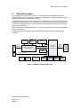
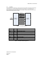
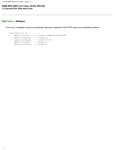
The ADM-XRC-5LX is provided with numerous clock sources, as shown in Figure 4 below:
PCI
Bus
PCI
RefClk
PCI-X
CLK
Bridge Cfg Ctl
(Coolrunner)
25.0 MHz
Osc
PCI
CLK
Bridge FPGA
(V4LX25)
REFCLK_200M
Ctl
LCLK
25.0 MHz
XTAL
200 MHz
Osc.
Local Bus
ICS8430
MCLK
MCLK
XRM_CLKIN
XRM
Connector
(Samtec)
Zero-delay
Buffer
(PLL)
Pn4 Connector
User FPGA
V5LX55/80/110
FF1153
CLK0 (P)
CLK1 (N)
CLK2 (P)
CLK3 (N)
CLK4 (P)
KEY
CLK5 (N)
Global Clock Inputs
Clock Capable I/O
CLK6 (P)
CLK7 (N)
Figure 4 Clock Structure
4.5.1. LCLK
The Local Bus can be used at up to 80 MHz and all timing is synchronised to LCLK between
the Bridge and User FPGAs. LCLK is generated from a 200MHz reference by a DCM within
the bridge FPGA. The minimum LCLK frequency (determined by the DCM specification) is
32MHz.
The LCLK frequency is set by writing to the board control logic. (See SDK for details and
example application).
Note: If the user FPGA application includes a DCM driven by LCLK (or one of the other
programmable clocks), the clock frequency should be set prior to FPGA configuration.
ADM-XRC-5LX User Manual
Version 2.0
Page 7