1
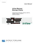
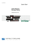
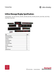
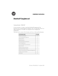
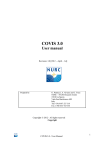
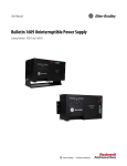
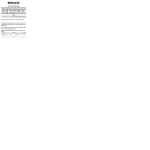
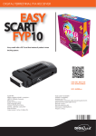
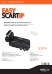
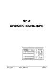
Installation Instructions
InView Marquee Message Display
Catalog Numbers 2706-P92C, 2706-P94C
Topic
Page
Important User Information
2
Wiring and Safety Guidelines
3
Hazardous Location Considerations
4
Catalog Number Explanation
5
Mount the 2706-P92C and 2706-P94C Displays
6
Back-to-back Mounting
7
Connect the 2706-P92C and 2706-P94C Displays
8
Dip Switch Information
12
Additional Information
18
Legacy Communications Board Kit
13
Compact Flash Card
14
2706-P9x Temperature Protection
14
Replace the Battery in the InView Message Displays
15
Specifications
17
2
InView Marquee Message Display
Important User Information
Solid state equipment has operational characteristics differing from those of electromechanical equipment.
Safety Guidelines for the Application, Installation and Maintenance of Solid State Controls (Publication
SGI-1.1 available from your local Rockwell Automation sales office or online at
http://literature.rockwellautomation.com) describes some important differences between solid state
equipment and hard-wired electromechanical devices. Because of this difference, and also because of the
wide variety of uses for solid state equipment, all persons responsible for applying this equipment must
satisfy themselves that each intended application of this equipment is acceptable.
In no event will Rockwell Automation, Inc. be responsible or liable for indirect or consequential damages
resulting from the use or application of this equipment.
The examples and diagrams in this manual are included solely for illustrative purposes. Because of the many
variables and requirements associated with any particular installation, Rockwell Automation, Inc. cannot
assume responsibility or liability for actual use based on the examples and diagrams.
No patent liability is assumed by Rockwell Automation, Inc. with respect to use of information, circuits,
equipment, or software described in this manual.
Reproduction of the contents of this manual, in whole or in part, without written permission of Rockwell
Automation, Inc., is prohibited.
Throughout this manual, when necessary, we use notes to make you aware of safety considerations.
WARNING
IMPORTANT
ATTENTION
Identifies information about practices or circumstances that can cause an explosion in
a hazardous environment, which may lead to personal injury or death, property
damage, or economic loss.
Identifies information that is critical for successful application and understanding of
the product.
Identifies information about practices or circumstances that can lead to personal injury
or death, property damage, or economic loss. Attentions help you identify a hazard,
avoid a hazard and recognize the consequences.
SHOCK HAZARD
Labels may be on or inside the equipment, for example, a drive or motor, to alert
people that dangerous voltage may be present.
BURN HAZARD
Labels may be on or inside the equipment, for example, a drive or motor, to alert
people that surfaces may reach dangerous temperatures.
Publication 2706-IN016D-EN-P - February 2009
InView Marquee Message Display
3
Wiring and Safety Guidelines
Install the InView display conforming to NFPA 70E, Electrical Safety Requirements
for Employee Workplaces. In addition to the NFPA general guidelines, refer to the
following:
Careful cable routing helps minimize electrical noise. Route incoming power to the
module by a separate path from the communication cables.
TIP
WARNING
Do not run communications wiring and power wiring in the same conduit.
SHOCK HAZARD
• Maintain separation of circuits. Route the incoming power directly to the power
connection terminal block.
• Do not run the power wiring over the logic board or optional Legacy Communication
board.
Where communication and wire paths must cross, make their intersection
perpendicular.
Grounding helps limit the effects of noise due to electromagnetic interference
(EMI). To avoid problems caused by EMI, properly ground all equipment and use
shielded cables.
IMPORTANT
Power wiring must be in accordance with Class I, Division 2 wiring methods (Article
501-4(b) of the National Electrical Code, NFPA70) and in accordance with the local
authority having jurisdiction.
Publication 2706-IN016D-EN-P - February 2009
4
InView Marquee Message Display
Hazardous Location Considerations
This equipment is suitable for use in Class I, Division 2, Groups A, B, C and D or
non-hazardous location only. The following WARNING statement applies to use in
hazardous locations.
The following information applies when operating
this equipment in hazardous locations.
Informations sur l’utilisation de cet équipement en
environnements dangereux.
Products marked “CL I, DIV 2, GP A, B, C, D” are suitable for use in
Class I Division 2 Groups A, B, C, D, Hazardous Locations and
nonhazardous locations only. Each product is supplied with
markings on the rating nameplate indicating the hazardous
location temperature code. When combining products within a
system, the most adverse temperature code (lowest “T” number)
may be used to help determine the overall temperature code of
the system. Combinations of equipment in your system are subject
to investigation by the local Authority Having Jurisdiction at the
time of installation.
Les produits marqués “CL I, DIV 2, GP A, B, C, D” ne conviennent
qu'à une utilisation en environnements de Classe I Division 2
Groupes A, B, C, D dangereux et non dangereux. Chaque produit
est livré avec des marquages sur sa plaque d'identification qui
indiquent le code de température pour les environnements
dangereux. Lorsque plusieurs produits sont combinés dans un
système, le code de température le plus défavorable (code de
température le plus faible) peut être utilisé pour déterminer le
code de température global du système. Les combinaisons
d'équipements dans le système sont sujettes à inspection par les
autorités locales qualifiées au moment de l'installation.
WARNING
WARNING
EXPLOSION HAZARD • Do not disconnect equipment
unless power has been removed
or the area is known to be
nonhazardous.
• Do not disconnect connections to
this equipment unless power has
been removed or the area is
known to be nonhazardous.
Secure any external connections
that mate to this equipment by
using screws, sliding latches,
threaded connectors, or other
means provided with this product.
• Substitution of components may
impair suitability for Class I,
Division 2.
• If this product contains batteries,
they must only be changed in an
area known to be nonhazardous.
AVERTISSEMENT
RISQUE D’EXPLOSION –
• Couper le courant ou s'assurer
que l'environnement est classé
non dangereux avant de
débrancher l'équipement.
• Couper le courant ou s'assurer
que l'environnement est classé
non dangereux avant de
débrancher les connecteurs. Fixer
tous les connecteurs externes
reliés à cet équipement à l'aide
de vis, loquets coulissants,
connecteurs filetés ou autres
moyens fournis avec ce produit.
• La substitution de composants
peut rendre cet équipement
inadapté à une utilisation en
environnement de Classe I,
Division 2.
• S'assurer que l'environnement est
classé non dangereux avant de
changer les piles.
This product contains a lithium battery (catalog number 2711P-RY2032). There is a
danger of explosion if it is incorrectly replaced. Replace only with the indicated type. Do
not replace the battery unless the area is known to be nonhazardous.
Do not dispose of the battery in a fire or incinerator. Dispose of used batteries in
accordance with local disposal regulations.
Publication 2706-IN016D-EN-P - February 2009
InView Marquee Message Display
5
Catalog Number Explanation
2706-P 9 2 C
Bulletin Number
2706-P = InView
Marquee Display
Display Height
(max character height)
9 = 9 in. (228.6 mm)
max display character
Display Length
Large Marquee
2 = Short Case (appx.
0.91 m, 3 ft) with Std
LED Pitch
4 = Long Case (appx.
1.83 m, 6 ft) with Std
LED Pitch
LED Color
C = Tri-color
Publication 2706-IN016D-EN-P - February 2009
6
InView Marquee Message Display
Mount the 2706-P92C and 2706-P94C Displays
1. Attach the two sign brackets to a wall, ceiling, or other surface.
Be sure to place the brackets so the bracket flanges face appropriately as
shown below. Mount the brackets the following distance apart (measured
from the center of the mounting holes in each bracket):
Mounted so flanges are hidden
behind the sign.
2706-P92C:103.0 cm (40.55 in.)
2706-P94C: 194.4 cm (76.55 in.)
Mounted so flanges show on the
sides of the sign.
2706-P92C: 107.8 cm (43.22 in.)
2706-P94C: 201.2 cm (79.22 in.)
Wall or
ceiling
Sign brackets, facing out from the sign
Sign brackets, facing in behind the sign
Do not install the sign directly to drywall or plasterboard. The sign must be fastened to a
surface capable of supporting at least four times the weight of the sign.
IMPORTANT
2. Mount the sign on the sign brackets using the hex bolts supplied. Insert the
bolts into the far single holes first, until the desired viewing angle is
determined.
5.40
.40
.344 x .688
OB ROUND
.344 x .688
OB ROUND
0.572
1.33
.344 x .688 .344 x .688
OB ROUND OB ROUND
0.572
.88
.88
Ø.281
1.50
1.50
.76
.40
.135
4.63
1.33
4.63
10°
1.50
1.50
.76
.40
.135
1.33
Left Bracket
1.33
1.75 1.75
0.572
Ø.281
7.635
.40
0.572
1.75 1.75
10°
5.40
7.635
Right Bracket
Ceiling
Wall
Hex Bolt
for Single
Hole
Publication 2706-IN016D-EN-P - February 2009
InView Marquee Message Display
7
3. Tilt the sign to select a viewing angle. To hold the sign in place, inset the
remaining bolts into the desired viewing angle hole on each bracket.
Ceiling
Wall
End View,
Wall/Ceiling
Mounted
TIP
Desired Viewing
Angle Hole
Keep a minimum 2.54 cm (1.0 in.) clearance on all sides of the sign for adequate
ventilation.
Back-to-back Mounting
1. Attach the brackets to the sign in the ceiling mount position. Use the hex
bolts supplied.
Attach chains here
First
Sign
First
Mounting
Bracket
Second
Sign
Second
Mounting
Bracket
2. Match the signs together back-to-back. Connect them together using a total
of six 5/16” bolts and nuts (not supplied).
3. Use chains (not supplied) to hang the signs from the ceiling. Attach the
chains to the top mounting holes of the bracket.
TIP
Use chains capable of supporting 4 times the total weight of the signs.
Publication 2706-IN016D-EN-P - February 2009
8
InView Marquee Message Display
Connect the 2706-P92C and 2706-P94C Displays
WARNING
HAZARDOUS VOLTAGE
• Contact with high voltage may cause death or serious injury. Always disconnect
power to sign prior to servicing.
• Maintain Separation of circuits. Route the incoming power directly to the power
connection terminal block.
• Do not run the power wiring over the logic board or optional Legacy Communication
board.
1. Open the front of the sign case by turning the half-turn latches to the left
with a large screwdriver. (On the 2706-P92C, there are 3 half-turn latches; on
the 2706-P94C there are 5.) Carefully let the front of the case drop forward.
Front View, closed
Half-turn Latches on an 2706-P94C Sign
Front View, open
Electrical
Opening
Power Connection
Terminal Block
Communication
Opening
2. Feed electrical cable through 1/2” water-tight conduit, the outside end of the
connector (supplied), the electrical opening in the sign case, and then
through the inside end of the connector. Screw the inside and outside ends
of the connector together until water-tight.
TIP
Use either of the two holes nearest the power connection terminal block.
Publication 2706-IN016D-EN-P - February 2009
InView Marquee Message Display
9
Rubber Gasket
Front View
Conduit
Connector,
Outside End
Sign Case,
inside
Connector nut, with teeth
facing the sign case.
3. Strip the electrical wires back 1/4”. Insert the wires into the appropriate
terminal connection and tighten the screw to 0.79 N•m (7 lb•in). The
terminal block is UL rated for wire ranges of 14 to 8 AWG.
Line
(Hot)
BLACK
Ground
GREEN
w/
Yellow
Neutral
(Line 2):
WHITE
GROUND
LINE 2 OR
NEUTRAL
GROUND
LINE 2 OR
NEUTRAL
LINE 1
Power connection
LINE 1
208 - 240 VAC INPUT
4. Remove the necessary hole plugs before connecting the communications
cables.
Publication 2706-IN016D-EN-P - February 2009
10
InView Marquee Message Display
5. Connect the incoming communication wires per the tables below.
ATTENTION
Use shielded Ethernet cable. Shielded Ethernet cable is required to maintain noise
immunity.
The 2706-P Cable1 is used for downloading messages only and must be removed after
downloading is complete.
TB2 is used for supplying power to the optional InView Legacy
Communication board kit.
Communication
Openings
Ethernet
TB1
RJ-12
TB2
TB3
TB1 - RS-485
1.GND
4.CH A
2.SHLD
5.CH B
3.COMM
6.TERM
TB2 - Aux +5V
1.+5V
2.GND
TB3 - RS-232
1.TXD
4.CTS
2.RXD
5.GND
3.RTS
6.EGND
Publication 2706-IN016D-EN-P - February 2009
InView Marquee Message Display
11
Ethernet (RJ-45)(1)
(1)
1.TD+
5.NC
2.TD-
6.RD-
3.RD+
7.NC
4.NC
8.NC
Use shielded Ethernet cable to maintain noise immunity.
Download Port (RJ-12)(1)
(1)
1.Aux +5V
4.RX
2.NC
5.NC
3.TX
6.GND
The 2706-PCable1 is used for downloading messages only and must be removed after downloading is complete.
6. Carefully close the front of the sign case and turn the half-turn latches to the
right with a large screwdriver.
Publication 2706-IN016D-EN-P - February 2009
12
InView Marquee Message Display
Dip Switch Information
There are two dip switches located on the controller board, Switch 1 and Switch 2.
Switch 2
Switch 1
Switch 1
Switch 1 is used to configure the display - RS485 echo enable, baud rate settings,
and display size.
• Position 1 enables or disables the echo function.
Enabling the RS485 echo function allows any packets that come in on COM
0 (download, RJ-12 port), COM 1 (RS-232, TB3 port), and the Ethernet
TCP/IP port to be sent out the RS485 port. This allows Ethernet TCP/IP and
other communication protocols to be converted to RS485 by a single P92 or
P94 and then sent out to multiple RS485 networked displays.
TIP
Only enable the echo function on one P9x display.
• Positions 3 and 4 set the baud rate. (See page 13 for default positions.)
If both switches are off, the baud rate can be set via the InView Messaging
software. The dip switches take priority over the software setting. If the baud
rate is set to 19,200 using the software (positions 3 and 4 set to off) and then
set to 9600 using switch 1 (position 3 on and 4 off), the baud rate would
then be 9600. Also, once positions 3 and 4 are used to set the baud rate and
then they are switched off, the baud rate setting will remain until it is
changed by software or a different dip switch setting.
• Position 5 is used to set the display size. This is set by the factory.
• Position 6 is used to turn on diagnostics.
• Position 7 disables download message.
Publication 2706-IN016D-EN-P - February 2009
InView Marquee Message Display
13
Switch 2
Switch 2 is used to set the serial address of the display. Position 1 is the LSB of the
address and position 8 is the MSB of the address.
• If position 1 is on and all other positions are off, the display address will be
1.
• If position 8 is on and all other positions are off, the display address will be
128.
• If all positions are set to off, the serial address can be set using the InView
Messaging software.
The dip switch setting takes priority over the software setting. If the serial address is
set to 2 using the software (all the dip switches set to off) and then switch 2 is used
to set the serial address to 3 (position 1 and 2 set to on and the remaining positions
set to off), the serial address will then be 3. Also, once Switch 2 is used to set the
serial address and then all switch positions are set to off, the serial address setting
remains until it is changed by software or the dip switch is set.
Not
RS485 Used
Echo
Not
Used
LSB
Size
ON = P92C
ON = Disable
OFF = P94C
Download
Message
ON =
Baud Rate
Diagnostics
3
4
OFF OFF = Software Default
ON OFF = 9600
OFF ON = 19200
ON ON = 38400
MSB
Display Address
Switch
1
2
3
4
5
6
7
8
Value
1
2
4
8
16
32
64
128
Legacy Communications Board Kit
There is an optional Legacy Communications Board Kit available for the P9 series
displays. There are a total of six board kits: Remote I/O, DH+, DH-485, ControlNet,
DeviceNet, and EtherNet/IP. The Legacy Communications Board Kit converts the six
protocols to RS-232. The board kit mounts on the four PEM spacers that are
Publication 2706-IN016D-EN-P - February 2009
14
InView Marquee Message Display
attached to the internal mounting plate. See publication 2706-IN015 for more
information on how to install the board kit.
PEM Spacers
Compact Flash Card
This product uses a Type I Compact Flash Card for message file storage.
2706-P9x Temperature Protection
InView P92C and P94C signs have automatic temperature controls that help to
protect the sign from damage when the internal temperature of the sign is too hot
to continue normal operation.
• If the internal temperature of the sign reaches a pre-determined “dimming
point”, the LED output from the sign is forced into a 50 percent reduced
power mode, effectively dimming the brightness of LED output by about 50
percent.
• If the internal temperature of the sign continues to increase, another sensing
circuit will execute an automatic shut down to protect the sign from damage.
The LED output from the sign is turned off. Two LED pixels will flash in the
lower right corner, indicating an auto-shutdown has occurred.
• The dimming and shutdown points are listed in the table below. Once the
temperature drops below the auto-shutdown threshold, the LED output is
turned on at the dimming level. Once the temperature drops below the
dimming threshold, auto-dimming is disabled and the LED brightness is back
to 100 percent.
Model
Dimming Point
Auto-shutdown On
2706-P92C
55 °C (131 °F)
75 °C (167 °F)
2706-P94C
55 °C (131 °F)
75 °C (167 °F)
Publication 2706-IN016D-EN-P - February 2009
InView Marquee Message Display
TIP
15
Take into account the effects of ambient temperature when evaluating mounting
locations for the sign. You should always maintain recommended clearance distances
around the sign and avoid poorly ventilated mounting locations that could be subject to
radiation, convection, conduction or other thermal transfer effects.
Replace the Battery in the InView Message Displays
The terminal contains a lithium battery, which is intended to be replaced during the
life of the product.
ATTENTION
The clock module contains lithium. Do not dispose the battery in a fire or incinerator or
the clock module may explode. Follow disposal regulations in your area for lithium
battery disposal.
At the end of its life, the used battery should be collected separately from any unsorted
municipal waste and recycled.
Publication 2706-IN016D-EN-P - February 2009
16
InView Marquee Message Display
Follow these steps to replace the battery in the InView 2706-P92C or 2706-P94C
message displays.
1. Disconnect power from the message display.
2. Turn the half-turn latches all the way to the left until they hit the stop.
3. Carefully lower the door.
Front View,
closed
Front View, open
Half-turn Latches on an 2706-P94C Sign
Circuit
Board
4. Locate the battery on the circuit board.
Battery
Press down here to pop battery out.
5. Press down firmly on the middle part of battery retainer clip.
The battery will pop out.
6. Slide the new battery under the 3-prong holder and push down.
7. Raise the door and turn the half-turn latches all the way right until they hit
the stop and the door is pulled in.
Publication 2706-IN016D-EN-P - February 2009
InView Marquee Message Display
17
Specifications
2706-P92C
2706-P94C
Display
Display type
LED matrix: Tri-Color (C)
Display window size
(W x H)
91.4 x 24.4 cm (36 x 9.6 in.)
182.9 x 24.4 cm (72 x 9.6 in.)
Display array
120 x 32 pixels
240 x 32 pixels
Center to center pixel spacing
(pitch)
0.76 cm (0.3 in.)
Number of lines
1…5
Lines of text/character height/
minimum characters per line
1 line/9.6 in./13(1)
1 line/9.6 in./26(2)
2 line/4.5 in./13(1)
2 line/4.5 in./26(2)
3 line/3.0 in./13(1)
3 line/3.0 in./26(2)
4 line/2.1 in./20(1)
4 line/2.1 in./40(2)
5 line/1.5 in./24(1)
5 line/1.5 in./48(2)
Character set
Standard and Extended ASCII
Approximate viewing distance
137 m (450 ft)
Electrical and Environmental
Input voltage
100…240V AC; 50/60 Hz
Temperature, operating
0…50 °C (32…122 °F)
Humidity
5…95% noncondensing
Ratings
Designed to meet UL types 12 and 13
Designed to meet NEMA 4 Hose Down requirements
Certifications
cULus, CE and C-Tick
Enclosure weight, approx.
32 kg (70 lbs)
54.4 kg (120 lbs)
Enclosure dimensions
(W x D x H)
105 x 13 x 40 cm
196 x 13 x 40 cm
(41.14 x 5.25 x 15.9 in.) (1)
(77.2 x 5.25 x 15.9 in.) (2)
(1)
Display is available in short format (0.91 m, 3 ft).
(2)
Display is available in long format (1.83 m, 6 ft).
Publication 2706-IN016D-EN-P - February 2009
18
InView Marquee Message Display
Input Current Requirements for 2706-P92C and 2706-P94C
Line Voltage
(VAC)
Frequency (Hz)
100% Display
Load (Amp)
50% Display Load
(Amp)
25% Display Load
(Amp)
100 - P92C
50/60
3.6
2.1
1.3
100 - P94C
50/60
7.1
3.9
2.3
120 - P92C
50/60
2.9
1.7
1.0
120 - P94C
50/60
5.8
3.2
1.9
240 - P92C
50/60
1.4
0.9
0.6
240 - P94C
50/60
2.8
1.6
1.0
Display
Load
100%
Condition - All display pixels are lit in amber
Usage - Highly unlikely, use this value for sizing input power circuit
50%
Condition - 50% of the display lit in amber (screen full of 32 pixel amber ‘B’s)
Usage - Unlikely, not a typical display condition, may be seen with use of bitmaps
25%
Condition - Mixture of red, green and amber characters and spaces
Usage - Typical display load for most message types
Additional Information
For additional information on communication port wiring and display
configuration, refer to the InView Marquee Message Display User Manual,
publication 2706-UM016.
Publication 2706-IN016D-EN-P - February 2009
InView Marquee Message Display
19
Notes:
Publication 2706-IN016D-EN-P - February 2009
Rockwell Automation Support
Rockwell Automation provides technical information on the Web to assist you in
using its products. At http://support.rockwellautomation.com, you can find
technical manuals, a knowledge base of FAQs, technical and application notes,
sample code and links to software service packs, and a MySupport feature that you
can customize to make the best use of these tools.
For an additional level of technical phone support for installation, configuration and
troubleshooting, we offer TechConnect support programs. For more information,
contact your local distributor or Rockwell Automation representative, or visit
http://support.rockwellautomation.com.
Installation Assistance
If you experience a problem within the first 24 hours of installation, please review
the information that's contained in this manual. You can also contact a special
Customer Support number for initial help in getting your product up and running.
United States
1.440.646.3434
Monday – Friday, 8 a.m. – 5 p.m. EST
Outside United
States
Please contact your local Rockwell Automation representative for any
technical support issues.
New Product Satisfaction Return
Rockwell Automation tests all of its products to ensure that they are fully
operational when shipped from the manufacturing facility. However, if your
product is not functioning and needs to be returned, follow these procedures.
United States
Contact your distributor. You must provide a Customer Support case number
(call the phone number above to obtain one) to your distributor in order to
complete the return process.
Outside United
States
Please contact your local Rockwell Automation representative for the return
procedure.
InView, Allen-Bradley, Rockwell Automation, and TechConnect are trademarks of Rockwell Automation, Inc.
Trademarks not belonging to Rockwell Automation are property of their respective companies.
Publication 2706-IN016D-EN-P - February 2009
Supersedes Publication 2706-IN016C-MU-P - April 2004
PN-39896
Copyright © 2009 Rockwell Automation, Inc. All rights reserved. Printed in the U.S.A.