1
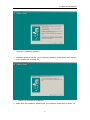
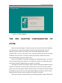
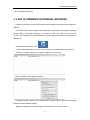
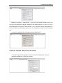
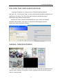
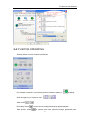
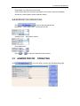
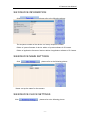
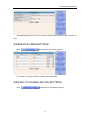
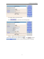
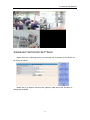
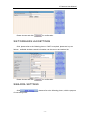
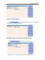
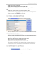
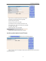
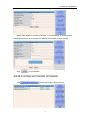
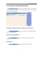
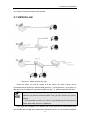
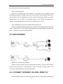
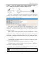
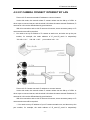
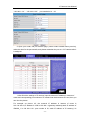
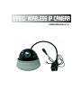
USER MANUALV1.0 IP Camera User Manual CATALOGUE THE 1ST CHAPTER DESCRIPTION OF PRODUCT........................................................................ - 1 1.1 PACKING........................................................................................................................................ - 1 1.2 THE LOWEST SYSTEM CONFIGURTION ............................................................................... - 1 1.3 FEATURES .................................................................................................................................... - 1 THE 2ND CHAPTER HE INSTALLATION OF IP CAMERA ............................................................ - 2 2.1 INSTALLATION OF PREPAREATION........................................................................................ - 2 2.2 HARDWARE INSTALLATION...................................................................................................... - 3 2.3 SOFTWARE INSTALLATION ...................................................................................................... - 3 THE 3RD CHAPTER CONFIGURATION OF IPCAM........................................................................ - 5 3.1 GET IP ADDRESS IN INTERNAL NETWORK .......................................................................... - 6 3.2 SOFTWARE EDITION UPDATE................................................................................................. - 7 3.3 LOGIN THE CONFIGURATION PAGE ...................................................................................... - 8 3.4 REAL-TIME MONITORING ......................................................................................................... - 8 3.4.1 VISITOR OPERATING ................................................. ..- 9 3.4.2OPERATOR OPERATING ............................................... - 10 3.5 ADMINISTRATOR OPERATING .......................................................................................... - 10 3.5.1 DEVICE INFORMATION ................................................ - 11 3.5.2 DEVICE NAME SETTINGS .............................................. - 11 3.5.3 DEVICE CLOCK SETTINGS............................................. - 11 3.5.4 DEVICE USER SETTINGS .............................................. - 12 3.5.5 MULTI-CHANNEL DEVICE SETTINGS ................................... - 12 3.5.6 BASIC NETWORK SETTINGS ........................................... - 14 3.5.7 WIRELESS LAN SETTINGS ............................................. - 15 3.5.8 ADSL SETTINGS ...................................................... - 15 3.5.9 UPNP SETTINGS ...................................................... - 16 3.5.10 DYNAMIC DOMAIN NAME SETTINGS .................................. - 16 3.5.11 MAIL SERVICE SETTINGS............................................. - 17 3.5.12 FTP SERVICE SETTINGS ............................................. - 17 3.5.13 ALARM SERVICE SETTINGS .......................................... - 18 3.5.14 SYSTEM SOFTWARE UPGRADE ...................................... - 19 3.5.15 BACKUP & RESTORE SETTINGS ...................................... - 20 3.5.16 RESTORE FACTORY DEFAULT SETTINGS ............................. - 20 3.5.17 DEVICE REBOOT..................................................... - 20 3.5.18 LOG ................................................................. - 20 3.5.19 RETURN ............................................................. - 21 THE 4TH CHAPTER HOW TO VIEW IP CAMERA ......................................................................... - 21 4.1 VIEW IN LAN................................................................................................................................ - 22 4.2 VIEW INTERNET ........................................................................................................................ - 23 2 IP Camera User Manual 4.2.1 CONNECT INTERNET VIA ADSL DIRECTLY .............................. - 23 4.2.2 IP CAMERA CONNECT INTERNET BY LAN............................... - 25 THE 5TH CHAPTER TECHNICAL PARAMETER ........................................................................... - 27 5.1 KEY FUNCTIONS ..................................................................................................................... - 27 5.2 KEY PARAMETERS ................................................................................................................... - 28 THE 6TH CHAPTER APPENDIX........................................................................................................ - 28 6.1 RESTORE FACTORY DEFAULT SETTINGS.......................................................................... - 28 6.2 TROUBLE SHOOTING............................................................................................................... - 29 - 3 THE 1ST CHAPTER DESCRIPTION OF PRODUCT 1.1 PACKING Packing in detail as follow (If find any missing part, please contact with your supplier immediately) 1.IP camera, bracket 2.Driver 3.Power adapter 4.B-B network cable 1.2 THE LOWEST SYSTEM CONFIGURTION The lowest system configuration of your PC when using this IP camera as below: 1.Pentium III CPU or above, 1Ghz frequency or higher 2.256M built-in memory or above 3.10-100M network card or above 4.Operating system: Windows XP, Windows 2000 or above; Install internet explorer 7.0(or above) browser, we suggest you to use internet explorer 7.0 browser for view. 1.3 FEATURES Easy installation —— IP CAMERA is an independent system, with built-in CPU and picture decoder; Just one power adapter and LAN connection can make it work Suitable for home, office and public place —— No matter monitoring of home, office or public place, or for amusement only, this IP camera can match your needs Support multiform protocols — TCP/IP network protocol, SMTP protocol, HTTP protocol and other protocols related to internet Simple configuration —With standard web browser in administrator interface. Administrator can control and manage IP camera by LAN or Internet IP Camera User Manual Viewing/Recording — Clear user interface to view real-time pictures. Even when you leave for a while, IP CAMERA will record the pictures and transfer files to your PC. Files will be saved in the form of standard windows media, suitable for extensive application program Dynamic Monitoring — Capturing any tiny picture and send to your mail box.IP CAMERA will automatically compare the two continuous pictures and find out the changes caused by moving. Support DDNS — In order to view the pictures by internet, users must know the gateway IP address when using IP camera. However, if your gateway IP address is dynamic, you must have dynamic domain server. As usual, many of the gateway don’t support dynamic domain service, so it is limited when using IP camera. User management — if required, only authorized users can view real-time video and before that, users must enter their user names, passwords. Maximum users: 8 persons THE 2ND CHAPTER INSTALLATION OF IP CAMERA Quickly view the installation manual, after finishing the procedures step by step, IP camera will work accordingly. IP camera can be used in LAN, you will find the IP address in LAN by carrying out IP camera tool program on PC, then input this IP address into the IE browser address field(such as http://192.168.1.188),so it can connect IP camera and camera interface can be shown on browser page. For external network visit, a prior suitable configuration of IP camera in LAN is required, please refer to the instructions in the following chapters. 2.1 INSTALLATION OF PREPAREATION Please make sure you have already read the user manual carefully and know well about the functions and configurations of IP camera before installation. Then, use the enclosed network cables to network to connect IP camera to internet, via router or switch. Please prepare the router and switch by yourself. -2- IP Camera User Manual 2.2 HARDWARE INSTALLATION This part is for introducing how to finish hardware installation and physical connection of IP camera. After it, please connect power supply, IP camera will start work and the indicator light will shine. 1.Install IP camera at the place where monitoring required 2.Connect network Connect IP camera with Hub(10/100M) or switch(10/100M),insert one end of the network cable into RJ45 port, the other end into router or switch. Indicator light at RJ45port will flash under normal condition 3. Connect to the power supply Please use the enclosed power adapter in package to connect the IP camera and power supply, otherwise you will damage the hardware 1. Make sure the length of the network cable is within validity range. If over 100 meters, please use signal amplifier 2. In order to avoid damages on hardware, please use the power adapter we supply 3. If you connect PC to IP camera directly, please make sure the crossover cable is used. 4.Check LED light After connect to the power supply, IP camera will start work and the small yellow light at the back of it will shine. In dark condition, you will see the light at the front of camera.22 infrared lights will be as lamp-house to let you see clear picture in dark 2.3 SOFTWARE INSTALLATION Please use the enclosed IPCamSetup.exe software to start initial installation on your PC. After it, IP camera Tool will search all IP address in the same network space automatically. 1.Please use the enclosed driver, then you will see the welcome interface of installation program. 2.Introduction interface of installation will be shown. After read it, press ”next” to continue installation. Please refer to picture2.4 -3- IP Camera User Manual Picture2.4: installation interface 1 3.Installation guidance will help you to finish the installation. Please press “Next” buttons in turn, please refer to picture 2.5 Picture 2.5: Continue the installation 4.When finish the installation, please restart your computer. Please refer to picture 2.6 -4- IP Camera User Manual Picture 2.6: finish installation THE 3RD CHAPTER CONFIGURATION OF IPCAM After finish the 2nd chapter, IP camera can work in LAN. We can find the IP address of IP Camera by IP camera Tool program and visit IP camera by browser. (input IP address and port number of IP camera into the IE browser address field, such as “http://192.168.1.112:100”,Then press” enter”. If the port number is 80, then you can input IP address, http://192.168.1.112 directly, without port number), Please note that our factory default setting of the port number is 80. Now we can configure IP camera by operating web configuration page. If you want to view the monitoring picture by browser, or to operate IP camera web configuration page, you should know the IP address and port number of IP camera. We supply IP Camera Tool Program, which is used for searching IP address and port number of IP camera in LAN only (both IP camera and our PC are in the same network space), but not for searching IP address and port number of IP camera in external network (IP camera and our PC are not in the same network space).If we want to visit IP camera through external network, we must configure IP camera in LAN at first. About how to make a external network visit or detail information of setup, please refer -5- IP Camera User Manual to the following descriptions 3.1 GET IP ADDRESS IN INTERNAL NETWORK Please pay attention to the camera power and available connection before getting IP address. Used LAN or PC need to support DHCP (dynamic IP allocation), because the camera's default setting is dynamic accessing to IP address; if the used LAN or PC is no such function, the camera will not be searched out (at this time pls operate it according to the dialog box) Double press IP Camera Tool. As the following dialog box on PC: You will see the IP address after more than 10 seconds, if camera connect to the power supply just for a minute. Check IP Camera main property setting If dialog message shows IP camera not in same network with PC, pls click mouse right button and select network setting. Manually changed the network setting to be same as PC, as picture show: -6- IP Camera User Manual Please do not choose “ Using DHCP”, if your LAN or PC doesn’t support DHCP. You can set up the camera IP address according to the network space of LAN or PC, but it should be different from that of other devices or PC in the same network space(the first 3 items and subnet mask should be same).You can change the port setting on the webpage only. If LAN or PC supports DHCP, then pls choose “Using DHCP” 3.2 SOFTWARE EDITION UPDATE IP Camera supports the upgrade of system software and application software, application software is for interface upgrade. -7- IP Camera User Manual 3.3 LOGIN THE CONFIGURATION PAGE If input the IP address of IP Camera into the IE browser address field like http://192.168.1.188 and press “Enter” or directly double press the listed IP address in the dialog box of IP Camera Tool, IE browser will be start up automatically and the administrator login window will also appear. Input the user name, password (the defaulted user name: admin, the defaulted password: leave it blank), click “sign in” to view the monitoring page (supports synchronous view of maximum 8 users )。 3.4 REAL-TIME MONITORING Notice: If no picture shown for the first-time use, you can set the user-defined security grade of option “Internet” of IE browser: namely, unsigned control can be set up as the status of “startup prompt” -8- IP Camera User Manual 3.4.1 VISITOR OPERATING Working status for each channel as followed: For example: channel 1 is monitoring (motion detection status), if Click the right key for 4-picture view: flickering. . Video on/off Recording: Press Take picture: press to save the recording files through appointed path. to capture and save pictures through appointed path. -9- IP Camera User Manual Default path: my computer/my document Green button: Normal connection and display; Gray button: camera unavailable Red button: camera alarm (motion detection alarm) 3.4.2OPERATOR OPERATING Click , to set up following parameters Resolution: VGA(640 X 480)/ QVGA(320 X 240) working mode: 50Hz/60Hz/ outdoor photo parameters: Press 3.5 Click or to adjust the brightness and contrast ADMINISTRATOR OPERATING in monitor page, to enter into administrating page - 10 - IP Camera User Manual 3.5.1 DEVICE INFORMATION Click please refer to the following picture: The sequence number of the device: our factory sequence number. Edition of system firmware of device: edition of system software of IP Camera Edition of application firmware of device: edition of application software of IP Camera 3.5.2 DEVICE NAME SETTINGS Click , please refer to the following picture: Name: set up the name for the camera 3.5.3 DEVICE CLOCK SETTINGS Click , please refer to the following picture: - 11 - IP Camera User Manual Automatically get time from PC or server, It will get time from PC if didn’t connect to LAN. 3.5.4 DEVICE USER SETTINGS Click please refer to the following picture IP Camera can set up maximum 8 users and permissions 3.5.5 MULTI-CHANNEL DEVICE SETTINGS Click please refer to the following picture - 12 - IP Camera User Manual For example: add the 2nd channel image Click , please refer to the following picture: Fill Host,Http Port ,User, Password of IP Camera Input the Host, Http Port, User, Password, Click , then , and then to switch to 4-picture monitoring mode, as following: - 13 - IP Camera User Manual 3.5.6 BASIC NETWORK SETTINGS Please refer to the following picture. For example, the IP address of this device can be set up as follows: Please set up IP address, subnet mask, gateway, DNS server well. Dynamic IP setting also available - 14 - IP Camera User Manual Please choose and click for confirmation. 3.5.7 WIRELESS LAN SETTINGS Click, please refer to the following picture. If WIFI is required, please set it up as follows:available wireless network information can be can out and make a list. for confirmation. Please choose and click 3.5.8 ADSL SETTINGS Click , please refer to the following picture, with the purpose of connecting ADSL. - 15 - IP Camera User Manual 3.5.9 UPNP SETTINGS Click , please refer to the following picture. It is unnecessary if the router does not have this kind of function. 3.5.10 DYNAMIC DOMAIN NAME SETTINGS Click , please refer to the following picture: DDNS Service: Fill in the web address for applying the domain name - 16 - IP Camera User Manual DDNS User: Fill in the domain name DDNS Password: Fill in the password of the domain name DDNS Domain Name: DDNS domain name will automatically get the IP if connect well. DDNS Status: Display the status of connecting the domain name It will be necessary to set up this function if you want to make a visit through Internet. Please choose and click for confirmation 3.5.11 MAIL SERVICE SETTINGS Click , please refer to the following picture This is with mail alarm function: if any movement was detected, it will send message to the email box which we have set up. Sender: Fill in the e-mail address of senders Receiver: Fill in the e-mail address of the receiver (4 receivers’ e-mails can be set up synchronously SMTP Server: Fill in the server address of the sender’s e-mail SMTP User Fill in the user name of the sender’s e-mail SMTP Password: Fill in the password of the sender’s e-mail This function can be effect only if the camera has been connected to Internet; It is necessary that the newly-revised password will be same as the e-mail password 3.5.12 FTP SERVICE SETTINGS Click , please refer to the following picture: - 17 - IP Camera User Manual This function is to upload the pictures to the Internet. FTP Server: Fill in the web site to be uploaded FTP Port: Fill in the FTP Port FTP User: Fill in the FTP user name FTP Password: Fill in the password of the FTP user FTP Upload Folder: Fill in the file name to be uploaded FTP Mode: Select PORT Upload Image Now: Click it if needed Upload Interval: setup the interval; Unit : second 3.5.13 ALARM SERVICE SETTINGS Click , please refer to the following picture Select the alarm mode. For example, if select motion detection mode, you can refer to the following pictures: - 18 - IP Camera User Manual Select Alarm Mode by yourself: IO linkage, or e-mail sending, or image upload. Following information is an example for selecting the method of email sending: Click for confirmation 3.5.14 SYSTEM SOFTWARE UPGRADE Click , please refer to the following picture: - 19 - IP Camera User Manual 3.5.15 BACKUP & RESTORE SETTINGS Click , please refer to the following picture. It can Backup the IP camera configuration. It will turn to your Restore settings it there is something wrong with your IP camera configuration. 3.5.16 RESTORE FACTORY DEFAULT SETTINGS Click can be restored accordingly , and re-start the device, the factory default settings 3.5.17 DEVICE REBOOT Click , it will re-start the device, but former settings unchanged. 3.5.18 LOG Click , list out all user login information in time - 20 - IP Camera User Manual 3.5.19 RETURN Click , it will return to the monitoring interface THE 4th CHAPTER HOW TO VIEW IP CAMERA After adjust IP camera on the web page, you can visit it through internet accordingly. This will be divided into two conditions: LAN view and Internet view. About internet view, it will be divided into the modes of dynamic connection and static connection, on the basis - 21 - IP Camera User Manual of IP camera connection method with internet. 4.1 VIEW IN LAN Picture 4.1: Sketch map of Lan view Under this mode, PC and IP camera is in the same LAN, both of them can be connected with each other by network cable (picture 4.1-1),hub(picture 4.1-2) or switch. IP address(4.1-3).IP address is a private one(like 192.168.1.*), subnet mask:255.255.255.0 1.If you choose the connection like 4.1-1(in sketch map of LAN view), please make sure you will use crossover cable. If not, you can’t connect it to your IP camera) 2.Hub and switch in picture 4.1-2 and 4.1-3(in sketch map of LAN view),can replace each other, there is no difference. First, finish the installation of IP camera Tool as the steps above-mentioned(anyway, you should have to install the IP camera tool well at first, then you can find the IP address, - 22 - IP Camera User Manual and make the other advanced operations) View via IP camera Tool” After run IP Camera Tool of IP camera, it will search the IP camera in LAN automatically and show IP address and name on the window, you just need to double click this IP address, the PC will display IE browser window and the login interface, input user and password, you can enter into monitoring page for view. Please remember the IP address, it is surely required if you hope to use webs browser for view Input Ip address into IE browser address field for direct view Input the IP address and port number of IP camera into IE browser address field, click “enter”, input account no. and relative password,then you can see images on web.Note:If port no. is 80,you can input IP address directly 4.2 VIEW INTERNET Picture 4.2: Internet view IP camera When PC and IP camera is not in the same network space, it is set at the two ends of internet, show as picture 4.2, this requires to setup IP camera correctly based on the connection method between IP camera and internet 4.2.1 CONNECT INTERNET VIA ADSL DIRECTLY When IP camera connect to internet through the dial-up of ADSL(show as follows),its - 23 - IP Camera User Manual IP address is dynamic and changeable. Every connection to internet via the dial-up of ADSL,IP camera will get a temporary and different IP address from ISP In this case, we can fill ADSL’s user name and password on IP camera interface and choose the option of “use dial-up of ADSL for connection”. The option of “ use email to inform ADSL’s IP address”, picture as below When camera is powered, the dial-up of ADSL will automatically run to connect internet, ISP will assign a dynamic IP address to the camera while send this address to user by email. User can use IP address and port no. to visit IP address and monitor the images via IE browser. As the IP address of internet is changeable, namely, ISP will assign a new IP address to router for each dial-up, obviously it is not easy for user to remember. So we can make use of DDNS to bind the IP address with a domain name together, which is applied by user and easy to remember, then it becomes simple for us to input domain name and port no. in browser. How to use DDNS 1. Register DDNS service with the supplier, then you will get a domain name together with an account and a password 2. Input correct DDNS settings on the page of IP camera (refer to 3.5.10) 3. When the internet IP address is changed, IP camera will connect to DDNS server automatically, advising itself the new IP address 4. User only need to input domain name assigned by DDNS server into IE browser address field, browser will connect IP camera automatically 1.;You need to apply for this service at DDNS server before using 2. You need to operate as DDNS service supplier says - 24 - IP Camera User Manual 4.2.2 IP CAMERA CONNECT INTERNET BY LAN Picture 4.5 IP camera use static IP address to connect Internet Under this mode, the network where IP camera exists use the dial-up of ADSL or other ways to connect Internet, and the whole LAN share the same external IP address, IP cameras in LAN can be differentiated by port Numbers. With this connection and to visit IP camera via internet, some necessary setup on IP camera and router will be required: 1. You need to set up IP address of IP camera as static one, and also set up the port number, for example, the static address of IP_cam1,IP_cam2 is respectively “192.168.1.101”,“192.168.1.102”, port number is 81,82 Picture 4.5 IP Camera use static IP address to connect Internet Under this mode, the network where IP camera exists use the dial-up of ADSL or other ways to connect Internet, and the whole LAN share the same external IP address, IP cameras in LAN can be differentiated by port Numbers. With this connection and to visit IP camera via internet, some necessary setup on IP camera and router will be required: 1. You need to set up IP address of your IP camera as static one, and also set up the port number, for example, the static address of IP_cam1,IP_cam2 is respectively - 25 - IP Camera User Manual “192.168.1.101”,“192.168.1.102”, port number is 81,82 2. Open your router, find port transfer page ( some routers named dummy service), make the rules for the port transfer, and please remember the port no. of IP camera after It is assigned 1. After finish the settings of IP camera, input the external IP address in Internet of router and corresponding port numbers of IP camera into the browser at PC end, then you can view the picture. For example: as picture 4.5, the external IP address in Internet of router is 219.134.248.11,IP address in LAN is 192.168.1.1(gateway address),static IP address of IP606W_1 is 192.168.1.101,port number is 81, static IP address of IP camera_2 is - 26 - IP Camera User Manual 192.168.1.102,port No. is 82. Set up the port transfer of the router as follows: camera transfer port start port IP address IP Camera_1 81 81 192.168.1.101 IP Camera_2 82 82 192.168.1.102 When user input http:// 219.134.248.11:81 on PC, router receives application and automatically transfers to 192.168.1.101,after that, IP camera 1 and PC will be connected together, then user can view IP camera through the browser on PC. Similarly, we need to know and remember the IP address in Internet of the whole LAN, as below picture, IP address in internet is “219.134.248.11”,this address can open router page. THE 5TH CHAPTER TECHNICAL PARAMETER 5.1 KEY FUNCTIONS z Support UPNP protocol, can penetrate the gateway automatically, easily plug and play. z Support DDNS service z Support IE browse z Dynamic IP address distribution z Support bidirectional audio z Support Mobile phone browse z Motional detection alarm via email, FTP and external speaker - 27 - IP Camera User Manual 5.2 KEY PARAMETERS Image Compression M-JPEG Format Sensor CMOS,1/4” Image Resolution VGA(640x480)/ QVGA(320x240) Network Interface RJ-45/10-100 Base T ,802.11b/g Network Protocol TCP/IP,DHCP,SMTP,TP,DDNS,UPNP, PPPoE Image Transfer Velocity 30frames/sec(QVGA), 15frames/sec(VGA) Alarm Control Input:1 Channel (closed trigger) Motion Detection Support Software Update Automatic upgrade Monitoring Mode IE browse Playback Mode Microsoft Media Player Security Password protection Minimum Illumination 0Lux Automatic white balance Support Working Condition 0 - 50C°,20% - 80%PH Power Adapter AC 110V-220V/DC 5V 1A Power Consumption 3W Figure Size 120mm×120mm×90mm Net Weight 0.4Kg THE 6TH CHAPTER APPENDIX 6.1 RESTORE FACTORY DEFAULT SETTINGS Sometimes factory default setting can be restored by making use of web page, if users can not enter into web page, the below methods can be followed. Turn off the power supply, and make the RESET wire hardness connected for 5 second then power on again, after a few seconds, the green LED will flash, factory default setting of all parameters can be restored. - 28 - IP Camera User Manual 6.2 TROUBLE SHOOTING 1. Can not find the device by making use of the searching program. Please check if there is a correct physical connection? A-B network cable will be required if device connects with the PC directly 2. Can not open the web page. The IP addresses of PC and the device are not in the same web space, or different subnet mask, or the IP addresses of devices are in conflict. The IP address of PC can not be set up as “automatically obtain IP”. 3. Can view the web page, but no picture. Please check if the security level setup and the control installation in the right way. 4. Long-distance browse unavailable 5. Please check if the setup of the local gateway and the router is in the right way Namely, the corresponding port of equipment and the mapping of IP address should be set up correctly. 6. Please check if the security level setup and the control installation in the right way. The anti-fire wall has some restrictions on the devices. - 29 -