1
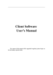
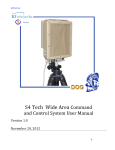
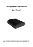
H.264 Wifi IP Cam Tissue Box Covert DVR Camera Wifi IP Camera is Accessible from Anywere in the World by Internet TBX-DVRWF * COLOR 1/3” CCD 540 TVL High Resolution * Sending Live Video and Audio wirelessly by Wi-Fi / 3G Phone / Ethernet * H.264 Algorithm hardware compression * Easy Recording setup by Internet * Super Low Lux Night Vision 0.001Lux * Wide Angle 2.5mm Mini Lens * Real-time Recording D1 640X480 * Rechargeable Li-lon Battery Pack 94h Audio Video Transmitting by Wi-Fi WiFi Router Internet Audio Video Transmitting by Internet Ethernet WiFi Router MODEL TYPE PICK-UP DEVICE HORIZONTAL RESOLUTION MINI ILLUMINATION LENS VIDEO OUTPUT Video Resolution Video Frame Rate Audio Input Audio Compression Audio Output Supported Protocols System Interface CCD Camera Ethernet Internet TBX-DVRWF Tissue Box covert DVR Camera 1/3" COLOR CCD 540TVL 0.001 LUX Slow Shutter Super Wide Angle 2.5mm Lens 1Vp-p, 75 Ohms PAL:352*288(CIF),704*288(2CIF),704*576(D1); NTSC:352*240(CIF),704*240(2CIF),704*480(D1) PAL: 1-25frames/second NTSC:1-30frames/second 1channel G.726 1channel,Unbalanced, 1.4Vp-p, 1Vrms HTTP, SMTP, PPPoE, DDNS, DNS, DHCP, UPnP(CP for NAT) 10M/100M self-adapting Ethernet port, SD card slot WiFi port,802.11b/g wireless network (optional) Alarm Input Alarm Output POWER SUPPLY 1 channel on/off input 1 channel on/off output POWER CONSUMPTION 500mA (-/+10%) DC 12V (-/+10%) * Specifications are subject to change without notice ** Designed in U.S.A. Table of Contents 1 Brief Introduction...........................................................................................................................1 2 Installation Guide...........................................................................................................................1 3 Software Instructions .....................................................................................................................4 3.1 Main Interface .....................................................................................................................4 3.2 The main interface function ................................................................................................7 3.2.1 Toolbar .....................................................................................................................7 3.2.1.1 Image Quality................................................................................................7 3.2.1.2 OSD...............................................................................................................8 3.2.1.3 Sheltered Area ...............................................................................................9 3.2.1.4 Motion Detection ..........................................................................................9 3.2.2 PTZ Control ...........................................................................................................10 3.2.3 Device List .............................................................................................................12 3.2.4 Interface Structure ..................................................................................................12 3.2.5 Other Function .......................................................................................................12 3.2.5.1 Screen Switch..............................................................................................12 3.2.5.2 Client_side Setup ........................................................................................13 3.2.5.3 Playback ......................................................................................................15 3.2.5.4 Language Version........................................................................................16 3.2.5.5 Full Screen ..................................................................................................16 3.3 Device property.................................................................................................................17 3.3.1 Address/Port ...........................................................................................................17 3.3.2 DDNS.....................................................................................................................18 3.3.3 PPPoE.....................................................................................................................19 3.3.4 Multicast.................................................................................................................20 3.3.5 E-Mail ....................................................................................................................21 3.3.6 Date/Time...............................................................................................................22 3.3.7 Alarm In .................................................................................................................23 3.3.8 Alarm Out...............................................................................................................24 3.3.9 PTZ ........................................................................................................................25 3.3.10 Video Channel......................................................................................................26 3.3.11 Audio Channel......................................................................................................27 3.3.12 User ......................................................................................................................28 3.3.13 Update ..................................................................................................................29 3.3.14 Record ..................................................................................................................30 3.3.15 Wireless NIC ........................................................................................................31 3.3.16 Miscellaneous(UPnP function) .......................................................................32 4 Other ............................................................................................................................................33 4.1 LAN and WAN configuration ...........................................................................................33 4.2 Application for DDNS ......................................................................................................33 4.3 Router configuration .........................................................................................................33 Appendix A IE mode....................................................................................................................34 1 Brief Introduction The software used to realize the central control for all internet video monitor devices (including:DVS and IP camera) : monitor, data storage, data transfer\manage\control. This version support 1/4/6/8/9//12/16//20/25/30 display, OSD setting, talkback, record playback, alarm control and MD, etc. The interface is friendly and easy, can help to control more than one device in same time. The main functions below: z Realtime monitor, support CIF/QCIF/Half-D1/D1 format z Support talkback function z Support ptz function, allow Pelco D/P and other transparent protocol z Support alarm /MD/time/ manual trigger record z Support MD(area/sensitivity optional)/private mask/picture snap z Support SMTP, send picture to mailbox when alarm z Support DDNS/PPPoE/DHCP z Support UPnP,auto configuration port z Support long distance online upgrade 2 Installation Guide System requirement z Operating System: Windows 2000/XP/Vista z Processor: Intel Pentium III, 1G or Higher (Pentium IV, 2G or Higher recommended) z RAM: 256 MB or more z Color Monitor: At least DirectX 8.1 or higher and 32M Display storage z HD: More than 40G Software installation Run the client software DVS_Client_Setup.exe, the window below will pop up: 1 Select English, and click【OK】: Click 【Next】, the window below will pop up: Press 【Browse…】 to change the default path. If you do not want to change, press 【Install】. 2 The below window will pop up: Then the setup is completed successfully. 3 3 Software Instructions 3.1 Main Interface Run DVS Client software, need input password, default is blank. Please refer 【Client Setup】 → 【local user management】for user name and password change. The interface as below: For the first login, user need add the IP address/domain name in order to trigger the monitor screen, the steps are as follows: ① Click on the right side, pop following dialog: 4 Mark1: If device not in same network segment, the software can search the IP address but can’t link. Please change device and pc in same segment. Mark2: Default IP is 192.168.0.233, gateway is 192.168.0.1. ② Can add device IP address/ Domain name by manual, click【add】 pop following dialog: ③ Input device IP/domain name, eg input IP/Host testdvs.3322.org, port 8001, device type “DVS/IP-CAM”,click 【OK】 pop following dialog: 5 ④ Choose the right device, input user name and password, default is admin, as following: ⑤ Click 【Connect】, the right column will display the device address, choose “channel 1”, hold the left button, drag it to the need window, as following: 6 3.2 The main interface function 3.2.1 Toolbar Followed by login info, talk, sound, snap, record, color, setup, rotation, play. :Click to check device user number / : Click for Talk off/on / : Click for Sound off/on :Click for current channel snap / : Click to start or off record. Click Click for record path setting, for record playback :Click for brightness/contrast/Saturation/color setting. Default 128 , range is 0-255 / : Click for current screen off/on :Click for screen rotation :Click for image quality/OSD/screen mask/MD setting 3.2.1.1 Image Quality Allow setting frame mode,stream type,frame rate,I frame interval,see below: 【Coding Style】Qualith priority or speed priority 【Coding Rate】 Fixed or dynamic. Fixed on suitable for fixed bandwidth.Dynamic suitable for record. Default dynamic stream, limits on 100Kbps. 【Frame/second】 Range is 1~25,default 10 Fps. 【Gap betweem I-frames】One I frame in per 100 frame, default 300. 7 3.2.1.2 OSD OSD is “on screen display”, mean the info accompany with the image. Allow setting channel info, time, text color and position. 8 3.2.1.3 Sheltered Area Sheltered Area as needed. Hold 【ctrl】 to drag mouse choose the area, click 【clear】 to delete it. The mask effect as below: 3.2.1.4 Motion Detection 【Area setting】Hold 【ctrl】 choose the area, max 4 zones allowed. 【Sensitivity】Setting high for high sensitivity. 【Valid Period of Time】Setting MD valid period and alarm valid period. 【Action】Buzz, notify client,send e-mail. 【Output to】Choose the display channel. 9 3.2.2 PTZ Control Click Click adjust aperture Click adjust lens Click up/down/left/right control pan&tliti or hold mouse left key adjust direction by adjust focus drag the middle dot Preset :choose preset from drop down list can control pt to the setting position. Click the mouse right key then choose 【set current view as a preset point】for preset . Cruise :Click setting the route or choose the already one by drop down list, click 10 to stop the cruise. Click the mouse right key then choose 【set current view as a preset point】,pop following dialog: Click , set your cruise route in the following dialog: 11 3.2.3 Device List Display connected devices name, domain name, channel name ,etc. Click device. Click to pop device property dialog. Click to add connect or disconnect device. 3.2.4 Interface Structure Click following button can adjust your own display mode. Click click save or delete. Click switch display mode, 1/4/6/8/9//12/16//20/25/30 optional 3.2.5 Other Function 3.2.5.1 Screen Switch Click to start or stop screen switch ( mean the switch is in process). 12 3.2.5.2 Client_side Setup Client Setup Click to setup record path/alarm trigger record period/sound/last time scene. More than one path can be saved, the top one will be the default record path. Record up limit 1024M/7200s Video Switch Setting It will realize multi-device or different channels switch in one screen. Click 【page】 arrow to add/delete page, click【stay】arrow to add/delete standstill period, click【 】 choose display mode, hold mouse left key drag the wanted channel to the right column or delete it by double click the channel name. 13 Local User Management Default password is blank. After login, allow add new user and related password/private. Password will be needed when quit under 【Full Screen】. 14 Automatic_Record Allow time record channel/period setting, save path setting in【client setup】. The interface indicator will blink after start this function. 3.2.5.3 Playback Click pop following dialog, Search need file through catalog or event list. Double click to play the file. 15 Please choose device IP under 【Device-side File】then click【Find】when check file in SD card. Mark1:Event mean trigger MD or alarm, event record mean MD or alarm trigger record. Mark2:Device port file mean file save in linked SD card. 3.2.5.4 Language Version The software support Chinese and English, click pop to switch. 3.2.5.5 Full Screen Click change to full screen mode, all action will be locked under this mode, input administrator password when quit. Click the right button to pop: Choose to pop alarm info 16 3.3 Device property Click or choose IP address in device list, click 【Property】 by right key to pop dialog, setup or adjust IP address、DDN、PPPoE、broadcast configuration、user management、 update online,etc. 3.3.1 Address/Port Default IP address:192.168.0.233, subnet mask:255.255.255.0,gateway:192.168.0.1, service port 8001. After change, system will register you restart your device to valid the setup. Change service name not need restart. Mark1: IP address will valid only after device restart. Mark2: When link 2 or more devices, need change related IP address and physical address. 17 Mark3: Outer net visit need mapping the service port, refer router configuration part. DNS server needs change to current DNS IP address also. 3.3.2 DDNS DDNS mean dynamic DNS, for unfixed IP domain name mapping. This client software support peanut shell、3322 and our company DDNS service. Just apply your domain name in the proper network station(refer to Part3.2) then click 【OK】 in the pop dialog, the DDNS will valid. 【DDNS Service Provider】now support www.oray.net and www.3322.org. 【User Name】One account can apply different domain name, the provider request not same. 【Password】The related password when you apply the domain name. 【Dynamic Domain Name】According to domain integrated address. 18 3.3.3 PPPoE The client software allow PPPoE . Link the device to phone line through modem, dial to internet. User can visit the monitor picture by internet from long distance. Choose PPPoE in following dialog then input user name and password then click 【OK】. 19 3.3.4 Multicast Use set device as needed to realize the multicast function. 20 3.3.5 E-Mail When choose mail service, the device will send event report and picture to the appointed mailbox when alarm or MD triggered. 【SMTP Server】Follow your mailbox hints for related setup. 【SMTP Port】default 25. 【 Sender’s Account 】 Need according to the SMTP service if your mailbox support. 【User Account】auto catch account info. 【Password】Account related password. 【Receiver’s Account】Any mailbox which can receive mail. Click【Send A Test Mail】after setup to confirm your action. Mark: For outlook or foxmail user, need set the sender account to valid the function. 21 3.3.6 Date/Time Adjust device date, time. Click【Same with PC】to synchronous with pc. 22 3.3.7 Alarm In 【channel】Allow setup name for choosed channel. 【Actions take to response to alarm】Sound alarm, notice client , send e-mail. 【Output to 】Setup output channel. 【PTZ linkage】Seperate、preset、cruise. Moniter channel must be appointed when choose preset or cruise mode. 【Valid period of time】 Setup alarm input time period. + mean valid period,mean except the period. Mark: The record in SD card will lead the real record time add 0-20s base the setting. 23 3.3.8 Alarm Out 【channel】Allow setup name for choosed channel 【Valid period of time】Setup alarm output time period. + mean valid period,mean except the period 24 3.3.9 PTZ 【Video Channel】choose video channel. 【Address】Matching the PTZ address with protocol. 【Protocol】Support Palco-D & Palco-P, default is Palco-D. 【Step Length】 Range 1~64, default 32. High speed will make the control hard , suggest under 32 for high speed dome. 【Comm Setting】 Set baud rate, data bit, stop bit, parity bit. 25 3.3.10 Video Channel 【Channel】Choose the channel no. 【Name】Setup channel name. 【Resolution】QCIF / CIF / Half_D1 / D1. 【PAL/NTSC】Choose PAL or NTSC. Mark1: Need restart device to valid new setup. Mark2: 4 channel DVS only support channel 1 set as D1 format. 26 3.3.11 Audio Channel 【Channel Number】Choose the channel no. 【Bits Width】8bits / 16bits / 32bits optional. 【Sampling Rate 】The effect will better with frequency increase. 【Compression】Choose different mode to compress audio steam( about 10 tims). Mark: Suggest keep the default setting in normal. Just click open talk back function. 27 3.3.12 User User management is use to add, delete or modify user name and password, and setup corresponding authority. User name can only be English character or number,Chinese is no supported, maximum length of user name or password is 10 characters. User is separated into three classes: ◆ Normal User: Admit to brown monitor image, no authority to setup device and manage user. ◆ Power User: Admit to setup device, no authority to manage user ◆ Administrator: Authorized to setup device and manage user. The default administrator id is admin, password is admin, the id is no allowed to delete. 28 3.3.13 Update User can update device local by client or long distance through IE. Device will auto restart after upgrade. User can check current version no. here. 【Current version 】Display current version, not allow edit. 【File to upload】 Click【Open】find the file then click【Upload】, the following dialog will show the progress. The device will auto restart after upgrade, not shut off during the process. Mark: Online upgrade file DAT is pk2. Firmware program and client program can be upgrade integrated or separated. 29 3.3.14 Record The record property will auto display when link to SD card. In other condition, please click 【IP】→【Property】→【Record】to pop the dialog: Set file limit, 0 mean no limit Valid record period Mark1: Please cut off device before plug SD card. Mark2: Choose FAT32 type when format SD card. Mark3: Click choose 【Device-Side File】 to review record, see diagrammatic presentation: 30 3.3.15 Wireless NIC Wireless network card property will auto display; in other condition click 【IP】→【Property】 →【Record】 to pop the dialog: 31 3.3.16 Miscellaneous(UPnP function) UPnP( Universal Plug and Play), the router will auto mapping TCP and UDP port. Mark1: Router must support UPnP function Mark2: Recommend external port between 1025-32767 32 4 Other 4.1 LAN and WAN configuration ♦ LAN automatically search Run DVS Client, Click , the video server in the local LAN will appear in the device list. Only PC and video server in same network segment can connect. If there are no device in the device list, make sure the following question: ① If DVS is already powered? ② If DVS and PC have been normal connected? If yes, the light will be long bright or flashing. ③ If PC has firewall working? If yes, should do it again after closing the firewall. ♦ WAN manually search If users want to login in another subnet, the device can not automatically be searched. The video device should be manually added as the following steps: ① Register DDNS services from a DDNS service provider. After applications a domain name will be assigned, and an account number and password will be obtained. ② Click mouse right key in device list up item, choose 【Property】→【DDNS】 set your domain info ,please see 3.3.2 for details. ③ When Internet IP is changed. The device will automatically tell DDNS server its new Internet IP. ④ Users only input domain in the network browser can run Client. 4.2 Application for DDNS Normally users use dynamic IP address in the internet. User can use a static hostname instead of a dynamic IP address to monitor Lan device image. In this way, user should register a domain name and obtain a password. The device supports www.3322.org and www.dyndns.org , users can login it and register the domain, after doing it, set your domain info as 3.3.2 for details. 4.3 Router configuration Routers must be set to enable a PC TCP connecting to the device. Routers use port number to decide which device request is allowed, this function is port transmitting or virtual services. 33 Appendix A IE mode When first visit device through IE, user need add http:// by manual to pop the following dialog: Click【 】 download the client and control , then install it. Then input user name and password (default is admin ) can get monitor page, see below: 34