1
EJ1
Modular Temperature
Controllers
User's Manual
Cat. No. H142-E1-04
EJ1
Modular Temperature Controllers
User’s Manual
Revised February 2010
iv
Preface
This manual describes the EJ1 Modular Temperature Controllers, including information on functions,
performances, and application methods.
Observe the following precautions when using an EJ1 Modular Temperature Controller.
• Do not allow the Temperature Controller to be handled by anyone except
a specialist with sufficient knowledge of electrical systems.
• Read this manual thoroughly and be sure you understand it before
attempting to use the Temperature Controller and use the Temperature
Controller correctly according to the information provided.
• Keep this manual in a safe place for easy reference.
Visual Aids
The following headings appear in the left column of the manual to help you locate different types of
information.
Note Indicates information of particular interest for efficient and convenient operation of the product.
1,2,3...
1. Indicates lists of one sort or another, such as procedures, checklists, etc.
OMRON, 2006
All rights reserved. No part of this publication may be reproduced, stored in a retrieval system, or transmitted, in any form, or
by any means, mechanical, electronic, photocopying, recording, or otherwise, without the prior written permission of
OMRON.
No patent liability is assumed with respect to the use of the information contained herein. Moreover, because OMRON is constantly striving to improve its high-quality products, the information contained in this manual is subject to change without
notice. Every precaution has been taken in the preparation of this manual. Nevertheless, OMRON assumes no responsibility
for errors or omissions. Neither is any liability assumed for damages resulting from the use of the information contained in
this publication.
v
Read and Understand this Manual
Please read and understand this manual before using the product. Please consult your OMRON
representative if you have any questions or comments.
Warranty and Limitations of Liability
WARRANTY
OMRON's exclusive warranty is that the products are free from defects in materials and workmanship for a
period of one year (or other period if specified) from date of sale by OMRON.
OMRON MAKES NO WARRANTY OR REPRESENTATION, EXPRESS OR IMPLIED, REGARDING NONINFRINGEMENT, MERCHANTABILITY, OR FITNESS FOR PARTICULAR PURPOSE OF THE PRODUCTS. ANY
BUYER OR USER ACKNOWLEDGES THAT THE BUYER OR USER ALONE HAS DETERMINED THAT THE
PRODUCTS WILL SUITABLY MEET THE REQUIREMENTS OF THEIR INTENDED USE. OMRON DISCLAIMS ALL
OTHER WARRANTIES, EXPRESS OR IMPLIED.
LIMITATIONS OF LIABILITY
OMRON SHALL NOT BE RESPONSIBLE FOR SPECIAL, INDIRECT, OR CONSEQUENTIAL DAMAGES,
LOSS OF PROFITS OR COMMERCIAL LOSS IN ANY WAY CONNECTED WITH THE PRODUCTS,
WHETHER SUCH CLAIM IS BASED ON CONTRACT, WARRANTY, NEGLIGENCE, OR STRICT
LIABILITY.
In no event shall the responsibility of OMRON for any act exceed the individual price of the product on which
liability is asserted.
IN NO EVENT SHALL OMRON BE RESPONSIBLE FOR WARRANTY, REPAIR, OR OTHER CLAIMS
REGARDING THE PRODUCTS UNLESS OMRON'S ANALYSIS CONFIRMS THAT THE PRODUCTS
WERE PROPERLY HANDLED, STORED, INSTALLED, AND MAINTAINED AND NOT SUBJECT TO
CONTAMINATION, ABUSE, MISUSE, OR INAPPROPRIATE MODIFICATION OR REPAIR.
Application Considerations
SUITABILITY FOR USE
OMRON shall not be responsible for conformity with any standards, codes, or regulations that apply to the
combination of products in the customer's application or use of the products.
At the customer's request, OMRON will provide applicable third party certification documents identifying
ratings and limitations of use that apply to the products. This information by itself is not sufficient for a
complete determination of the suitability of the products in combination with the end product, machine,
system, or other application or use.
The following are some examples of applications for which particular attention must be given. This is not
intended to be an exhaustive list of all possible uses of the products, nor is it intended to imply that the uses
listed may be suitable for the products:
• Outdoor use, uses involving potential chemical contamination or electrical interference, or conditions or
uses not described in this manual.
• Nuclear energy control systems, combustion systems, railroad systems, aviation systems, medical
equipment, amusement machines, vehicles, safety equipment, and installations subject to separate
industry or government regulations.
• Systems, machines, and equipment that could present a risk to life or property.
Please know and observe all prohibitions of use applicable to the products.
NEVER USE THE PRODUCTS FOR AN APPLICATION INVOLVING SERIOUS RISK TO LIFE OR
PROPERTY WITHOUT ENSURING THAT THE SYSTEM AS A WHOLE HAS BEEN DESIGNED TO
ADDRESS THE RISKS, AND THAT THE OMRON PRODUCTS ARE PROPERLY RATED AND INSTALLED
FOR THE INTENDED USE WITHIN THE OVERALL EQUIPMENT OR SYSTEM.
PROGRAMMABLE PRODUCTS
OMRON shall not be responsible for the user's programming of a programmable product, or any
consequence thereof.
vi
Disclaimers
CHANGE IN SPECIFICATIONS
Product specifications and accessories may be changed at any time based on improvements and other
reasons.
It is our practice to change model numbers when published ratings or features are changed, or when
significant construction changes are made. However, some specifications of the products may be changed
without any notice. When in doubt, special model numbers may be assigned to fix or establish key
specifications for your application on your request. Please consult with your OMRON representative at any
time to confirm actual specifications of purchased products.
DIMENSIONS AND WEIGHTS
Dimensions and weights are nominal and are not to be used for manufacturing purposes, even when
tolerances are shown.
PERFORMANCE DATA
Performance data given in this manual is provided as a guide for the user in determining suitability and does
not constitute a warranty. It may represent the result of OMRON's test conditions, and the users must
correlate it to actual application requirements. Actual performance is subject to the OMRON Warranty and
Limitations of Liability.
ERRORS AND OMISSIONS
The information in this document has been carefully checked and is believed to be accurate; however, no
responsibility is assumed for clerical, typographical, or proofreading errors, or omissions.
vii
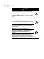
Safety Precautions
■ Definition of Precautionary Information
The following notation is used in this manual to provide precautions required
to ensure safe usage of the product.
The safety precautions that are provided are extremely important to safety.
Always read and heed the information provided in all safety precautions.
The following notation is used.
CAUTION
Indicates a potentially hazardous situation which, if not
avoided, is likely to result in minor or moderate injury or in
property damage.
■ Symbols
Symbol
Meaning
General Caution
Indicates non-specific general cautions, warnings, and
dangers.
Caution
Electrical Shock Caution
Indicates possibility of electric shock under specific
conditions.
viii
Prohibition
General Prohibition
Indicates non-specific general prohibitions.
Mandatory
Caution
General Caution
Indicates non-specific general cautions, warnings, and
dangers.
■ Safety Precautions
CAUTION
Do not touch the terminals while power is being supplied. Doing
so may occasionally result in minor injury due to electric shock.
Use a power supply that complies with the reinforced insulation
specified in IEC 60664 for the EJ1 external power supply or the
power supply connected to the EJ1. If non-compliant power
supplies are used, electric shock may occasionally result in minor
injury.
Do not allow pieces of metal, wire clippings, or fine metallic shavings or filings from installation to enter the product. Doing so may
occasionally result in electric shock, fire, or malfunction.
Do not use the product where subject to flammable or explosive
gas. Otherwise, minor injury from explosion may occasionally
occur.
Never disassemble, modify, or repair the product or touch any of
the internal parts. Minor electric shock, fire, or malfunction may
occasionally occur.
Tighten the terminal screws to between 0.40 and
0.56 N·m. Loose screws may occasionally result in fire.
Set the parameters of the product so that they are suitable for the
system being controlled. If they are not suitable, unexpected
operation may occasionally result in property damage or
accidents.
A malfunction in the product may occasionally make control
operations impossible or prevent alarm outputs, resulting in
property damage. To maintain safety in the event of malfunction of
the product, take appropriate safety measures, such as installing
a monitoring device on a separate line.
ix
Precautions for Safe Use
Be sure to observe the following precautions to prevent operation failure, malfunction, or adverse affects on
the performance and functions of the product. Not doing so may occasionally result in unexpected events.
1) The product is designed for indoor use only. Do not use the product outdoors or in any of the following
locations.
• Places directly subject to heat radiated from heating equipment
• Places subject to splashing liquid or oil atmosphere
• Places subject to direct sunlight
• Places subject to dust or corrosive gas (in particular, sulfide gas or ammonia gas)
• Places subject to intense temperature change
• Places subject to icing or condensation
• Places subject to vibration or strong shocks
2) Use and store the product within the rated ambient temperature and humidity ranges.
Mounting two or more Temperature Controllers side by side, or mounting Temperature Controllers above
each other may cause heat to build up inside the Temperature Controllers, which will shorten their service
life. If the Temperature Controllers are mounted above each other or side by side, use forced cooling by
fans or other means of air ventilation to cool down the Temperature Controllers.
3) To allow heat to escape, do not block the area around the product. Do not block the ventilation holes on
the product.
4) Be sure to wire properly with correct polarity of terminals.
5) Use specified size (M3, width 5.8 mm or less) crimped terminals for wiring. Use a gage of AWG22 to
AWG14 (equal to cross-sectional area of 0.326 to 2.081 mm 2 ) for power supply lines and a gage of
AWG28 to AWG16 (equal to cross-sectional area of 0.081 to 1.309 mm2) for all other lines. (The stripping
length is 6 to 8 mm.) Up to two wires of same size and type, or two crimped terminals can be inserted into
a single terminal.
6) Do not wire terminals that do not have an identified use.
7) To reduce inductive noise, keep the wiring for the product's terminal block away from power cables
carrying high voltages or large currents. Also, do not wire power lines together with or parallel to product
wiring. Using shielded cables and using separate conduits or ducts is recommended.
Attach a surge suppressor or noise filter to peripheral devices that generate noise (in particular, motors,
transformers, solenoids, magnetic coils or other equipment that have an inductance component).
When a noise filter is used at the power supply, first check the voltage or current, and attach the noise
filter as close as possible to the product.
Allow as much space as possible between the product and devices that generate powerful high
frequencies (high-frequency welders, high-frequency sewing machines, etc.) or surge.
8) Use the product within the rated load and power supply.
9) Make sure that the rated voltage is attained within two seconds of turning ON the power using a switch or
relay contact. If the voltage is applied gradually, the power may not be reset or output malfunctions may
occur.
10) Make sure that the product has 30 minutes or more to warm up after turning ON the power before starting
actual control operations to ensure the correct temperature display.
11) The switch or circuit breaker must be within easy reach of the operator, and must be marked as a
disconnecting means for this unit.
12) Do not use paint thinner or similar chemical to clean with. Use standard grade alcohol.
13) Design the system (e.g., the control panel) allowing leeway for the delay required before product outputs
are valid after turning ON power to the product.
14) Never touch the electronic components, connectors, or patterns on product boards with your bare hands.
Always hold the product by the case. Inappropriately handling the product may occasionally damage
internal components due to static electricity.
x
15) Use a switch, relay, or other device with contacts to turn OFF the power supply quickly. Gradually lowering
the voltage of the power supply may result in incorrect outputs or memory errors.
16) Do not touch the electronic components with your hands or subject them to shock when removing the
terminal block.
17) Connect only the specified number of products in only a specified configuration.
18) Mount the product to a DIN Rail mounted vertically to the ground.
19) Always turn OFF the power supply before wiring the product, replacing the product, or changing the
product configuration.
20) Attach the enclosed cover seal to the connector opening on the left end Unit during installation.
21) Do not use port B on the End Unit when using port C on the HFU.
xi
Precautions for Correct Use
● Installation
1)
2)
3)
4)
5)
6)
Do not connect an End Unit directly to an HFU.
Always connect an End Unit to the right side of the Basic Units.
Always connect the HFU to the left side of the Basic Units.
The EJ1 cannot be used linked to a CJ-series PLC.
Use the EJ1G-@@ for gradient temperature control. Use the EJ1N-@@ for any other type of temperature
control.
When removing the terminal block to replace the Unit, be sure to confirm that the new Unit is the same as
the Unit that is being replaced.
● Service Life
1)
2)
3)
Use the product within the following temperature and humidity ranges.
Temperature: −10 to 55°C (with no icing or condensation)
Humidity: 25% to 85%
When the Temperature Controller is incorporated in a control panel, make sure that the controller’s
ambient temperature and not the panel’s ambient temperature does not exceed 55°C.
The service life of electronic devices like the Temperature Controller is determined by the service life of
internal electronic components. Component service life is affected by the ambient temperature: the higher
the temperature, the shorter the service life and the lower the temperature, the longer the service life.
Therefore, the service life can be extended by lowering the temperature of the Temperature Controller.
Mounting two or more Temperature Controllers side by side, or mounting Temperature Controllers above
each other may cause heat to build up inside the Temperature Controllers, which will shorten their service
life. If the Temperature Controllers are mounted above each other or side by side, use forced cooling by
fans or other means of air ventilation to cool down the Temperature Controllers. However, be sure not to
cool only the terminals. Doing so will result in measurement errors.
● Ensuring Measurement Accuracy
1)
2)
3)
4)
When extending or connecting the thermocouple lead wire, be sure to use compensating wires that match
the thermocouple types.
When extending or connecting the lead wire of the platinum resistance thermometer, be sure to use wires
that have low resistance and keep the resistance of the three lead wires the same.
Mount the Temperature Controller so that it is horizontally level.
If the measurement accuracy is low, check to see if input shift has been set correctly.
● Precautions for Operation
1)
2)
3)
xii
It takes a certain amount of time for the outputs to turn ON from after the power supply is turned ON. Due
consideration must be given to this time when designing control panels, etc.
It takes 30 minutes from the time the product is turned ON until the correct temperature is indicated.
Always turn ON the power supply at least 30 minutes before starting temperature control.
Avoid using the Temperature Controller near a radio, television set, or other wireless device. Its use would
result in reception disturbance.
Preparations for Use
Be sure to thoroughly read and understand the manual provided with the product, and check the following points.
Timing
Check point
Purchasing the product Product appearance
Setting the Unit
Wiring
Product model and
specifications
Product installation
location
Terminal wiring
Power supply inputs
Operating environment
Ambient temperature
Vibration and shock
Foreign particles
Details
After purchase, check that the product and packaging are not dented
or otherwise damaged. Damaged internal parts may prevent optimum
control.
Make sure that the purchased product meets the required specifications.
Provide sufficient space around the product for heat dissipation. Do
not block the vents on the product.
Do not subject the terminal screws to excessive stress (force) when
tightening them.
Make sure that there are no loose screws after tightening terminal
screws to the specified torque of 0.40 to 0.56 N·m.
Be sure to confirm the polarity for each terminal before wiring the terminal block and connectors.
Wire the power supply inputs correctly. Incorrect wiring will result in
damage to the internal circuits.
The ambient operating temperature for the product is −10 to 55°C (with
no condensation or icing). To extend the service life of the product,
install it in a location with an ambient temperature as low as possible.
In locations exposed to high temperatures, if necessary, cool the products using a fan or other cooling method.
Check whether the standards related to shock and vibration are satisfied at the installation environment. (Install the product in locations
where the conductors will not be subject to vibration or shock.)
Install the product in a location that is not subject to liquid or foreign
particles entering the product. If sulfide, chlorine, or other corrosive
gases are present, remove the source of the gas, install a fan, or use
other countermeasures to protect the product.
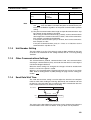
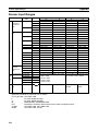
xiii
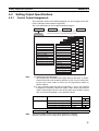
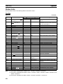
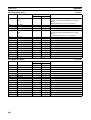
Related Manuals
The manuals related to the EJ1 are configured as shown in the following tables. Refer to these manuals as required.
■ EJ1
Name
EJ1
EJ1N-TC2@
EJ1N-TC4@
EJ1N-HFU@
EJ1C-EDU@
Modular Temperature Controllers User's Manual
CX-Thermo Ver. @ (online help)
EST2-2C-MV@
Cat. No.
Contents
Describes the following information on the EJ1.
H142
(This
• Overview and features
manual) • Basic specifications
• System design
• System configuration
• Mounting and wiring
• Maintenance
• Troubleshooting
--Describes how to set parameters and adjust
(Availdevices (i.e., components such as Temperature
able
Controllers) using the CX-Thermo.
only as
online
help.)
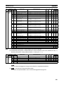
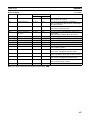
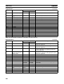
■ CS/CJ-series PLC Manuals
Name
SYSMAC CJ Series
CJ2H-CPU@@-EIP
CPU Unit Hardware Manual
SYSMAC CJ Series
CJ2H-CPU@@-EIP
CPU Unit Software Manual
SYSMAC CJ Series
CJ1G-CPU@@, CJ1M-CPU@@, CJ1G-CPU@@P,
CJ1G/H-CPU@@H, NSJ@-@@@@(B)-G5D,
NSJ@-@@@@(B)-M3D
Programmable Controllers Operation Manual
SYSMAC CS/CJ Series
CS1G/H-CPU@@-EV1, CS1G/H-CPU@@H, CS1DCPU@@H, CS1D-CPU@@S, CJ1G-CPU@@, CJ1MCPU@@, CJ1G-CPU@@P, CJ1G/H-CPU@@H, NSJ@@@@@(B)-G5D, NSJ@-@@@@(B)-M3D
Programmable Controllers Programming Manual
SYSMAC CS/CJ Series
CS1G/H-CPU@@-EV1, CS1G/H-CPU@@H, CS1DCPU@@H, CS1D-CPU@@S, CJ2H-CPU@@-EIP, CJ1GCPU@@, CJ1M-CPU@@, CJ1G-CPU@@P, CJ1G/HCPU@@H, NSJ@-@@@@(B)-G5D, NSJ@-@@@@(B)-M3D
Programmable Controllers Instructions Reference Manual
SYSMAC CS Series
CS1G/H-CPU@@-EV1, CS1G/H-CPU@@H
Programmable Controllers Operation Manual
xiv
Cat. No.
Contents
W472
Provides an outlines of and describes the design,
installation, maintenance, and other basic operations for the CJ-series PLCs.
W473
Describes programming and other methods to use
the functions of the CJ-series PLCs.
W393
Provides an outlines of and describes the design,
installation, maintenance, and other basic operations for the CJ-series PLCs.
W394
Describes programming and other methods to use
the functions of the CS/CJ-series PLCs.
W474
Describes the ladder diagram programming
instructions supported by CS/CJ-series PLCs.
W339
Provides an outlines of and describes the design,
installation, maintenance, and other basic operations for the CS-series PLCs.
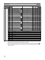
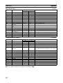
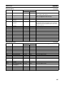
Name
Cat. No.
SYSMAC CS/CJ/NSJ Series
W342
CS1G/H-CPU@@-EV1, CS1G/H-CPU@@H,
CS1D-CPU@@H, CS1D-CPU@@S, CJ1G-CPU@@,
CJ1M-CPU@@, CJ1G-CPU@@P, CJ1G/H-CPU@@H,
CS1W-SCB@@-V1, CS1W-SCU@@-V1,
CJ1W-SCU@@-V1, CP1H-X@@@@-@,
CP1H-XA@@@@-@, CP1H-Y@@@@-@,
Communications Commands Reference Manual
SYSMAC CS/CJ Series
W336
CS1W-SCB@@-V1, CS1W-SCU@@-V1, CJ1W-SCU21@@V1
Serial Communications Boards/Units Operation Manual
Contents
Describes the C-series (Host Link) and FINS communications commands used with CS/CJ-series
PLCs.
Describes the use of Serial Communications Unit
and Boards to perform serial communications with
external devices, including the usage of standard
system protocols for OMRON products.
■ CP-series PLC Manuals
Name
Cat. No.
Contents
CP1H-X40D@-@
W450
Provides the following information on the CP
Series:
CP1H-XA40D@-@
CP1H-Y20DT-D
• Overview, design, installation, maintenance, and
SYSMAC CP Series CP1H CPU Unit Operation Manual
other basic specifications
• Features
• System configuration
• Mounting and wiring
• I/O memory allocation
• Troubleshooting
Use this manual together with the CP1H Programmable Controllers Programming Manual (W451).
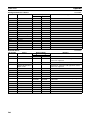
W451
Provides the following information on the CP
CP1H-X40D@-@
Series:
CP1H-XA40D@-@
CP1H-Y20DT-D
• Programming instructions
SYSMAC CP Series CP1H CPU Unit Programming Manual
• Programming methods
• Tasks
• File memory
• Functions
Use this manual together with the CP1H Programmable Controllers Operation Manual (W450).
W462
Provides the following information on the CP
CP1L-L10D@-@
Series:
CP1L-L14D@-@
CP1L-L20D@-@
• Overview, design, installation, maintenance, and
CP1L-M30D@-@
other basic specifications
CP1L-M40D@-@
• Features
CP1L-M60D@-@
• System configuration
SYSMAC CP Series CP1L CPU Unit Operation Manual
• Mounting and wiring
• I/O memory allocation
• Troubleshooting
Use this manual together with the CP1L Programmable Controllers Programming Manual (W451).
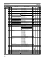
xv
Name
CP1H-X40D@-@
CP1H-XA40D@-@
CP1H-Y20DT-D
CP1L-L10D@-@
CP1L-L14D@-@
CP1L-L20D@-@
CP1L-M30D@-@
CP1L-M40D@-@
CP1L-M60D@-@
SYSMAC CP Series CP1H /CP1L CPU Unit Programming
Manual
CP1L-L10D@-@
CP1L-L14D@-@
CP1L-L20D@-@
CP1L-M30D@-@
CP1L-M40D@-@
CP1L-M60D@-@
SYSMAC CP Series CP1L CPU Unit Introduction Manual
Cat. No.
Contents
W451
Provides the following information on programming
the CP Series:
• Programming methods
• Tasks
• Programming instructions
W461
Describes basic setup methods of CP1L PLCs:
• Basic configuration and component names
• Mounting and wiring
• Programming, data transfer, and debugging
using the CX-Programmer
• Application program examples
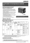
■ G3ZA Multi-channel Power Controller Manual
Name
G3ZA
G3ZA-4H203-FLK-UTU
G3ZA-4H403-FLK-UTU
G3ZA-8H203-FLK-UTU
G3ZA-8H403-FLK-UTU
Multi-channel Power Controller User's Manual
Cat. No.
Contents
Z200
Provides an outline of and describes the features,
installation, wiring, RS-485 serial communications
settings, and basic function for the G3ZA Multichannel Power Controller.
■ G3PW Power Controller Manual
Name
G3PW
G3PW-A220EC-C-FLK
G3PW-A230EC-C-FLK
G3PW-A245EC-C-FLK
G3PW-A260EC-C-FLK
G3PW-A220EC-S-FLK
G3PW-A230EC-S-FLK
G3PW-A245EC-S-FLK
G3PW-A260EC-S-FLK
Power Controller User’s Manual
Cat. No.
Contents
Z280
Provides an outline of and describes the features,
installation, wiring, RS-485 serial communications
settings, and basic function for the G3PW Power
Controller.
■ Programmable Terminal (PT) Manuals
Name
NS-Series
NS5-SQ0@(B)-V1/V2, NS5-TQ0@(B)-V2,
NS5-MQ0@(B)-V2, NS8-TV@@(B)-V1/V2,
NS10-TV0@(B)-V1/V2, NS12-TS0@(B)-V1/V2,
NS5-SQ1@@-V2, NS5-TQ1@@-V2, NS5-MQ1@@-V2
Programmable Terminals Setup Manual
NS-Series
NS5-SQ0@(B)-V1/V2, NS5-TQ0@(B)-V2,
NS5-MQ0@(B)-V2, NS8-TV@@(B)-V1/V2,
NS10-TV0@(B)-V1/V2, NS12-TS0@(B)-V1/V2,
NS5-SQ1@@-V2, NS5-TQ1@@-V2, NS5-MQ1@@-V2
Programmable Terminals Programming Manual
xvi
Cat. No.
V083
V073
Contents
Provides an outline of, and describes the design,
installation, maintenance, and other basic operations for the NS-series PTs. Information is also
included on connecting to hosts and peripheral
devices, and settings required for communications
and PT operation.
Describes the functions of NS-series PTs, including screen configurations, object functions, and
host communications for the PT.
Name
Cat. No.
NSJ-Series
NSJ5-TQ@@(B)-G5D
NSJ5-SQ@@(B)-G5D
NSJ8-TV@@(B)-G5D
NSJ10-TV@@(B)-G5D
NSJ12-TS@@(B)-G5D
NSJ5-TQ@@(B)-M3D
NSJ5-SQ@@(B)-M3D
NSJ8-TV@@(B)-M3D
NSJ Series Operation Manual
W452
NSH Series
NSH5-SQR00B-V2
NSH5-SQG00B-V2
Hand-held Programmable Terminal Operation Manual
V090
(PDF
only)
V086
NS Series
NS-CA002
(PDF
Programmable Terminals RGB and Video Input Unit Opera- only)
tion Manual
Smart Active Parts Reference Manual
V087
(PDF
only)
Contents
Provides the following information about the NSJseries NSJ Controllers:
Overview and features
Designing the system configuration
Installation and wiring
I/O memory allocations
Troubleshooting and maintenance
Use this manual in combination with the following
manuals: SYSMAC CS Series Operation Manual
(W339), SYSMAC CJ Series Operation Manual
(W393), SYSMAC CS/CJ Series Programming
Manual (W394), and NS-V1/-V2 Series Setup
Manual (V083)
Provides an outline of, and describes the design,
installation, maintenance, and other basic operations for the NSH-series NSH5 Hand-held Programmable Terminal. Information is also included
on features, system configuration, wiring, I/O
memory allocations, and troubleshooting.
Describes how to display external video images or
analog RGB imagines on NS-series PTs using a
NS-series RGB and Video Input Unit, including the
following information.
• Features, system configuration, and specifications
• Functions, setting methods, and adjustment
methods
Describes the Smart Active Parts (SAP) functionality and the settings required to use the SAP
library. This document does not describe application restrictions for specific Units or Components
or restrictions in combinations. Always refer to the
operation manual for the products involved before
using the SAP library.
xvii
■ Support Software Manuals
Name
Cat. No.
CXONE-AL@@C-EV3/AL@@D-EV3
W463
CX-One Ver. 3.0 FA Integrated Tool Package Setup Manual
CXONE-AL@@C-EV3/ CXONE-AL@@D-EV3
W464
CX-Integrator Ver. 3.0 Operation Manual
Contents
Installation and overview of CX-One FA Integrated
Tool Package.
Describes operating procedures for the CX-Integrator Network Configuration Tool for CS-, CJ-,
CP-, and NSJ-series Controllers.
Provides information on how to use the CX-Programmer for all functionality except for function
blocks.
Refer to the following manuals when programming:
CJ Series CPU Unit Hardware Manual (Cat. No.
W472) and CJ Series CPU Unit Software Manual
(Cat. No. W473).
CS Series: Operation Manual for Setup (Cat. No.
W339) and Programming Manual for Programmable Controllers (Cat. No. W394)
CJ Series: CJ Series Programmable Controllers
Operation Manual (Cat. No. W393) and Programming Manual for Programmable Controllers (Cat.
No. W394)
SYSMAC WS02-CXPC@-E-V8
CX-Programmer Operation Manual
W446
SYSMAC WS02-CXPC@-E-V8
CX-Programmer Ver. 8.0 Operation Manual
Function Blocks
(CS1G-CPU@@H, CS1H-CPU@@H,
CJ1G-CPU@@H, CJ1H-CPU@@H,
CJ1M-CPU@@, CP1H-X@@@@-@,
CP1H-XA@@@@-@, CP1H-Y@@@@-@
CPU Units)
SYSMAC CX-Designer Ver. 1.0
NS-CXDC1-V1
Operation Manual
NS-Series
NS5-SQ0@(B)-V1/V2
NS5-TQ0@(B)-V2
NS5-MQ0@(B)-V2
NS8-TV@@(B)-V1/V2
NS10-TV0@(B)-V1/V2
NS12-TS0@(B)-V1/V2
NSJ5-TQ@@(B)-G5D
NSJ5-SQ@@(B)-G5D
NSJ8-TV@@(B)-G5D
NSJ10-TV@@(B)-G5D
NSJ12-TS@@(B)-G5D
Ladder Monitor Operation Manual (Ladder Monitor/I/O
Comment Extracting Tool)
W447
Describes the functionality unique to the CX-Programmer Ver. 7.0 and CP-series CPU Units or CS/
CJ-series CPU Units with unit version 3.0 or later
based on function blocks. Functionality that is the
same as that of the CX-Programmer is described
in W446 (enclosed).
V088
Describes how to install and use the CX-Designer,
including screen data creation methods, screen
data transfer methods, and system settings.
Describes the NS-series PT monitoring function
for CS/CJ-series PLC ladder programs, including
the following information.
• Overview and features
• Setup methods
• Basic operations
• Troubleshooting
xviii
V082
Conventions Used in This Manual
Meanings of Abbreviations
The following abbreviations are used in parameter names, figures and in text explanations. These
abbreviations mean the following:
Symbol
TC4/TC2
ch
HFU
EDU
PV
SP
RSP
LSP
LBA
HB
HS
OC
AT
ST
EU
Term
Four-channel and Two-channel Basic Units
Channel
Advanced Unit
End Unit
Process value
Set point
Remote SP
Local SP
Loop burnout alarm
Heater burnout
Heater short
Heater overcurrent
Autotuning
Self-tuning
Engineering unit (See note.)
Note “EU” stands for Engineering Unit. EU is used as the minimum unit for engineering units such as
°C, m, and g. The size of EU varies according to the input type.
For example, when the input temperature setting range is –200 to +1300°C, 1 EU is 1°C, and
when the input temperature setting range is –20.0 to +500.0°C, 1 EU is 0.1°C.
For analog inputs, the size of EU varies according to the decimal point position of the scaling setting, and 1 EU becomes the minimum scaling unit.
xix
xx
TABLE OF CONTENTS
SECTION 1
Outline . . . . . . . . . . . . . . . . . . . . . . . . . . . . . . . . . . . . . . . . . . .
1
1-1
Names of Parts . . . . . . . . . . . . . . . . . . . . . . . . . . . . . . . . . . . . . . . . . . . . . . . . . . . . . . . . . . . .
2
1-2
I/O Configuration and Main Functions . . . . . . . . . . . . . . . . . . . . . . . . . . . . . . . . . . . . . . . . .
5
1-3
Internal Block Diagrams . . . . . . . . . . . . . . . . . . . . . . . . . . . . . . . . . . . . . . . . . . . . . . . . . . . .
9
SECTION 2
Preparations . . . . . . . . . . . . . . . . . . . . . . . . . . . . . . . . . . . . . .
11
2-1
Installation . . . . . . . . . . . . . . . . . . . . . . . . . . . . . . . . . . . . . . . . . . . . . . . . . . . . . . . . . . . . . . .
12
2-2
Wiring Terminals . . . . . . . . . . . . . . . . . . . . . . . . . . . . . . . . . . . . . . . . . . . . . . . . . . . . . . . . . .
16
2-3
Using Tool Ports . . . . . . . . . . . . . . . . . . . . . . . . . . . . . . . . . . . . . . . . . . . . . . . . . . . . . . . . . .
26
2-4
Unit Configuration Examples . . . . . . . . . . . . . . . . . . . . . . . . . . . . . . . . . . . . . . . . . . . . . . . .
27
SECTION 3
Typical Control Examples . . . . . . . . . . . . . . . . . . . . . . . . . . .
33
3-1
Minimum Configuration for Control . . . . . . . . . . . . . . . . . . . . . . . . . . . . . . . . . . . . . . . . . . .
34
3-2
Multi-channel Control . . . . . . . . . . . . . . . . . . . . . . . . . . . . . . . . . . . . . . . . . . . . . . . . . . . . . .
38
3-3
Control Linked to a Host Device . . . . . . . . . . . . . . . . . . . . . . . . . . . . . . . . . . . . . . . . . . . . . .
41
3-4
Controlling G3ZA Controllers Connected to Output Devices . . . . . . . . . . . . . . . . . . . . . . .
45
SECTION 4
Basic Units (TC4 and TC2) Functions . . . . . . . . . . . . . . . . .
49
4-1
Setting Input Specifications . . . . . . . . . . . . . . . . . . . . . . . . . . . . . . . . . . . . . . . . . . . . . . . . . .
51
4-2
Setting Output Specifications . . . . . . . . . . . . . . . . . . . . . . . . . . . . . . . . . . . . . . . . . . . . . . . .
57
4-3
Setting Control Specifications . . . . . . . . . . . . . . . . . . . . . . . . . . . . . . . . . . . . . . . . . . . . . . . .
64
4-4
Setting Alarm Specifications . . . . . . . . . . . . . . . . . . . . . . . . . . . . . . . . . . . . . . . . . . . . . . . . .
86
4-5
Detecting Current Errors . . . . . . . . . . . . . . . . . . . . . . . . . . . . . . . . . . . . . . . . . . . . . . . . . . . .
91
4-6
Using the Loop Break Alarm (LBA) . . . . . . . . . . . . . . . . . . . . . . . . . . . . . . . . . . . . . . . . . . .
102
4-7
Other Functions (TC4 and TC2) . . . . . . . . . . . . . . . . . . . . . . . . . . . . . . . . . . . . . . . . . . . . . .
104
SECTION 5
Advanced Unit (HFU) Functions. . . . . . . . . . . . . . . . . . . . . . 117
5-1
Programless Communications . . . . . . . . . . . . . . . . . . . . . . . . . . . . . . . . . . . . . . . . . . . . . . . .
118
5-2
Connecting More Than One HFU . . . . . . . . . . . . . . . . . . . . . . . . . . . . . . . . . . . . . . . . . . . .
157
5-3
Other HFU Functions . . . . . . . . . . . . . . . . . . . . . . . . . . . . . . . . . . . . . . . . . . . . . . . . . . . . . .
166
SECTION 6
CompoWay/F Communications . . . . . . . . . . . . . . . . . . . . . . 169
6-1
Communications Settings . . . . . . . . . . . . . . . . . . . . . . . . . . . . . . . . . . . . . . . . . . . . . . . . . . .
170
6-2
Frame Configuration . . . . . . . . . . . . . . . . . . . . . . . . . . . . . . . . . . . . . . . . . . . . . . . . . . . . . . .
172
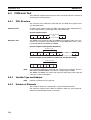
6-3
FINS-mini Text . . . . . . . . . . . . . . . . . . . . . . . . . . . . . . . . . . . . . . . . . . . . . . . . . . . . . . . . . . .
174
6-4
Detailed Description of Services . . . . . . . . . . . . . . . . . . . . . . . . . . . . . . . . . . . . . . . . . . . . . .
176
xxi
TABLE OF CONTENTS
SECTION 7
Modbus Communications . . . . . . . . . . . . . . . . . . . . . . . . . . . 191
7-1
Communications Settings . . . . . . . . . . . . . . . . . . . . . . . . . . . . . . . . . . . . . . . . . . . . . . . . . . .
192
7-2
Frames . . . . . . . . . . . . . . . . . . . . . . . . . . . . . . . . . . . . . . . . . . . . . . . . . . . . . . . . . . . . . . . . . .
194
7-3
Function Codes . . . . . . . . . . . . . . . . . . . . . . . . . . . . . . . . . . . . . . . . . . . . . . . . . . . . . . . . . . .
196
7-4
Variable Areas . . . . . . . . . . . . . . . . . . . . . . . . . . . . . . . . . . . . . . . . . . . . . . . . . . . . . . . . . . . .
197
7-5
Detailed Description of Services . . . . . . . . . . . . . . . . . . . . . . . . . . . . . . . . . . . . . . . . . . . . . .
198
SECTION 8
Errors and Error Processing . . . . . . . . . . . . . . . . . . . . . . . . . 205
8-1
Things to Check First . . . . . . . . . . . . . . . . . . . . . . . . . . . . . . . . . . . . . . . . . . . . . . . . . . . . . .
206
8-2
Determining Errors from Indicators . . . . . . . . . . . . . . . . . . . . . . . . . . . . . . . . . . . . . . . . . . .
207
8-3
Determining the Error from the Status . . . . . . . . . . . . . . . . . . . . . . . . . . . . . . . . . . . . . . . . .
209
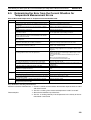
8-4
Determining the Error from the Current Situation for Communications Errors . . . . . . . . . .
214
8-5
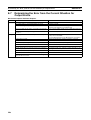
Determining the Error from the Current Situation for Temperature Measurement Errors . .
223
8-6
Determining the Error from the Current Situation for Temperature Control Errors . . . . . . .
224
8-7
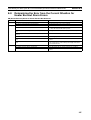
Determining the Error from the Current Situation for Output Errors . . . . . . . . . . . . . . . . . .
226
8-8
Determining the Error from the Current Situation for Heater Burnout Alarm Errors. . . . . .
227
Appendix . . . . . . . . . . . . . . . . . . . . . . . . . . . . . . . . . . . . . . . . . 229
Index. . . . . . . . . . . . . . . . . . . . . . . . . . . . . . . . . . . . . . . . . . . . . 273
Revision History . . . . . . . . . . . . . . . . . . . . . . . . . . . . . . . . . . . 281
xxii
About this Manual:
This manual describes the EJ1 Modular Temperature Controllers and includes the sections described
below. Please read this manual carefully and be sure you understand the information provided before
attempting to set up or operate an EJ1 Modular Temperature Controller.
• Overview
Section 1 Outline describes the features, nomenclature, and functions of the EJ1.
• Setup
Section 2 Preparations describes the preparations required to use the EJ1, including installation, wiring, and switch settings.
• Application Examples
Section 3 Typical Control Examples describes the basic applications of the EJ1 using specific control examples.
• Functions of EJ1 Basic Units (TC4/TC2)
Section 4 Basic Units (TC4 and TC2) Functions describes the functions of EJ1 Basic Units.
• Functions of the EJ1 Advanced Unit (HFU)
Section 5 Advanced Unit (HFU) Functions describes the functions of EJ1 Advanced Unit.
• Operation Using Communications
Section 6 CompoWay/F Communications and Section 7 Modbus Communications describe how
to use communications based on communications commands.
• Troubleshooting
Section 8 Errors and Error Processing describes methods for checking possible problems in operation depending on classifications of Temperature Controller status.
• Specifications and Parameter Lists
Appendix provides specifications, parameter lists, status lists, and other reference information.
!WARNING Failure to read and understand the information provided in this manual may result in personal injury or death, damage to the product, or product failure. Please read each section
in its entirety and be sure you understand the information provided in the section and
related sections before attempting any of the procedures or operations given.
xxiii
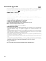
Functional Upgrades
V1.2
The EJ1C-EDUC-NFLK (with connector terminal block) has been added to the End Units (EDU) and
the functions of previous models have been improved. Information in this manual related to improved
functionality is indicated with the V1.2 mark. The improved functionality is outlined below.
• Basic Units (TC4/TC2)
• Autotuning is provided for heating/cooling control.
• Self-tuning has been added.
• A switch can be used to display the output status on the operation indicators during operation.
• Modbus communications can be used to read and write all parameters, and to executed any of the
operation commands.
• A switch setting can be changed to use Modbus communications on port B.
• A switch setting can be used to set the baud rate of port B.
• A C0/80 status has been added for to the variable types.
• Up to eight G3PW Power Controllers can be connected to one Basic Unit.
Note 1. The G3PW can be connected to EJ1 V1.1.
2. The G3PW and G3ZA cannot be used together.
• Advanced Unit (HFU)
• Bit specification operation commands have been added to the parameters that can be specified for
programless download settings. This simplifies the program when operation commands are executed.
• The G3ZA or G3PW Monitor parameter has been added to the parameters that can be specified for
programless upload settings. Up to four G3ZA Multi-channel Power Controllers or up to four G3PW
Power Controllers can be connected to one TC4/ TC2 Unit.
• The maximum number of parameters that can be specified for programless upload/download setting
has been increased from 600 to 1200 each.
• The maximum number of TC4/TC2 Units that an HFU can control has been increased from 16 to 32
Units.
• Communications unit numbers 32 to 39 can be used in the HFU via programless communications.
This allows the communications unit numbers of TC4/TC2 connected to an HFU to be numbered
sequentially, making it easy to copy HFU and TC settings to other HFUs and TCs.
• Support Software
Use version 4.10 or higher of the CX-Thermo when using the upgraded functions.
xxiv
• Identifying Upgraded Models
The new functionality can be used with version 1.2 (V1.2). Check the label on the Temperature Controller or the box to determine the version. Models not marked “Ver. 1.1” are version 1.0.
Temperature Controller Label
Box Label
Version
Version
xxv
Functional Upgrades
V1.1
EJ1 Temperature Controllers with linear outputs (EJ1N-TC2A-CNB and EJ1N-TC2B-CNB) have been
added and the functions of the previous EJ1 Controllers with pulse outputs have been improved. Information in this manual related to improved functionality is indicated with this mark: V1.1 . The improved
functionality is outlined below.
• Basic Units (TC4/TC2)
• Modbus communications can be used on port B.
• Software version 2 of the G3ZA Multi-channel Power Controller can be used.
Note 1. When more than one G3ZA Multi-channel Power Controller is connected, version 1 and version 2 can be mixed. (Up to 8 G3ZA Multi-channel Power Controllers can be connected.)
2. Software version 2 of G3ZA Multi-channel Power Controller can also be used with EJ1 version
1.0.
• Advanced Unit (HFU)
• Programless communications can be used with 1: N connections.
• The maximum number of parameters that can be specified for programless upload/download settings
has been increased from 300 to 600 each.
• Connection is now possible to MELSEC-QnA/An/AnS/FX3uc-series PLCs.
• A new setting read operation has been added to programless communications: Setting Read 2.
• The speed of programless communications has been increased.
• Either “continue” or “stop” can be selected for when errors occur in programless communications.
• Support Software
Use version 3.20 or higher of the CX-Thermo when using the upgraded functions.
• Identifying Upgraded Models
The new functionality can be used with version 1.1 (V1.1). Check the label on the Temperature Controller or the box to determine the version. Models not marked “Ver. 1.1” are version 1.0.
Temperature Controller Label
Box Label
Version
EJ1 ******
TYPE
TEMPERATURE CONTROLLER
MULTI-RANGE
TEMP.
VOLTS
24VDC
V1.1
Ver.
LOT No.
xxvi
****
QTY.
1
Version
SECTION 1
Outline
This section describes the features, nomenclature, and functions of the EJ1.
1-1
1-2
1-3
Names of Parts . . . . . . . . . . . . . . . . . . . . . . . . . . . . . . . . . . . . . . . . . . . . . . . .
2
1-1-1
Appearance . . . . . . . . . . . . . . . . . . . . . . . . . . . . . . . . . . . . . . . . . . . .
2
1-1-2
Names of Parts on Front Panel . . . . . . . . . . . . . . . . . . . . . . . . . . . . .
2
1-1-3
Meanings of Indicators . . . . . . . . . . . . . . . . . . . . . . . . . . . . . . . . . . .
3
1-1-4
Using Setting Switches . . . . . . . . . . . . . . . . . . . . . . . . . . . . . . . . . . .
3
I/O Configuration and Main Functions . . . . . . . . . . . . . . . . . . . . . . . . . . . . . .
5
1-2-1
I/O Configuration . . . . . . . . . . . . . . . . . . . . . . . . . . . . . . . . . . . . . . .
5
1-2-2
Main Unit Functions . . . . . . . . . . . . . . . . . . . . . . . . . . . . . . . . . . . . .
6
1-2-3
Model Number Legend. . . . . . . . . . . . . . . . . . . . . . . . . . . . . . . . . . .
7
Internal Block Diagrams . . . . . . . . . . . . . . . . . . . . . . . . . . . . . . . . . . . . . . . . .
9
1
Section 1-1
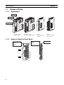
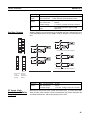
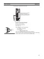
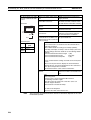
Names of Parts
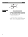
1-1
Names of Parts
1-1-1
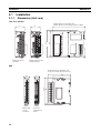
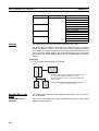
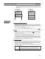
Appearance
Slider
Front panel
Terminal block
TC4, TC2, or HFU
Screw Terminals
1-1-2
TC4, TC2, or HFU
Screw-Less Clamp Terminals
EDUA
Models with Screw
Terminals
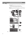
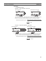
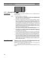
Names of Parts on Front Panel
Operation Indicators
Operation Indicators
Port A connector
COM1
COM2
COM3
PWR 1
RUN 2
ERR 3
ALM 4
SW1
SW2
TC4, TC2, or HFU
2
EDUC
Connector terminal
block model
EDU
Section 1-1
Names of Parts
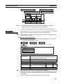
1-1-3
Meanings of Indicators
Operation Indicators
TC4 and TC2
Name
PWR/1 V1.2
RUN/2 V1.2
ERR/3 V1.2
ALM/4 V1.2
COM1
COM2
COM3
Color
Green
Green
Red
Red
Orange
Orange
Orange
Meaning: When SW2 No. 6 is OFF
Meaning: When SW2 No. 6 is ON V1.2
Lights when the power is ON.
Lit when output 1 is ON.
Lights during operation.
Lit when output 2 is ON.
Flashes or lights when an error occurs.
Lit when output 3 is ON.
Lights when an alarm is activated.
Lit when output 4 is ON.
Flashes during communications via port A on the End Unit.
Flashes during communications via port B on the End Unit.
Flashes during communications with the G3ZA.
HFU
Name
PWR
RUN
ERR
ALM
COM1
COM2
COM3
Note
1-1-4
Color
Green
Green
Red
Red
Orange
Orange
Orange
Meaning
Lights when the power is ON. (See note.)
--Flashes or lights when an error occurs.
Lights when an alarm is activated.
Flashes during communications via port A on the End Unit.
Flashes when the EJ1 system is in operation.
Flashes during communications via port C.
Some time is required for the indicators to light after the power is turned ON.
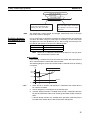
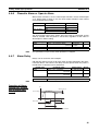
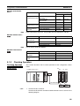
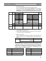
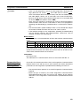
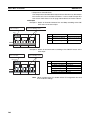
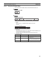
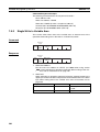
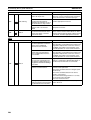
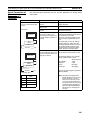
Using Setting Switches
• Check that the EJ1 is turned OFF before operating the switches. The settings are enabled when the power is turned ON.
• Set the switches with a small flat-blade screwdriver. Do not set the
switches midway between settings.
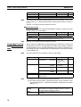
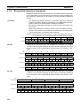
Setting the Unit
Number
SW1 and SW2 are used together to set the unit number to between 00 and
63.
Note
The factory setting is unit number 01.
ON
CD
AB E
5
234 6
F01
1 2 3 4 5 6 7 8
789
SW1
SW2
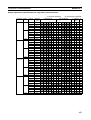
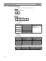
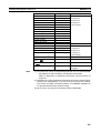
Unit Number Settings
SW2
1
OFF
ON
OFF
ON
2
OFF
OFF
ON
ON
SW1
0
00
16
32
48
1
01
17
33
49
2
02
18
34
50
3
03
19
35
51
4
04
20
36
52
5
05
21
37
53
6
06
22
38
54
7
07
23
39
55
8
08
24
40
56
9
09
25
41
57
A
10
26
42
58
B
11
27
43
59
C
12
28
44
60
D
13
29
45
61
E
14
30
46
62
F
15
31
47
63
3
Section 1-1
Names of Parts
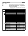
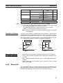
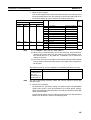
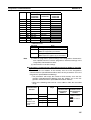
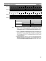
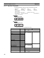
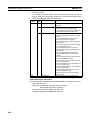
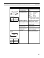
Setting Switch 2
(SW2) Settings
EJ1@-TC Basic Units
SW2
Meaning
3 V1.2
Set to ON when using the Modbus communications protocol for port B.
OFF: The setting for port B communications protocol is used.
ON: Modbus is used.
4 to 5 V1.2 Set the baud rate of port B.
4 = OFF, 5 = OFF: Use the baud rate parameter setting for port B
(default: 9.6 kbps).
4 = ON, 5 = OFF: 19.2 kbps
4 = OFF, 5 = ON: 38.4 kbps
4 = ON, 5 = ON: 115.2 kbps
6 V1.2
Set to ON to display the output status on the operation indicators.
OFF: The operation status is displayed (PWR, RUN, ERR, and ALM).
ON: The output status is displayed (outputs 1, 2, 3, and 4).
Note Normally keep this pin set to OFF so that the operation status
can be checked.
ON: G3ZA Multi-channel Power Controller in operation
ON when using a G3PW Power Controller. V1.1
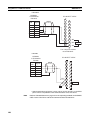
Use when an HFU is used and Units are distributed. (See note.)
7
8
Turn ON pin 8 on SW2.
Note
EDU
TC4/2
Turn ON pin 8 on SW2.
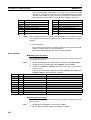
Make sure power to the Unit is turned OFF before changing the setting of any
pin other than pin number 6. Pin number 6 can be turned ON or OFF while the
power is ON.
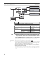
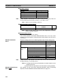
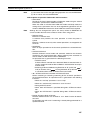
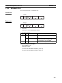
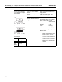
EJ1@-HFU (Advanced
Unit)
SW2
3 to 7
8
4
TC4/2
EDU
TC4/2
TC4/2
EDU
TC4/2
TC4/2
To use an HFU with distributed positioning, turn ON pin number 8 on SW2 on
the TC Unit connected at the left end of the Block.
Refer to SECTION 2 Preparations for information on wiring.
HFU
Note
Meaning
Not used (OFF)
• EJ1@-HFU@-NFLK
OFF: RS-485 is selected.
ON: RS-232C is selected.
• EJ1@-HFU@-NFL2
Not used (OFF).
Section 1-2
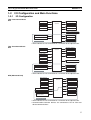
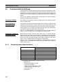
I/O Configuration and Main Functions
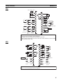
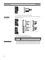
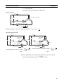
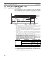
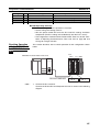
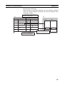
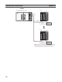
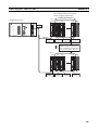
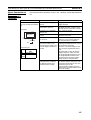
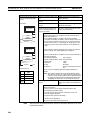
1-2
1-2-1
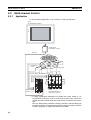
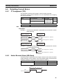
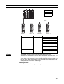
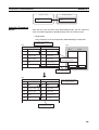
I/O Configuration and Main Functions
I/O Configuration
TC4: Four-channel Basic
Unit
Main input 1
Main input 2
Control
section
Control output 1
Control output 2
Main input 3
Control output 3
Main input 4
Control output 4
G3ZA communications
Port A communications
Internal bus 1
Port B communications
Internal bus 2
Internal bus 3
Inside the device
• Internal device I/O are connected via a connector to the adjacent Unit.
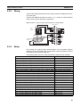
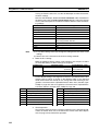
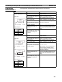
TC2: Two-channel Basic
Unit
Main input 1
Main input 2
Control
section
Control output 1
Control output 2
Control output 3
Event input 1
Control output 4
Event input 2
CT input 1
G3ZA communications
CT input 2
Port A communications
Internal bus 1
Port B communications
Internal bus 2
Internal bus 3
Inside the device
• Internal device I/O are connected via a connector to the adjacent Unit.
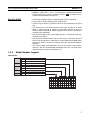
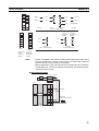
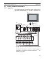
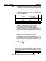
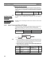
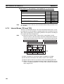
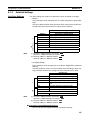
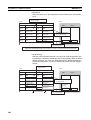
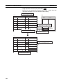
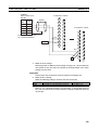
HFU (Advanced Unit)
Event input 1
Event input 2
Control
section
Auxiliary output 1
Auxiliary output 2
Event input 3
Auxiliary output 3
Event input 4
Auxiliary output 4
Port C communications
Internal bus 1
Port A communications
Internal bus 2
Communications
between Units
Internal bus 3
Inside the device
• Internal device I/O are connected via a connector to the adjacent Unit.
• Communications between devices are connected to TC4 or TC2 host
device communications.
5
Section 1-2
I/O Configuration and Main Functions
EDU: End Unit
Adjacent Unit
Port A communications
Port B communications
Auxiliary output 1 (See note.)
Auxiliary output 2 (See note.)
Note
1-2-2
Auxiliary outputs are output via an internal bus.
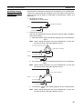
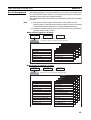
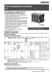
Main Unit Functions
Basic Units (TC4 and
TC2)
• The Basic Units are modular temperature controllers with I/O.
• There are two models of Basic Unit: The TC4 with four I/O channels and
the TC2 with two I/O channels.
• Up to eight G3ZA Multi-channel Power Controllers, or V1.1 G3PW Power
Controllers V1.1 , can be connected to each Basic Unit.
TC4
• One TC4 Unit controls temperature on 4 channels.
• Multi-input is supported for thermocouple, platinum resistance thermometer, or analog input.
• The type of input can be set separately for each channel.
• Control outputs are pulse voltage outputs.
• Both screw terminals and screw-less clamp terminals are available.
• Terminal blocks can be detached and attached.
TC2
• One TC2 Unit controls temperature on 2 channels.
• Multi-input is supported for thermocouple, platinum resistance thermometer, or analog input.
• The type of input can be set separately for each channel.
• Control outputs are pulse voltage outputs or current outputs
• Connect a current transformer (CT) to use the heater burnout and heater
overcurrent alarms.
• There are two event inputs. Any of the following can be used by setting
event input assignments: Run/stop, auto/manual, remote SP/local SP, and
bank switching.
• Both screw terminals and screw-less clamp terminals are available.
• Terminal blocks can be detached and attached.
Advanced Unit (HFU)
• An HFU monitors the Basic Units and collects data.
• Up to sixteen Basic Units, or 32 version V1.2 Units, can be connected to
one HFU.
• Data can be exchanged between the EJ1 and PLCs using programless
communications.
• With version V1.0, up to 300 data items can be read from a PLC to the
EJ1 and up to 300 data items can be written from the EJ1 to a PLC. With
version V1.1 , up to 600 data items can be read from a PLC to the EJ1
and up to 600 data items can be written from the EJ1 to a PLC. With version V1.2 , up to 1,200 data items can be read from a PLC to the EJ1 and
up to 1,200 data items can be written from the EJ1 to a PLC.
6
Section 1-2
I/O Configuration and Main Functions
• OMRON CS/CJ-series PLCs and Mitsubishi Q/QnA/QnAS/An/AnS/
FX3UC-series PLCs can be connected. (Version V1.1 or higher must be
used for An/AnS/FX3UC-series PLCs.
End Unit (EDU)
• The End Unit supplies power to connected Basic Units and HFUs.
• An End Unit is always required when using the EJ1.
• A total of up to 16 HFUs and Basic Units can be connected to one End
Unit.
• The End Unit has two communications ports: port A and port B. Write
Mode is valid for port B. If settings are changed from port A, they are
always written to EEPROM. When using port A, be sure to consider the
write life of the EEPROM.
• Two communications ports are provided for port A: a connector and terminal block connections.
• The connector communications port can be used as a tool port. The End
Unit can be connected to a computer via a special E58-CIFQ1 USB-Serial
Conversion Cable to make EJ1 settings using the CX-Thermo Support
Software.
• The terminal block communications port can be used to wire between
more than one EJ1 for distributed positioning of the EJ1. Up to 64 HFUs
and Basic Units can be connected this way.
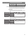
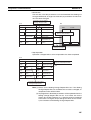
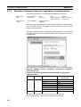
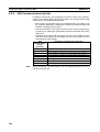
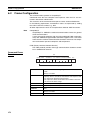
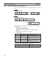
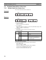
1-2-3
Model Number Legend
TC4 and TC2
Options
None
H
B
Outputs
Q
N
Terminal
type
A
B
Unit name T C 4
Type
2 CT inputs
2 event inputs
2 pulse voltage outputs
2 transistor outputs
Screw terminals
Screw-less clamp terminals
TC2
Four-channel Temperature Control Unit
Two-channel Temperature Control Unit
N
Standard control
1
2
3
4
5
6
7
8
9 10 11 12 13 14
E J
1 N -
T C 4 A -
Q Q
E J
1 N -
T C 4 B -
Q Q
E J
1 N -
T C 2 A -
Q N H B
E J
1 N -
T C 2 B -
Q N H B
E J
1 N -
T C 2 A -
C N B
E J
1 N -
T C 2 B -
C N B
7
Section 1-2
I/O Configuration and Main Functions
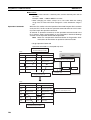
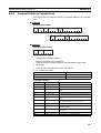
HFU
Communications FLK
FL2
Outputs
Terminal
type
N
A
B
Unit name HFU
Type
N
CompoWay/F (RS-485/RS-232C)
CompoWay/F (RS-422)
4 transistor outputs
Screw terminals
Screw-less clamp terminals
Advanced Unit
Standard control
1
2
3
4
5
6
7
8
9 10 11 12 13 14
E J
1 N -
H F
U A -
N F L
K
E J
1 N -
H F
U A -
N F L
2
E J
1 N -
H F
U B -
N F L
K
E J
1 N -
H F
U B -
N F L
2
6
8
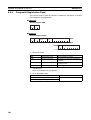
EDU
Communications FLK
CompoWay/F
N
Outputs
Terminal type A
2 transistor outputs
Screw terminals
Connector terminal block model
End Unit
Common model
C
Unit name EDU
Type
C
1
2
E J
E J
8
3
4
5
1 C 1 C -
7
9 10 11 12 13 14
E D U A E D U C -
N F L K
N F L K
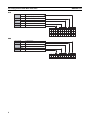
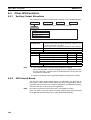
Section 1-3
Internal Block Diagrams
1-3
Internal Block Diagrams
TC4
Switch
inputs
Indicators
EEPROM
Main input 1
Temperature/analog input circuit
Waveform
shaping
circuit
Drive
circuit
Pulse voltage
outputs
Control output 1
Main input 2
Temperature/analog input circuit
Waveform
shaping
circuit
Drive
circuit
Pulse voltage
outputs
Control output 2
Microcomputer
Main input 3
Temperature/analog input circuit
Waveform
shaping
circuit
Drive
circuit
Pulse voltage
outputs
Control output 3
Main input 4
Temperature/analog input circuit
Waveform
shaping
circuit
Drive
circuit
Pulse voltage
outputs
Control output 4
Port B communications circuit
G3ZA communications
G3ZA communications circuit
Connector between Units
Connector between Units
Port A communications circuit
Internal buses 1 to 3
24 VDC
TC2
Switch
inputs
Main input 1
Indicators
EEPROM
Waveform
shaping
circuit
Temperature/analog input circuit
Drive
circuit
Pulse voltage
outputs
Control output 1
(See note.2)
Waveform
shaping
circuit
Temperature/analog input circuit
CT input 1
CT input circuit
Waveform
shaping
circuit
CT input 2
CT input circuit
Waveform
shaping
circuit
(See
note.1)
Event input
circuit
Waveform
shaping
circuit
Event input 2
Event input
circuit
Waveform
shaping
circuit
Connector between Units
Event input 1
Drive
circuit
Pulse voltage
outputs
Control output 2
Drive
circuit
Transistor
outputs
Control output 3
Drive
circuit
Transistor
outputs
Control output 4
Microcomputer
Port A communications circuit
Port B communications circuit
G3ZA communications circuit
Internal buses 1 to 3
24 VDC
G3ZA communications
Connector between Units
Main input 2
: Functional isolation
Note
(1) The CT inputs are not present on EJ1 Controllers with linear outputs.
(2) These are current outputs on EJ1 Controllers with linear outputs.
9
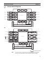
Section 1-3
Internal Block Diagrams
HFU
Switch
inputs
Indicators
EEPROM
Event input 1
Event input
circuit
Waveform
shaping
circuit
Drive
circuit
Transistor
outputs
Auxiliary output 1
Event input 2
Event input
circuit
Waveform
shaping
circuit
Drive
circuit
Transistor
outputs
Auxiliary output 2
Event input 3
Event input
circuit
Waveform
shaping
circuit
Drive
circuit
Transistor
outputs
Auxiliary output 3
Event input 4
Event input
circuit
Waveform
shaping
circuit
Drive
circuit
Transistor
outputs
Auxiliary output 4
SRAM
Port C communications
circuit
Microcomputer
Port B communications circuit
Connector between Units
Connector between Units
Port A communications circuit
Port C communications
Internal buses 1 to 3
24 VDC
EDU
Port A connector
TTL conversion circuit
Port A communications
Connector between Units
Port B communications
Internal bus 1
Internal bus 2
24 VDC
Drive
circuit
Transistor
outputs
Auxiliary output 1
Drive
circuit
Transistor
outputs
Auxiliary output 2
Input power supply
24 VDC
: Functional isolation
10
SECTION 2
Preparations
This section describes the preparations required to use the EJ1, including installation, wiring, and switch settings.
2-1
2-2
2-3
2-4
Installation. . . . . . . . . . . . . . . . . . . . . . . . . . . . . . . . . . . . . . . . . . . . . . . . . . . .
12
2-1-1
Dimensions (Unit: mm) . . . . . . . . . . . . . . . . . . . . . . . . . . . . . . . . . .
12
2-1-2
Mounting and Removing Terminal Blocks. . . . . . . . . . . . . . . . . . . .
13
Wiring Terminals. . . . . . . . . . . . . . . . . . . . . . . . . . . . . . . . . . . . . . . . . . . . . . .
16
2-2-1
Terminal Arrangement . . . . . . . . . . . . . . . . . . . . . . . . . . . . . . . . . . .
16
2-2-2
Wiring Precautions . . . . . . . . . . . . . . . . . . . . . . . . . . . . . . . . . . . . . .
18
2-2-3
Wiring . . . . . . . . . . . . . . . . . . . . . . . . . . . . . . . . . . . . . . . . . . . . . . . .
19
Using Tool Ports . . . . . . . . . . . . . . . . . . . . . . . . . . . . . . . . . . . . . . . . . . . . . . .
26
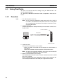
2-3-1
Procedure . . . . . . . . . . . . . . . . . . . . . . . . . . . . . . . . . . . . . . . . . . . . .
26
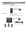
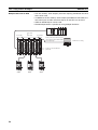
Unit Configuration Examples . . . . . . . . . . . . . . . . . . . . . . . . . . . . . . . . . . . . .
27
2-4-1
29
Connection Precautions . . . . . . . . . . . . . . . . . . . . . . . . . . . . . . . . . .
11
Section 2-1
Installation
2-1
2-1-1
Installation
Dimensions (Unit: mm)
TC4, TC2, and HFU
Models with Screw Terminals: 109
Models with Screw-less Clamp Terminals: 104.85
95.4
Models with Screw
Terminals
90
31
31
Models with Screw-less
Clamp Terminals
EDU
Models with Screw Terminals: 76.2
Connector terminal block model: 79.7
15.7
EDUA
EDUC
60
95.4
90
15.7
Models with
Screw
Terminals
12
Connector
terminal block
model
Section 2-1
Installation
2-1-2
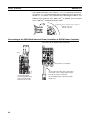
Mounting and Removing Terminal Blocks
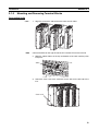
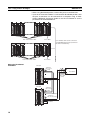
Connecting Units
1,2,3...
Note
1. Align the connectors and connect the Units to each other.
Connect the EDU on the right end of the EJ1 and the HFU on the left end.
2. Slide the yellow sliders on the top and bottom of the Units until they click
into place.
Slider
Lock
3. Attach the cover seal to the connector on the Unit on the left end of the
EJ1.
Cover seal
13
Section 2-1
Installation
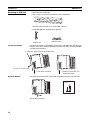
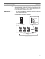
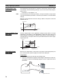
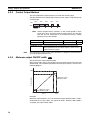
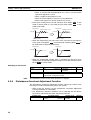
Mounting to DIN Rail
• Mount the EJ1 to DIN Rail.
• Use screws to secure the DIN Rail in at least 3 locations.
DIN Rail: PFP-50N (50 cm) or PFP-100N (100 cm)
• Install the DIN Rail vertically to the ground.
Vertical: OK
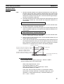
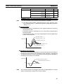
Installation Method
Horizontal: NG
Pull down the hooks on the bottoms of the Units, and then catch the hooks on
the tops of the Units onto the DIN Rail and press the Units onto the DIN Rail
until they lock into place.
2. Catch the upper hooks onto the DIN Rail.
3. Press in on the Units.
1. Pull down the hooks.
Removal Method
4. Make sure the Units are
locked into place.
Pull down on the hooks with a flat-blade screwdriver and lift up on the Units.
Flat-blade screwdriver
14
2.5
0.4
Flat-blade screwdriver
(unit: mm)
Section 2-1
Installation
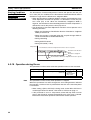
End Plate Installation
Always mount an End Plate on each side of the EJ1.
PFP-M End Plates (2)
PFP-M
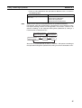
Removing Terminal
Blocks
1,2,3...
1. Pull down the terminal block lever.
Pull down the lever.
2. Pull off the terminal block.
Pull off the terminal block.
Note
Screw and screw-less terminal blocks cannot be exchanged. Use the type of
terminal block supplied with the TC Unit.
15
Section 2-2
Wiring Terminals
2-2
2-2-1
Wiring Terminals
Terminal Arrangement
TC4
Pulse voltage outputs
OUT2
12 VDC
+
A1
OUT1
+
B2
+
A
V
−
B
+
+
mA
V
A
+
Analog inputs
B
B
Platinum
resistance
thermometer
inputs
12 VDC
A3
−
A
+
B
−
B
+
A
+
−
B
−
+
B
+
ch4
B5
A5
B6
A6
−
−
+
A7
B8
A8
B9
Thermocouple inputs
Infrared thermosensor
A9
mA
V
+
B7
ch1
−
B3
A4
B
−
+
OUT3
B4
ch2
mA
+
12 VDC
A2 +
12 VDC
−
OUT4
B1
ch3
mA
V
• Terminals A10 and B10 are not used on models with screw-less clamp terminals.
Do not connect anything to these terminals.
• A G3ZA connector is located on the bottom of the Unit.
• When wiring voltage inputs, be sure to wire the correct terminals. Incorrect wiring
may cause the EJ1 to fail.
16
Section 2-2
Wiring Terminals
TC2
Pulse voltage outputs
OUT2
+
12 VDC
OUT1
+
B1
A1
B2
OUT4
A2
12 VDC
−
+
mA
V
A
B
+
B
−
OUT3
A3
B4
ch2
−
B3
COM
EV2
+
EV1
+
A4
B5
A5
+
B6
−
A6
+
mA
V
A
ch1
−
−
B
+
+
B
Analog inputs
Platinum
resistance
thermometer
inputs
Contact input
B7
Non-contact input
A7
B8
CT2
A8
B9
CT1
Thermocouple inputs
Infrared thermosensor
A9
• Terminals A10 and B10 are not used on models with screw-less clamp terminals.
Do not connect anything to these terminals.
• A G3ZA connector is located on the bottom of the Unit.
• When wiring voltage inputs, be sure to wire the correct terminals. Incorrect wiring
may cause the EJ1 to fail.
HFU
B1
EV4
+
EV3
+
A1
SUB4
B2
A2
SUB3
B3
COM
−
A3
B4
EV2
+
EV1
+
A4
SUB2
B5
A5
SUB1
B6
COM
Port C
RDB (+)
B (+)
−
A6
Contact input Non-contact input
B7
A7
SD
A8
RD
A9
SG
SDB (+)
B8
RDA (−)
A (−)
DO NOT USE
RS-422
RS-485
B9
RS-232C
SDA (−)
DO NOT USE
RS-422
• Terminals A10 and B10 are not used on models with screw-less clamp terminals.
Do not connect anything to these terminals.
17
Section 2-2
Wiring Terminals
EDU
Port A connector
Port A connector
These two ports
cannot be used at
the same time.
B (+)
Port A
1
RS-485
Port A
1
RS-485
2
2
A (−)
A (−)
3
3
SUB2
SUB2
4
4
COM
SUB1
5
5
COM
SUB1
B (+)
Port B
6
RS-485
7
A (−)
+
These terminals are
used for distributed
placement of Units
when an HFU is used.
−
Input power supply
6
COM
B (+)
Port B
7
RS-485
8
8
A (−)
24 VDC
+
9
These terminals are
used for distributed
placement of Units
when an HFU is used.
9
24 VDC
−
Input power supply
Models with Screw
Terminals (EDUA)
2-2-2
These two ports
cannot be used at
the same time.
B (+)
10
Connector Terminal
Block Model (EDUC)
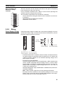
Wiring Precautions
• Separate input leads and power lines to protect the EJ1 from external
noise.
• Use AWG22 (cross-sectional area: 0.326 mm2) to AWG14 (cross-sectional area: 2.081 mm2) twisted-pair cable for power supply and AWG28
(cross-sectional area: 0.081 mm2) to AWG16 (cross-sectional area:
1.309 mm2) for all other cables. The stripping length is 6 to 8 mm.
• Use crimp terminals when wiring the terminals.
• Tighten the terminal screws to a torque of 0.40 to 0.56 N·m.
• Up to two wires of the same size and same type or two crimp terminals
can be inserted into a single terminal.
• Use the following types of crimp terminals for M3 screws.
5.8 mm max.
5.8 mm max.
18
Section 2-2
Wiring Terminals
Wiring Procedure for
Screw-Less Clamp
Terminals
B1
B2
B3
B4
B5
B6
B7
B8
B9
B10
2-2-3
There are two holes for each terminal. The hole on the right is the operating
hole; the hole on the left is the wire hole.
Insert a flat-blade screwdriver with a width of 2.5 mm into the operating hole
and then insert the wiring into the wire hole.
A1
A2
A3
A4
A5
The wire will be clamped when the screwdriver is removed.
Use pin terminals for wiring that match the cross-sectional area of the wiring material.
We recommend the following pin terminals:
Weidmuller H-sleeve Series
A6
A7
A8
A9
A10
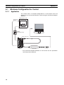
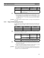
Wiring
Power Supply Voltage
Connect the power supply to models with screw terminals (EDUA) 8 and 9 as
shown below. When using a connector terminal block model (EDUC), connect
the power supply to terminals 9 and 10.
1
1
2
2
3
3
4
4
5
5
6
6
7
7
8
8
9
24-VDC
input power supply
8
9
9
10
Models with Screw
Terminals (EDUA)
Connector Terminal
Block Model (EDUC)
9
10
EDUA
EDUC
Models with Screw Connector Terminal
Terminals (EDUA) Block Model (EDUC)
• If reinforced insulation is required, connect the input and output terminals
to a device without any exposed current-carrying parts or to a device with
standard insulation suitable for the maximum operating voltage of the
power supply I/O section.
• Conforming to Safety Standards
The power supply terminals must be supplied from a SELV, limited-current
source. A SELV (separated extra-low voltage) source is a power supply
having double or reinforced insulation between the primary and the secondary circuits and having an output voltage of 30 V r.m.s. max. and 42.4
V peak max. or 60 VDC max.
Recommended power supply: S8VM Series or S8VS Series (both manufactured by OMRON)
Note
Select a power supply that suits the operating environment.
• To comply with the standards for noise terminal voltage for class A in EN
61326, install a noise filter (Densei Lambda MXB-1206-33 or the equivalent) to the DC line as close as possible to the EJ1.
19
Section 2-2
Wiring Terminals
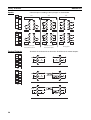
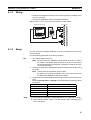
Inputs
Connect inputs according to the input type as shown below.
B1
B2
B3
B4
B5
B6
B7
B8
B9
A1
A2
A3
A4
A5
A6
A7
A8
A9
TC4
B1
B2
B3
B4
B5
B6
B7
B8
B9
A1
A2
A3
A4
A5
A6
A7
A8
A9
TC2
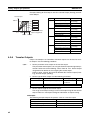
Control Outputs
B1
B2
B3
B4
B5
B6
B7
B8
B9
A1
A2
A3
A4
A5
A6
A7
A8
A9
TC4
TC4
TC2
−
+
B4
A4
B5
A5
B6
A6
A
ch2
−
+
TC4
TC2
−
B
+
B
ch4
B7
A7
B8
A8
B9
A9
B4
A4
B5
A5
B6
A6
ch2
A
−
B
+
B
ch1
TC2
ch3
+
mA
B
V
B
ch4
B7
A7
B8
A8
B9
A9
ch1
Thermocouple inputs
Infrared thermosensor
A
−
+
B4
A4
B5
A5
B6
A6
ch2
A
+
mA
B
V
B
ch3
−
+
B7
A7
B8
A8
B9
A9
A1
A2
A3
A4
A5
A6
A7
A8
A9
V
+
−
+
mA
V
Analog inputs
Terminals B1 to B3 and A1 to A3 on the TC4/TC2 are for control outputs.
B1
OUT2
B2
OUT1
+
+
+
12 VDC
12 VDC
12 VDC
B3
+
A1
OUT4
A2
12 VDC
−
−
OUT3
A3
TC4
B1
OUT2
B2
OUT1
+
+
A1
OUT4
12 VDC
A2
OUT3
12 VDC
B3
A3
−
COM
TC2 with Pulse Outputs
TC2
B1
OUT2
B2
OUT1
+
A1
4-20/0-20 mA DC
+
OUT4
A2
OUT3
4-20/0-20 mA DC
B3
−
A3
COM
TC2 with Linear Outputs
20
+
mA
ch3
TC4
B1
B2
B3
B4
B5
B6
B7
B8
B9
−
ch4
ch1
Platinum resistance
thermometer inputs
+
Section 2-2
Wiring Terminals
Output type
Specifications
Pulse voltage Output voltage:
12 VDC ±15% (PNP)
outputs
Max. load current: 21 mA, with short circuit protection circuit.
Transistor
Max. applicable voltage: 30 VDC
outputs
Max. load current:
100 mA
Residual voltage:
1.5 V max., Leakage current: 0.4 mA max.
Current out- Current output range:
4 to 20 mA (resolution: approx. 2,800)
puts
0 to 20 mA (resolution: approx. 3,500)
Load:
500 Ω max.
Auxiliary Outputs
B1
B2
B3
B4
B5
B6
B7
B8
B9
Auxiliary outputs are sent from pins B1 to B6 with the HFU, and from pins 3 to
5 with the EDUA. When using an EDUC, auxiliary outputs are sent from pins 3
to 6.
A1
A2
3
A3
SUB2
A4
4
A5
B1
SUB1
SUB4
A6
5
COM
B2
A7
SUB3
A8
Models with Screw Terminals (EDUA)
B3
A9
COM
HFU
3
1
1
2
2
3
3
4
4
5
5
6
7
6
7
8
8
9
9
EDUA
10
Models with
Screw
Terminals
(EDUA)
Connector
Terminal
Block Model
(EDUC)
EDUC
SUB2
B4
4
SUB2
COM
B5
SUB1
5
B6
COM
SUB1
6
COM
Connector Terminal Block Model (EDUC)
HFU
EDU
Output type
Specifications
Transistor
Max. operating voltage: 30 VDC
outputs
Max. load current:
50 mA
Residual voltage:
1.5 V max., leakage current: 0.4 mA max.
CT Inputs (Only
Controllers with Pulse
Outputs)
When the heater burnout (HB), heater overcurrent (OC), or heater short (HS)
alarm is to be used, connect a Current Transformer (CT) across terminals A8
and A9 or terminals A7 and A9 (no polarity) on the TC2.
21
Section 2-2
Wiring Terminals
B1
B2
B3
B4
B5
B6
B7
B8
B9
A1
A2
A3
A4
A5
A6
A7
A8
A9
A7
CT2
A8
CT1
A9
TC2
• Use a E54-CT1 or E54-CT3 Current Transformer.
Connect event inputs across terminals A4 and A6 for the TC2 and terminals
A1 and A6 for the HFU.
A1
A2
A3
A4
A5
A6
A7
A8
A9
TC2
B1
B2
B3
B4
B5
B6
B7
B8
B9
A1
A1
EV4
A2
A2
EV3
A3
A3
HFU
B1
B2
B3
B4
B5
B6
B7
B8
B9
A4
A1
A2
A3
A4
A5
A6
A7
A8
A9
A4
EV2
TC2
Event Inputs
A5
A5
EV1
A6
Contact inputs
A6
+
EV4
+
EV3
−
+
EV2
+
EV1
−
Non-contact inputs
HFU
• The inflow current is approximately 4 mA.
• Use event inputs under the following conditions:
Contact inputs
Non-contact
inputs
Communications
22
ON: 1 kΩ max., OFF: 100 kΩ min.
ON: Residual voltage: 1.5 V max., OFF: Leakage current: 0.1 mA
max.
• For communications with the host, connect communications across terminals B7 and B8 or terminals A7 to A9 on the HFU or connect across terminals 1 and 2 or terminals 6 and 7 on the EDU. When using a connector
terminal block model, connect communications across terminals 7 and 8.
Section 2-2
Wiring Terminals
B1
B2
B3
B4
B5
B6
B7
B8
B9
A1
A2
RDB (+)
B (+)
B7
A7
SD
SDB (+)
RDA (−)
A (−)
B8
A8
RD
SDA (−)
A9
SG
A3
A4
A5
A6
DO NOTUSE
A7
A8
RS-422
A9
RS-232C
RS-485
RS-422
Port C communications
HFU
1
1
2
2
3
3
4
4
5
6
5
6
7
7
8
8
Models with
Screw
Terminals
(EDUA)
Connector
Terminal
Block Model
(EDUC)
B (+)
1
B (+)
6
7
A (−)
2
A (−)
7
8
9
9
RS-485
RS-485
EDUA
10
Port A communications
Port B communications
Models with
Screw
Terminals
(EDUA)
Connector
Terminal
Block Model
(EDUC)
EDUC
Note
• If there are problems with communications noise performance when using
the port A connector, connect 110 to 125 Ω of terminating resistance
across terminals 1 and 2 of port A on the EDU.
• Specify both ends of the transmission path, including the host computer,
as end nodes (i.e., connect terminators to both end). The minimum terminating resistance is 54 Ω.
■ Connection Example
Host
R
Shield
+
−
FG
EJ1
EDUA
B (+) 6
A (−) 7
EJ1
RS-485
EDUA
Terminator
110 to 125 Ω (1/2 W)
B (+) 6
A (−) 7
R
23
Section 2-2
Wiring Terminals
• The RS-485 connection can be either 1: 1 or 1: N. RS-232C connections
can only be 1: 1. A maximum of 64 Units (including the host) can be connected in 1: N systems. The maximum total cable length is 500 m. Use
AWG28 (cross-sectional area: 0.081 mm2) to AWG16 (cross-sectional
area: 1.309 mm2) shielded twisted-pair cable.
Cross-sectional area of conductor
AWG28: 0.081 mm2
AWG16: 1.309 mm2
Connecting to the G3ZA Multi-channel Power Controller or G3PW Power Controller
Connecting to the G3ZA Power Controller
CN1
READY
SD/ RD
SW1
OCC
SW2
ERROR
Set SW2 to 3 (57.6 kbps).
Connect the G3ZA
Connecting Cable to the
CN1 connector on the
bottom of the TC Unit.
24
Connect the black line with a white stripe
to terminal 7 on the G3ZA and the black
line with no stripe to terminal 8.
EJ1-CBLA050 (order separately) (cable
length: 5 m)
Section 2-2
Wiring Terminals
Connecting to the G3PW Power Controller
ADJ
%(IN)
%(DUTY)
%(OUT)
%(PHASE)
A
COMM
SET EV
LVL
ENT
RST
G3PW
B(+)
RS-485
A(-)
1
2
3
4
5
6
REMOTE SET
DUTY SET
7
8
9
10
11
12
13
14
1
2
+
+
ALARM1(NPN)
+
ALARM2(NPN)
EVENT
RESET
3
+
-
1-5V
-
4
5
100-240VAC
4-20mA
See
Manual
Set the baud rate to 57.6 kbps
(default value) using key
operations. For details, refer to
the G3PW Operation Manual.
N
N
L
T1
L1
L
Time-lag fuse
Load
Fast-acting fuse
Connect the black line with a white stripe
to terminal 1 on the G3ZA and the black
line with no stripe to terminal 2.
EJ1-CBLA050 (order separately)
(cable length: 5 m)
1
B (+)
2
A (−)
CN1
Use a JST Mfg. Co. Ltd. PA connector.
Housings
Model: PAP-02V-S
Crimp Terminals
Model: SPHD-001T-P0.5
Use an EJ1-CBLA050 Cable (manufactured by OMRON).
TC4/2
The EJ1 contains 120 Ω of terminating resistance. Connect a terminating
resistor (110 to 125 Ω, 1/2 W) only to the end G3ZA node.
25
Section 2-3
Using Tool Ports
2-3
Using Tool Ports
Tool ports are used to make EJ1 settings using the EST2-2C-MV@ CXThermo Support Software.
The E58-CIFQ1 USB-Serial Conversion Cable is required to make the connection.
2-3-1
Procedure
1,2,3...
1. Turn ON the power to the EJ1.
Note
Do not connect the E58-CIFQ1 when power to the EJ1 is OFF. If
the Cable is connected when the power to the EJ1 is OFF, power
will be supplied from the computer and impose a load on the internal circuits of the EJ1.
2. Connect the Cable.
Connect the computer's USB port with the port A connector on the EJ1 using the Cable.
Port A connector
E58-CIFQ1
Computer
EDU Front View
3. Install the driver.
A driver must be installed to use the Cable.
• When the Cable is connected with the computer, the OS will detect a
new device.
Follow the installation wizard instructions and install the driver.
Note
For details on installation methods, refer to the user's manual for
the E58-CIFQ1 USB-Serial Conversion Cable.
4. Make the communications port settings.
The USB-Serial Conversion Cable is used to communicate with the COM
port of the computer.
Set the communications port (COM port) number to be used for the CXThermo Support Software to the COM port assigned to the Cable.
26
Section 2-4
Unit Configuration Examples
2-4
Unit Configuration Examples
Minimal Configuration
• The two auxiliary alarm outputs (transistor outputs) provided on the End
Unit can be used.
• The G3ZA or G3PW can be connected.
EJ1@-TC4
or
EJ1@-EDU
EJ1@-TC2
Port A (connector): USB connection
can be made using the E58-CIFQ1
(sold separately).
CX-Thermo for
setting
Computer
Multiple Units without an
HFU
• The two auxiliary alarm outputs (transistor outputs) provided on the End
Unit can be used.
• G3ZA or G3PW outputs can be used.
• Distributed placement is possible by using multiple End Units.
EJ1@-TC4
or
EJ1@-TC2
EJ1@-EDU
Port A (connector): USB connection
can be made using the E58-CIFQ1
(sold separately).
CX-Thermo for setting
Computer
Port B: RS-485 (CompoWay/F)
PLC
G3ZA
G3ZA
PT
Computer
G3ZA
27
Section 2-4
Unit Configuration Examples
Multiple Units with an HFU
• The two auxiliary alarm outputs (transistor outputs) provided on the End
Unit can be used.
• In addition to the two auxiliary alarm outputs provided on the End Unit, the
four event inputs and four transistor outputs on the HFU can be used.
• G3ZA or G3PW outputs can be used.
• Distributed placement is possible by using multiple End Units.
EJ1@-HFU
EJ1@-TC4
or
EJ1@-TC2
EJ1@-EDU
PLC
Port A (connector): USB connection
can be made using the E58-CIFQ1
(sold separately).
CX-Thermo for setting
Computer
Port B is used for distributed
placement.
G3ZA
28
G3ZA
G3ZA
Section 2-4
Unit Configuration Examples
2-4-1
Connection Precautions
Restrictions on the Number of Units that Can Be Connected
• Unit numbers 0 to 63 can be used for EJ1-HFU and EJ1-TC4/TC2 Units.
• Up to 16 Units, including the HFU, can be connected side by side.
Note
Precautions When Using
an HFU
EDU Units are not counted in the number of Units that can be connected.
• One HFU can control up to 16 TC4/TC2 Units. With version V1.2 , one
HFU can control up to 32 TC4/TC2 Units.
• The unit numbers of the TC4/TC2 Units can be set to between 0 and 31.
• To connect 16 or more TC4/TC2 Units, Communications Cables must be
used to distribute Unit positioning because the maximum number of Units
that can be connected horizontally will be exceeded.
• When using Communications Cables to distribute TC4/TC2 Unit positioning, connect the cables to port B on the End Units.
• If distributed positioning is used for an EJ1, power must be supplied separately to the terminal block on the End Units.
Note
When using distributed positioning, turn ON power to the distributed Units first
or turn ON power to the HFU and distributed Units simultaneously. Even if this
is done, there may still be problems with the startup timing depending on the
EJ1 configuration and power supply capacity. If problems occur at startup,
increase the delay between turning ON the power to the distributed Units and
the HFU.
One HFU can manage up to 32 TC Units (4 channels × 32 Units = 128 channels)
EDU Units are not included in the number of Units that can be managed.
Turn ON
pin 8 on
SW2.
EJ1@-HFU
EJ1@-TC4
or
EJ1@-TC2
EJ1@-EDU
EJ1@-TC4
or
EJ1@-TC2
EJ1@-EDU
Up to 16 Units can be connected side by side.
EDU Units are not counted in the number of Units that can be connected.
Precautions when Not
Using an HFU
Note
• Up to 16 TC4/TC2 Units can be connected horizontally to one End Unit. If
End Units are connected with Communications Cables for distributed
position, then up to 64 Basic Units can be connected to one host device.
(1) The host device and End Units are not counted when calculating the limit
of 64 Basic Units.
(2) Set the unit numbers of the Basic Units to between 0 and 63. Be sure not
to set the same number for more than one Basic Unit.
• If distributed positioning is used for an EJ1, power must be supplied separately to the terminal block on the End Units.
29
Section 2-4
Unit Configuration Examples
• When using distributed position, connect like ports on the End Units.
• If port A on the terminal blocks is connected for distributed position, then
the port A connector can be connected to a computer using an E58CIFQ1 USB-Serial Conversion Cable to use the CX-Thermo to set the
parameters for the distributed EJ1.
EJ1@-TC4 or EJ1@-TC2
EJ1@-EDU
Up to 64 Basic Units can be connected
using distributed placement (4 channels ×
64 Units = 256 channels).
EJ1@-TC4 or EJ1@-TC2
Wiring for Distributed
Placement
EJ1@-EDU
Group A
Terminator
110 to 125 Ω
(1/2 W)
1
2
3
4
5
6
7
8
9
Host device
FG
Terminator
110 to 125 Ω
(1/2 W)
24 VDC
Group B
Terminator
110 to 125 Ω
(1/2W)
1
2
3
4
5
6
7
8
9
30
RS-485
Terminator
110 to 125 Ω (1/2 W)
24 VDC
RS-485
Section 2-4
Unit Configuration Examples
Note
Connecting the G3ZA or
G3PW to the EJ1
Note
Wire the connections indicated with dotted lines when settings for all EJ1
Controllers are being made from one port A connector. If the connections indicated with dotted lines are not wired, the settings for group A can be made
only using the port A connector for group A and the settings for group B can
be made only using the port A connector for group B.
• Up to 8 G3ZA Multi-channel Power Controllers or G3PW Power Controllers can be connected to one TC4/TC2 Unit. However, the G3ZA and
G3PW cannot be used together.
Either turn ON the power to the G3ZA or G3PW first, or turn ON the power to
the G3ZA or G3PW simultaneously with the EJ1.
Connect a terminating resistor
only to the end G3ZA node.
110 to 125 Ω (1/2 W)
+
7
8
−
RS-485
EJ1@-TC4
or
EJ1@-TC2
EJ1C-EDU
G3ZA
Up to 8 G3ZA Power Controllers can be
connected to one TC Unit.
31
Section 2-4
Unit Configuration Examples
Restrictions on
Connections and
Placement
• Always connect the HFU on the left side of the TC4/TC2 Units.
Incorrect
EJ1@-TC4
or
EJ1@-TC2
32
EJ1@-HFU
Correct
EJ1@-HFU EJ1@-TC4
or
EJ1@-TC2
SECTION 3
Typical Control Examples
This section describes the basic applications of the EJ1 using specific control examples.
3-1
3-2
3-3
3-4
Minimum Configuration for Control . . . . . . . . . . . . . . . . . . . . . . . . . . . . . . .
34
3-1-1
Application . . . . . . . . . . . . . . . . . . . . . . . . . . . . . . . . . . . . . . . . . . . .
34
3-1-2
Wiring . . . . . . . . . . . . . . . . . . . . . . . . . . . . . . . . . . . . . . . . . . . . . . . .
35
3-1-3
Setup . . . . . . . . . . . . . . . . . . . . . . . . . . . . . . . . . . . . . . . . . . . . . . . . .
35
3-1-4
Adjustment . . . . . . . . . . . . . . . . . . . . . . . . . . . . . . . . . . . . . . . . . . . .
37
Multi-channel Control. . . . . . . . . . . . . . . . . . . . . . . . . . . . . . . . . . . . . . . . . . .
38
3-2-1
Application . . . . . . . . . . . . . . . . . . . . . . . . . . . . . . . . . . . . . . . . . . . .
38
3-2-2
Wiring . . . . . . . . . . . . . . . . . . . . . . . . . . . . . . . . . . . . . . . . . . . . . . . .
39
3-2-3
Setup . . . . . . . . . . . . . . . . . . . . . . . . . . . . . . . . . . . . . . . . . . . . . . . . .
39
3-2-4
Adjustment . . . . . . . . . . . . . . . . . . . . . . . . . . . . . . . . . . . . . . . . . . . .
40
Control Linked to a Host Device. . . . . . . . . . . . . . . . . . . . . . . . . . . . . . . . . . .
41
3-3-1
Application . . . . . . . . . . . . . . . . . . . . . . . . . . . . . . . . . . . . . . . . . . . .
41
3-3-2
Wiring . . . . . . . . . . . . . . . . . . . . . . . . . . . . . . . . . . . . . . . . . . . . . . . .
42
3-3-3
Setup . . . . . . . . . . . . . . . . . . . . . . . . . . . . . . . . . . . . . . . . . . . . . . . . .
43
3-3-4
Adjustment . . . . . . . . . . . . . . . . . . . . . . . . . . . . . . . . . . . . . . . . . . . .
44
Controlling G3ZA Controllers Connected to Output Devices . . . . . . . . . . . .
45
3-4-1
Application . . . . . . . . . . . . . . . . . . . . . . . . . . . . . . . . . . . . . . . . . . . .
45
3-4-2
Wiring . . . . . . . . . . . . . . . . . . . . . . . . . . . . . . . . . . . . . . . . . . . . . . . .
47
3-4-3
Setup . . . . . . . . . . . . . . . . . . . . . . . . . . . . . . . . . . . . . . . . . . . . . . . . .
48
3-4-4
Adjustment . . . . . . . . . . . . . . . . . . . . . . . . . . . . . . . . . . . . . . . . . . . .
48
33
Section 3-1
Minimum Configuration for Control
3-1
3-1-1
Minimum Configuration for Control
Application
This section shows an example configuration for a small electric oven and
explains how to set up and control the system using the CX-Thermo Support
Software.
Small electric oven
Temperature
Sensor
Heater
G3NA
Solid State Relay
Computer
Port A connector
TC2 EDU
EJ1
E58-CIFQ1
• The CX-Thermo Support Software can be used to set EJ1 parameters
from the personal computer.
34
Section 3-1
Minimum Configuration for Control
3-1-2
Wiring
• Connect the Temperature Sensor to the input terminals according to the
sensor's input type.
• Connect the Solid State Relay to the output terminals.
When an EJ1@-TC2 is used, wire the circuits as shown below.
EJ1@-TC2
Small electric oven
B1
A1
OUT2
B2
OUT1
Temperature
Sensor
A2
B3
A3
B4
A4
IN2
B5
A5
SSR
B6
A6
Heater
B7
A7
IN1
B8
A8
B9
A9
3-1-3
Setup
Use the CX-Thermo Support Software to set EJ1 parameters from the personal computer.
Use the following procedure to set the parameters.
1,2,3...
1. Turn ON the power to the EJ1.
Note
Do not connect the E58-CIFQ1 when power to the EJ1 is OFF. If
the Cable is connected when the power to the EJ1 is OFF, power
will be supplied from the computer and impose a load on the internal circuits of the EJ1.
2. Connect the computer's USB port to the port A connector on the EJ1 using
the Cable.
Note
A driver must be installed to use the Cable.
For details on installation methods, refer to the user’s manual for
the E58-CIFQ1 USB-Serial Conversion Cable.
3. Connect the CX-Thermo Support Software to set the communications protocol.
Select Communications - Settings and set the following communications
parameters.
Serial port
Baud rate
Data length
Stop bits
Parity
Unit number
Note
COM (See note 1.) (E58-CIFQ1 Serial Port)
38400
7
2
Even
(See note 2.)
(1) The serial port (COM port) number depends on the computer's settings.
(2) Verify the unit number, which is set with switches SW1 and SW2 on the
EJ1's front panel.
35
Section 3-1
Minimum Configuration for Control
4. The following table shows the related parameter settings for this example.
CX-Thermo Basic Mode Setting Example
Setting example
EJ1N-TC2A-QNHB 0
---
Remarks
---
CH1
Control in progress parameters
Bank 0
Bank 0 Set Point - CH1
150°C
Bank 0 Proportional Band - CH1
8.0°C
Default
Bank 0 Integral Time - CH1
233 s
Default
Bank 0 Derivative Time - CH1
40.0 s
Default
Bank 0 Alarm Value 1 - CH1
0°C
Bank 0 Alarm Upper Limit Value 1 - CH1 0°C
Upper limit alarm; not used.
Bank 0 Alarm Lower Limit Value 1 - CH1 0°C
Upper limit alarm; not used.
Bank 0 Alarm Value 2 - CH1
0°C
Bank 0 Alarm Upper Limit Value 2 - CH1 0°C
Upper limit alarm; not used.
Bank 0 Alarm Lower Limit Value 2 - CH1 0°C
Upper limit alarm; not used.
Adjustment settings
Manual MV - CH1
0.0%
Disabled in Auto mode
---
---
Heater Burnout 1 Detection
0.0 A
HB alarm OFF
Heater Burnout 2 Detection
0.0 A
HB alarm OFF
---
---
HB/HS/OC settings 1
Control stopped parameters
Input settings
Input Type - CH1
Temperature Unit - CH1
Output settings
Control Period 1
Alarm settings
°C
---
---
2
OUT1 control period: 2 s
---
---
Alarm 1 Type - CH1
2: Upper-limit alarm
Alarm 2 Type - CH1
2: Upper-limit alarm
Operation commands
RUN - CH1
STOP - CH1
Manual - CH1
Auto - CH1
100% AT Execute - CH1
AT Cancel - CH1
36
5: Thermocouple (K)
---
---
Minimum Configuration for Control
3-1-4
Section 3-1
Adjustment
Execute autotuning (AT) to make the PID adjustments.
If self-tuning (ST) is activated, the PID will be automatically calculated when
using standard control. V1.2
Refer to 4-3-8 Tuning.
When the CX-Thermo Support Software is being used, both EJ1 control and
autotuning can be started/stopped using operation commands.
Special Remarks
The CX-Thermo Support Software starts in Basic Mode by default. If you want
to set parameters that are not displayed in Basic Mode, select View - View
Mode and switch to Advanced Mode to enable the advanced settings.
In addition, the View Mode can be set to level group display, or functional
group display. When functional group display is selected, items are grouped
by function rather than displayed separately as they are in the level group display mode.
37
Section 3-2
Multi-channel Control
3-2
3-2-1
Multi-channel Control
Application
In this example configuration, an EJ1 controls a 4-zone heater plate.
NS5
Programmable Terminal
RUN
CJ1W-CIF11
RS-422A Converter
RS-485
Wafer
Temperature
Sensor
Heater plate
Control outputs: Channels 1 to 4
Sensor inputs:
Channels 1 to 4
TC4 EDU
EJ1
G3PB
Solid State Relays for
single-phase heaters
• A single Temperature Controller can handle the 4-zone control if a 4channel Basic Unit (EJ1@-TC4) is used. Up to 16 Basic Units can be connected to one EJ1C-EDU End Unit to expand to a maximum of 64 channels.
Also, the Temperature Controller's settings, operation, and monitoring can
be performed from a Programmable Terminal (without creating a communications program) by using Smart Active Parts (SAP).
38
Section 3-2
Multi-channel Control
3-2-2
Wiring
Connect the Temperature Sensor to the input terminals according to the sensor's input type.
Connect the Solid State Relays for zones 1, 2, 3, and 4 to output terminals
OUT1, OUT2, OUT3, and OUT4, respectively.
When an EJ1@-TC4 is used, wire the circuits as shown below.
EJ1@-TC4
B1
A1
OUT2
SSR
G3PB
B2
OUT1
OUT4
A2
B3
OUT3
A3
B4
A4
IN2
B5
A5
IN4
B6
A6
B7
Temperature
Sensor
A7
IN1
B8
A8
Heater plate
3-2-3
IN3
B9
A9
Setup
The settings are made through communications. The CX-Thermo Support
Software can be connected using an E58-CIFQ1 Connecting Cable to set the
parameters from a personal computer.
The following table shows the related parameter settings for this example.
Related parameters
CH1 - Input Type (Variable type E0, Address 0100)
CH2 - Input Type (Variable type E0, Address 0200)
CH3 - Input Type (Variable type E0, Address 0300)
CH4 - Input Type (Variable type E0, Address 0400)
OUT1 - Control Output 1 Assignment (Variable type E1, Address 0100)
OUT2 - Control Output 2 Assignment (Variable type E1, Address 0200)
OUT3 - Control Output 3 Assignment (Variable type E1, Address 0300)
OUT4 - Control Output 4 Assignment (Variable type E1, Address 0400)
CH1 - Direct/Reverse Operation (Variable type E5, Address 0100)
CH2 - Direct/Reverse Operation (Variable type E5, Address 0200)
CH3 - Direct/Reverse Operation (Variable type E5, Address 0300)
CH4 - Direct/Reverse Operation (Variable type E5, Address 0400)
CH1 - PID/OnOff (Variable type E5, Address 0106)
CH2 - PID/OnOff (Variable type E5, Address 0206)
CH3 - PID/OnOff (Variable type E5, Address 0306)
CH4 - PID/OnOff (Variable type E5, Address 0406)
CH1 - Output Mode Selection (Variable type E5, Address 0107)
CH2 - Output Mode Selection (Variable type E5, Address 0207)
CH3 - Output Mode Selection (Variable type E5, Address 0307)
CH4 - Output Mode Selection (Variable type E5, Address 0407)
CH1 - Set Point (Variable type D4, Address 0100)
CH2 - Set Point (Variable type D4, Address 0200)
Description
0006: K −20.0 to 500.0°C
0006: K −20.0 to 500.0°C
0006: K −20.0 to 500.0°C
0006: K −20.0 to 500.0°C
002F: Channel 1 MV (heating)
004F: Channel 2 MV (heating)
006F: Channel 3 MV (heating)
008F: Channel 4 MV (heating)
0000: Reverse (default)
0000: Reverse (default)
0000: Reverse (default)
0000: Reverse (default)
0000: 2-PID (default)
0000: 2-PID (default)
0000: 2-PID (default)
0000: 2-PID (default)
0000: Standard control (default)
0000: Standard control (default)
0000: Standard control (default)
0000: Standard control (default)
047E: 115.0°C
047E: 115. 0°C
39
Section 3-2
Multi-channel Control
Related parameters
CH3 - Set Point (Variable type D4, Address 0300)
CH4 - Set Point (Variable type D4, Address 0400)
CH1 - Control Period 1 (Variable type E1, Address 0101)
CH2 - Control Period 2 (Variable type E1, Address 0201)
CH3 - Control Period 3 (Variable type E1, Address 0301)
CH4 - Control Period 4 (Variable type E1, Address 0401)
Note
Description
047E: 115. 0°C
047E: 115. 0°C
0000: 0.5 s
0000: 0.5 s
0000: 0.5 s
0000: 0.5 s
• Connect the PT to port B.
• Set the write mode to backup mode.
• Set the PT's communications parameters the same as the port B communications parameters.
3-2-4
Adjustment
Execute autotuning (AT) to make the PID adjustments.
If self-tuning (ST) is activated, the PID will be automatically calculated when
using standard control. V1.2
Refer to 4-3-8 Tuning for details.
40
Section 3-3
Control Linked to a Host Device
3-3
3-3-1
Control Linked to a Host Device
Application
In this example configuration, a CJ1-series PLC controls a reflow oven and an
EJ1 performs temperature control on 6 zones and 12 control loops in the
oven.
NS8
Programmable Terminal
RUN
3G3RV
Inverter
CJ1W-CIF11
RS-422A Converter
RS-485
EJ1
HFU
CJ1-series PLC
RS-232C
Workpiece
RS-422A/485
RS-232C
Processing in
N2 atmosphere
TC4
TC4
TC4
EDU
Sensor
inputs
Control outputs
M
G3NA
Solid State Relays
• If an EJ1@-HFU is used, a ladder program does not have to be created to
exchange data such as temperature readings and alarm status with the
PLC.
Also, up to 16 Basic Units can be connected to a single HFU to expand
the system to a maximum of 64 channels. When using version V1.2 , 32
Basic Units can be connected to a single HFU to expand the system to a
maximum of 128 channels.
41
Section 3-3
Control Linked to a Host Device
3-3-2
Wiring
Connect the Temperature Sensors to the input terminals according to the sensor's input type.
• Connect the Solid State Relays to the output terminals.
• Connect the PLC with an RS-232C communications cable.
Wire the circuits as shown below when using an EJ1@-HFU and three EJ1@TC4 Units.
(The following diagram shows the wiring for just one of the EJ1@-TC4 Units.)
EJ1@-TC4
B1
A1
OUT2
B2
OUT1
OUT4
A2
B3
SSR
G3NA
OUT3
A3
B4
A4
IN2
B5
IN4
A5
B6
A6
Heater
Temperature
Sensor
B7
A7
IN1
B8
IN3
A8
B9
A9
EJ1@-HFU
Serial Communications
Board/Unit
Pin
Signal
2
3
4
5
9
Shell
1
SD
RD
RS
CS
SG
FG
FG
B1
Shield
A1
B2
A2
B3
A3
B4
A4
B5
A5
B6
A6
B7
A7
●SW2 settings (EJ1@-HFU)
SW2
Description
8
A8 RD RS-232C
B9
ON: RS-232C is selected.
CJ1W-CIF11
To NS8
communications
port A
A9 SG
EJ1C-EDU
Signal
1
RDA−
RDB+
SDA−
SDB+
FG
2
42
+
RS-485
● DIP Switch Settings (CJ1W-CIF11)
Pin
Description
1
ON: Terminator connected.
2
ON: 2-wire method
3
ON: 2-wire method
4
Not used
5
OFF: No RS control of RD (continual reception)
6
ON: RS control of SD
Note
SD
B8
−
3
4
5
6
7
8
24 VDC
9
Port B cannot be used when the HFU (EJ1@-HFU) is used.
Section 3-3
Control Linked to a Host Device
3-3-3
Setup
TC4
Refer to 3-2 Multi-channel Control for details on the EJ1@-TC4 settings.
HFU
The settings are made through communications. The CX-Thermo Support
Software can be connected using an E58-CIFQ1 Connecting Cable to set the
parameters from a personal computer.
• The following table shows the parameters related to communications
between the EJ1 and PLC, as well as example settings. Set the unit number of the HFU to 0.
Parameter
Set value
Initial setting level
Port C Communications Baud Rate
Port C Communications Data Length (See note 1.)
Port C Communications Parity (See note 1.)
Port C Communications Stop Bits (See note 1.)
Programless
Common settings
Programless Communications Protocol
Programless Communications Upload Data Area (See note 1.)
Remarks
115.2 (kbps)
8 (bit)
Even
1 (bit)
Default
Default
Default
Default
NT Link (1: N)
DM
Default
Default
Programless Communications Download Data Area (See note 1.)
DM
Default
Programless Communications Upload Start Address (See note 1.)
0
Default
Programless Communications Download Start Address (See note 1.)
1500
Default
Upload settings
Programless Upload Settings 4
Programless Upload Settings 5
Programless Upload Settings 6
Programless Upload Settings 7
Programless Upload Settings 8
Programless Upload Settings 9
Programless Upload Settings 10
Programless Upload Settings 11
Programless Upload Settings 12
Programless Upload Settings 13
Programless Upload Settings 14
Programless Upload Settings 15
Programless Upload Settings 16
Programless Upload Settings 17
Programless Upload Settings 18
Programless Upload Settings 19
.
.
.
Unit No. 1 - Common - Device A Status
Unit No. 1 - CH1 - Process Value
Unit No. 1 - CH2 - Process Value
Unit No. 1 - CH3 - Process Value
Unit No. 1 - CH4 - Process Value
Unit No. 2 - Common - Device A Status
Unit No. 2 - CH1 - Process Value
Unit No. 2 - CH2 - Process Value
Unit No. 2 - CH3 - Process Value
Unit No. 2 - CH4 - Process Value
Unit No. 3 - Common - Device A Status
Unit No. 3 - CH1 - Process Value
Unit No. 3 - CH2 - Process Value
Unit No. 3 - CH3 - Process Value
Unit No. 3 - CH4 - Process Value
Unit No. 0 - Common - End Code
.
.
.
.
.
.
Unit No. 1 - CH1 - Set Point
Unit No. 1 - CH2 - Set Point
Unit No. 1 - CH3 - Set Point
Unit No. 1 - CH4 - Set Point
Unit No. 2 - CH1 - Set Point
Unit No. 2 - CH2 - Set Point
Unit No. 2 - CH3 - Set Point
Unit No. 2 - CH4 - Set Point
Unit No. 3 - CH1 - Set Point
Unit No. 3 - CH2 - Set Point
Unit No. 3 - CH3 - Set Point
Unit No. 3 - CH4 - Set Point
Unit No. 0 - Common - End Code
.
.
.
Download settings
Programless Download Settings 4
Programless Download Settings 5
Programless Download Settings 6
Programless Download Settings 7
Programless Download Settings 8
Programless Download Settings 9
Programless Download Settings 10
Programless Download Settings 11
Programless Download Settings 12
Programless Download Settings 13
Programless Download Settings 14
Programless Download Settings 15
Programless Download Settings 16
Note
(1) Displayed when the CX-Thermo's View Mode is set to Advanced Mode.
43
Section 3-3
Control Linked to a Host Device
Note
• The Programmable Terminal and E58-CIFQ1 Connecting Cable cannot
be connected at the same time.
• When connecting the cable for the Support Software to an EJ1C-EDU
End Unit, either turn OFF the Programmable Terminal's power supply or
switch the Programmable Terminal's screen to the system menu.
PLC
The following example settings are for communications with port 2 of a CJ1WSCU41 Serial Communications Unit.
Port 2: User/custom settings
Port 2: Serial communications mode
Port 2: Baud rate
Port 2: NT Link (1: N) maximum unit number
3-3-4
Custom settings
NT Link (1: N)
High-speed
0
Adjustment
Execute autotuning (AT) to make the PID adjustments.
If ST is activated, the PID will be automatically calculated when using standard control. V1.2
Refer to 4-3-8 Tuning for details.
44
Section 3-4
Controlling G3ZA Controllers Connected to Output Devices
3-4
3-4-1
Controlling G3ZA Controllers Connected to Output
Devices
Application
In this example configuration, G3ZA Multi-channel Power Controllers are used
to control the temperature in a 4-zone heater plate with a single control loop
by applying a fixed coefficient (slope) to the results of the EJ1's PID calculations.
NS5
Programmable Terminal
RUN
EJ1
TC4 + EDU
CJ1W-CIF11
RS-422A Converter
CN1
RS-485
EJ1C-CBLA050 Cable
EJ1 channel 1 Temperature Sensor
Heater plate
MV 11
MV 12
MV 13
MV 14
EJ1 channel 2 Temperature Sensor
Heater plate
MV 21
MV 22
MV 23
MV 24
Up to 8 Units
EJ1 channel 3 Temperature Sensor
Heater plate
MV 31
MV 32
MV 33
MV 34
EJ1 channel 4 Temperature Sensor
Heater plate
MV 41
MV 42
MV 43
MV 44
G3PA
Power Solidstate Relays
G3ZA
Multi-channel
Power Controllers
Terminating
resistance
• Up to eight G3ZA Controllers can be connected to the EJ1@-TC4 using
the special communications ports. It is not necessary to create a program
for communications between the EJ1 and G3ZA.
• Also, the G3ZA's internal parameters can be set to split a single EJ1
channel's control output into 4 branches (with the G3ZA-4H@03-FLK) or 8
branches (with the G3ZA-8A@03-FLK).
• A slope (coefficient) and offset value can be set for each branch output.
45
Section 3-4
Controlling G3ZA Controllers Connected to Output Devices
Using the G3ZA's MV
Calculations for Slope
(Gradient) Control
EJ1
G3ZA Multi-channel Power Controller
Unit
a11
b11
MV 11
No.1
ch1
SP1
Channel 1
sensor input
RS-485
PV1
PID
PV2
Unit
No.2
PID
b12
MV 12
SSR
a13
b13
MV 13
SSR
a14
b14
MV 14
SSR
a21
b21
MV 21
SSR
a22
b22
MV 22
SSR
a23
b23
MV 23
SSR
a24
b24
MV 24
SSR
a31
b31
MV 31
SSR
a32
b32
MV 32
SSR
a33
b33
MV 33
SSR
a34
b34
MV 34
SSR
a41
b41
MV 41
SSR
a42
b42
MV 42
SSR
a43
b43
MV 43
SSR
a44
b44
MV 44
SSR
RS-485
SP2
Channel 2
sensor input
a12
MV1
MV1
ch2
SSR
MV2
MV2
ch3
SP3
Channel 3
sensor input
RS-485
PV3
PID
Unit
No.3
MV3
ch4
MV3
SP4
Channel 4
sensor input
PV4
PID
MV4
RS-485
Unit
No.4
CN1
MV4
Control value = Source channel MV × Slope (a)
+ Offset (b)
46
Section 3-4
Controlling G3ZA Controllers Connected to Output Devices
3-4-2
Wiring
Connect the Temperature Sensors to the input terminals according to the sensor's input type.
• Connect the EJ1 and G3ZA with the EJ1C-CBLA050 Cable.
• Connect the Solid State Relays to the G3ZA's output terminals.
When using an EJ1@-TC4 and G3ZA-4H203-FLK, wire the circuits as shown
in the following diagram.
G3ZA-4H203-FLK
EJ1@-TC4
B1
ch1
ch2
13
+
14
RS-485
7
15
16
17
OUT4
B2
OUT1
A2
B3
18
OUT3
A3
B4
−
8
To Unit 2
1
ch4
A1
OUT2
SSR
G3PA
ch3
A4
IN2
9
11
Black
Black with white stripe
2
4
B5
A5
A6
B7
6
A7
IN1
B8
A8
Control power
supply
100 to 240 VAC
50 or 60 Hz
IN4
B6
Load power supply
100 to 240 VAC
50 or 60 Hz
Heater plate
IN3
B9
Temperature
Sensor
A9
CN1
EJ1C-CBLA050 Cable
SW1 settings (G3ZA-4H203-FLK)
SW1
1 2 3 4
Unit number
SW2 settings (G3ZA-4H203-FLK)
SW2
Description
3
01 02 03 04
SW2 settings (EJ1@-TC4)
SW2
Description
Baud rate: 57.6 kbps
CJ1W-CIF11
To NS5
Signal
communications
RDA−
port A
RDB+
SDA−
SDB+
FG
DIP Switch Settings (CJ1W-CIF11)
Pin
Description
1
ON: Terminator connected.
2
ON: 2-wire method
3
ON: 2-wire method
4
Not used
OFF: No RS control of RD
5
(continual reception)
6
ON: RS control of SD
7
ON: Use G3ZA
EJ1C-EDU
1
+
RS-485
2
−
3
4
5
6
7
8
24 VDC
9
47
Controlling G3ZA Controllers Connected to Output Devices
3-4-3
Section 3-4
Setup
The settings are made through communications. The CX-Thermo Support
Software can be connected using an E58-CIFQ1 Connecting Cable to set the
parameters from a personal computer.
The following table shows the parameters related to the G3ZA that can be set
from the Temperature Controller, as well as example settings.
Variable type Address
Parameter name
DA
0100
G3ZA
CH1 Slope
Unit number 01
0101
CH2 Slope
0102
0103
0108
0109
010A
010B
0110
0111
0112
0113
0124
0200
0300
0400
Note
Set value
028A: 65.0%
0288: 64.8%
CH3 Slope
028F: 65.5%
CH4 Slope
0280: 64.0%
CH1 Offset
0032: 5.0%
CH2 Offset
0032: 5.0%
CH3 Offset
0032: 5.0%
CH4 Offset
0032: 5.0%
CH1 Source Channel 0001: Channel 1
CH2 Source Channel 0001: Channel 1
CH3 Source Channel 0001: Channel 1
CH4 Source Channel 0001: Channel 1
Offset control
0001: Enabled
G3ZA Unit number 02 Same as G3ZA Unit number 01
G3ZA Unit number 03
G3ZA Unit number 04
• The Programmable Terminal and E58-CIFQ1 Connecting Cable cannot
be connected at the same time.
• When connecting the cable for the Support Software to an EJ1C-EDU
End Unit, either turn OFF the Programmable Terminal's power supply or
switch the Programmable Terminal's screen to the system menu.
3-4-4
Adjustment
Execute autotuning (AT) to make the PID adjustments.
If ST is activated, the PID will be automatically calculated when using standard control. V1.2
Refer to 4-3-8 Tuning for details.
Set the slope and offset values independently to match the system. (The
default value for the slope is 100.0% and the default value for the offset is
0.0%.)
48
SECTION 4
Basic Units (TC4 and TC2) Functions
This section describes the functions of EJ1 Basic Units.
4-1
4-2
4-3
4-4
4-5
Setting Input Specifications . . . . . . . . . . . . . . . . . . . . . . . . . . . . . . . . . . . . . .
51
4-1-1
Input Type . . . . . . . . . . . . . . . . . . . . . . . . . . . . . . . . . . . . . . . . . . . . .
51
4-1-2
Temperature Inputs . . . . . . . . . . . . . . . . . . . . . . . . . . . . . . . . . . . . . .
52
4-1-3
Analog Inputs . . . . . . . . . . . . . . . . . . . . . . . . . . . . . . . . . . . . . . . . . .
52
4-1-4
Input Shift (Correction) . . . . . . . . . . . . . . . . . . . . . . . . . . . . . . . . . .
53
4-1-5
Input Filter . . . . . . . . . . . . . . . . . . . . . . . . . . . . . . . . . . . . . . . . . . . .
56
Setting Output Specifications . . . . . . . . . . . . . . . . . . . . . . . . . . . . . . . . . . . . .
57
4-2-1
Control Output Assignments . . . . . . . . . . . . . . . . . . . . . . . . . . . . . .
57
4-2-2
Control Output Method. . . . . . . . . . . . . . . . . . . . . . . . . . . . . . . . . . .
58
4-2-3
Minimum output ON/OFF width V1.2 . . . . . . . . . . . . . . . . . . . . .
Output ON Scheduling Function . . . . . . . . . . . . . . . . . . . . . . . . . . .
58
4-2-4
4-2-5
Output Scaling . . . . . . . . . . . . . . . . . . . . . . . . . . . . . . . . . . . . . . . . .
61
4-2-6
Transfer Outputs . . . . . . . . . . . . . . . . . . . . . . . . . . . . . . . . . . . . . . . .
62
59
Setting Control Specifications. . . . . . . . . . . . . . . . . . . . . . . . . . . . . . . . . . . . .
64
4-3-1
Starting and Stopping Control . . . . . . . . . . . . . . . . . . . . . . . . . . . . .
64
4-3-2
Selecting the Control Method. . . . . . . . . . . . . . . . . . . . . . . . . . . . . .
65
4-3-3
Selecting the Output Mode . . . . . . . . . . . . . . . . . . . . . . . . . . . . . . . .
68
4-3-4
Setting the Set Point . . . . . . . . . . . . . . . . . . . . . . . . . . . . . . . . . . . . .
71
4-3-5
Setting the SP Ramp . . . . . . . . . . . . . . . . . . . . . . . . . . . . . . . . . . . . .
72
4-3-6
Remote SP . . . . . . . . . . . . . . . . . . . . . . . . . . . . . . . . . . . . . . . . . . . .
73
4-3-7
Setting the Manipulated Variable (MV) . . . . . . . . . . . . . . . . . . . . . .
76
4-3-8
Tuning . . . . . . . . . . . . . . . . . . . . . . . . . . . . . . . . . . . . . . . . . . . . . . . .
78
4-3-9
Disturbance Overshoot Adjustment Function . . . . . . . . . . . . . . . . .
82
4-3-10 Operation during Errors . . . . . . . . . . . . . . . . . . . . . . . . . . . . . . . . . .
84
Setting Alarm Specifications. . . . . . . . . . . . . . . . . . . . . . . . . . . . . . . . . . . . . .
86
4-4-1
Alarm Types . . . . . . . . . . . . . . . . . . . . . . . . . . . . . . . . . . . . . . . . . . .
86
4-4-2
Alarm Value . . . . . . . . . . . . . . . . . . . . . . . . . . . . . . . . . . . . . . . . . . .
87
4-4-3
Alarm Hysteresis . . . . . . . . . . . . . . . . . . . . . . . . . . . . . . . . . . . . . . .
87
4-4-4
Standby Sequence. . . . . . . . . . . . . . . . . . . . . . . . . . . . . . . . . . . . . . .
88
4-4-5
Alarm Latch . . . . . . . . . . . . . . . . . . . . . . . . . . . . . . . . . . . . . . . . . . .
88
4-4-6
Closed in Alarm or Open in Alarm. . . . . . . . . . . . . . . . . . . . . . . . . .
89
4-4-7
Alarm Delay . . . . . . . . . . . . . . . . . . . . . . . . . . . . . . . . . . . . . . . . . . .
89
4-4-8
Alarm SP Selection. . . . . . . . . . . . . . . . . . . . . . . . . . . . . . . . . . . . . .
90
4-4-9
Channel Alarm Status . . . . . . . . . . . . . . . . . . . . . . . . . . . . . . . . . . . .
90
Detecting Current Errors . . . . . . . . . . . . . . . . . . . . . . . . . . . . . . . . . . . . . . . . .
91
4-5-1
CT Assignment (TC2) . . . . . . . . . . . . . . . . . . . . . . . . . . . . . . . . . . .
91
4-5-2
Heater Burnout Alarm (HB Alarm) . . . . . . . . . . . . . . . . . . . . . . . . .
91
4-5-3
Heater Short Alarm (HS Alarm). . . . . . . . . . . . . . . . . . . . . . . . . . . .
98
4-5-4
Heater Overcurrent Alarm (OC Alarm) . . . . . . . . . . . . . . . . . . . . . .
100
49
4-6
4-7
50
Using the Loop Break Alarm (LBA) . . . . . . . . . . . . . . . . . . . . . . . . . . . . . . . .
102
4-6-1
102
Loop Burnout Alarm (LBA) . . . . . . . . . . . . . . . . . . . . . . . . . . . . . . .
Other Functions (TC4 and TC2) . . . . . . . . . . . . . . . . . . . . . . . . . . . . . . . . . . .
104
4-7-1
Bank Function . . . . . . . . . . . . . . . . . . . . . . . . . . . . . . . . . . . . . . . . . .
104
4-7-2
Event Inputs (TC2) . . . . . . . . . . . . . . . . . . . . . . . . . . . . . . . . . . . . . .
105
4-7-3
Internal Buses (TC4 and TC2) . . . . . . . . . . . . . . . . . . . . . . . . . . . . .
106
4-7-4
Using G3ZA Multi-channel Power Controllers . . . . . . . . . . . . . . . .
108
4-7-5
Using the G3PW V1.1 . . . . . . . . . . . . . . . . . . . . . . . . . . . . . . . . . . .
112
Section 4-1
Setting Input Specifications
4-1
4-1-1
Setting Input Specifications
Input Type
Set the input type to match the type of sensor being used.
Note
Variable type
E0/A0
Parameter name
Setting range
Input Type
(Channel) 0 to 29
0 to 30 V1.2
Conditions for use
No special conditions
Default
5
This parameter can be set only when operation is stopped.
List of Input Types
Input type
Specification
Set value
Tempera- Platinum Pt100
ture
resistance
input
thermometer
JPt100
Thermocouple
inputs
ES1B
Infrared
Temperature
Sensor
Analog
inputs
Current
input
Voltage
input
Tempera- Thermoture
couple
0
1
2
3
4
K
5
6
J
7
8
T
9
10
E
11
L
12
U
13
14
N
15
R
16
S
17
B
18
W
19
PLII
20
10 to 70°C
21
60 to 120°C
22
115 to 165°C 23
140 to 260°C 24
4 to 20 mA
25
0 to 20 mA
1 to 5 V
0 to 5 V
0 to 10 V
26
27
28
29
K
30 V1.2
Setting range
(°C)
(°F)
−200 to 850
−300 to 1500
−199.9 to 500.0 −199.9 to 900.0
0.0 to 100.0
0.0 to 210.0
−199.9 to 500.0 −199.9 to 900.0
0.0 to 100.0
0.0 to 210.0
−200 to 1300
−300 to 2300
−20.0 to 500.0
0.0 to 900.0
−100 to 850
−100 to 1500
−20.0 to 400.0
0.0 to 750.0
−200 to 400
−300 to 700
−199.9 to 400.0 −199.9 to 700.0
0 to 600
0 to 1100
−100 to 850
−100 to 1500
−200 to 400
−300 to 700
−199.9 to 400.0 −199.9 to 700.0
−200 to 1300
−300 to 2300
0 to 1700
0 to 3000
0 to 1700
0 to 3000
100 to 1800
300 to 3200
0 to 2300
0 to 4100
0 to 1300
0 to 2300
0 to 90
0 to 190
0 to 120
0 to 240
0 to 165
0 to 320
0 to 260
0 to 500
Any one of the following ranges,
by scaling:
−1999 to 9999
−199.9 to 999.9
−19.99 to 99.99
−1.999 to 9.999
−199.9 to 999.9 −199.9 to 999.9
51
Section 4-1
Setting Input Specifications
4-1-2
Temperature Inputs
■ Temperature Unit
Either °C or °F can be selected.
Variable type
E0/A0
Parameter name
Setting range
Temperature unit
(Channel) 0: °C/1: °F
Default
0
Conditions for use The input type must be set to temperature input.
Note
This parameter can be set only when operation is stopped.
■ Cold Junction Compensation Method
Specifies whether cold-junction compensation is performed in the Temperature Controller or externally.
Enable external cold-junction compensation when using two thermocouples
to measure a temperature difference or using a external cold-junction compensator for even greater precision.
Variable type
E0/A0
Parameter name
Setting range
Cold Junction Compensation
0: External /
Method
(Common) 1: Internal
Default
1
Conditions for use The input type must be set to thermocouple or infrared temperature sensor.
Note
4-1-3
This parameter can be set only when operation is stopped.
Analog Inputs
When an analog input is selected, scaling can be performed as needed by the
control application.
• The Scaling Upper Limit, Scaling Lower Limit, and Decimal Point Position
parameters are used for scaling. These parameters cannot be used when
a temperature input type is selected.
• The Scaling Upper Limit parameter sets the physical quantity to be
expressed by the upper limit value of input, and the Scaling Lower Limit
parameter sets the physical quantity to be expressed by the lower-limit
value of input. The Decimal Point Position parameter specifies the number of digits below the decimal point.
• The following example shows scaling of an analog input (4 to 20 mA).
After scaling, the humidity can be read directly. In this case, the decimal
point is set for 1 digit below the decimal point.
Display
(humidity)
Upper limit (95.0%)
Lower limit (10.0%)
4
52
Input (mA)
20
Section 4-1
Setting Input Specifications
Variable type
Parameter name
Setting range
E0/A0
Scaling Upper Limit
(Channel) −1999 to 9999
(See note.)
Scaling Lower Limit
(Channel) −1999 to 9999
Decimal Point Position (Channel) 0: **** (no decimal point)
1: ***.*
2: **.**
3: *.***
Conditions for use
Note
Default
1000
0
1
The input type must be set to analog input.
This parameter can be set only when operation is stopped.
Always set the Scaling Upper Limit > Scaling Lower Limit.
If the Scaling Lower Limit > Scaling Upper Limit, the larger value will function
as the Scaling Upper Limit.
■
Setting Example
In this example, scaling is set to display 0 to 5 V as 10.0% to 95.0%.
Scaling Upper Limit = 950
Scaling Lower Limit = 100
Decimal Point Position = 1
4-1-4
Input Shift (Correction)
If there is a significant difference between the temperature at the measurement point and the location where the temperature display is needed so that
the display/control performance is unsatisfactory at the present sensor position (measurement point), the temperature difference can be set as an input
shift (correction) value.
Variable type
Parameter name
Setting range
D5/95
Input Value 1 for Input Correction −199.9 to 999.9 EU
(Channel) (See note 1.)
Input Shift 1
(Channel) −199.9 to 999.9 EU
(See note 2.)
Input Value 2 for Input Correction −1999 to 9999 EU
(Channel) (See note 1.)
Input Shift 2
(Channel) −199.9 to 999.9 EU
(See note 2.)
Conditions for use
Note
Default
0
0.0
1000
0.0
No special conditions
(1) The decimal point position is determined by the sensor selection.
(2) The decimal point position is determined by the sensor selection. In this
case, however, the 0 (****) decimal point position setting will be treated as
setting 1 (***.*).
53
Section 4-1
Setting Input Specifications
Simple Shift: Onepoint Shift
The temperature measurements at all points in the sensor range are shifted.
For example, make the following settings if you want to increase the temperature by 1.2°C.
• Input Shift 1 = Input Shift 2 = 1.2
Note
It is not necessary to set the Input Value 1 for Input Correction or Input Value
2 for Input Correction parameters. Leave these parameters set to their default
settings.
When the measured value after the setting is 200°C, the process value will
become 201.2°C
Temperature
Upper
limit
After
shifting
Before
shifting
Input shift value
Lower
limit
Input
0
100%
Advanced Shift: Twopoint Shift
A linear compensation can be applied by setting the Input Value 1 for Input
Correction in Input Shift 1 and independently setting the Input Value 2 for
Input Correction in Input Shift 2. If different shift values are set for Input Shift 1
and Input Shift 2, the slope of the line may be different before and after applying the input shift.
Display
Input Shift 2
After shifting
Before
shifting
Input Shift 1
Input
0
Input Value 1
for Input Correction
Calculating Input
Shift Values
Input Value 2
for Input Correction
Measure the temperature at two points: the present value displayed by the
EJ1 and the location (control target) that needs to be displayed.
Preparations
1. Set the input type to match the sensor being used.
2. Prepare a thermometer capable of measuring the temperature of the control target as shown in the following diagram so that a 2-point shift can be
performed.
500°C
(A) EJ1 Temperature Controller
550°C
(B) Thermometer
54
Section 4-1
Setting Input Specifications
Two-point Shift
Method
1,2,3...
1. Shift the controller readout at two reference temperatures, near room temperature and near the value at which the temperature of the control target
is to be controlled. Bring the temperature of the control target close to room
temperature and close to the set point, and check control target temperature (B) and controller readout (A).
2. Check the temperature of the control target near room temperature (B) and
the controller readout (A), and calculate the temperature difference as
shown below.
Object temperature (B) − Controller readout (A)
Set the temperature difference as Input Shift 1 and set the controller readout (A) as Input Value 1 for Input Correction.
3. Check the temperature of the control target near set-point temperature (B)
and the controller readout (A), and calculate the temperature difference as
shown below.
Object temperature (B) − Controller readout (A)
Set the temperature difference as Input Shift 2 and set the controller readout (A) as Input Value 2 for Input Correction.
4. After you have set the calculated values, check controller readout (A) and
control target temperature (B).
5. In this case, the two-point shift was performed near room temperature and
the set-point temperature, but if you want to improve accuracy near the set
point, perform the two-point shift at points above and below the set-point
temperature. An example shift is shown in the following diagram.
Controller readout (A)
After shifting
Controller readout after shifting (e.g., 550°C)
Controller readout before shifting (e.g., 500°C)
Input Shift 2
Before shifting
Input value 2 for Input Correction
Input value 1 for Input Correction
Controller readout before shifting (e.g., 40°C)
Input Shift 1
Controller readout after shifting (e.g., 25°C)
0
Control target temperature (B)
Room temperature
(e.g., 25°C)
Temperature near set point
(e.g., 550°C)
■ Two-point Shift Example
In this example, the input type is set to K (5): −200°C to 1,300°C.
Check the temperature of the control target.
When room temperature (B) = 25°C,
the Controller readout (A) = 40°C.
When the temperature near the set point (B) = 550°C,
the Controller readout (A) = 500°C.
In this case, the input shift parameters are calculated as follows:
Input Value 1 for Input Correction = Controller readout (A) = 40°C
Input Shift 1 = Object temperature (B) - Controller readout (A) =
25°C − 40°C = −15.00°C
55
Section 4-1
Setting Input Specifications
Input Value 2 for Input Correction = Controller readout (A) = 500°C
Input Shift 2 = Object temperature (B) - Controller readout (A) =
550°C − 500°C = 50.00°C
4-1-5
Input Filter
Sets the time constant of the digital input filter.
The following diagram shows the response of the digital filter to a step-wise
input of amplitude A.
PV before passing through filter
A
PV after passing through filter
0.63 A
(Time
constant)
Time
Input digital filter
Variable type
D5/95
Parameter name
Setting range
Default
Input Digital Filter (Channel) 0.0 to 999.9 Seconds 0.0
Conditions for use No special conditions
56
Section 4-2
Setting Output Specifications
4-2
4-2-1
Setting Output Specifications
Control Output Assignments
The parameters shown in the following diagram can be assigned to each output by setting the control output assignments.
The same parameter can be assigned to different outputs.
OUT1
Settable
parameters
OUT2
OUT3
OUT4
• OUT2, OUT3, and OUT4 can be set in the same way.
• Channels 3 and 4 are supported only by the TC4.
All channels
Disabled
Temperature Controller Error
All Alarm OR
All Alarm AND
Alarm 1 to 3 OR
Alarm 1 to 3 AND
Input Error OR
RSP Input Error OR
HB (Heater Burnout) Alarm OR
HS (Heater Short) Alarm OR
OC (Heater Overcurrent) Alarm OR
*1
*2
Channel 4
Alarm
Channel
3
4 1 to 3
AlltoAlarm
OR
Alarm
1
3
Channel 2
All
Alarm
All Alarm OR AND
Alarm
Channel
1 1 to 3 Input Error
All OR
Alarm AND
Alarm All
1 toAlarm
3
RSP Input Error
Input
Error
All
Alarm
AND
All Alarm OR
Heater
Burnout Alarm
RSP
Input
Error
Input Error
All Alarm AND
HS
(SSR Alarm
Failure) Alarm
Heater
Burnout
RSP Input Error
Input Error
OC (Heater
Overcurrent)
Alarm
HS
(SSR
Failure)
Heater
Burnout Alarm Alarm
RSP Input
Error
Process
Value
OC Failure)
(Heater Overcurrent)
HS (SSR
Alarm Alarm
HB (Heater Burnout) Alarm
Internal
SP
Process
Value
OC (Heater
Overcurrent)
Alarm
HS (Heater Short) Alarm
Local
SP
Internal
Process
Value SP
OC (Heater Overcurrent) Alarm
Remote SP
Local
SP
Internal
SP
Process Value
Control
Remote
SP Output (Heating)
InternalLocal
SP SP
Control
Output (Cooling)
Control
Remote
SP Output (Heating)
Local SP
Transfer
Output
(Heating)
Control Output
(Cooling)
Control
(Heating)
Remote
SP Output
Transfer
Output
(Cooling)
Transfer
(Heating)
Output Output
(Cooling)
ControlControl
Output (Heating)
Transfer
(Cooling)
Transfer
OutputOutput
(Heating)
Control Output (Cooling)
Transfer
(Cooling)
Transfer
OutputOutput
(Heating)
Transfer Output (Cooling)
Note
(1) Temperature Controller Error
The Temperature Controller Error output will turn ON when an bit between bit 0 and bit 13 in the Device A Status is ON. It can be used to output EJ1 error status. Refer to Status Lists on page 256 for details on
Device A Status.
(2) If any parameters other than those marked with *1 and *2 are assigned
to outputs for Controllers with linear outputs, 100% will be output for ON
and 0% will be outputs for OFF. This will also apply to parameters marked
with *2 if the control method is set to ON/OFF control.
Variable type
Note
Parameter name
E1/A1
Control Output 1 Assignment (I/O)
Control Output 2 Assignment (I/O)
Control Output 3 Assignment (I/O)
Control Output 4 Assignment (I/O)
Conditions for use
No special conditions
Setting range
0 to 144
0 to 144
0 to 144
0 to 144
Default
TC4 TC2
47
79
111 32
143 64
These parameters can be set only when operation is stopped.
Refer to Parameter List on page 235 for details on the settings.
57
Section 4-2
Setting Output Specifications
4-2-2
Control Output Method
The time-proportional output method is used for the control output.
The MV determines the percentage of time that the output is ON during each
control period.
ON
100%
80%
60%
40%
20%
OFF
Control
period
Note
Note
4-2-3
Control responsiveness improves as the control period is shortened, but if relays are being used for heater control, the relay lifetime will also be shortened so we recommend using a control
period of at least 20 seconds.
Variable type
E1/A1
Parameter name
Setting range
Control Period 1 to 4
(I/O) 0 to 99 s
Default
2
Conditions for use
Control output must be assigned and set to 2-PID control.
These parameters are not valid for outputs 1 and 2 on Controllers with linear outputs.
This parameter can be set only when operation is stopped. If the parameter is
set to 0, the period will be 0.5 s.
Minimum output ON/OFF width V1.2
Set the minimum output ON/OFF width.
When using output relays, this function can be used to prevent the relay from
deteriorating. The relationship between MV and actual output is shown in the
following diagram.
Actual output %
100
Minimum output
ON/OFF width
Minimum output
ON/OFF width
0
MV %
100
Example:
When the control period is 10 s, the minimum output ON/OFF width is 10.0%,
and the MV is less than 10.0%, the output will be 0%. When the MV is 90.0%
or greater, the output will be 100%.
58
Section 4-2
Setting Output Specifications
Variable type
E1/A1
Parameter name
Setting range
Minimum output ON/OFF
0.0 to 50.0%
width
(IO)
Default
1.0
Conditions for use Control output must be assigned and set to 2-PID control.
These parameters are not valid for outputs 1 and 2 on Controllers with linear outputs.
Note
(1) This parameter can be set only when operation is stopped.
(2) When the control cycle is short due to the 2-ms output resolution, the Unit
may not operate as set. For example, when the Control Cycle = 1 s and
the Output Minimum ON/OFF Duration = 0.1%, the calculation becomes
1 s (1,000 ms) x 0.1% = 1 ms, but the actual output minimum ON/OFF
duration is 2 ms.
!Caution If the Output Minimum ON/OFF Duration is too large, control performance
may suffer.
4-2-4
Output ON Scheduling Function
The ON time for each output can be reduced to one half or one fourth of the
control period to limit the number of outputs in the Unit that are ON simultaneously.
Output ON Scheduling
Method
No offset
1/2
1/4
Note
Number of outputs ON
simultaneously
4
2
1 (No others ON)
Each output's limit
(See note.)
100%
50%
25%
When the MV is assigned to an output, the actual limit is either this value or
the MV limit value, whichever is lower.
Variable type
F0/B0
Parameter name
Setting range
Default
Output ON Scheduling
0: No offset
0
Method
(Common) 1: 1/2
2: 1/4 (invalid for TC2)
Delay between Outputs
0 to 1000 ms
10
(Common) (See note 2.)
Conditions for use Control output must be assigned and set to standard control, 2PID control. A Controller with pulse outputs must be used.
Note
(1) When this parameter has been changed, the new setting becomes effective the next time a software reset is performed for the Unit or the next
time power is turned ON.
(2) Set the Delay between Outputs parameter to an even number. If an odd
number is set, the next smaller even number will be used.
!Caution • Set the Output Mode Selection parameters to Standard Control for all of the
Unit's channels. The Output ON Scheduling function will be disabled if the
parameter is not set to Standard Control.
59
Section 4-2
Setting Output Specifications
• Even if the Output ON Scheduling Method is set, the outputs may be ON at
the same time due to the delay in the output device's operation. In this case,
you can prevent the outputs from being ON simultaneously by setting a
delay with the Delay between Outputs parameter. Refer to the following setting examples for details on using the delay.
• When using both this function and autotuning, always set this function
before performing autotuning. If this function is set after autotuning, control
performance may deteriorate.
• When using this function, set the following parameters to their default settings: Output Scaling Upper Limit 1 to 4, Output Scaling Lower Limit 1 to 4,
and Decimal Point C1 to C4. If these parameters are not set to their
defaults, the Output ON Scheduling function will not operate properly.
• This function will also be applied to manual outputs, outputs during errors,
and outputs while stopped, so these outputs may be lower than their set values.
• When using the Output ON Scheduling function, all of the Unit's outputs will
operate with the OUT1 control period.
• ST will be disabled when using the Output ON Scheduling Method. V1.2
Example 1 Delay between Outputs = 0 ms
Unit
Control period
Output ON Scheduling Method
Delay between Outputs
MV for all channels
TC4
10 s
1/4 (Limit to 25% of the maximum MV.)
0 ms
20%
2 s = 10 s × 20%
OUT1
Delay between Outputs: 0 ms
OUT2
2.5 s = 10 s × 25%
OUT3
OUT4
Control period: 10 s
Example 2 Delay between Outputs = 1 s
Unit
Control period
Output ON Scheduling Method
Delay between Outputs
MV for all channels
60
TC4
10 s
1/4 (Limit to 25% of the maximum MV.)
1,000 ms = 1 s
20%
Section 4-2
Setting Output Specifications
2 s = 10 s × 20%
OUT1
Delay between Outputs: 1,000 ms = 1 s
OUT2
2.5 s = 10 s × 25%
OUT3
OUT4
Control period: 10 s Delay between outputs
for four channels
Note
4-2-5
The Delay between Outputs parameter can be set to offset the ON
time for each output. The delay between outputs will, however, create an OFF period between outputs, making it appear that the control period has increased. The actual power is 2/(10 + 4) × 100 =
14.3%.
Output Scaling
A slope (gradient) and offset can be set for each value selected with the control output assignment.
The value selected with the control output assignment will be 100% when it
equals the Output Scaling Upper Limit and the value will be 0% when it equals
the Output Scaling Lower Limit.
The decimal point positions for the Output Scaling Upper and Lower Limits
are set with the Decimal Point C1 to C4 parameters. Change the decimal
point position setting if necessary.
Variable type
E1/A1
Conditions for use
Note
Parameter name
Setting range
Output Scaling Upper Limit 1 to 4 −1999 to 9999
(I/O)
Output Scaling Lower Limit 1 to 4 −1999 to 9999
(IO)
Decimal Point C1 to C4
(IO) 0: **** (no decimal point)
1: ***.*
2: **.**
3: *.***
Default
100
0
0
The Control Method must be set to 2-PID Control and the
Control Output Assignment must be set to Control output
(heating) or Control output (cooling).
(1) These parameters can be set only when operation is stopped.
(2) Use 40% AT when output scaling has been set. If 100% AT is used, hunting will occur.
61
Section 4-2
Setting Output Specifications
Example: Making All TC4 Outputs into CH1 Control Output (Heating) with Different Slopes
Actual output
100.0%
Output 1
Output
Parameter name
Output 1
Control output 1 assignment
Output 2
Set value
CH1 Control output (heating)
Output Scaling Upper Limit 1 100
Output Scaling Lower Limit 1 0
Output 3
0
Output 4
0.0% 40.0% 80.0%
Output 2
Set value of control
output assignment
Control output 2 assignment
CH1 Control output (heating)
Output Scaling Upper Limit 2 80
Output Scaling Lower Limit 2 0
60.0% 100.0%
Output 3
Decimal Point C2
0
Control output 3 assignment
CH1 Control output (heating)
Output Scaling Upper Limit 3 60
Output Scaling Lower Limit 3 0
Output 4
Decimal Point C3
0
Control output 4 assignment
CH1 Control output (heating)
Output Scaling Upper Limit 4 40
Output Scaling Lower Limit 4 0
Decimal Point C4
4-2-6
0
Transfer Outputs
Output 1 and output 2 on Controllers with linear outputs can be used as transfer outputs. Use the following procedure.
1,2,3...
1. Set the parameter to be output on the transfer output.
The parameter to be output is set using the Control Output Assignment parameter. Select one of the following values. Refer to 4-2-1 Control Output
Assignments for details on the assigning the control output.
Process Value, Internal SP, Local SP, Remote SP, Transfer Output (Heating), Transfer Output (Cooling)
2. Set the type of linear output. Use the following parameter.
Variable type
E1/A1
Parameter name
Setting range
Linear Output 1/2 Type (I/O) 0: 4-20 mA
1: 0-20 mA
Conditions for use
A Controller with linear outputs must be used.
Default
0
3. Set the output range for the transfer output.
The range set for output scaling is used as the output range for the transfer
output. Refer to 4-2-5 Output Scaling for information on output scaling.
■
Example:
The following example outputs the process value on a transfer output.
Parameter
Input Type
Control Output 1 Assignment
Linear Output 1 Type
62
Default
6 (−20.0 to 500.0°C)
43 (channel 1 process value)
1 (0 to 20 mA)
Section 4-2
Setting Output Specifications
Parameter
Output Scaling Upper Limit 1
Output Scaling Lower Limit 1
Decimal Point C1
Default
300
0
0
Transfer output
(mA)
20
Process value (°C)
0
300.0
500.0
Reverse scaling can also be performed with output scaling.
Transfer output
(mA)
Reverse scaling
20
4
0
Transfer output (heating) (%)
0
Output Scaling
Upper Limit
100
Output Scaling
Lower Limit
63
Section 4-3
Setting Control Specifications
4-3
4-3-1
Setting Control Specifications
Starting and Stopping Control
■ Start Control (RUN) and Stop Control (STOP)
The following two methods can be used to start/stop control. For details, refer
to the corresponding pages.
(1) Starting/stopping control with an operation command: 6-4-11 Operation
Commands
(2) Starting/stopping control with an event input: 4-7-2 Event Inputs (TC2)
■ Operation After Power ON
The operation after power goes ON can be set to Continue, Stop, or Manual
mode operation. This setting also applies to operation after a software reset.
Note
Operation
After Power ON
Continue
RUN/STOP
Auto/Manual
Manipulated
variable
Stop
RUN/STOP
Auto/Manual
Manipulated
variable
Manual mode
RUN/STOP
Auto/Manual
Manipulated
variable
64
Variable type
F0/B0
Parameter name
Setting range
Operation After Power ON
0: Continue
(Common) 1: Stop
2: Manual Mode
Conditions for use
No special conditions
Default
0
This parameter can be set only when operation is stopped.
When this parameter has been changed, the new setting becomes effective
the next time a software reset is performed for the Unit or the next time power
is turned ON.
Operation
2-PID control
Retains the status that existed before power went OFF.
Retains the status that existed before power went OFF.
• For Auto mode before power OFF:
MV depends on RUN/STOP status. When set to RUN,
operation starts from the initial value. When set to STOP,
operation starts from the MV at Stop parameter setting.
• For Manual mode before power OFF:
The manipulated variable from before power was interrupted is maintained.
Stop
Retains the status that existed before power went OFF.
• For Auto mode before power OFF:
Operation starts from the MV at Stop parameter setting.
• For Manual mode before power OFF:
The manipulated variable from before power was interrupted is maintained.
Retains the status that existed before power went OFF.
Manual
• For Auto mode before power OFF:
Operation starts from the MV at Stop parameter setting.
• For Manual mode before power OFF:
The manipulated variable from before power was interrupted is maintained.
ON/OFF control
Same as 2-PID control
Auto
0.0% or 100.0%
Same as 2-PID control
Auto
0.0%
-------
Section 4-3
Setting Control Specifications
4-3-2
Selecting the Control Method
The control method can be set to either 2-PID control or ON/OFF control.
Note
ON/OFF Control
Variable type
E5/A5
Parameter name
PID/OnOff (Channel)
Conditions for use
No special conditions
Setting range
0: 2-PID control
1: ON/OFF control
Default
0
This parameter can be set only when operation is stopped.
In ON/OFF control, the control output turns OFF when the currently controlled
temperature reaches a preset set point. When the manipulated variable turns
OFF, the temperature begins to fall and the control output is turned ON again.
This operation is repeated at a certain level. The Hysteresis (Heating) parameter determines how much the temperature must fall before the control output
is turned ON again. Also, the Direct/Reverse Operation parameter determines
whether the manipulated variable is increased or decreased in response to an
increase or decrease in the process value.
■ Hysteresis
ON/OFF control incorporates a hysteresis setting to stabilize operation when
switching ON and OFF. The width of the hysteresis loop determines the sensitivity.
• The control output (heating) and control output (cooling) hysteresis settings are made with the Hysteresis (Heating) and Hysteresis (Cooling)
parameters, respectively.
• The sensitivity of standard control (heating or cooling) is set with the Hysteresis (Heating) parameter, regardless of the setting of the Direct/
Reverse Operation parameter.
• The Hysteresis (Cooling) parameter is effective only when using heating/
cooling control.
Hysteresis (Heating)
ON
ON
PV
OFF
Set point
Heating control
Note
Hysteresis (Cooling)
PV
OFF
Set point
Cooling control
Variable type
D5/95
Parameter name
Setting range Default
Hysteresis (Heating) (Channel) 0.1 to 999.9 EU 1.0
Hysteresis (Cooling) (Channel) 0.1 to 999.9 EU 1.0
Conditions for use
The control method must be set to ON/OFF control.
The decimal point position is determined by the sensor selection. In this case,
however, the 0 (****) decimal point position setting will be treated as setting 1
(***.*).
65
Section 4-3
Setting Control Specifications
■ Three-position Control
In heating/cooling control, a dead band area can be set where the MV is 0%
for both heating and cooling. with a dead band, 3-position control can be
achieved.
Dead band
Hysteresis (Heating)
Hysteresis (Cooling)
ON
Heating side
Cooling side
OFF
PV
Set point
2-PID Control (Twodegrees-of-freedom
PID)
The proportional band (P), integral time (I), and derivative time (D) must be
set for 2-PID control.
■ PID Settings
When the control characteristics are unknown, perform autotuning (AT) or
self-tuning (ST with V1.2 ). When AT (or ST with V1.2 ) is executed, the optimum PID constants for the set point at that time are set automatically.
When the control characteristics are already known, the PID parameters can
be set directly to adjust control. The PID parameters are set with the Proportional Band (P), Integral Time (I), and Derivative Time (D) parameters.
Note
Refer to 4-3-8 Tuning for details on autotuning or self-tuning (ST
with V1.2 ).
Variable type
D0/90
Conditions for use
Note
Parameter name
Setting range
Proportional Band (BANK) 0.1 to 999.9 EU
(See note 1.)
Integral Time
(BANK) 0 to 3999 Seconds
Derivative Time
(BANK) 0.0 to 999.9 Seconds
Default
8.0
233
40.0
The control method must be set to 2-PID control.
(1) Refer to 4-7-1 Bank Function for details on banks.
(2) The decimal point position is determined by the sensor selection. In this
case, however, the 0 (****) decimal point position setting will be treated as
setting 1 (***.*).
• Proportional action: In proportional action, the MV is proportional to the
deviation (control error).
• Integral action:
66
This control action produces an output that is proportional to the time integral of the control error. An offset normally occurs in proportional control, so
proportional action is used in combination with integral action. As time passes, this offset disappears
and the control temperature (process value) matches
the set point.
Section 4-3
Setting Control Specifications
• Derivative action:
This control action produces an output that is proportional to the rate of change of the input. Since proportional control and integral control correct for errors in
the control result, the control system will be slow to
respond to sudden changes in temperature. The
derivative action performs a corrective action by
increasing the MV in proportion to the slope of the
temperature change.
• Effect of Changes to P (Proportional Band)
Decreased P
Set value
The curve rises gradually and the
settling time is long, but overshooting
is prevented.
Overshooting and hunting occur, but
the set value is reached quickly and
the temperature stabilizes.
Set value
Increased P
Increased I
Set value
Decreased I
Set value
• Effect of Changes to I (Integral Time)
It takes a long time for the process
value to reach the set point. It takes
time to achieve a stable state, but
overshooting, undershooting, and
hunting are reduced.
Overshooting and undershooting
occur. Hunting occurs. The process
value rises quickly.
Decreased D
Set value
Increased D
Overshooting, undershooting, and
the settling time are reduced, but fine
hunting occurs on the changes themselves.
Set value
• Effect of Changes to D (Derivative Time)
Overshooting and undershooting are
increased and it takes time for the
process value to reach the set point.
■ Proportional Band x 10 Compensation
When this parameter is set to Enabled, the proportional band is increased by
a factor of 10. Use this parameter when the proportional band setting range is
insufficient.
Note
Variable type
F0/B0
Parameter name
Setting range
Proportional Band × 10
0: Disabled
Compensation
(Common) 1: Enabled
Conditions for use
The control method must be set to 2-PID control.
Default
0
When this parameter has been changed, the new setting becomes effective
the next time a software reset is performed for the Unit or the next time power
is turned ON.
67
Section 4-3
Setting Control Specifications
■ Setting the Alpha
This parameter sets the 2-PID constant alpha (α).
Note
4-3-3
Normally, this parameter is left at its default value.
Variable type
D5/95
Parameter name
Setting range
Alpha
(Channel) 0.00 to 1.00
Conditions for use
The control method must be set to 2-PID control.
Default
0.65
Selecting the Output Mode
Either standard control or heating/cooling control can be selected as the output method.
Note
Standard Control
Variable type
E5/A5
Parameter name
Setting range
Default
Output Mode Selection
0: Standard control
0
(Channel) 1: Heating/cooling control
Conditions for use
No special conditions
This parameter can be set only when operation is stopped.
This mode performs standard heating or cooling control. Set the Direct/
Reverse Operation parameter to reverse operation for heating control or direct
operation for cooling control.
■ Direct Operation (Cooling) and Reverse Operation (Heating)
Direct operation (cooling) refers to control where the manipulated variable is
increased in response to an increase in the process value. Alternatively,
reverse operation (heating) refers to control where the manipulated variable is
decreased in response to an increase in the process value.
Manipulated variable
Manipulated variable
100%
100%
0%
Time
Low
Set value
temperature
High
temperature
Direct operation
0%
Time
Low
Set value
temperature
High
temperature
Reverse operation
For example, when the process value (PV) is lower than the set point (SP) in a
heating control system, the manipulated variable increases according to the
difference between the PV and SP. Accordingly, this is “reverse operation” in a
heating control system and “direct operation” in a cooling control system,
which performs the opposite operation.
Note
68
Variable type
E5/A5
Parameter name
Setting range
Default
Direct/Reverse Operation
0: Reverse operation 0
(Channel) 1: Direct operation
Conditions for use
No special conditions
This parameter can be set only when operation is stopped.
Section 4-3
Setting Control Specifications
Heating/Cooling
Control
To perform heating/cooling control, assign the control output (cooling) function
to one of the outputs. For example, when you want to perform heating/cooling
control with channel 1, assign channel 1 control output (cooling) to one of the
outputs.
• Refer to 4-2-1 Control Output Assignments for details on assigning the
control output for cooling.
• The Cooling Coefficient and Dead Band parameters must be set for this
PID control, in addition to the Proportional Band (P), Integral Time (I), and
Derivative Time (D) parameters.
■ Cooling Coefficient
If the heating characteristics and cooling characteristics of the control object
are very different and good control characteristics cannot be achieved with the
same PID constants, the cooling coefficient can be used to adjust the proportional band (P) for the control output assigned to cooling. Use this to achieve
balanced control between the heating side and cooling side.
The proportional bands (P) for the control outputs assigned to the heating/
cooling sides can be calculated using the following equations.
• P for the heating side = P
• P for the cooling side = P for the heating side × Cooling coefficient
The cooling P is obtained by multiplying the heating P by the cooling coefficient, so the cooling output control characteristics are different from the heating output control characteristics.
Output
Output
Cooling P
Heating P
0
PV
0
Set point
Heating P × 0.8
Note
Cooling P
Heating P
PV
Set point
Heating P × 1.5
Variable type
D0/90
Parameter name
Setting range
Cooling Coefficient
(BANK) 0.01 to 99.99
Default
1.00
Conditions for use
The control method must be set to heating/cooling control and
2-PID control, and the independent heating/cooling PID
method must be disabled.
Refer to 4-7-1 Bank Function for details on banks.
■ Dead Band
The dead band is set with the set point as its center.
Setting a negative value produces an overlap band.
Output
Dead band:
Positive dead band width
Heating
side
Cooling side
PV
Set point
Output
Overlap band:
Negative dead band width
Heating
side
Cooling side
PV
Set point
69
Section 4-3
Setting Control Specifications
Note
Variable type
D0/90
Parameter name
Setting range
Dead Band
(BANK) −199.9 to 999.9 EU
Default
0.0
Conditions for use
The control method must be set to heating/cooling control.
The decimal point position is determined by the sensor selection. In this case,
however, the 0 (****) decimal point position setting will be treated as setting 1
(***.*).
Refer to 4-7-1 Bank Function for details on banks.
■ Manual Reset Value
This parameter sets the required manipulated variable to remove the offset
during settling in P or PD control.
Note
Independent heating/
cooling PID method
V1.2
Note
Variable type
D0/90
Parameter name
Setting range
Manual Reset Value (BANK) 0.0 to 100.0 %
Conditions for use
The control method must be set to standard control and 2-PID
control and the integral time must be set to 0.
Refer to 4-7-1 Bank Function for details on banks.
When using the independent heating/cooling PID method, the heating and
cooling PID can each be set individually. Air cooling, water cooling, and linear
control methods can be selected depending on the control characteristics of
the cooling side. Also, autotuning (AT) will automatically set the PID constants
on the cooling side.
For more information on autotuning, refer to 4-3-8 Tuning.
Variable type
E5/A5
D0/90
Conditions for use
Note
Default
50
Parameter name
Setting range
Independent heating/cooling 0: Disabled
PID method
(Channel) 1. Air cooling
2. Water cooling
3: Linear
Proportional Band (Cooling)
0.1 to 999.9 EU
(BANK)
(See note 2.)
Integral Time (Cooling)
0 to 3999 Seconds
(BANK)
Derivative Time (Cooling)
0.0 to 999.9 Seconds
(BANK)
Default
0
8.0
233
40.0
The control method must be set to heating/cooling control and
2-PID control.
(1) Refer to 4-7-1 Bank Function for details on banks.
(2) The decimal point position is determined by the sensor selection. In this
case, however, the 0 (****) decimal point position setting will be treated as
setting 1 (***.*).
Air cooling/water
cooling
Linear
70
Provides control for applications that have non-linear cooling
characteristics (e.g., plastic molding machines). Provides
good adaptability and stable response.
Provides control for applications that have linear cooling characteristics.
Section 4-3
Setting Control Specifications
Water
cooling
Air
cooling
Cooling capacity %
100
0
Note
4-3-4
Linear
MV % (cooling)
100
When using a relay for cooling output, the minimum output ON/OFF width can
be used to prevent relay degradation. For details on this setting, refer to
page 58.
Setting the Set Point
These parameters set the set point.
Variable type
D0/90
Note
Parameter name
Setting range
Set point
(BANK) −1999 to 9999 EU
Default
0
The decimal point position is determined by the sensor selection.
Refer to 4-7-1 Bank Function for details on banks.
Set the set point so that it is within the input range as well as the set point limiter range.
If the set point is out-of-range, the internal set point actually used for control
will be limited to a value within the input range and set point limiter range.
■ Set Point Limiter
These parameters apply a limit to the set point's setting range so that the control subject does not reach an abnormal temperature.
Note
Variable type
D5/95
Parameter name
Setting range
SP Upper Limit
(Channel) −1999 to 9999 EU
SP Lower Limit
(Channel) −1999 to 9999 EU
Conditions for use
No special conditions
Default
9999
−1999
The decimal point position is determined by the sensor selection.
Set the SP Upper and Lower Limits within the input range and also set the SP
Upper Limit > SP Lower Limit.
If the SP Lower Limit > SP Upper Limit, the larger value will function as the SP
Upper Limit. In addition, if the limit range is set outside of the input range, it
will be limited to the input range.
The SP will not be changed automatically, even if the input type or SP Limiter
is changed. Although the SP will not be changed automatically, the internal
SP used for control will be limited to the input range or SP Limiter (whichever
range is narrower).
71
Section 4-3
Setting Control Specifications
Input range
SP Limiter range
SP
Internal SP
When the input type is changed,
the input range is narrowed.
Input range
SP Limiter range
SP
Internal SP
Note
■
The SP is not changed, but the internal SP used for control is limited by the upper limit of the input range.
SP Setting Example
The internal SP, which is actually used for control, is limited by the input range
and SP Limiter range.
Actual SP setting range
Input range
Set Point Limiter
SP
Internal SP
4-3-5
Setting the SP Ramp
The SP ramp function restricts the width of changes in the set point as a rate
of change. When the SP ramp function is enabled and the change width
exceeds the specified rate of change, this function can restrict the set point
within an area, as shown in the following diagram.
While the SP ramp function is operating, control will be performed not for the
specified set point but rather for the set point restricted by the rate of change
set for the SP ramp function.
SP
SP Ramp
SP after change
SP Ramp Rise
Value
SP Ramp Time Unit
SP before change
Time
Point of change
The rate of change during SP ramp operation is specified by the SP Ramp
Rise Value, SP Ramp Fall Value, and SP Ramp Time Unit parameters. The
SP ramp function will operate when the SP Ramp Rise Value or SP Ramp Fall
Value is not set to 0 (disabled).
The Ramp SP can be checked by using the Internal SP parameter.
72
Section 4-3
Setting Control Specifications
Variable type
Parameter name
Setting/monitoring
range
E5/A5 (See note 1.)
C4/84
SP Ramp Time Unit
(Channel)
SP Ramp Rise Value
(BANK)
SP Ramp Fall Value
(BANK)
Internal SP
(Channel)
0: Seconds
1: Minutes
0 to 9999 EU/s or min
(See note 2.)
0 to 9999 EU/s or min
(See note 2.)
−1999 to 9999 EU
Conditions for use
ST must be disabled. V1.2
D0/90
Note
Default
1
0
0
---
(1) This parameter can be set only when operation is stopped.
(2) The function is stopped if this parameter is set to 0. The unit is determined
by the setting of the SP Ramp Time Unit parameter.
The decimal point position is determined by the sensor selection.
Refer to 4-7-1 Bank Function for details on banks.
Note
Operation at Startup
Refer to 4-4-8 Alarm SP Selection for details on alarms during SP
ramp operation.
If the SP ramp function is enabled when the Controller is turned ON or
switched from STOP to RUN mode, the process value may reach the set point
using the SP ramp function in the same way as when changing the set point.
SP ramp operation at startup depends on the relationship between the process value and the set point, as shown in the following diagrams.
SP
PV < SP
SP
Rising
SP ramp
PV > SP
Falling
SP ramp
SP
Process
value
SP
Process
value
Time
Power ON
Restrictions during
SP Ramp Operation
Time
Power ON
• Autotuning is started after the SP ramp operation has been completed.
• The SP ramp operation will continue even if operation is switched to manual mode.
• When control is stopped or an error occurs, the SP ramp function will be
disabled.
• When starting SP ramp operation, always switch from STOP to RUN
mode in Auto Mode.
4-3-6
Remote SP
The remote SP function uses another channel's input as the set point for control. To operate the function, set the Remote SP Enable parameter to Enable
and select the remote SP with an event input or operation command.
73
Section 4-3
Setting Control Specifications
TC2: CH1
TC4: CH1/CH2
Process value
TC2: CH2
TC4: CH3/CH4
Selected bank's
SP
Channel 3: Remote SP of channel 1
Channel 4: Remote SP of channel 2
Process value
If remote SP mode is enabled,
the process value operates as the
remote SP input.
Local SP
Remote SP
Switch with an event input or
operation command.
SP Ramp
Control
Internal SP
Manipulated
variable
Local SP
Sets the selected bank's set point.
Remote SP Sets the process value of the channel specified as the remote SP input.
Internal SP This is the set point actually set for use in control.
Variable type
F0/B0
(See note 1.)
C4/84
Parameter name
Setting/monitoring
range
Remote SP Enable (Common) 0: Disabled
1: Enabled
Local SP Monitor
(Channel) −1999 to 9999 EU
(See note 3.)
Remote SP Monitor
−1999 to 9999 EU
(See note 2.)
(Channel) (See note 3.)
Default
0
-----
Conditions for use No special conditions
Note
(1) When this parameter has been changed, the new setting becomes effective the next time a software reset is performed for the Unit or the next
time power is turned ON.
(2) The remote SP function can be used for channel 1 or channel 2 for the
TC4, but only for channel 1 for the TC2.
(3) The decimal point position is determined by the sensor selection.
!Caution • When remote SP is enabled, ST will be disabled. V1.2
• If autotuning starts during remote SP operation, autotuning will be executed
with the SP that existed when autotuning started. After autotuning is completed, control will start based on the remote SP value.
• The remote SP cannot be used as a reset condition for a standby sequence.
• Effective Range of the Remote SP
The following diagram shows the internal SP that will actually be used in
control if the remote SP's range is wider than the input range or SP limiter
range.
74
Section 4-3
Setting Control Specifications
Remote SP range
Input range
SP Limiter range
Internal SP
If the remote SP exceeds the upper
limit of the input range, the internal
SP is limited to the sensor's upper
limit value.
If the remote SP exceeds the SP
Lower Limit, the internal SP is
limited to the SP Lower Limit.
Note
Switching between
the Remote SP and
Local SP
The remote SP's range will not be changed automatically, even if the input
type or SP Limiter is changed.
Use an event input or operation command to switch between the remote SP
and local SP. When using an event input for switching, set the Event Input
Assignment to Local SP (0)/Remote SP (1). After making the event input setting, the SP will operate as shown in the following table.
Event input
OFF
ON
Note
Operation
Selects the local SP.
Selects the remote SP.
Refer to 6-4-11 Operation Commands for details on using an operation command to switch the SP.
■ SP Tracking
If SP Tracking is enabled, the local SP inherits the remote SP value when the
SP is switched from the remote SP to the local SP.
The following diagram shows how the SP mode is switched when SP Tracking
is enabled.
SP
Remote SP (RSP) input
LSP1
LSP2
RSP2
Time
SP mode
1,2,3...
LSP
RSP
LSP
1. When the SP is at LSP1 and operation is switched to the remote SP, the
SP switches to RSP2.
2. The SP progresses according to the remote SP input.
3. If the SP Tracking function is enabled when control is switched to the local
SP, the SP will become LSP2. If SP Tracking is disabled, the SP will remain
LSP1.
• If the SP Ramp function was enabled when operation switched from the
local SP to the remote SP, the SP ramp function will operate.
75
Section 4-3
Setting Control Specifications
Note
4-3-7
Variable type
E5/A5 (See note.)
Parameter name
Setting range
SP Tracking
(Channel) 0: Disabled
1: Enabled
Conditions for use
The Remote SP function must be enabled.
Default
0
This parameter can be set only when operation is stopped.
SP tracking can be used for channel 1 or channel 2 for the TC4, but only for
channel 1 for the TC2.
Setting the Manipulated Variable (MV)
■ Manual MV
If control is set to manual mode, the standard control function will stop and the
MV set in the Manual MV parameter can be output.
Variable type Parameter name
Setting range
Manual MV (Channel) −5.0 to 105.0 (for standard control) %
D5/95
−105.0 to 105.0 (for heating/cooling control) %
Conditions for use
The control method must be set to 2-PID control in manual
mode.
Actual MV
−105.0% −100.0%
Actual MV
Standard
control or
heating
output
100.0%
105.0%
Manual MV
0.0%
0.0%
−105.0%
Default
0
Cooling
output
−100.0%
Manual MV
100.0% 105.0%
Use an event input or operation command to switch between auto mode
(standard control) and manual mode. When using an event input to switch
modes, set the Event Input Assignment parameter to Auto (0)/Manual (1).
After the event input is set, it will operate as follows:
Event input
OFF
ON
Note
Operation When
Switching between Auto
and Manual Modes
Operation
Auto Mode
Manual Mode
Refer to 6-4-11 Operation Commands for details on using an operation command to switch the mode.
Check the Channel Status parameter (variable type C4/84) to confirm whether
the Controller is in auto mode or manual mode.
The following diagram shows the operation when the mode is switched
between auto mode and manual mode.
MV
Inherits the MV that existed
before the mode change.
Time
Manual
Auto
76
MV
changes
Power
Power
OFF
ON
Power
interrupted
MV
changes
Section 4-3
Setting Control Specifications
■ MV at Stop
This parameter sets the MV when control is stopped.
For heating/cooling control, the MV at Stop parameter applies to the cooling
side if the MV is negative and to the heating side if the MV is positive.
The default is 0.0, so an MV will not be output for either standard or heating/
cooling control with the default setting.
Variable type Parameter name
Setting range
−5.0
to
105.0
(for
standard control) %
MV at Stop (Channel)
D5/95
−105.0 to 105.0 (for heating/cooling control) %
Conditions for use
Default
0
The control method must be set to 2-PID control.
The order of priority is as follows: Manual MV > MV at Stop > MV at PV
Error.
■ MV at PV Error
This parameter sets the MV when an input error or remote SP input error
occurs.
Variable type Parameter name
Setting range
MV at PV Error
−5.0 to 105.0 (for standard control) %
D5/95
(Channel)
Conditions for use
−105.0 to 105.0 (for heating/cooling control) %
Default
0
The control method must be set to 2-PID control.
The order of priority is as follows: Manual MV > MV at Stop > MV at PV
Error.
■ MV Limiter
This function limits the MV output by applying upper and lower limits to the
calculated MV.
• The following MVs take priority over the MV limits.
• Manual MV
• MV at Stop
• MV at PV Error
Output
100%
MV Upper Limit
MV Lower Limit
0%
Output Mode Selection = Standard control
• For heating/cooling control, upper and lower limits are set on overall heating/cooling control.
(They cannot be set separately for heating and cooling.)
77
Section 4-3
Setting Control Specifications
Output
Cooling
MV
Heating
MV
MV Lower Limit
MV Upper Limit
Output Mode Selection = Heating/cooling control
Variable type
Parameter name
Setting range
MV
Upper
Limit
(Channel)
−5.0
to
105.0
(for standard control)
D5/95
0.0 to 105.0 (for heating/cooling control) %
MV Lower Limit (Channel) −5.0 to 105.0 (for standard control)
−105.0 to 0.0 (for heating/cooling control) %
Conditions for use
Note
4-3-8
Default
105.0
−105.0
The control method must be set to 2-PID control, and ST must
be disabled. V1.2
Set the limits so that the MV Upper Limit > MV Lower Limit.
If the MV Lower Limit > MV Upper Limit, the larger value will function as the
MV Upper Limit.
Tuning
Autotuning (AT)
When autotuning (AT) is executed, the MV is forcibly changed, the control
subject's characteristics are observed (with the limit cycle method), and the
best PID constants are automatically set for the SP during execution.
• Autotuning cannot be executed while control is stopped, during manual
mode operation, or during ON/OFF control.
• Use an operation command to execute autotuning. For details, refer to 64-11 Operation Commands.
• The only parameters that can be received during autotuning are RUN/
STOP, Auto/Manual, AT Execute/Cancel, Alarm 1/2/3 Latch Cancel, and
Alarm Latch Cancel All. Other parameters cannot be changed.
• If the STOP parameter is set during autotuning, autotuning will be cancelled and operation will stop. Autotuning will not be restarted even if RUN
is set again.
• Executing 40% AT is not possible for heating/cooling control.
• When using the independent cooling/heating PID method, the PID constant will be set automatically for the heating and cooling side. V1.2
• Normally the following parameters are left at their default settings.
Variable type
E5/A5
Parameter name
AT Calculated Gain
AT Hysteresis
Setting range Default
0.8
(Channel) 0.1 to 999.9 EU 0.8
(Common) 0.1 to 10.0
(See note 2.)
Limit Cycle MV Amplitude
(Common) 5.0 to 50.0 %
Temporary AT Execution Judgment Deviation 0.0 to 999.9 EU
(Channel) (See note 2.)
Conditions for use
Note
78
The control method must be set to 2-PID control.
(1) This parameter can be set only when operation is stopped.
20.0
150.0
Section 4-3
Setting Control Specifications
(2) The decimal point position is determined by the sensor selection. In this
case, however, the 0 (****) decimal point position setting will be treated as
setting 1 (***.*).
■ AT Calculated Gain
Sets the gain used when calculating the PID constants in autotuning. When
emphasizing flexibility, decrease set value. When emphasizing stability,
increase the set value.
■ AT Hysteresis
The limit cycle operation during autotuning has a hysteresis when switching
ON and OFF. This parameter sets that hysteresis value.
■ Limit Cycle MV Amplitude
Sets the MV amplitude during limit cycle operation in autotuning.
Note
This parameter is disabled for 100% AT.
■ Temporary AT Execution Judgment Deviation
When autotuning has been executed, temporary autotuning will be executed if
the deviation specified in this parameter is exceeded.
Note
This parameter is disabled for 100% AT.
■ 40% AT
• The width of MV variation in the limit cycle can be changed with the Limit
Cycle MV Amplitude parameter. In this case, autotuning will take longer to
execute than it does with 100% AT.
• The timing of the limit cycle's onset depends on whether the deviation at
the start of autotuning (DV) is less than the Temporary AT Execution
Judgment Deviation.
Deviation ≥ Temporary AT Execution
Judgment Deviation
Process
value
Limit Cycle
MV Amplitude 40%
Set point
Deviation < Temporary AT Execution
Judgment Deviation
Process
value
Limit Cycle
MV Amplitude 40%
Set point
Temporary AT
Execution Judgment Deviation
(Default: 150.0)
Temporary AT
Execution Judgment Deviation
(Default: 150.0)
Time
Autotuning starts
Autotuning completed
Time
Autotuning starts
Autotuning completed
■ 100% AT
• When autotuning starts, it operates as shown below regardless of the
deviation (DV). When you want to shorten the time it takes for autotuning,
select 100% AT.
Note
The Limit Cycle MV Amplitude and Temporary AT Execution Judgment Deviation parameters are disabled.
79
Section 4-3
Setting Control Specifications
Process
value
Limit Cycle
MV Amplitude 100%
Set point
Time
Autotuning starts
Self-tuning (ST) V1.2
Autotuning completed
Self-tuning (ST) finds the PID constants by using step response tuning (SRT)
when the EJ1 is operated or the set point is changed.
Once the PID constants have been calculated, ST does not execute when the
next control operation is started as long as the set point remains unchanged.
Variable type
Parameter name
Setting range
E5/A5
ST
(Channel) 0: Disabled
1: Enabled
ST Stable Range
(Channel)
Conditions for use
Note
−0.1 to 999.9 EU
(See note 2.)
Default
0
15.0
The input type must be set to temperature input, control output
must be assigned and set to standard control, the control
method must be set to 2-PID control, remote SP must be disabled, and the Output ON Scheduling function must be disabled.
(1) Settings can only be made when Unit is stopped.
(2) The decimal point position is determined by the sensor selection. In this
case, however, the 0 (****) decimal point position setting will be treated as
setting 1 (***.*).
When using self-tuning, turn ON the power for the EJ1 and the power for the
load (e.g., a heater) simultaneously, or turn ON the power for the load first. If
the power is turned ON for the EJ1 before turning ON the power for the load,
self-tuning will not be performed properly and optimum control will not be
achieved.
Starting Conditions
Self-tuning by step response tuning (SRT) is started at the start of operation
and when the set point is changed when the following conditions are met.
At start of operation
1. The set point at the start of operation
differs from the set point when the previous SRT was executed. (See note 1.)
2. The difference between the temperature at the start of operation and the set
point is greater than the higher value of
either of the following: (Present proportional band 1.27 + 4°C) or the ST stable
range.
3. The temperature at the start of operation is lower than the set point during reverse operation, and is larger than the
set point during direct operation.
4. There is no reset from input errors.
80
When the set point is changed
1. The new set point differs from the set
point used when the previous SRT was
executed. (See note 1.)
2. The set point change width is greater
than the larger value of either of the following: (Present proportional band 1.27
+ 4°C) or the ST stable range.
3. During reverse operation, the new set
point is larger than the set point before
the change; and during direct operation, the new set point is smaller than
the set point before the change.
4. The temperature is in a stable state
(See note 2). (An equilibrium state is
acceptable when the output is 0% at the
time the power is turned ON. ((See note
3.))
Section 4-3
Setting Control Specifications
Note
1. The previous SRT-implemented set point is the set point that was used for
calculating the PID constants for the previous SRT.
2. In this state, the measurement point is within the ST stable range.
3. In this state, the change width of the PV every 60 seconds is at the ST stable range or less.
In the following instances, PID constants are not changed by self-tuning (ST)
for the present set point.
1. When the PID constants have been changed with ST enabled.
2. When autotuning (AT) has been executed.
3. When switching banks while starting ST.
Stop self-tuning (ST) (PID constants are not changed). ST will not start
even for banks that have been switched.
When banks have been switched, ST will be implemented for every bank
when first operated. After the first operation, ST will not be implemented until
the set points of selected banks have been changed.
SP = 200
ST is not executed
ST is executed
ST is not executed
SP = 100
ST is executed
Bank 0
Bank 1
Bank 0
Bank 1
!Caution • When ST is enabled, the following functions will be disabled.
• SP ramp
• MV limiter
• While SRT is executing, the Disturbance Overshoot Adjustment Function
will be disabled.
• When using this function, set the following parameters to their default settings: Output Scaling Upper Limit 1 to 4, Output Scaling Lower Limit 1 to 4,
and Decimal Point C1 to C4. If these parameters are set to anything other
than their defaults, ST will not operate properly.
• Switching to manual mode while ST is operating will cause ST to stop.
• When using ST, do not use MV calculation on the G3ZA.
RT (Robust Tuning)
When autotuning or self-tuning V1.2 is executed with RT selected, PID constants are automatically set that make it hard for control performance to
degenerate even when control object's characteristics change.
• Selecting the RT mode in the following cases will help to prevent hunting
from occurring.
• When the set temperature is not fixed and is changed in a wide range
• When there are large variations in ambient temperatures due to factors
such as seasonal changes or differences between day and night temperatures
• When there are large variations in ambient wind conditions and air flow
• When heater characteristics change depending on the temperature
81
Section 4-3
Setting Control Specifications
• When an actuator with disproportional I/O, such as a phase-controltype power regulator, is used
• When a rapidly heating heater is used
• When the control object or sensor has a long dead time
• When hunting occurs in normal mode for any reason
• Even when hunting occurs for PID constants when AT/ST V1.2 is executed in normal mode, it is less likely to occur when AT/ST V1.2 is executed in RT mode.
Temperature
Much hunting occurs.
Set value
Start of control
Temperature
Hunting is reduced.
Set value
Time
Start of control
Time
• When the temperature (PV) falls short of the set point for the PID constants when using AT/ST V1.2 in normal mode, executing AT/ST V1.2 in
RT mode tends to improve performance.
Temperature
Temperature
Set value
Start of control
Set value
Time
Start of control
Time
• When the manipulated variable (MV) is saturated, the amount of overshooting may be somewhat higher in comparison to PID control based on
AT/ST V1.2 in normal mode.
Switching to and from RT
Variable type
E5/A5
Conditions for use
Note
4-3-9
RT
Parameter name
Setting range
(Channel) 0: Disabled
1: Enabled
Default
0
The control method must be set to 2-PID control and the input
type must be a temperature input.
This parameter can be set only when operation is stopped.
Disturbance Overshoot Adjustment Function
The Disturbance Overshoot Adjustment Function adjusts the control waveform when an external disturbance impacts the system.
• When using this function, set the Disturbance Overshoot Adjustment
Function parameter to 1 (Enabled).
• The disturbance response waveform can be adjusted with the Disturbance Gain and Disturbance Time Constant parameters.
Variable type
E5/A5 (See note 1.)
82
Parameter name
Setting range
Disturbance Overshoot Adjustment 0: Disabled
Function
(Common) 1: Enabled
Default
0
Section 4-3
Setting Control Specifications
Variable type
D5/95
Parameter name
Setting range
(Channel) −1.00 to 1.00
Disturbance Gain
Disturbance Time Constant
0.01 to 99.99 s
(Channel)
Conditions for use
Note
Default
0.65
1.00
Disturbance Rectification Band
0.0 to 999.9 EU
(Channel) (See note 2.)
0.0
Disturbance Judgment Width
−199.9 to 999.9 EU
(Channel) (See note 2.)
0.0
The control method must be set to 2-PID control.
(1) This parameter can be set only when operation is stopped.
(2) The decimal point position is determined by the sensor selection. In this
case, however, the 0 (****) decimal point position setting will be treated as
setting 1 (***.*).
■ Disturbance Gain
• Overshooting due to a disturbance can be suppressed more by increasing
the Disturbance Gain.
• Overshooting due to a disturbance can be increased by decreasing the
Disturbance Gain.
• If the Disturbance Gain is set to 0, the Disturbance Overshoot Adjustment
Function will not operate.
Disturbance Gain = −1
Temperature
Disturbance Gain = −0.5
Disturbance Gain = 0
SP
Disturbance Gain = 0.5
Disturbance Gain = 1
0
Time
■ Disturbance Time Constant
The recovery time from the disturbance can be made longer by increasing the
Disturbance Time Constant. The Disturbance Time Constant is normally left
at its default setting of 1. Use this parameter for fine-tuning when adjusting the
Disturbance Gain alone is not sufficient.
Temperature
Disturbance Time Constant = 1
Disturbance Time Constant = 2
SP
0
Note
Time
The waveform shown in the diagram above will vary depending on the control
object's characteristics and the PID constant settings.
83
Section 4-3
Setting Control Specifications
Starting Conditions
for the Disturbance
Overshoot
Adjustment Function
The Disturbance Overshoot Adjustment Function will operate after the process value (PV) has stabilized in the Disturbance Rectification Band and the
deviation is larger than the Disturbance Judgment Width.
• When the Disturbance Judgment Width is positive, the Disturbance Overshoot Adjustment Function will operate if a disturbance causes the process value (PV) to fall. When the Disturbance Judgement Width is
negative, the Disturbance Overshoot Adjustment Function will operate if a
disturbance causes the process value (PV) to rise.
• The Disturbance Overshoot Adjustment Function will not operate in the
following situations:
• When the Disturbance Rectification Band or Disturbance Judgment
Width parameter is 0
• When the set point is changed (when the set point change width exceeds the Disturbance Rectification Band)
• During autotuning
• During ON/OFF control
• During PD control (I = 0.0)
Temperature
The Disturbance Overshoot Adjustment Function does not operate.
Disturbance Rectification
Band
SP
Disturbance Judgment
Width
The Disturbance Overshoot Adjustment Function operate.
Time
4-3-10 Operation during Errors
This parameter can be used to select the operation when an error occurred.
Variable type
F0/B0
Conditions for use
Note
Parameter name
Setting range
Operation During Error (Selection B)
0: Notification only
(Common)
(continue)
1: MV at PV Error
2: Stop control
Default
0
There must be a CT input.
This parameter can be set only when operation is stopped.
When this parameter has been changed, the new setting becomes effective
the next time a software reset is performed for the Unit or the next time power
is turned ON.
• When setting 1 (MV at PV Error) is being used, set the MV at PV Error in
variable type D5/95. For details, refer to MV at PV Error on page 77.
• If this parameter is set to 2: stop control, control will stop when an error
occurs and will not be restored automatically even if the error is cleared.
Execute the Reset Error operation command to restore operation.
84
Section 4-3
Setting Control Specifications
• Each set value determines the operation for different errors, as shown in
the following table.
Parameter name
Errors
Operation During Error (Selection B) • CT Heater Overcurrent
(See note.)
• Heater Burnout (HB) Alarm
• Heater Short (HS) Alarm
• Heater Overcurrent (OC) Alarm
Note
Applies to the channel associated with the CT (current transformer).
For example, when the Control Output 1 Assignment is set to Channel 1 Control Output (Heating) and the CT1 Assignment is set to OUT1, channel 1 will
operate according to the Operation During Error (Selection B) setting if a
heater burnout is detected at CT1.
Associated by the Control
Output 1 Assignment.
Channel 1 Control
Output (Heating)
OUT1
Associated by the
CT1 Assignment.
CT1
Since CT1 is associated with channel 1, channel 1 will operate according to
the Operation During Error (Selection B) setting if an error is detected at CT1.
85
Section 4-4
Setting Alarm Specifications
4-4
4-4-1
Setting Alarm Specifications
Alarm Types
Set the alarm type for each of the alarms in Alarm 1 Type, Alarm 2 Type, and
Alarm 3 Type (variable type: E3/A3).
Set value
Alarm type
Alarm Output Function
When alarm value X is positive When alarm value X is negative
0
Alarm function OFF
Output OFF
1
Upper and lower limit
(See note 1.)
2
Default
3
SP
Upper limit
X
ON
OFF
X
ON
OFF
7
8
X
X
ON
OFF
11
X
12
ON
OFF
0
Absolute-value lower limit
X
ON
OFF
0
X
ON
OFF
Absolute-value lower limit with
standby sequence
ON
OFF
SP
Absolute-value upper limit
Absolute-value upper limit with
standby sequence
ON
OFF
SP
ON
OFF
10
H
SP
ON
OFF
9
ON
OFF
0
X
ON
OFF
ON
OFF
0
X
SP
X
SP
X
0
X
0
X
0
X
0
LBA (Loop Burnout Alarm)
Note
(1) With set values 1, 4 and 5, the upper and lower limit values can be set
independently for each alarm type, and are expressed as “L” and “H.”
(2) Set value: 1, Upper and lower-limit alarm
Case 1
L
Case 3 (Always ON)
Case 2
H SP
H < 0, L > 0
|H|<|L|
SP L
H
H > 0, L < 0
|H|>|L|
H
H
SP
H < 0, L < 0
L
H < 0, L > 0
|H|≥|L|
L SP
SP H
L
H > 0, L < 0
|H|≤|L|
(3) Set value: 4, Upper and lower-limit range
Case 1
L
Case 2
H SP
SP L
Case 3 (Always OFF)
H
H < 0, L > 0
H > 0, L < 0
|H|<|L|
|H|>|L|
H
H
SP
H > 0, L < 0
L
H < 0, L > 0
|H|≥|L|
L SP
SP H
86
X
SP
(See note 4.)
L
ON
OFF
Lower-limit alarm with standby
sequence
SP
SP
(See note 5.)
Upper-limit alarm with standby
sequence
X
(See note 3.)
H
L
ON
OFF
6
ON
OFF
SP
ON
OFF
5
Upper and lower-limit alarm with
(See note 1.) standby sequence
ON
OFF
SP
Lower limit
4
Upper and lower-limit range
(See note 1.)
(See note 2.)
H
L
ON
OFF
L
H > 0, L < 0
|H|≤|L|
Section 4-4
Setting Alarm Specifications
(4) Set value: 5, Upper and lower-limit with standby sequence
Note
For the above upper and lower-limit alarm:
• In cases 1 and 2 above, the alarm is always OFF if the hysteresis overlaps the upper and lower limits.
• In case 3, the alarm is always OFF.
(5) Set value: 5, Upper and lower-limit with standby sequence
• The alarm is always OFF when the hysteresis overlaps the upper and lower limits.
4-4-2
Alarm Value
Alarm values are indicated by “X” in the table on the previous page. When the
upper and lower limits are set independently, “H” is displayed for upper limit
values, and “L” is displayed for lower limit values.
Variable
type
D0/90
Parameter name
Setting range
Default
(BANK) −1999 to 9999 EU 0
Alarm Value 1 to 3
Conditions for use The alarm type must not be set to an upper and lower limit
alarm, or to an LBA.
Variable type
Parameter name
Setting range
Default
D0/90
Alarm Upper Limit Value 1 to 3 (BANK) −1999 to 9999 EU 0
Alarm Lower Limit Value 1 to 3 (BANK) −1999 to 9999 EU 0
Conditions for use The alarm type must be set to an upper and lower limit alarm,
upper and lower limit range alarm, or upper and lower limit
alarm with standby sequence.
Note
4-4-3
The decimal point position is determined by the sensor selection.
Refer to 4-7-1 Bank Function for details on banks.
Alarm Hysteresis
• The hysteresis of alarm outputs when alarms are switched ON/OFF can
be set as follows:
Upper-limit alarm
Lower-limit alarm
Alarm Hysteresis
ON
Alarm Hysteresis
ON
OFF
OFF
Alarm value
Alarm value
• Alarm hysteresis can be set separately for each alarm.
Note
Variable type
E3/A3
Parameter name
Setting range Default
Alarm 1 to 3 Hysteresis (Channel) 0.1 to 999.2
0.2
EU
Conditions for use
The alarm type must not be set to 0.
This parameter can be set only when operation is stopped.
The decimal point position is determined by the sensor selection. In this case,
however, the 0 (****) decimal point position setting will be treated as setting 1
(***.*).
87
Section 4-4
Setting Alarm Specifications
4-4-4
Standby Sequence
The standby sequence can be used so that an alarm will not be output until
the process value leaves the alarm range once and then enters it again.
For example, with a lower limit alarm, the process value will normally be below
the set point, i.e., within the alarm range, when the power supply is turned
ON, causing an alarm to be output. If the lower limit alarm with standby
sequence is selected, an alarm will not be output until the process value
increases above the alarm set value, i.e., until it leaves the alarm range, and
then falls back below the alarm value.
Alarm type: Lower-limit alarm with
standby sequence
Alarm hysteresis
Alarm value
Process
value
Time
Alarms
(with standby sequence)
Standby sequence canceled
Alarms
(without standby sequence)
■ Restarting the Standby Sequence
• If an alarm is output, the standby sequence is canceled, but the standby
sequence will start again after any of the following operations.
Restart conditions • When control starts (including power ON) or when the alarm
value (upper/lower-limit alarm value) or input shift value
(upper/lower-limit temperature input shift value) is changed
• When the set point is changed
• When the bank is switched
• When the alarm type is changed
SP changed
Alarm value
(after change)
Alarm
Alarm hysteresis
: Standby sequence canceled
: Standby sequence restarted
Alarm output
4-4-5
Alarm Latch
The alarm latch can be used to keep an alarm ON once it goes ON.
The latch can be released to turn OFF the alarm by executing an operation
command (Latch Cancel or Software Reset). Refer to 6-4-11 Operation Commands for details on the operation commands.
Note
88
Variable type
E3/A3
Parameter name
Setting range Default
Alarm 1 to 3 Latch
(Channel) 0: Disabled
0
1: Enabled
Conditions for use
The alarm type must not be set to 0.
This parameter can be set only when operation is stopped.
Section 4-4
Setting Alarm Specifications
4-4-6
Closed in Alarm or Open in Alarm
When Close in Alarm is set, the alarm output function's status will be output
as-is. When Open in Alarm is set, the alarm output function's status will be
reversed before being output.
Close in Alarm
Open in Alarm
Alarm Output Function
ON
OFF
ON
OFF
Alarm Output
ON
OFF
OFF
ON
The alarm output will be OFF (open) when the power is interrupted and for
about 3 seconds after the power is turned ON, regardless of the Close in
Alarm/Open in Alarm setting.
Note
4-4-7
Variable type
E3/A3
Parameter name
Setting range Default
Alarm 1 to 3 Open in Alarm
0: Closed
0
(Channel) 1: Open
Conditions for use
An alarm must be assigned to the control output.
This parameter can be set only when operation is stopped.
Alarm Delay
Delays can be set for the alarm outputs.
ON and OFF delays can be set for each alarm and also reflected in the Channel Alarm Status. The alarm's ON delay will also operate when the power is
turned ON or a software reset is performed.
Note
Operation of Alarm
ON and OFF Delays
(for an Upper-limit
Alarm)
Variable type
E3/A3
Parameter name
Setting range Default
Alarm 1 to 3 ON Delay
0 to 999 Seconds 0
(Channel)
Alarm 1 to 3 OFF Delay
0 to 999 Seconds 0
(Channel)
Conditions for use
The alarm type must not be set to 0.
This parameter can be set only when operation is stopped.
PV
Alarm hysteresis
Alarm settings
ON delay
set time
Alarm status
ON delay
set time
OFF delay
set time
Alarm Latch = OFF
Alarm will not turn ON.
89
Section 4-4
Setting Alarm Specifications
• The alarm will not turn ON if the time that the alarm is ON is equal to or
less than the ON delay set time. Likewise, the alarm will not turn OFF if
the time that the alarm is OFF is equal to or less than the OFF delay set
time.
• If an alarm turns OFF and then back ON during the ON delay time, the
time will be remeasured from the last time the alarm turns ON. Likewise, if
an alarm turns ON and then back OFF during the OFF delay time, the
time will be remeasured from the last time the alarm turns OFF.
4-4-8
Alarm SP Selection
During SP ramping, this parameter specifies whether alarm operation is performed on the ramping SP or the SP that will be reached after ramping.
Using the Ramping SP
Temperature
Note
Note
4-4-9
Using the SP
Temperature
Alarm output ON
Alarm output ON
Alarm output ON
Alarm output ON
Time
Time
The alarm type is set to 1 (Upper and lower limit).
Variable type
E3/A3
Parameter name
Setting range Default
Alarm 1 to 3 SP Selection
0: Ramping SP 0
(Channel) 1: SP
Conditions for use
The alarm type must be set to a deviation alarm, the SP Ramp
function must be enabled, and ST must be disabled. V1.2
This parameter can be set only when operation is stopped.
Channel Alarm Status
The alarm status can be monitored.
90
Variable type
C4/84
Parameter name
Setting range
Default
Channel Alarm Status
Refer to Channel Alarm --(Channel) Status on page 265.
Conditions for use
The alarm type must not be set to 0.
Section 4-5
Detecting Current Errors
4-5
4-5-1
Detecting Current Errors
CT Assignment (TC2)
This parameter specifies which output's current is being measured.
Three-phase heater burnout detection can also be performed by assigning
two CTs to one output.
Variable type
E4/A4
Parameter name
CT1 Assignment
CT2 Assignment
Conditions for use
Note
There must be a CT input.
This parameter can be set only when operation is stopped.
■
Examples:
Example 1
Heater burnout detection is performed on each channel's control
output (heating).
Associated by the Control
Output 1 Assignment.
Associated by the
CT1 Assignment.
Channel 1 Control
Output (Heating)
OUT1
CT1
CT1 Assignment = 1 (OUT1)
Channel 2 Control
Output (Heating)
OUT2
CT2
CT2 Assignment = 2 (OUT2)
Associated by the Control
Output 2 Assignment.
Example 2
Associated by the
CT2 Assignment.
Three-phase heater burnout detection is performed on channel
1's control output (heating).
Channel 1 Control
Output (Heating)
4-5-2
Setting range
Default
1
(I/O) 0: Disabled
1: Control output 1
2: Control output 2
(I/O)
2
3: Control output 3
4: Control output 4
OUT1
CT1
CT1 Assignment = 1 (OUT1)
CT2
CT2 Assignment = 1 (OUT1)
Heater Burnout Alarm (HB Alarm)
A heater burnout is detected by measuring the heater current while the control
output (heating) is ON. For details, refer to the following table. (Heater burnout
detection cannot be used with the control output for cooling.)
Control output (heating)
ON
Power to heater
Yes (Normal) (See note 1.)
No (Heater burnout)
ON time
(See note 2.)
HB Alarm output
OFF
ON
OFF time
ON
Control output (heating)
OFF
91
Detecting Current Errors
Section 4-5
Note
(1) In the above diagram, power is considered to be ON (normal) if the heater
current is greater than the heater burnout detection current during the ON
time. If the heater is burned out, the current measured at the current
transformer decreases. When the current falls below the channel's Heater Burnout Detection Value, a heater burnout alarm (HB Alarm) will be
output.
(2) Heater burnouts are not detected if the control output (heating) ON time
is 100 ms or less. Detection is also sometimes not possible if a contactor
is used for the control output.
Variable type
D6/96 (See note 3.)
E4/A4 (See note 4.)
C5/85
Conditions for use
Parameter name
Setting range
Heater Burnout 1 or 2
0.0: HB Alarm OFF
Detection
(I/O) 0.1 to 99.9 A
100.0: HB Alarm ON
Heater Burnout 1 or 2 Hys- 0.1 to 100.0 A
teresis
(I/O)
Heater Current Value 1 or 2 0.0 to 110.0 A
Monitor
(I/O)
Default
0.0
0.1
---
There must be a CT input.
(3) The HB Alarm can be forced OFF or ON, regardless of the actual heater
current value, by setting the Heater Burnout Detection parameter to 0.0
or 100.0. Use the 0.0 and 100.0 settings to check operation.
(4) This parameter can be set only when operation is stopped.
The hysteresis setting prevents chattering at the detection point.
• Turn the heater ON before the EJ1, or turn both ON simultaneously. If the
heater power is turned ON after turning ON the EJ1, the HB Alarm will be
output.
• Control will be continued even when there is an HB Alarm.
• The rated current value may sometimes differ slightly from the actual current flowing to the heater. Check the current value in an actual operating
state in the Heater Current Monitor Value 1 or 2 parameter.
• If there is little difference between the current in normal and abnormal
states, detection may become unstable. To stabilize detection, set a current value difference of at least 1.0 A for heaters of less than 10.0 A, and
at least 2.5 A for heaters of 10.0 A or more. If the heater current is too low,
loop the load line several times through a CT, as shown in the diagram
below. Looping it through twice will double the detection current.
Load line
CT
■ Heater Burnout Latch and Latch Cancel
The heater burnout alarm latch can be used to keep the HB Alarm ON once it
goes ON.
The latch can be released by executing an operation command (Reset Error
or Software Reset), cycling the power, or setting the Heater Burnout Detection
Value to 0.0 A. Refer to 6-4-11 Operation Commands for details on the operation commands.
Variable type
E4/A4
Note
92
Parameter name
Heater Burnout 1 or 2 Latch
Setting range Default
(I/O) 0: Disabled
0
1: Enabled
This parameter can be set only when operation is stopped.
Section 4-5
Detecting Current Errors
Connect the CT in advance to terminals A8 and A9 (CT1) or A7 and A9 (CT2),
and pass the heater power line through the CT's hole. Refer to Current Transformer on page 232 for details on compatible CT specifications, models, and
dimensions.
1. Single-phase Heaters
Install the CT as shown below.
Load
AC line
Load: Heater (example)
CT
To CT input
2. Three-phase Heaters
Two CTs are required when using a three-phase power supply, regardless
of the type of wiring.
a. Delta Connection: Refer to the following diagram for CT installation positions.
Heater voltage fluctuations are not considered here, so take that
into account when setting the detection current.
AC line
ad
Lo
Lo
ad
Note
Load: Heater (example)
Load
CT
To CT input
AC line
CT
To CT input
b.
Star Connection: Refer to the following diagram for CT installation positions.
Heater voltage fluctuations are not considered here, so take that
into account when setting the detection current.
Load
Note
ad
Lo
ad
Load: Heater (example)
Lo
Installing Current
Transformers (CT)
(HB Alarm)
AC line
CT
To CT input
CT
To CT input
c.
V Connection: Refer to the following diagram for CT installation positions.
Note
Heater voltage fluctuations are not considered here, so take that
into account when setting the detection current.
93
Section 4-5
Detecting Current Errors
Lo
ad
CT
To CT input
Load: Heater (example)
ad
Lo
AC line
CT
To CT input
Calculating the Heater
Burnout Detection
Current Value
Calculate the set value with the following equation:
Set value =
Normal current value + Burnout current value
2
• To set the value of the heater burnout when two or more heaters are connected through the CT, use the current value of the smallest heater connected. (When all of the heaters have the same current value, use the
current value when one of the heaters has burned out.)
• Be sure that the following conditions are satisfied:
Heater with a current of less than 10.0 A:
Current value at normal operation − Current value at heater burnout ≥ 1 A
When the difference is less than 1 A, detection is unstable.
Heater of current 10.0 A or more:
Current value at normal operation − Current value at heater burnout ≥ 2.5 A
When the difference is less than 2.5 A, detection is unstable.
• The setting range is 0.1 to 99.9 A. Heater burnout is not detected when
the setting is 0.0 or 100.0. When the set value is 0.0, the HB alarm is
turned OFF. When the set value is 100.0 the HB alarm is turned ON.
• Set the total current value at normal heater operation to 100 A or less.
94
Section 4-5
Detecting Current Errors
■
Examples
1. Single-phase Heaters
Example 1 Using a 200-VAC, 1-kW Heater
Normal operation
Heater burnout occurred
AC line
5A
200 V
AC line
Load
200 V
5A
0A
Load
Burnout
CT
CT
To CT input
To CT input
The heater current is 5 A when the current is normal, and 0 A when there is a
burnout, so the heater burnout detection current is calculated as follows:
∴ Heater burnout detection current =
=
Normal current value + Burnout current value
2
5+0
= 2.5 A
2
Example 2 Using Three 200-VAC, 1-kW Heaters
Normal operation
Heater burnout occurred
AC line
15 A
10 A
AC line
Load
200 V
Load
Load
Load
Load
Load
200 V
Burnout
10 A
15 A
CT
CT
To CT input
To CT input
The heater current is 15 A when the current is normal, and 10 A when there is
a burnout, so the heater burnout detection current is calculated as follows:
∴ Heater burnout detection current =
=
Normal current value + Burnout current value
2
15 + 10
= 12.5 A
2
95
Section 4-5
Detecting Current Errors
2. Three-phase Heaters
a. Delta Connection
Example: Using Three 200-VAC, 2-kW Heaters
Normal Operation
17.3 A
200 V
200 V
17.3 A
ad
Lo
Lo
ad
Load: Heater (example)
Load
CT
200 V
To CT input
17.3 A
CT
To CT input
When each phase's current is normal, the current is:
17.3 A (≅
3 × 10 A).
Heater Burnout Occurred
Burnout
CT
15 A
17.3 A
200 V
To CT input
Load
CT
To CT input
CT
10 A
To CT input
ad
Lo
ad
CT
Burnout
ad
200 V
200 V
Load
Load: Heater
(example)
Lo
15 A
200 V
ad
Lo
Lo
Load: Heater
(example)
200 V
200 V
10 A
To CT input
Current when there is a burnout = 10 A ×
= 15 A
3
3 × -------
2
Current when there is a burnout = 10 A ×
1
3 × -------
3
= 10 A
The heater burnout current when there is a burnout at the load line is as follows:
17.3 + 15
Heater burnout detection current = ------------------------ ≅ 16.15 [A]
2
The heater burnout current when there is a burnout at the load is as follows:
17.3 + 10
Heater burnout detection current = ------------------------ ≅ 13.65 [A]
2
To enable detection in either case, use 16.1 A as the heater burnout detection
current.
96
Section 4-5
Detecting Current Errors
b.
Star Connection
Example: Using Three 200-VAC, 2-kW Heaters
Normal Operation
Load
5.8 A
Load: Heater (example)
5.8 A
ad
Lo
200 V
Lo
ad
200 V
CT
200 V
To CT input
5.8 A
CT
To CT input
1
When each phase's current is normal, the current is: 5.8 A ≅ 10 A × ------- .
3
Heater Burnout Occurred
Burnout
Load: Heater
(example)
ad
Lo
Lo
5A
CT
200 V
CT
200 V
To CT input
Burnout
To CT input
CT
5A
ad
200 V
Lo
ad
5A
Lo
200 V
Load: Heater
(example)
200 V
ad
200 V
Load
Load
5A
CT
To CT input
To CT input
1
3
3
2
Current when there is a burnout = 10 A × ------- × -------
=5A
1
3
2
3
Current when there is a burnout = 10 A × ------- × -------
=5A
With this configuration, the heater burnout detection current is as follows:
5.8 + 5
Heater burnout detection current = ------------------ = 5.4 [A]
2
97
Section 4-5
Detecting Current Errors
c.
V Connection
Example: Using Two 200-VAC, 2-kW Heaters
Normal Operation
10 A
200 V
Lo
ad
CT
200 V
To CT input
Load: Heater (example)
ad
Lo
17.3 A
200 V
10 A
CT
To CT input
Heater Burnout Occurred
5A
10 A
To CT input
200 V
To CT input
CT
5A
CT
To CT input
ad
Load: Heater
(example)
10 A
200 V
Lo
ad
Load: Heater
(example)
200 V
Lo
200 V Burnout
CT
200 V
Lo
ad
200 V
Lo
ad
CT
Burnout
To CT input
1
Current when there is a burnout = 10 A × --2
Current when there is a burnout = 0 A
=5A
The heater burnout current when there is a burnout at the common is as follows:
Heater burnout detection current =
10 + 5
---------------≅ 7.5 [A]
2
The heater burnout current when there is a burnout at the load is as follows:
10 + 0
Heater burnout detection current = ---------------- ≅ 5 [A]
2
To enable detection in either case, use 7.5 A as the heater burnout detection
current.
4-5-3
Heater Short Alarm (HS Alarm)
The HS Alarm detection function measures the heater current when the control output (heating) is OFF. For details, refer to the following table.
(HS Alarm detection cannot be used with the control output for cooling.)
Control output (heating)
OFF
98
Power to heater
Yes (HS alarm occurred)
No (Normal) (See note 1.)
HS Alarm output
ON
OFF
Section 4-5
Detecting Current Errors
ON time
OFF time
(See note 2.)
ON
Control output (heating)
OFF
Note
(1) In the above diagram, power is considered to be OFF (normal) if the leakage current is less than the HS alarm current during the OFF time. If the
SSR output is short-circuited, the measured current will increase beyond
the HS alarm value and an HS Alarm will be output.
(2) HS alarms are not detected if the control output (heating) OFF time is
100 ms or less. Detection is also sometimes not possible if a contactor is
used for the control output.
Variable type
Parameter name
Setting/monitoring
range
(I/O) 0.0: HS Alarm ON
0.1 to 99.9 A
100.0: HS Alarm OFF
D6/96
(See note 3.)
HS Alarm 1 or 2
E4/A4
(See note 4.)
C5/85
HS Alarm 1 or 2 Hysteresis
0.1 to 100.0 A
(I/O)
Leakage Current Value 1 or
0.0 to 110.0 A
2 Monitor
(I/O)
Conditions for use
Default
100.0
0.1
---
There must be a CT input.
(3) The HS Alarm can be forced ON or OFF, regardless of the actual leakage
current value, by setting the HS Alarm parameter to 0.0 or 100.0. Use the
0.0 and 100.0 settings to check operation.
(4) This parameter can be set only when operation is stopped.
The hysteresis setting prevents chattering at the detection point.
When this parameter has been changed, the new setting becomes effective the next time a software reset is performed for the Unit or the next
time power is turned ON.
• Control will be continued even when there is an HS Alarm.
• The rated current value may sometimes differ slightly from the actual current flowing to the heater. Check the current value in an actual operating
state in the Leakage Current Value Monitor parameter.
• If there is little difference between the current in normal and abnormal
states, detection may become unstable. To stabilize detection, set a current value difference of at least 1.0 A for heaters of less than 10.0 A, and
at least 2.5 A for heaters of 10.0 A or more. If the heater current is too low,
loop the load line several times through a CT, as shown in the diagram
below. Looping it through twice will double the detection current.
Load line
CT
99
Section 4-5
Detecting Current Errors
■ HS Alarm Latch and Latch Cancel
The HS alarm latch can be used to keep an HS alarm ON once it goes ON.
The latch can be released by executing an operation command (Reset Error
or Software Reset), cycling the power, or setting the HS Alarm parameter to
100.0 A. Refer to 6-4-11 Operation Commands for details on the operation
commands.
Variable type
E4/A4
Note
Parameter name
HS Alarm 1 or 2 Latch
Setting range Default
(I/O) 0: Disabled
0
1: Enabled
This parameter can be set only when operation is stopped.
Installing Current
Transformers (CT)
(HS Alarm)
For details, refer to Installing Current Transformers (CT) (HB Alarm) on
page 93.
Calculating the Heater
Short Detection
Current Value
For details, refer to Calculating the Heater Burnout Detection Current Value
on page 94.
4-5-4
Heater Overcurrent Alarm (OC Alarm)
A heater overcurrent is detected by measuring the heater current while the
control output (heating) is ON. For details, refer to the following table.
(Heater overcurrent detection cannot be used with the control output for cooling.)
Control output (heating)
Power to heater
ON
Normal (See note 1.)
OC alarm output
OFF
Heater overcurrent occurred ON
ON time
(See note 2.)
OFF time
ON
Control output (heating)
OFF
Note
(1) In the above diagram, it is considered normal if the heater current is less
than the heater overcurrent detection current. When an excessive current
flows in the heater, the current will exceed the heater overcurrent detection value and a heater OC Alarm will be output.
(2) Heater overcurrents are not detected if the control output (heating) ON
time is 100 ms or less. Detection is also sometimes not possible if a contactor is used for the control output.
Variable type
Parameter name
D6/96
Heater Overcurrent 1 or
(See note 3.) 2 Detection
(I/O)
E4/A4
(See note 4.)
C5/85
Heater Overcurrent 1 or
2 Hysteresis
(I/O)
Heater Current Value 1 or
2 Monitor
(I/O)
Conditions for use
100
Setting/monitoring range Default
0.0: OC Alarm ON
100.0
0.1 to 99.9 A
100.0: OC Alarm OFF
0.1 to 100.0 A
0.1
0.0 to 110.0 A
There must be a CT input.
---
Section 4-5
Detecting Current Errors
(3) The OC Alarm can be forced ON or OFF, regardless of the actual heater
current value, by setting the OC (Heater Overcurrent) Alarm parameter to
0.0 or 100.0. Use the 0.0 and 100.0 settings to check operation.
(4) This parameter can be set only when operation is stopped.
The hysteresis setting prevents chattering at the detection point.
When this parameter has been changed, the new setting becomes effective the next time a software reset is performed for the Unit or the next
time power is turned ON.
• Control will be continued even when there is an OC Alarm.
• The rated current value may sometimes differ slightly from the actual current flowing to the heater. Check the current value in an actual operating
state in the Heater Current Value 1 or 2 Monitor parameter.
• If there is little difference between the current in normal and abnormal
states, detection may become unstable. To stabilize detection, set a current value difference of at least 1.0 A for heaters of less than 10.0 A, and
at least 2.5 A for heaters of 10.0 A or more. If the heater current is too low,
loop the load line several times through a CT, as shown in the diagram
below. Looping it through twice will double the detection current.
Load line
CT
■ Heater Overcurrent Latch and Latch Cancel
The heater overcurrent latch can be used to keep a heater OC Alarm ON
once it goes ON.
The latch can be released by executing an operation command (Reset Error
or Software Reset), cycling the power, or setting the Heater Overcurrent
Detection Value to 100.0 A. Refer to 6-4-11 Operation Commands for details
on the operation commands.
Variable type
E4/A4
Note
Parameter name
Heater Overcurrent 1 or 2 Latch
Setting range Default
0: Disabled
0
(I/O) 1: Enabled
This parameter can be set only when operation is stopped.
Installing Current
Transformers (CT)
(OC Alarm)
For details, refer to Installing Current Transformers (CT) (HB Alarm) on
page 93.
Calculating the Heater
Overcurrent
Detection Value
For details, refer to Calculating the Heater Burnout Detection Current Value
on page 94.
101
Section 4-6
Using the Loop Break Alarm (LBA)
4-6
4-6-1
Using the Loop Break Alarm (LBA)
Loop Burnout Alarm (LBA)
With a loop burnout alarm, there is assumed to be an error in the control loop
if the control deviation (SP-PV) is greater than the threshold set in the LBA
Level parameter and if the control deviation is not reduced by at least the
value set in the LBA Band parameter within the specified LBA Detection Time.
LBA Level
Set point
LBA Band
LBA Band
LBA Level
LBA Band
LBA
Detection
Time
(1)
LBA
Detection
Time
Area where
LBA is not
detected
(2)䂥 (3)
LBA OFF
(4)
LBA
Detection
Time
(5) 䂥
LBA ON
LBA
Detection
Time
(6) 䂥
LBA OFF
(7) 䂥
LBA ON
• If the control deviation is reduced in the area between (1) and (2) (i.e., the
set point is approached) and the control deviation is reduced by at least
the LBA Band, the loop burnout alarm will remain OFF.
• The process value is within the LBA Level between (3) and (4), and thus
loop burnout alarms will not be detected. (The loop burnout alarm will
remain OFF.)
• If the process value is outside the LBA Level between (4) and (5) and the
control deviation is not reduced by at least the LBA Band value within the
LBA Detection Time, the loop burnout alarm will turn ON.
• If the control deviation is reduced in the area between (5) and (6) (i.e., the
set point is approached) and the control deviation is reduced by at least
the LBA Band value, the loop burnout alarm will turn OFF.
• If the control deviation is reduced in the area between (6) and (7) (i.e., the
set point is approached) and the control deviation is reduced by less than
the LBA Band value, the loop burnout alarm will turn ON.
Variable type
E3/A3
Conditions for use
Note
Parameter name
Setting range
LBA Detection Time (Channel) 0 to 9999 Seconds
LBA Level
(Channel) 0.1 to 999.9 EU
(See note 2.)
LBA Band
(Channel) 0.0 to 999.9 EU
(See note 2.)
Default
0
8.0
3.0
The alarm type must be set to 12.
(1) This parameter can be set only when operation is stopped.
(2) The decimal point position is determined by the sensor selection. In this
case, however, the 0 (****) decimal point position setting will be treated as
a setting of 1 (***.*).
Refer to 4-7-1 Bank Function for details on banks.
102
Section 4-6
Using the Loop Break Alarm (LBA)
Determining the LBA
Detection Time
• Automatic Settings
The LBA detection time is set automatically by autotuning.
(It is not set automatically for heating/cooling control.)
If the optimum LBA detection time is not obtained by autotuning, set the
LBA Detection Time parameter.
• Manual Settings
To manually set the LBA detection time, set the LBA Detection Time parameter to twice the LBA reference time given below.
1,2,3...
(1) Set the output to the maximum value.
(2) Measure the time required for the width of change in the input to reach
the LBA band.
Temperature
Measurement time:
Tm
PV
LBA Band
MV=100%
LBA Detection Time = Tm × 2
Time
(3) Set the LBA Detection Time parameter to two times the measured
time.
Operating Conditions
• The LBA operates when one of the alarm types is set to LBA.
• Loop burnout alarms are not detected during SP ramping.
• Loop burnout alarms are not detected during autotuning, manual operation, or while stopped.
• If the LBA Detection Time, LBA Level, LBA Band, and PID settings are
not appropriate, alarms may be detected inappropriately or alarms may
not be output when necessary.
• Loop burnout alarms may be detected if unexpectedly large disturbances
occur continuously and a large deviation does not decrease.
• If a loop burnout occurs when the set point is near the ambient temperature, the temperature deviation in a steady state may be less than the LBA
level, preventing detection of the loop burnout.
• If the set point is so high or low that it cannot be reached even with a saturated manipulated variable, a temperature deviation may remain even in
a steady state and a loop burnout may be detected.
• Detection is not possible if a fault occurs that causes an increase in temperature while control is being applied to increase the temperature (e.g., a
solid-state relay short-circuit fault).
• Detection is not possible if a fault occurs that causes a decrease in temperature while control is being applied to decrease the temperature (e.g.,
a heater burnout fault).
103
Section 4-7
Other Functions (TC4 and TC2)
4-7
4-7-1
Other Functions (TC4 and TC2)
Bank Function
Up to 4 banks can be created with the following parameters registered independently.
• Set point
• Proportional Band • Integral Time
• Derivative Time
• SP Ramp Rise Value • SP Ramp Fall Value • Manual Reset Value
• Cooling Coefficient
• Dead Band
• Alarm Value 1 to 3 • Alarm Upper Limit Value 1 to 3 • Alarm Lower Limit Value 1 to 3
The currently selected bank's parameters can be read or written by reading or
writing the “Present Bank” parameters.
Currently selected bank
Present bank
Set point
Proportional Band
Bank 3
Bank 2
Set point
Bank 1
Set point
Present bank
Proportional Band
Set point
Proportional Band
Set point
Proportional Band
Proportional Band
Alarm Lower Limit Value 1 to 3
Alarm Lower Limit Value 1 to 3
Alarm Lower Limit Value 1 to 3
Alarm Lower Limit Value 1 to 3
Alarm Lower Limit Value 1 to 3
The following table shows the relationship between the banks and variable
types.
Variable type
D0/90
D1/91
D2/92
D3/93
D4/94
Bank
Bank 0
Bank 1
Bank 2
Bank 3
Present Bank
Changing the Bank
The bank can be switched with an event input, internal bus, or operation command.
Changing the Bank With
an Event Input
The bank can be switched by setting Bank (Bit 0) in the Event Input 1 Assignment and Bank (Bit 1) in the Event Input 2 Assignment, as shown in the following table.
Event input 2
OFF
OFF
ON
ON
Note
Event input 1
OFF
ON
OFF
ON
Selected bank
Bank 0
Bank 1
Bank 2
Bank 3
Event input 1 can be used alone to switch between banks 0 and 1.
Internal Buses
The internal bus can be used to simultaneously switch the banks of linked
Units. For details, refer to 4-7-3 Internal Buses (TC4 and TC2).
Operation Commands
For details, refer to 6-4-11 Operation Commands.
■ Bank Number
The presently selected bank number can be checked with the following
parameter.
Variable type
C4/84
104
Parameter name
Setting range Default
Bank No. Monitor
(Channel) 0 to 3
---
Section 4-7
Other Functions (TC4 and TC2)
4-7-2
Event Inputs (TC2)
Event Input
Assignment
There are two event inputs in the TC2.
The following diagram shows the parameters that can be set in event input 1
or event input 2.
Some of the parameters are for all channels and others are for individual
channels.
EV1
EV2
EV2 can be set in the same way.
Settable
parameters
All channels
Disabled
Bank (bit 0)
Bank (bit 1)
Stop (0)/Run (1)
Run (0)/Stop (1)
Auto (0)/Manual (1)
Local SP (0)/Remote SP (1)
Note
Channel 2
Bank (bit 0)
Channel 1
Bank (bit 1)
Bank (bit 0)
Stop (0)/Run (1)
Bank (bit 1)
Run (0)/Stop (1)
Stop (0)/Run (1)
Auto (0)/Manual (1)
Run (0)/Stop (1)
Local SP (0)/Remote SP (1)
Auto (0)/Manual (1)
Local SP (0)/Remote SP (1)
Variable type
F2/B2
Parameter name
Setting range
Event Input 1 or 2 Assignment
0 to 69
(Common)
Conditions for use
No special conditions
Default
0
(1) This parameter can be set only when operation is stopped.
When this parameter has been changed, the new setting becomes effective the next time a software reset is performed for the Unit or the next
time power is turned ON.
(2) The event input status is read when the power supply is turned ON. This
can result in unexpected operation at startup. Take sufficient precautions
when using event inputs.
Controlling Operation with
the Event Input’s ON/OFF
Status
• Operation can be switched by OFF-to-ON or ON-to-OFF event-input transitions.
ON
OFF
105
Section 4-7
Other Functions (TC4 and TC2)
■ Stop (0)/Run (1), Run (0)/Stop (1), Auto (0)/Manual (1), Local SP (0)/
Remote SP (1)
Parameter
Event input
OFF
ON
OFF
ON
OFF
ON
OFF
ON
Stop (0)/Run (1)
Run (0)/Stop (1)
Auto (0)/Manual (1)
Local SP (0)/Remote SP (1) (See note.)
Note
4-7-3
Description
Stop
Run
Run
Stop
Auto
Manual
Local SP
Remote SP
This function can be used only when the Remote SP Enable parameter is set
to 1 (Enable).
Internal Buses (TC4 and TC2)
The EJ1 has three built-in buses. I/O can be allocated to these buses, so simple sequences can be created by assigning signals that are output to the bus
(Bus Output Assignments) and assigning functions that operate according to
bus signals (Bus Input Assignments).
Note
(1) Bus inputs cannot be used if a Basic Unit is used without an HFU.
Even if an HFU is used, bus inputs cannot be used for Basic Units connected to the RS-485 communications lines using distributed positioning.
Set using bus output assignments.
Set using bus output assignments.
Set using auxiliary output assignments.
Set using bus input assignments.
EV SUB
CPU
CPU
CPU
BUS1
BUS2
BUS3
SUB1
SUB2
HFU
TC2
TC4
EDU
(2) BUS1 and BUS2 are connected to SUB1 and SUB2 on the EDU.
(3) HFU and TC2 event inputs and auxiliary outputs can be linked.
(4) Signals output to the bus can also be read at the outputting Unit itself.
(5) The bus I/O status is read when the power supply is turned ON. This can
result in unexpected operation at startup. Take sufficient precautions
when using bus I/O.
106
Section 4-7
Other Functions (TC4 and TC2)
Bus I/O Assignments
The following diagrams show the parameters that can be set in the Bus Input
1 to 3 Assignment and Bus Output 1 to 3 Assignment parameters. Refer to the
Example on page 108, when setting parameters.
The settable parameters include those for all channels and those for individual
channels.
Note
(1) Bus inputs cannot be used if a Basic Unit is used without an HFU.
Even if an HFU is used, Bus Input cannot be used for TC Units connected
to the RS-485 communications lines using distributed positioning.
(2) Set the bus settings correctly in each Unit so that there are no conflicts in
operation within the EJ1 system.
■ Bus Input Assignments (TC4/TC2)
Bus input 1
Settable
parameters
Bus input 2
Bus input 3
• Bus inputs 2 and 3 can be set in the same way.
• Channels 3 and 4 are supported only by the TC4.
All channels
Disabled
Bank (bit 0)
Bank (bit 1)
Stop (0)/Run (1)
Run (0)/Stop (1)
Auto (0)/Manual (1)
Local SP (0)/Remote SP (1)
Channel 4
Bank3(bit 0)
Channel
(bit 1)
BankBank
Channel
2(bit 0)
Stop
(0)/Run
(1)
(bit 1)
BankBank
0)
Channel
1(bitRun
(0)/Stop
Stop
(0)/Run (1) (1)
(bit 1)
BankBank
(bit 0)
Auto
(0)/Manual (1)
Run
(0)/Stop
(0)/Run
(1) (1)
BankStop
(bit 1)
Local
SP (0)/Remote
SP (1)
Auto
(0)/Manual
(1)
(0)/Stop
StopRun
(0)/Run
(1) (1)
Local
SP
(0)/Remote
SP
(1)
(0)/Manual
(1)
Run Auto
(0)/Stop
(1)
Local
SP
(0)/Remote
SP (1)
Auto (0)/Manual (1)
Local SP (0)/Remote SP (1)
■ Bus Output Assignments (TC4/C2)
Bus input 1
Settable
parameters
Bus input 2
Bus input 3
• Bus inputs 2 and 3 can be set in the same way.
• Channels 3 and 4 are supported only by the TC4.
All channels
Disabled
Temperature Controller Error
All Alarm OR
All Alarm AND
Alarm 1 to 3 OR
Alarm 1 to 3 AND
Input Error OR
RSP Input Error OR
HB (Heater Burnout) Alarm OR
HS (Heater Short) Alarm OR
OC (Heater Overcurrent) Alarm OR
Event Input 1 to 4
Bus Input 1 to 3
Channel 4
Alarm3 1 to 3
Channel
All 1Alarm
OR
Alarm
Channel
2 to 3
All Alarm
AND
All
Alarm
OR
Alarm1 1 to 3
Channel
Input Error
All
Alarm
AND
All 1Alarm
Alarm
to 3 OR
Input Error
InputRSP
Error
All Alarm
All Alarm
OR AND
Heater
Burnout Alarm
Input Error
InputRSP
Error
All Alarm
AND
HS
Alarm
Heater
Burnout Alarm
Input Error
InputRSP
Error
OC Alarm
HS Burnout
Alarm
Heater
Alarm
RSP Input Error
OC Bank
Alarm(bit 0)
HS
Alarm
HB (Heater Burnout) Alarm
Bank
(bit 1)
(bit 0)
OC Bank
Alarm
HS (Heater
Short) Alarm
Stop
(0)/Run
(1)
Bank
(bit
1)
(bitOvercurrent)
0)
OC Bank
(Heater
Alarm
Run
(0)/Stop
Stop
(1) (1)
Bank
(bit (0)/Run
1)
Bank
(bit 0)
(0)/Manual
(1)
RunAuto
(0)/Stop
Stop
(1) (1)
Bank
(bit (0)/Run
1)
Local
SP
(0)/Remote
SP (1)
Auto
(0)/Manual
(1)
(0)/Stop
StopRun
(0)/Run
(1) (1)
Local
SP
(0)/Remote
SP
(1)
(0)/Manual
(1)
RunAuto
(0)/Stop
(1)
SP (0)/Remote
SP (1)
AutoLocal
(0)/Manual
(1)
Local SP (0)/Remote SP (1)
107
Section 4-7
Other Functions (TC4 and TC2)
Note
Temperature Controller Error
The Temperature Controller Error output will turn ON when an bit
between bit 0 and bit 13 in the Device A Status is ON. It can be
used to output EJ1 error status. Refer to Status Lists on page 256
for details on Device A Status.
Variable type
F2/B2
Conditions for use
Note
Parameter name
Bus Input 1 to 3 Assignment
(Common)
Bus Output 1 to 3 Assignment
(Common)
Setting range
TC4: 0 to 132
TC2: 0 to 69
TC4: 0 to 150
TC2: 0 to 87
Default
0
0
No special conditions
This parameter can be set only when operation is stopped.
When this parameter has been changed, the new setting becomes effective
the next time a software reset is performed for the Unit or the next time power
is turned ON.
■
Example
Example: In this example, an All channels Alarm 1 OR output and an All
channels Alarm 2 OR output are output to the End Unit's auxiliary
outputs.
All channels Alarm 1 OR output
All channels Alarm 2 OR output
Model
TC4
Parameter name
Set values
Bus Output 1 Assignment All channels Alarm 1 OR
Bus Output 2 Assignment All channels Alarm 2 OR
CPU
CPU
All channels
Alarm 1 OR output
Refer to 4-4 Setting Alarm Specifications
for details on the alarm settings.
SUB1
SUB2
BUS1
BUS2
BUS3
TC4
TC4
EDU
All channels
Alarm 2 OR output
Note
4-7-4
Note
When assigning bus I/O, disable all bus I/O assignments first and
then make the settings.
Using G3ZA Multi-channel Power Controllers
Note
(1) Version 2 G3ZA Power Controllers can also be connected to version 1.0
EJ1 Temperature Controllers.
(2) When using ST, do not use MV calculation on the G3ZA. V1.2
Initial Settings
The following procedure is required in order to use a G3ZA. The G3ZA cannot
be used in the condition in which it is shipped.
1,2,3...
1. Connect the G3ZA to a Basic Unit. Up to eight G3ZA Units can be connected to one Basic Unit. If more than eight Units are connected, a configuration error will occur.
2. Turn ON pin 7 of SW2 on the Basic Unit, set SW2 on the G3ZA to 3
(57.6 kbps), and set SW1 on the G3ZA to between 0 and 15 (unit number).
The unit number of the G3ZA determines the MV sent from the Basic Unit.
For details, refer to Sending MVs to the G3ZA on page 110.
108
Section 4-7
Other Functions (TC4 and TC2)
3. Turn ON the power supply to the Basic Unit and execute a Register Unit
Configuration: Reset operation command. No G3ZA Units are registered
in the default Basic Unit settings.
4. Turn OFF the power supply to the Basic Unit and then turn ON the power
supply in the following order: G3ZA Units and then the Basic Unit. When
the Basic Unit starts, it will automatically scan for connected G3ZA Units.
5. Check the Configuration Error A Status to see if any errors have occurred.
If there are no errors, execute a Register Unit Configuration: Register operation command. Always execute this command. If the configuration is not
registered correctly and the configuration cannot be recognized correctly,
unexpected outputs may occur from the G3ZA Power Controllers for the
outputs from the Basic Units.
Connection Example
When the EJ1 starts, it scans the connected G3ZA Power Controllers and
automatically assigns names G3ZA1, G3ZA2, etc., in order starting with the
lowest unit number.
Example: In this example, the G3ZA Units have been set to unit numbers 0, 1,
7, and 8.
The following diagram shows how the G3ZA Units are associated with the
EJ1.
Unit 0 ⇒ G3ZA1
Unit 1 ⇒ G3ZA2
Unit 7 ⇒ G3ZA3
Unit 8 ⇒ G3ZA4
G3ZA
Unit No. 0
Unit No. 1
Unit No. 7
Unit No. 8
109
Section 4-7
Other Functions (TC4 and TC2)
Unit number
Parameter name
G3ZA1 - CH1 Slope
G3ZA1 - CH1 2 Slope
···
0
Variable type
DA/9A
G3ZA2 - CH1 Slope
G3ZA2 - CH1 2 Slope
7
G3ZA3 - CH1 Slope
G3ZA3 - CH1 2 Slope
8
G3ZA4 - CH1 Slope
G3ZA4 - CH1 2 Slope
···
···
···
1
Settings
The G3ZA settings are read and written through the Basic Unit.
The Basic Unit has addresses allocated in its variable area for use with the
G3ZA. The G3ZA set values can be read and written by reading and writing
that variable area. Refer to Parameter List on page 235 for details on the variable area for the G3ZA. Refer to the G3ZA Multi-channel Power Controller
User’s Manual (Cat. No. Z200) for details on the corresponding functions and
settings.
■
Example
In this example, G3ZA settings are changed.
Unit No. 1
TC4
EDU
Host device
Send the following command from the host device
to TC4 when setting the Channel 2 Heater
Burnout Detection Value to 10 A in the G3ZA with
unit number 1.
G3ZA
G3ZA
[STX]0100001029A0219000001000A[ETX][BCC]
Unit No. 0
Unit No. 1
Sending MVs to the
G3ZA
The G3ZA's unit number and model determine which MVs are sent from the
EJ1 to the G3ZA.
G3ZA Models with 4
Channels
The EJ1 uses the G3ZA's unit number to determine whether to send heating
outputs or cooling outputs.
110
Section 4-7
Other Functions (TC4 and TC2)
• G3ZA Units with unit numbers 0 to 7
TC4
G3ZA
• G3ZA Units with unit numbers 8 to 15
TC4
G3ZA
CH1 Control Output (Heating)
Channel 1 MV
CH1 Control Output (Cooling)
Channel 1 MV
CH2 Control Output (Heating)
Channel 2 MV
CH2 Control Output (Cooling)
Channel 2 MV
CH3 Control Output (Heating)
Channel 3 MV
CH3 Control Output (Cooling)
Channel 3 MV
CH4 Control Output (Heating)
Channel 4 MV
CH4 Control Output (Cooling)
Channel 4 MV
Note
With a TC2, the Channel 3 and 4 MVs will be set to 0.0%.
G3ZA Models with 8
Channels
The following outputs will be sent whether the control method is set to standard or heating/cooling control.
TC4
Note
G3ZA
CH1 Control Output (Heating)
Channel 1 MV
CH2 Control Output (Heating)
Channel 2 MV
CH3 Control Output (Heating)
Channel 3 MV
CH4 Control Output (Heating)
Channel 4 MV
CH1 Control Output (Cooling)
Channel 5 MV
CH2 Control Output (Cooling)
Channel 6 MV
CH3 Control Output (Cooling)
Channel 7 MV
CH4 Control Output (Cooling)
Channel 8 MV
(1) When standard control is being used, the Channel 5 to 8 MVs will be set
to 0.0%.
(2) With a TC2, the Channel 3, 4, 7, and 8 MVs will be set to 0.0%.
MVs Output from the
G3ZA
The outputs of predetermined channels are set in the G3ZA's MV, but any MV
can be output to multiple channels by setting the G3ZA's “Source Channel.”
Arithmetic operations can also be executed on each MV.
!Caution If the MV is stored or calculated at the G3ZA and the G3ZA is turned ON
before the EJ1, the controlled variable produced at the G3ZA will be output
(the output may not be 0.0%) until the EJ1 starts operating. When using MV
storage or MV calculation, verify that the controlled variable produced by the
G3ZA is appropriate.
■
Example
In this example, the TC4's channel 1 Control output (heating) is output to
G3ZA channels 1 to 4.
TC4
G3ZA
CH1 Control Output (Heating)
Channel 1 MV
Operation
Channel 1 controlled variable
CH2 Control Output (Heating)
Channel 2 MV
Operation
Channel 2 controlled variable
CH3 Control Output (Heating)
Channel 3 MV
Operation
Channel 3 controlled variable
CH4 Control Output (Heating)
Channel 4 MV
Operation
Channel 4 controlled variable
Set with the Source
Channel parameter.
Set with the Slope and
Offset parameters.
111
Section 4-7
Other Functions (TC4 and TC2)
G3ZA settings
CH1 Source Channel
CH2 Source Channel
CH3 Source Channel
CH4 Source Channel
4-7-5
Set value
1
1
1
1
Using the G3PW V1.1
Initial Settings
The G3PW cannot be used in the condition in which it is shipped. Make the
following settings.
1,2,3...
1. Connect the G3PW to a Basic Unit.
Up to eight Units can be connected to one Basic Unit. If more than eight
Units are connected, a configuration error will occur. G3PW Units and
G3ZA Units cannot be used in combination.
2. Turn ON pin 7 of SW2 on the Basic Unit, and make the following settings:
Set the main setting auto/manual switch on the G3PW to auto (0), set the
event input allocation to no allocation (0) or control method switch (1), set
the main setting auto input switch to communications (1), set the main setting auto/manual switch default mode to auto (0), set the baud rate to
57.6 kbps (3), set the communications unit No. between 1 and 8, and set
the communications main setting acquisition number from 0 to 8. For information on the communications main setting acquisition number, refer to
MV Output from the G3PW on page 114.
Settings can be made for the G3PW using key operations. For details refer
to the G3PW Power Controller User's Manual (Cat. No. Z280).
3. Turn ON the power supply to the Basic Unit and execute a Register Unit
Configuration: Reset operation command. No G3ZA Units are registered
in the default Basic Unit settings.
4. Turn OFF the power supply to the Basic Unit and then turn ON the power
supply in the following order: G3PW Units and then the Basic Unit. When
the Basic Unit starts, it will automatically scan for connected G3PW Units.
5. Check the Configuration Error A Status to confirm that no errors have occurred, then execute a Register Unit Configuration: Register operation
command. Always execute this command. If the configuration is not registered correctly and the proper configuration cannot be recognized, unexpected outputs may occur from the G3PW Power Controllers for the
outputs from the Basic Units.
Connection Example
When the EJ1 starts, it scans the connected G3PW Power Controllers and
automatically assigns names to them, such as G3PW1, G3PW2, etc., in order
starting with the lowest communications unit number.
Example: In this example, the Communications Units for the G3PW have
been set to unit numbers 1, 3, 5, and 7.
The following diagram shows the relationship between the G3PW Units and
the EJ1.
112
Section 4-7
Other Functions (TC4 and TC2)
Unit 1 ⇒ G3PW1
Unit 3 ⇒ G3PW2
Unit 5 ⇒ G3PW3
Unit 7 ⇒ G3PW4
G3PW
Unit No. 1
Unit No. 3
Unit No. 5
Unit No. 7
Parameter name
G3PW1 - Internal Duty Setting
G3PW1 - Base-up Value
3
G3PW2 - Internal Duty Setting
G3PW2 - Base-up Value
5
G3PW3 - Internal Duty Setting
G3PW3 - Base-up Value
7
G3PW4 - Internal Duty Setting
G3PW4 - Base-up Value
···
···
···
···
Communications unit No.
Variable type
1
DA/9A
Settings
The G3PW settings are read and written through the Basic Unit.
The Basic Unit has addresses for the G3PW allocated in its variable area. The
G3PW set values can be read and written by reading and writing this variable
area. Refer to the Parameter List on page 235 for details on the variable area
for the G3PW. Refer to the G3PW Power Controller User's Manual (Cat. No.
Z280) for details on functions and settings.
■
Setting Example
In this example, G3PW settings are changed.
113
Section 4-7
Other Functions (TC4 and TC2)
Unit No. 1
TC4
EDU
Host device
The following command is sent from the host
device to TC4 when the Heater Burnout Threshold
is set to 10% in the G3PW (communications unit
No. 1).
G3PW
G3PW
[STX]0100001029A0206000001000A[ETX][BCC]
Communications Communications
Unit No. 1
Unit No. 2
MV Sent to the G3PW
The following MV will be sent from the EJ1 to the G3PW Unit regardless of
whether the control method is set to standard or heating/cooling control.
TC4
Note
G3PW
CH1 Control Output (Heating)
CH1 Control Output (Heating)
CH2 Control Output (Heating)
CH2 Control Output (Heating)
CH3 Control Output (Heating)
CH3 Control Output (Heating)
CH4 Control Output (Heating)
CH4 Control Output (Heating)
CH1 Control Output (Cooling)
CH1 Control Output (Cooling)
CH2 Control Output (Cooling)
CH2 Control Output (Cooling)
CH3 Control Output (Cooling)
CH3 Control Output (Cooling)
CH4 Control Output (Cooling)
CH4 Control Output (Cooling)
(1) When standard control is being used, the Channel 1 to 4 control outputs
for cooling are set to 0.0%.
(2) With a TC2, the Channel 3 and 4 control outputs for heating and cooling
are set to 0.0%.
MV Output from the
G3PW
The MV of any desired channel can be output by setting the communications
main setting acquisition number on the G3PW. By setting the communications
main setting acquisition number from 1 to 8, the MV for the set number can be
acquired from among the sent MVs, and the corresponding output can be
made. If the communications main setting acquisition number is set to 0, the
MV corresponding to the communications unit No. will be acquired and output.
It is also possible to set Base-up Value, and Output Upper Limit or Output
Lower Limit.
Communications main setting
acquisition number
0
1
2
3
4
5
6
114
Output MV
Automatic Assignment (according to the communications unit No.)
CH1 Control Output (Heating)
CH2 Control Output (Heating)
CH3 Control Output (Heating)
CH4 Control Output (Heating)
CH1 Control Output (Cooling)
CH2 Control Output (Cooling)
Section 4-7
Other Functions (TC4 and TC2)
Communications main setting
acquisition number
7
8
Output MV
CH3 Control Output (Cooling)
CH4 Control Output (Cooling)
!Caution When a base increase amount, Output Upper Limit, or Output Lower Limit has
been set with the G3PW, the output value calculated by the G3PW will be output (the output may be something other than 0.0%) until the time that the EJ1
starts operating. Take this into consideration when making these settings.
■
Setting Example
In this example, the TC4 control output is output to the G3PW.
1. When the communications main setting acquisition number is set to Auto
(0).
TC4
G3PW
CH1 Control Output (Heating)
CH1 Control Output (Heating)
CH2 Control Output (Heating)
CH2 Control Output (Heating)
CH3 Control Output (Heating)
CH3 Control Output (Heating)
CH4 Control Output (Heating)
CH4 Control Output (Heating)
CH1 Control Output (Cooling)
CH1 Control Output (Cooling)
CH2 Control Output (Cooling)
CH2 Control Output (Cooling)
CH3 Control Output (Cooling)
CH3 Control Output (Cooling)
CH4 Control Output (Cooling)
CH4 Control Output (Cooling)
Main
settings
Base-up
Value
Output Upper Limit or
Output Lower Limit
Output
amount
Because this is communications unit No. 5,
CH1 Control Output (Cooling) is output.
Communications unit No. 5
2. When the communications main setting acquisition number is set to 3:
CH3 Control Output (Heating).
TC4
G3PW
CH1 Control Output (Heating)
CH1 Control Output (Heating)
CH2 Control Output (Heating)
CH2 Control Output (Heating)
CH3 Control Output (Heating)
CH3 Control Output (Heating)
CH4 Control Output (Heating)
CH4 Control Output (Heating)
CH1 Control Output (Cooling)
CH1 Control Output (Cooling)
CH2 Control Output (Cooling)
CH2 Control Output (Cooling)
CH3 Control Output (Cooling)
CH3 Control Output (Cooling)
CH4 Control Output (Cooling)
CH4 Control Output (Cooling)
Main
settings
Base-up
Value
Output Upper Limit or
Output Lower Limit
Output
amount
CH3 Control Output (Heating) is output.
115
Other Functions (TC4 and TC2)
116
Section 4-7
SECTION 5
Advanced Unit (HFU) Functions
This section describes the functions of EJ1 Advanced Unit.
5-1
5-2
5-3
Programless Communications. . . . . . . . . . . . . . . . . . . . . . . . . . . . . . . . . . . . .
118
5-1-1
Connectable Devices. . . . . . . . . . . . . . . . . . . . . . . . . . . . . . . . . . . . .
118
5-1-2
Checking Operation . . . . . . . . . . . . . . . . . . . . . . . . . . . . . . . . . . . . .
119
5-1-3
Detailed Settings. . . . . . . . . . . . . . . . . . . . . . . . . . . . . . . . . . . . . . . .
131
5-1-4
Description of Operation . . . . . . . . . . . . . . . . . . . . . . . . . . . . . . . . .
139
5-1-5
Operation Command Codes for Programless Communications. . . .
150
5-1-6
Bit-specified Operation Commands . . . . . . . . . . . . . . . . . . . . . . . . .
154
5-1-7
Programless Communications Errors . . . . . . . . . . . . . . . . . . . . . . . .
156
Connecting More Than One HFU V1.1 . . . . . . . . . . . . . . . . . . . . . . . . . . . .
5-2-1 SYSMAC CS/CJ-series PLCs . . . . . . . . . . . . . . . . . . . . . . . . . . . . .
157
157
5-2-2
MELSEC-Q/QnA/QnAS-series PLCs . . . . . . . . . . . . . . . . . . . . . . .
160
5-2-3
HFU Communications Unit No. . . . . . . . . . . . . . . . . . . . . . . . . . . . .
164
Other HFU Functions . . . . . . . . . . . . . . . . . . . . . . . . . . . . . . . . . . . . . . . . . . .
166
5-3-1
Auxiliary Output Allocations . . . . . . . . . . . . . . . . . . . . . . . . . . . . . .
166
5-3-2
HFU Internal Buses . . . . . . . . . . . . . . . . . . . . . . . . . . . . . . . . . . . . .
166
117
Section 5-1
Programless Communications
5-1
Programless Communications
Communications with PLCs from OMRON (SYSMAC CS/CJ Series) and Mitsubishi Electric (MELSEC-Q/QnA/QnAS/An/AnS/FX3UC Series) can be performed without creating ladder programs.
Using programless communications enables monitoring and changing settings for the EJ1 by simply reading and writing to PLC memory. The EJ1 automatically performs communications with PLCs so no time-consuming
communications programming is required.
The read monitor value is
written to the PLC memory.
The HFU reads the TC4
monitor value.
PLC
EJ1
HFU
Monitoring can be
performed for the
EJ1 and the settings
can be changed by
simply reading and
writing to memory.
Monitor
PV
Manipulated variable
Status
Settings
SP
change Alarm value 1
The HFU automatically
performs communications
with the PLC.
Alarm value 2
No time-consuming
communications
programming required!
5-1-1
TC4/2
PV
The HFU reads the value
written to the PLC memory.
PV
Manipulated variable
Manipulated variable
Status
Status
SP
SP
Alarm value 1
Alarm value 1
Alarm value 2
Alarm value 2
The read setting is written
to the setting for the TC4.
Connectable Devices
SYSMAC CS/CJ Series/
CP1 Series
Name
Serial Communications Unit
Serial Communications Board
CPU Unit
Note
Model
Communications port
Port 1
Port 2
CJ1W-SCU21-V1
RS-232C
RS-232C
CJ1W-SCU31-V1
RS-422A/485 RS-422A/485
CJ1W-SCU41-V1
RS-422A/485 RS-232C
CS1W-SCU21-V1 (See note.) RS-232C
RS-232C
CS1W-SCB21-V1 (See note.) RS-232C
RS-232C
CS1W-SCU31-V1
RS-422A/485 RS-422A/485
CS1W-SCB41-V1 (See note.) RS-232C
RS-422A/485
CS/CJ Series
--RS-232C
CP1 Series
RS-232C or RS-232C or
RS-422A/485 RS-422A/485
(See note 4.) (See note 4.)
(1) Use only products manufactured on or after December 20, 1999.
For details, refer to the CS/CJ Series Serial Communications Boards/
Units Operation Manual (Cat. No. W336).
(2) Programless communications may stop if a momentary power interruption occurs at the CPU Unit when programless communications are being
used for a communications port on the CPU Unit. If they do stop, either
cycle the EJ1 power supply or execute a software reset.
(3) Use an RS-422A/485 port for 1:N connections.
(4) An Option Board (sold separately) is required.
118
Section 5-1
Programless Communications
MELSEC-Q/QnA/QnAS
Series
Name
Q-compatible Serial
Communications Unit
Model
QJ71C24N
QJ71C24
QJ71C24N-R2
QJ71C24-R2
QJ71C24N-R4
QnA-compatible Serial A1SJ71QC24N
Communications Unit A1SJ71QC24N-R2
QnAS-compatible
A1SJ71QC24N
Serial CommunicaA1SJ71QC24N-R2
tions Unit
Note
MELSEC-An/AnS Series
V1.1
MELSEC-FX3UC Series
V1.1
Name
An-compatible Computer Link Unit
RS-232C
RS-422/485
RS-232C
RS-232C
RS-232C
RS-232C
RS-422/485
RS-422/485
RS-232C
RS-422/485
RS-232C
Model
AJ71UC24
Communications port
RS-232C or RS-422/485
RS-232C
RS-422/485
RS-232C
Use an AnA or AnU CPU Module.
Name
Communication Special Adapter
Function Expansion
Board
5-1-2
RS-232C
Direct connections to the EJ1 are possible only with RS-232C or RS-422.
AnS-compatible Com- A1SJ71UC24-R2
puter Link Units
A1SJ71UC24-R4
A1SJ71UC24-PRF
Note
Communications port
Channel 1
Channel 2
RS-232C
RS-422/485
Model
FX3U-232ADP
FX3U-485ADP
FX3U-232-BD
FX3U-485-BD
Communications port
RS-232C
RS-485
RS-232C
RS-485
Checking Operation
Checking Operation
with SYSMAC CS/CJ
Series PLCs
This section describes how to check operation for the configuration shown
below.
EJ1
HFU
SYSMAC CS/CJ Series
TC EDU
Port 1
RS-232C/485
Unit
No. 0
1,2,3...
Unit
No. 1
1. Connect the EJ1 and PLC.
Connect the EJ1N-HFU and Serial Communications Unit as shown in the
following diagram.
119
Section 5-1
Programless Communications
• RS-232C
SYSMAC
CJ/CS Series
RS-232C
Pin
No.
Signal
2
3
4
5
9
Shell
SD
RD
RS
CS
SG
FG
EJ1N-HFU@-NFLK
B1
Shield
A1
B2
A2
B3
A3
B4
A4
B5
A5
B6
A6
B7
A7
SD
A8
RD RS-232C
B8
B9
A9 SG
Turn ON pin 8 of SW2
to set RS-232C.
• RS-485
SYSMAC
CJ/CS Series
RS-485
Pin
No.
Signal
1
2
6
8
Shell
RDA−
RDB+
SDA−
SDB+
FG
EJ1N-HFU@-NFLK
B1
Shield
A1
B2
A2
B3
A3
B4
A4
B5
A5
B6
B(+)
A6
B7
A7
A(−)
R
RS-485
B8
A8
B9
A9
• Attach terminating resistance (110 to 125 Ω) to pins 6 and 7 on the EDU
port B if there are problems with communications noise resistance.
Note
120
Refer to Related Manuals on page xiv for the operating methods for SYSMAC
CS/CJ-series CPU Units and Serial Communications Boards/Units.
Section 5-1
Programless Communications
2. Make the PLC settings.
Use the CX-Programmer to make the communications port settings for the
Serial Communications Unit. The settings can be easily made using IO Table and Unit Setup. Be sure to transfer the settings to the PLC.
DM Area
Board CS Series only
Port 1
D32000
Port 2
D32010
Bits
Settings
Set
value
Unit CS/CJ Series
Port 1
m
Port 2
m+10
15
Port settings
14 to 12 Reserved
Setting not required. 0200H
---
11 to 08 Serial communications mode NT Link (1: N)
D32001
D32006
D32011
D32016
Note
m+1
m+6
m+11
m+16
07 to 05 Reserved
---
04
Start bits
Setting not required.
03
Data length
Setting not required.
02
Stop bits
Setting not required.
01
Parity
Setting not required.
00
Parity
Setting not required.
15 to 04 Reserved
---
03 to 00 Baud rate
High-speed NT Link
15 to 03 Reserved
---
02 to 00 Maximum unit number
0
000AH
0000H
(1) m = D30000 + 100 × Unit No. (word address)
(2) When using a communications port on the CPU Unit, start the CX-Programmer and set the Host Link port settings in the PLC Settings as follows: Mode: NT Link (1: N), Baud rate: 115,200. Be sure to transfer the
settings to the PLC.
(3) The same serial port on the CS/CJ-series Serial Communications Board/
Unit cannot be connected to both the EJ1 and an NS-series Programmable Terminal.
The following settings are also required if the models listed below are used.
Model
Terminating resistance ON/OFF switch 2-wire/4-wire switch
2
CJ1W-SCU41-V1 ON
CJ1W-SCU31-V1
(See note.)
CS1W-SCU31-V1
CS1W-SCB41-V1
Note
The port 2 terminating resistance switch and 2/4-wire switch are on the bottom of the Unit.
3. Set the EJ1 parameters.
No particular EJ1 parameter settings are required when using SYSMAC
CS/CJ-series PLCs. Leave the parameters set to their default settings.
When using RS-232C communications, turn ON pin 8 of SW2 to select RS232C communications.
For the default settings, the EJ1 monitor and set values are allocated in the
DM Area in the PLC as shown in the following table.
121
Section 5-1
Programless Communications
DM Area
D01500
D01501
D01502
D01503
D01504
D01505
···
Note
Contents (set value)
Read Request Bits
Setting Change Request Bits
Operation Command Request Bits
Operation Command Code
Set Value A
Set Value B
···
Contents (monitor value)
Read Response Bits
Setting Change Response Bits
Operation Command Response Bits
Communications Status
Monitor Value A
Monitor Value B
···
DM Area
D00000
D00001
D00002
D00003
D00004
D00005
···
If the allocated words shown below are already in use, change the words
referring to Programless Communications Upload/Download Data Area
(Variable Type: F0/B0) on page 134 and to Programless Communications
Upload/Download Start Address (Variable Type: F0/B0) on page 135.
When setting programless uploads and downloads, be sure that the words
being used in PLC memory are not otherwise used in the program or by other
devices.
4. Check operation.
Turn OFF the power to the EJ1 and PLC and then turn the power back ON.
It does not matter which one is turned ON first.
Refer to the following information and check the operation.
Basic Operations
■ Monitoring EJ1 Set Values
Use the following procedure to confirm that the channel 1 and channel 2 process values can be read.
1,2,3...
1. Set the Read Request Bits allocated in PLC memory (D01000) to 0002.
2. Confirm that the Read Response Bits (D00000) are set to 0002.
3. Confirm that D00004 and D00005 are set to the channel 1 and channel 2
process values.
The EJ1 set value will be continuously read if D01000 is set to 0002. Set
D01000 to 0000 to stop reading the set value.
DM Area
D00000
D00001
D00002
D00003
D00004
D00005
Value
0002
0000
0000
*000
Step 3
Step 3
Meaning
Read Response Bits
Setting Change Response Bits
Operation Command Response Bits
Communications Status
Channel 1 Process Value
Channel 2 Process Value
Procedure step number and confirmation item
Step 2: Set to 0002 by the system.
D01000
D01001
0002
0000
Read Request Bits
Setting Change Request Bits
Step 1: Set from PLC user program.
Step 3: Set to the channel 1 process value by the system.
Step 3: Set to channel 2 process value by the system.
■ Changing EJ1 Set Values
Use the following procedure to confirm that the channel 1 and channel 2 set
points change.
1,2,3...
1. Set D01504 and D01505 in PLC memory to 0064.
2. Set the Setting Change Request Bits (D01501) to 0001.
122
Section 5-1
Programless Communications
3. Confirm that the Setting Change Response Bits (D00001) have been set
to 0001.
4. Use the CX-Thermo Support Software to confirm that the EJ1 channel 1
and channel 2 set points have changed to 100. To check operation again,
set D01501 to 0000 and once D00001 has changed to 0000 repeat the
procedure from step 1.
DM Area Value
Meaning
D00000 0000 Read Response Bits
D00001 0001 Setting Change Response Bits
D01500
0000
Read Request Bits
D01501
D01502
D01503
D01504
D01505
0001
0000
0000
0064
0064
Setting Change Request Bits
Operation Command Request Bits
Operation Command Code
Channel 1 Set Point
Channel 2 Set Point
Procedure step number and confirmation item
Step 3: Set to 0001 by the system.
Step 2: Set from PLC user program.
Step 1: Set from PLC user program.
Step 1: Set from PLC user program.
■ If Not Operating Correctly
Check the following items if the operation is incorrect.
• Are the wiring and settings correct?
• Was the power cycled once the EJ1 and PLC settings were completed?
(The EJ1 settings are enabled only after the EJ1 is reset.)
Checking Operation
with the MELSEC-Q/
QnA/QnAS Series
This section describes how to check operation for the configuration shown
below.
EJ1
HFU
MELSEC-Q/QnA/QnAS-series PLC
TC EDU
ch1
RS-232C/422
Unit
No. 0
1,2,3...
Unit
No. 1
1. Connect the EJ1 and PLC.
Connect the EJ1N-HFU and Serial Communications Unit as shown in the
following diagram.
123
Section 5-1
Programless Communications
• RS-232C
EJ1N-HFU@-NFLK
MELSEC-Q/QnA/QnAS-series PLC
RS-232C
Pin
Signal
No.
1 (−)
CD
2 (3)
RD
3 (2)
SD
4 (20) DTR
5 (7)
SG
6 (6) DSR
7 (4)
RS
8 (5)
CS
B1
A1
B2
Shield
A2
B3
A3
B4
A4
B5
A5
B6
A6
B7
A7
SD
B8
Note QnA pin numbers are given
in parentheses.
A8 RD RS-232C
B9
A9 SG
Turn ON pin 8 of SW2
to set RS-232C.
• RS-422
EJ1N-HFU@-NFL2
MELSEC-Q/QnA/QnAS-series PLC
RS-422
Signal
R
B1
A1
Shield
B2
A2
SDA−
SDA
SDB
SDB+
RDA
RDA−
RDB+
RDB
FG
FG
B3
A3
B4
A4
B5
A5
B6
RDB(+)
RDA(−)
A6
B7
A7
RS-422
B8
A8
R
SDB(+)
B9
SDA(−)
A9
• Attach terminating resistance (110 to 125 Ω) to pins 6 and 7 on the EDU
port B if there are problems with communications noise resistance.
• Refer to the user’s manual if using a Communications Module for the
QnA/QnAS Series.
124
Section 5-1
Programless Communications
2. Make the PLC settings.
Use the GX Developer to make the communications settings.
Start the GX Developer, double-click PLC Parameter under Parameter in
the project tree, click the I/O Assignment Setting Tab, click the Switch
Setting Button on the I/O Assignment Setting Tab Page, and then set the
communications port of the Serial Communications Unit as outlined below.
Channel
CH1
Switch
number.
SW01
SW02
CH2
Common
for both
CH1 and
CH2
Bit
Description
Position
b0
OFF
b1
ON
Transmission Operation setting
setting
Data bits
Independent
ON
Parity bit
b3
ON
Even/odd parity
Even
b4
OFF
Stop bits
1
b5
ON
Checksum
Yes
b6
ON
Write during RUN
Allowed
b7
ON
Setting modifications
Allowed
b8 to b15
---
Communications
rate setting
115200 bps (0BH)
---
SW03
Same settings as SW01.
Same settings as SW02.
SW05
---
0BEEH
8
b2
SW04
Note
Set
value
Setting
Yes
Communications protocol setting
MC protocol format 5 0005H
Station number setting
0
0000H
(1) To set a different baud rate from that given above, refer to Baud Rate Setting on page 138 and change 0B.
(2) Refer to MELSEC-QnA/QnAS Series on page 138 if using a Communications Module for the QnA/QnAS Series.
3. Make the EJ1 settings.
When using RS-232C, turn ON pin 8 on SW 2 (to select RS-232C) and
make the settings shown in the following table. No other settings are required.
Variable type
Parameter name
Setting/Monitor values
F0/B0
Programless Communications Protocol
5: MC protocol (format 5)
(Common)
Port C Send Wait Time
(Common) 1: 1 ms
For the default settings, data registers in the PLC are allocated to the EJ1
monitor and set values as shown in the following table. If the allocated words
shown below are already in use, change the words referring to Programless
Communications Upload/Download Data Area (Variable Type: F0/B0) on
page 134 and to Programless Communications Upload/Download Start
Address (Variable Type: F0/B0) on page 135.
Data register
Contents (monitor value)
D0
Read Response Bits
D1
Setting Change Response Bits
D2
Operation Command Response Bits
D3
D4
Communications Status
Monitor Value A
Data register
Contents (set value)
D1500
Read Request Bits
D1501
Setting Change Request Bits
D1502
Operation Command Request
Bits
D1503
Operation Command Code
D1504
Set Value A
125
Section 5-1
Programless Communications
···
Data register
Contents (set value)
D1505
Set Value B
···
···
···
Data register
Contents (monitor value)
D5
Monitor Value B
4. Check operation.
Turn OFF the power to the EJ1 and PLC and then turn the power back ON.
It does not matter which one is turned ON first. Refer to the following information and check the operation.
Basic Operations
■ Monitoring EJ1 Set Values
Use the following procedure to confirm that the channel 1 and channel 2 process values can be read.
1,2,3...
1. Set the Read Request Bits allocated in PLC memory (D1500) to 2.
2. Confirm that the Read Response Bits (D0) are set to 2.
3. Confirm that D4 and D5 are set to the channel 1 and channel 2 process
values.
The EJ1 set value will be continuously read if D1500 is set to 2. Set D1500
to 0 to stop reading the set value.
Data register
D0
D1
D2
D3
D4
D5
Value
2
0
0
*
Step 3
Step 3
Meaning
Read Response Bits
Setting Change Response Bits
Operation Command Response Bits
Communications Status
Channel 1 Process Value
Channel 2 Process Value
Procedure step number and confirmation item
Step 2: Set to 2 by the system.
D1500
D1501
2
0
Read Request Bits
Setting Change Request Bits
Step 1: Set from PLC user program.
Step 3: Set to channel 1 process value by the system.
Step 3: Set to channel 2 process value by the system.
■ Changing EJ1 Set Values
Use the following procedure to confirm that the channel 1 and channel 2 set
points change.
1,2,3...
1. Set D1504 and D1505 in PLC memory to 100.
2. Set the Setting Change Request Bits (D1501) to 1.
3. Set the Setting Change Response Bits (D1) to 1.
4. Use the CX-Thermo Support Software to confirm that the EJ1 channel 1
and channel 2 set points have changed to 100. To check operation again,
set D1501 to 0 and once D1 has changed to 0 repeat the procedure from
step 1.
Data register Value
Meaning
D0
0
Read Response Bits
D1
1
Setting Change Response Bits
126
D1500
0
Read Request Bits
D1501
D1502
1
0
Setting Change Request Bits
Operation Command Request Bits
Procedure step number and confirmation item
Step 3: Set to 1.
Step 2: Set from PLC user program.
Section 5-1
Programless Communications
Data register
D1503
D1504
D1505
Value
Meaning
0
Operation Command Code
100
Channel 1 Set Point
100
Channel 2 Set Point
Procedure step number and confirmation item
Step 1: Set from PLC user program.
Step 1: Set from PLC user program.
■ If Not Operating Correctly
Check the following items if the operation is incorrect.
• Are the wiring and settings correct?
• Was the power turned OFF once the EJ1 and PLC settings had been
completed? (The EJ1 settings are enabled only after the EJ1 is reset.)
• The Programless Communications Receive Wait Time may be too short.
Refer to Adjusting Communications Time with PLC on page 136 and
change to a longer wait time.
Checking Operation
with the MELSEC-An/
AnS/FX3UC Series
This section describes how to check operation for the configuration shown
below.
V1.1
EJ1
HFU
MELSEC-An/AnS/FX3UC-series PLC
RS-232C/485/422
1,2,3...
Unit
No. 0
TC EDU
Unit
No. 1
1. Connect the EJ1 and PLC.
Connect the EJ1N-HFU and Computer Link Unit as shown in the following
diagram.
127
Section 5-1
Programless Communications
• RS-232C
MELSEC
An/AnS/FX3UC-series PLC
RS-232C
Pin
Signal
No.
1 (-)
CD
2 (3)
RD
3 (2)
SD
4 (20) DTR
5 (7)
SG
6 (6)
DSR
7 (4)
RS
8 (5)
CS
EJ1N-HFU@-NFLK
B1
A1
B2
A2
Shield
B3
A3
B4
A4
B5
A5
B6
A6
B7
A7 SD
B8
Note 1: AJ71UC24 pin numbers are
given in parentheses.
2: Pins 7 and 8 do not need to be
connected for the FX3UC.
A8 RD RS-232C
B9
A9 SG
Turn ON pin 8 of SW2
to set RS-232C.
• When using an An/AnS PLC, disable checking the RS-232C CD terminal
at buffer memory address 10BH.
Setting Example
Xn7
TOP
128
n1
H10B
K1
K1
Section 5-1
Programless Communications
• RS-485
MELSEC
An/AnS/FX3UC-series PLC
RS-485
B1
A1
Signal
R
EJ1N-HFU@-NFLK
Shield
B2
A2
SDA
SDB
RDA
RDB
FG
B3
A3
B4
A4
B5
A5
B6
(+)
(−)
A6
B7
A7
RS-485
B8
A8
R
B9
A9
• If noise immunity is a problem in communications, connect terminating
resistance of 110 to 125 Ω to pins 6 and 7 of port B on the EDU.
2. Make the PLC settings.
When using an An/AnS-series PLC, use the switches on the front of the
Computer Link Unit to make the settings shown in the following table.
Switch
Station setting
Mode setting
Transfer specifications
Note
Data bits
Parity bit
Even/odd parity
Stop bits
Checksum
Write during RUN
Computer link/multidrop link
(See note 1.)
Communications rate
Setting
00
Special protocol format 4
8 bits
Yes
Even
1 bit
Yes
Allowed
Computer link
19.2 kbps
(1) This setting is not used on the A1SJ71UC24-R2 or A1SJ71UC24-PRF.
(2) If any other settings are used, change the setting for the EJ1 to the same
settings.
(3) Refer to the user’s manual for the PLC for setting methods.
129
Section 5-1
Programless Communications
If using an FX3UC-series PLC, use the GX Developer to make the communications settings.
Start the GX Developer, double-click PLC Parameter under Parameter in
the project tree, click the PLC System Setting (2) Tab, select the channel
to use, select the option to set communications, and then make the following settings.
Item
Protocol
Data length
Parity
Stop bits
Communications rate
H/W type
Checksum
Transmission control procedure
Station
Timeout time
Note
Setting
Special protocol communications
8 bits
Even
1 bit
19,200 bps
When using RS-232C: Normal/RS-232C
When using RS-485: RS-485
Yes (select the option)
Format 4 (Use CR, LF)
00H
1 (default)
(1) If any other settings are used, change the setting for the EJ1 to the same
settings.
(2) Refer to the user's manual for the PLC for setting methods.
3. Make the EJ1 settings.
Make the following settings. When using RS-232C, turn ON pin 8 on SW 2
(to select RS-232C). No other settings are required.
Variable type
Parameter name
F0/B0
Programless Communications Protocol
(Common)
Port C Send Wait Time
(Common)
Port C Baud Rate
(Common)
Setting/Monitor values
4: AnA/AnU CPU Common Commands
1: 1 ms
4: 19.2 kbps
DM Area
D01500
D01501
D01502
D01503
D01504
D01505
Contents (set value)
Read Request Bits
Setting Change Request Bits
Operation Command Request Bits
Operation Command Code
Set Value A
Set Value B
···
Contents (monitor value)
Read Response Bits
Setting Change Response Bits
Operation Command Response Bits
Communications Status
Monitor Value A
Monitor Value B
···
···
DM Area
D00000
D00001
D00002
D00003
D00004
D00005
···
For the default settings, data registers in the PLC are allocated to the EJ1
monitor and set values as shown in the following table. If the allocated
words shown below are already in use, change the words referring to Programless Communications Upload/Download Data Area (Variable Type:
F0/B0) on page 134 and to Programless Communications Upload/Download Start Address (Variable Type: F0/B0) on page 135.
4. Check operation.
Turn OFF the power to the EJ1 and PLC and then turn the power back ON.
It does not matter which one is turned ON first. Refer to the Basic Operations on page 126 and check the operation.
130
Section 5-1
Programless Communications
5-1-3
Detailed Settings
Link Data Settings
Link data settings are made to set which EJ1 values to monitor or change.
• Monitor
The parameters to be monitored are set under Programless Upload Settings.
300
(See note 1.)
4
The HFU collects monitor values based on these settings for the Units connected to the HFU and transfers the values to PLC memory.
Note
Address
0000
0001
0002
0003
0004
0005
Variable type
D7/97
Programless Upload Setting
Reserved (Read Response Bits)
Reserved (Setting Change Response Bits)
Reserved (Operation Command Response Bits)
Reserved (Communications Status)
Parameter A to be monitored
Parameter B to be monitored
•
•
•
012F (See note 2.)
(1) The limit is 600 parameters for version V1.1 .
The limit is 1200 parameters for version V1.2 .
(2) The final address is 025B for version V1.1 .
The final address is 04B3 for version V1.2 .
• Changing Settings
The parameters to be changed are set under the Programless Download
Settings.
300
4
The HFU reads the values in a PLC memory area according to these settings and then refreshes the settings for Units connected to the HFU.
Address
0000
0001
0002
0003
0004
0005
Variable type
D8/98
Programless Download Setting
Reserved (Read Request Bits)
Reserved (Setting Change Request Bits)
Reserved (Operation Command Request
Bits)
Reserved (Operation Command Code)
Parameter A to be changed
Parameter B to be changed
•
•
•
012F (See note 2.)
Note
(1) The limit is 600 parameters for version V1.1 .
The limit is 1200 parameters for version V1.2 .
(2) The final address is 025B for version V1.1 .
The final address is 04B3 for version V1.2 .
■ Programless Upload/Download Settings
• Use the CX-Thermo Support Software to make the settings.
131
Section 5-1
Programless Communications
• The following parameters can be set. Up to 300 settings can be made for
version V1.0, up to 600 settings can be made for version V1.1 , and up to
1,200 settings can be made for version V1.2 .
TC2/4
Programless upload
settings
Programless download
settings
Note
Variable types: C4/84, C5/85, D4/94, D5/95, D6/96, and
C9/89 (however, G3ZA1 to G3ZA4) V1.2
Variable types: D4/94, D5/95, and D6/96
HFU parameters other than those listed in the following table cannot be used
when making programless upload/download settings. If parameters that do
not appear in the table are used, internal communication errors will occur, and
programless communications will be delayed.
HFU
Programless upload
settings
Programless download
settings
Error status: Refer to the Error Status section on page
133.
Bit-specified operation commands. Refer to page 154
for details. V1.2
• Parameters can be set to Not used to reserve words for future use.
Note
The words set to Not used cannot be used for any other purpose
except the programless function.
• Only channels 1 and 2 can be set for TC2 Units.
• Unit numbers can be between 0 and 31, but one HFU can manage only
up to 16 Basic Units.
CX-Thermo Programless Upload Settings: Setting Screen
132
Section 5-1
Programless Communications
!Caution
• There are 304 programless upload and 304 programless download settings (604 each for version V1.1 and 1,204 each for version V1.2 ),
which are linked to data to the PLC memory, from the start address to the
end code (00FF). Always set an end code at the end of linked data,
because all 304 pieces of data will be linked if there is no end code (604
for version V1.1 and 1,204 for version V1.2 ).
Each start area contains a reserved area used to control programless
communications from the PLC. Information on how to use programless
uploading and downloading is provided under 5-1-4 Description of Operation.
• The communications speed will drop if there is a lot of linked data. Adjust
the number of linked data items that are set to suit the system.
• If non-existent settings are set, programless uploading and downloading
will not operate correctly. The communications speed may also be
affected, so always use valid settings.
■ Error Status
The Error Status is used for detection of Basic Unit internal communications
errors.
(Leftmost bit)
Unit No.
(Rightmost bit)
Error Status 1 15 14 13 12 11 10 9 8 7 6 5 4 3 2 1 0
Error Status 2 31 30 29 28 27 26 25 24 23 22 21 20 19 18 17 16
If an error occurs in communications with a Basic Unit, the bit that corresponds to the unit number of the Basic Unit will turn ON. The bit will turn OFF
when normal communications are recovered.
■
Examples:
Bit 15 Turns ON.
This indicates that a communications error has occurred for Unit No. 15.
Communications
Protocols and
Memory Allocation
For the EJ1 to communicate with the PLC, the Programless Communications
Protocol must be set and the area in PLC memory that will be allocated to
parameters for the Programless Upload/Download Settings must be set.
• The communications protocol is set under Programless Communications
Protocol.
• Select the type of memory area under Programless Communications
Upload/Download Data Area and set the start address for the memory
allocation in the Programless Communications Upload/Download Start
Address.
133
Section 5-1
Programless Communications
■ Programless Communications Protocol (Variable Type: F0/B0)
Used to set the programless communications protocol.
Variable type
Parameter name
Setting/Monitor values
Default
F0/B0
Programless Communica0: Not used.
2
tions Protocol
(Common) 1: Not used.
2: NT Link (1: N)
Connectable PLCs:
SYSMAC CS/CJ Series
3: Not used.
4: AnA/AnU CPU Common
Commands
Connectable PLCs:
MELSEC-An/AnS/
FX3UC Series
5: MC protocol (format 5)
Connectable PLCs:
MELSEC-Q/QnAS Series
Conditions for use No special conditions
Note
Reset the EJ1 to enable settings.
■ Programless Communications Upload/Download Data Area (Variable
Type: F0/B0)
Used to set the area in PLC memory that will be allocated to the parameters
set with the Programless Upload/Download Settings. Set this parameter
according to the Programless Communications Protocol.
• SYSMAC CS/CJ Series PLCs
Set value Area
0 (default)
1
2
3
4
5
6
7
8
9
10
11
12
13
DM
EM0
EM1
EM2
EM3
EM4
EM5
EM6
EM7
EM8
EM9
EMA
EMB
EMC
Set value Area
Applicable areas by CPU Unit
CJ1H-CPU67H CJ1H-CPU66H CJ1H-CPU65H CJ1G -CPU44H
CJ1G-CPU45H
-CPU43H
-CPU42H
Applicable
Applicable
Applicable
Applicable
Applicable
Applicable
Applicable
Applicable
Applicable
Applicable
Applicable
--Applicable
Applicable
Applicable
--Applicable
Applicable
----Applicable
Applicable
----Applicable
Applicable
----Applicable
Applicable
----Applicable
------Applicable
------Applicable
------Applicable
------Applicable
------Applicable
-------
Applicable areas by CPU Unit
CJ2H
CJ2H
CJ2H
-CPU66-EIP
-CPU65-EIP
-CPU68-EIP
-CPU67-EIP
-CPU64-EIP
0 (default) DM Applicable
Applicable
Applicable
1
EM0 Applicable
Applicable
Applicable
134
CJ1M
Applicable
---------------------------
Section 5-1
Programless Communications
Set value Area
2
3
4
5
6
7
8
9
10
11
12
13
EM1
EM2
EM3
EM4
EM5
EM6
EM7
EM8
EM9
EMA
EMB
EMC
Applicable areas by CPU Unit
CJ2H
CJ2H
CJ2H
-CPU68-EIP
-CPU66-EIP
-CPU65-EIP
-CPU67-EIP
-CPU64-EIP
Applicable
Applicable
Applicable
Applicable
Applicable
Applicable
Applicable
Applicable
Applicable
Applicable
Applicable
--Applicable
Applicable
--Applicable
Applicable
--Applicable
Applicable
--Applicable
Applicable
--Applicable
Applicable
--Applicable
----Applicable
----Applicable
-----
• MELSEC PLCs
Set value
0 (default)
1
Data registers (D)
Link registers (W)
Area
2
Note Not supported by the FX3UC.
File registers (R)
Note Expansion registers (R) for the FX3UC.
Note
(1) Make the programless upload settings in the Programless Communications Upload Data Area and the programless download settings in the
Programless Download Data Area.
(2) Reset the EJ1 to enable settings.
■ Programless Communications Upload/Download Start Address (Variable
Type: F0/B0)
Used to set the start address in the memory area set as the Programless
Communications Upload/Download Data Area for the parameters set as the
Programless Upload/Download Settings.
• The parameters will occupy the amount of PLC memory set in the Programless Upload/Download Settings from the address set as the Programless Communications Upload/Download Start Address.
• Refer to the following table and set a start address within the accessible
range.
Programless
Communications
Protocol
NT Link (1: N)
MC protocol
(format 5)
AnA/AnU CPU
Common Commands
PLC area
Setting
range
Default
Programless
Programless
Communications Communications
Upload Start
Download Start
Address
Address
DM
0000 to 32767 0
500
(1,000 for version
EM
V1.1 ;
Data registers 0000 to 12287
1,500 for version
Link registers 0000 to 1FFF
V1.2 )
File registers 0000 to 32767
135
Section 5-1
Programless Communications
Note
(1) Make sure the same address is not allocated in both the Programless Upload Settings and Programless Download Settings.
(2) Reset the EJ1 to enable settings.
(3) The ranges of registers that can be used are different for the An-series,
AnS-series, and FX3UC-series PLCs. Refer to the PLC manual for detailed setting ranges.
Communications
Settings
The following parameters are used to make the EJ1 communications settings.
Set these parameters to the same conditions as the PLC.
Variable type
F0/B0
Parameter name
Setting/Monitor
values
Port C Communications Baud Rate
3: 9.6 kbps
(Common) 4: 19.2 kbps
5: 38.4 kbps
6: 57.6 kbps
7: 115.2 kbps
Port C Communications Data Length 0: 7 bits
(Common) 1: 8 bits
Port C Communications Parity
0: None
(Common) 1: Even
2: Odd
Port C Communications Stop Bits
0: 1 bit
(Common) 1: 2 bits
Port C Send Wait Time (See Condi- 0 to 99 ms
tions for use.)
(Common)
Default
7
1
1
0
5
Conditions for use The Programless Communications Protocol cannot be NT Link
(1: N).
Note
Adjusting
Communications
Time with PLC
Reset the EJ1 to enable settings.
When using an NT Link, use the default settings for all the above parameters.
With programless communications, the time from when the command is sent
to the PLC until a response is returned is monitored using the Programless
Communications Receive Wait Time.
• This time will differ, depending on the PLC cycle time. Consider the PLC
system configuration and allow sufficient margin when setting the
response wait time. Communications will not be normal if this setting is
too short.
Variable type
F0/B0
Parameter name
Setting range Default
Programless Communications
10 to
2000
Receive Wait Time
(Common) 10000 ms
Conditions for use The Programless Communications Protocol cannot be NT Link
(1: N).
Note
Operation for Error in
Programless Link
V1.1
Reset the EJ1 to enable the setting.
Either continuing or stopping operation can be selected for when errors occur
in the programless link.
Variable type
F0/B0
Parameter name
Setting range Default
1
Selection of Programless Communi- 0: Continue
cations Operation during Error
1: Stop
(Common)
Conditions for use No special conditions
136
Section 5-1
Programless Communications
Note
Reset the EJ1 to enable the setting.
Setting range
0: Continue
1: Stop
Note
Operation
Programless communications will be restarted automatically
when the cause of the programless link error has been removed
and communications are possible with the PLC.
Read/write operations for PLC memory will not be performed
even after the cause of the programless link error has been
removed and communications are possible with the PLC.
Instead, EEEE will be set in the Operation Command Response
Bits. Refer to Method for Canceling Communications Errors on
page 156 for information on clearing the error.
When using the default Basic Unit settings, programless communications will
stop if a programless link error occurs. This will make reading parameters,
changing settings, and executing operation commands impossible. When
starting normal operation, it is recommended that the programless communications error operation selection be set to continue operation.
PLC Settings
SYSMAC CS/CJ Series
The settings are the same as made when checking operation. Refer to Checking Operation with SYSMAC CS/CJ Series PLCs on page 119.
MELSEC-Q Series
The settings are the same as made when checking operation. Make settings
based on the following table if the baud rate or transmission settings need to
be changed.
Channel
CH1
CH2
Common for both
CH1 and CH2
Switch number Bit position
SW01
b0 to 7
b8 to 15
SW02
--SW03
b0 to 7
b8 to 15
SW04
--SW05
---
Description
Transmission settings
Baud rate setting
Communications protocol setting
Transmission settings
Baud rate setting
Communications protocol setting
Station number setting
■ Transmission Settings
Bit
b0
b1
b2
b3
b4
b5
b6
b7
Note
Description
Operation setting
Data bits (See note.)
Parity bit (See note.)
Even/odd parity (See note.)
Stop bits (See note.)
Checksum
Write during RUN
Setting modifications
OFF (0)
Independent
7
No
Odd
1
No
Prohibited
Prohibited
ON (1)
Linked
8
Yes
Even
2
Yes
Allowed
Allowed
0
1
1
1
0
1
1
1
Setting
E
E
Change the settings if required. If changes are made, make the same settings
on the EJ1.
137
Section 5-1
Programless Communications
■ Baud Rate Setting
Communications baud rate
9.6 (kbps)
19.2 (kbps)
38.4 (kbps)
57.6 (kbps)
115.2 (kbps) (See note.)
Note
Setting (b8 to 15)
05H
07H
09H
0AH
0BH (recommended)
If both channel 1 and channel 2 are used on the QJ71C24(-R2), make sure
that the total baud rate for both channels is 115.2 kbps or less.
Note
Make the same settings on the EJ1.
■ Communications Protocol Setting
Communications protocol setting
MC Protocol, Format 5
Note
Programless Communications
Protocol
MC Protocol (format 5)
Setting
0005H
Make sure this setting is the same as the Programless Communications Protocol parameter.
■ Station Number Setting
Set to 0000H to match the EJ1 setting.
If the station number of the Serial Communications Unit is set to any value
except 0, set the programless communications node number in the EJ1 to the
same value.
MELSEC-QnA/QnAS
Series
Make the settings shown in the following table for the channels being used.
Setting switch
Station number switch
Mode switch
Transmission
specifications
switch
Note
Operation setting
Data bits
Parity bit enable/disable
Even parity/odd parity
Stop bits
Checksum
Write during RUN enable/disable
Setting change enable/disable
Transmission rate
Setting
00
Dedicated protocol
Binary mode
Format 5
Independent operation
8 bits
Enable
Even
1 bit
Yes
Enable
Enable
115.2 kbps (See note.)
If both channel 1 and channel 2 are used, make sure that the total baud rate
for both channels is 115.2 kbps or less.
Note (a) If settings other than those listed above are made, make the same
settings on the EJ1.
(b) Refer to the PLC operation manual for details on setting methods.
MELSEC-An/AnS/FX3UC
Series V1.1
138
The settings are the same when confirming operation. Refer to Checking
Operation with the MELSEC-An/AnS/FX3UC Series on page 127.
Section 5-1
Programless Communications
5-1-4
Description of Operation
Set values are read and changed and operation commands are executed by
setting a value in a Request Bits allocated in a PLC memory area.
DM Area
D00000
D00001
D00002
Meaning
Read Response Bits
Setting Change Response Bits
Operation Command Response Bits
D01500
D01501
D01502
Read Request Bits
Setting Change Request Bits
Operation Command Request Bits
The Request Bits are set to the following values.
Bits
Read Request
Bits
Value
0000: Stop operation
0001: Single
0002: Multi
Action
Stops operation after a series of operations has been completed.
Reads the parameters set in the Programless Upload Setting Area once.
Continuously reads the parameters set in the Programless Upload Setting Area.
0003: Read setting
Reads the parameters set in the Programless Download Setting Area
and writes them to the upload area.
0004: Read setting 2
Reads the parameters set in the Programless Download Setting Area
V1.1 and writes them to the download area.
Setting Change 0000: Stop operation
Stops operation after a series of operations has been completed.
Request Bits
0001: Single
Changes all of the parameters set in the Programless Download Setting.
0002: Multi
The first time, all of the parameters set in the Programless Download
Setting are changed. Afterwards, changes are made only to parameters
for which values have been changed.
Operation
0000: Stop operation
Stops operation after a series of operations has been completed.
Command
0001: Single
Executes the operation command set in the Operation Command Code.
Request Bits
0002: Multi
The first time, the operation command set in the Operation Command
Code is executed. Afterwards, the operation command is executed each
time the Operation Command Code changes.
0003: Single
Executes the bit specification operation command a single time.
(Bit specification) V1.2
0004: Multi
The first time, all bit specification operation commands are executed.
(Bit specification) V1.2 Afterwards, operation commands for channels that have been changed
are executed.
Note
To change the Request Bits, first set the Request Bits to 0000 then change
the setting. The same applies when periodically executing the same operation
command.
Example: Changing a Single Action to a Multi Action
1,2,3...
1. For a single action, the Response Bits are set to the single action value,
0001.
Note
The Request Bits cannot be changed directly to 0002 because the
setting will not be accepted.
2. Change the Request Bits to 0000, then confirm that the Response Bits
have been set to 0000.
139
Section 5-1
Programless Communications
3. Then change the Request Bits to the multi action setting of 0002.
• Each set of Request Bits has a corresponding set of Response Bits. Once
the Request Bits have been set, the Response Bits operate in the order
shown in the following table.
Type
Single
1.
2.
3.
4.
5.
Order of action
The PLC sets the Request Bits.
The EJ1 performs a single action.
The EJ1 sets the Response Bits to the same value as the Request Bits.
The PLC clears the Request Bits.
The EJ1 clears the Response Bits.
PLC processing
1.
Sets the Request Bits
to 0001.
EJ1 processing
2. Single action
Single action
completed
4.
Clears the Request
Bits.
Type
Multi
3.
Sets the Response
Bits to 0001.
5.
Clears the Response
Bits.
Order of action
1. The PLC sets the Request Bits.
2. The EJ1 sets the Response Bits to the same value as the Request Bits.
3. The EJ1 performs a multi action.
PLC processing
EJ1 processing
Sets the Request Bits
1. to 0002.
Checks the
Request Bits.
2.
Sets the Response
Bits to 0002.
3. Multi action
Type
Order of action
Operation 1. The PLC clears the Request Bits.
stopped
2. The EJ1 clears the Response Bits.
140
Section 5-1
Programless Communications
PLC processing
1.
EJ1 processing
Clears the Request
Bits.
2.
Clears the Response
Bits.
Operation Procedure
Monitor
Once the PLC sets the value of the Read Request Bits, the EJ1 writes the
value set under Programless Upload Settings to the PLC memory area.
• Single Read
The parameters set in the Programless Upload Setting are read once.
3. The EJ1 sets the Read
Response Bits.
EJ1
PLC
Upload Area
Address
Download Area
Value
Address
HFU
Value
m+0
0001
n+0
0001
m+1
Setting Change
Response Bits
n+1
Setting Change
Request Bits
m+2
Operation Command
Response Bits
n+2
Operation Command
Request Bits
m+3
Communications
Status
n+3
Operation
Command Code
m+4
xxxx
n+4
Set value
TC4/2
1. The Read Request Bits
are set by the PLC.
xxxx
xxxx
···
2. The EJ1 refreshes
the monitor value.
PLC
Upload Area
Address
Download Area
Value
Address
Value
m+0
0000
n+0
0000
m+1
Setting Change
Response Bits
n+1
Setting Change
Request Bits
m+2
Operation Command
Response Bits
n+2
Operation Command
Request Bits
m+3
Communications
Status
n+3
Operation
Command Code
m+4
xxxx
n+4
Set value
4. The Read Request Bits
are set by the PLC.
···
5. The EJ1 clears the
Read Response Bits.
141
Section 5-1
Programless Communications
• Multi Read
The parameters set in the Programless Upload Setting are read continuously.
2. The EJ1 sets the Read
Response Bits.
PLC
EJ1
Upload Area
Address
Download Area
Value
Address
HFU
Value
m+0
0002
n+0
0002
m+1
Setting Change
Response Bits
n+1
Setting Change
Request Bits
m+2
Operation Command
Response Bits
n+2
Operation Command
Request Bits
m+3
Communications
Status
n+3
Operation
Command Code
m+4
xxxx
n+4
Set value
TC4/2
1. The Read Request Bits
are set by the PLC.
XXXX
XXXX
···
3. The EJ1 refreshes
the monitor value.
When the Read Request Bits are set (step 1), steps 2 and 3 performed automatically.
• Read Settings
With the normal monitor operation, the value set under Programless Upload Setting is read to the upload data area in PLC memory. With the Read
Setting operation, the value set under Programless Download Setting is
read to the upload data area in PLC memory to confirm that the setting is
correct.
3. The EJ1 sets the Read
Response Bits.
PLC
Upload Area
Address
Value
Address
HFU
Value
m+0
0003
n+0
0003
m+1
Setting Change
Response Bits
n+1
Setting Change
Request Bits
m+2
Operation Command
Response Bits
n+2
Operation Command
Request Bits
m+3
Communications
Status
n+3
Operation
Command Code
m+4
Set Value A
n+4
Set Value A
Same parameter
142
EJ1
Download Area
TC4/2
1. The Read Request Bits are
set by the PLC.
Programless
Download
Setting
Set Value A
2. The EJ1 refreshes
the monitor value.
Set Value A
Section 5-1
Programless Communications
• Read Settings 2 V1.1
The value set under Programless Download Setting is read to the download data area in PLC memory. This can be used to initialize settings in the
PLC memory.
3. The EJ1 sets the Read
Response Bits.
PLC
Upload Area
Address
EJ1
Download Area
Value
Address
HFU
Value
m+0
0004
n+0
0004
m+1
Setting Change
Response Bits
n+1
Setting Change
Request Bits
m+2
Operation Command
Response Bits
n+2
Operation Command
Request Bits
m+3
Communications
Status
n+3
Operation
Command Code
m+4
Monitor Value
n+4
Set Value A
TC4/2
1. The Read Request Bits are
set by the PLC.
Programless
Download
Setting
Set Value A
Set Value A
2. The EJ1
refreshes the set
value.
• Stop Operation
Operation is stopped after a series of operations has been completed.
2. The EJ1 clears the Read
Response Bits.
PLC
Upload Area
Address
Download Area
Value
Address
Value
m+0
0000
n+0
0000
m+1
Setting Change
Response Bits
n+1
Setting Change
Request Bits
m+2
Operation Command
Response Bits
n+2
Operation Command
Request Bits
m+3
Communications
Status
n+3
Operation
Command Code
m+4
XXXX
n+4
Set value
1. The Read Request Bits
are cleared by the PLC.
···
■ Monitor Values
If the monitor value has a decimal point, keep the decimal point in mind when
handling the monitor value.
Example: monitor value 03E8H or 1000 → 100.0
The set value in the EJ1 will not change even if the monitor value is changed.
143
Section 5-1
Programless Communications
■ Checking Programless Communications Operation from the PLC
To confirm that programless communications are working from the PLC, confirm that reserved bit 15 of the Communications Status under the Programless
Upload Settings is changing. Bit 15 repeatedly turns ON/OFF during communications. Bit 15 alternates between ON and OFF, changing at each programless communications.
Example: Multi Read
Each time all the parameters set under Programless Upload Settings are
written to the PLC, bit 15 changes between ON and OFF.
Setting Changes
To change EJ1 settings from the PLC, first change the values in the Download
Area in the PLC memory and then set the Setting Change Request Bits.
The EJ1 will then read the Download Area in the PLC memory and change
the corresponding settings.
• Single Action
All of the parameters set in the Download Area are written.
4. The EJ1 sets the Setting
Change Response Bits.
EJ1
PLC
Upload Area
Address
Download Area
Value
Address
HFU
Value
m+0
Read Response
Bits
n+0
Read Request Bits
m+1
0001
n+1
0001
m+2
Operation Command
Response Bits
n+2
Operation Command
Request Bits
m+3
Communications
Status
n+3
Operation
Command Code
m+4
Monitor Value
n+4
yyyy
TC4/2
2. The Setting Change Request
Bits are set by the PLC.
yyyy
···
1. Set value is changed by
the PLC.
3. The EJ1 reads the
set value.
PLC
Upload Area
Address
Download Area
Value
Address
Value
m+0
Read Response
Bits
n+0
Read Request Bits
m+1
0000
n+1
0000
m+2
Operation Command
Response Bits
n+2
Operation Command
Request Bits
m+3
Communications
Status
n+3
Operation
Command Code
m+4
Monitor Value
n+4
yyyy
···
6. The EJ1 clears the Setting
Change Response Bits.
144
5. The Setting Change Request
Bits are cleared by the PLC.
yyyy
Section 5-1
Programless Communications
• Multi Action
The first time, all of the parameters set in the Download Area Setting are
changed. Afterwards, changes are made only to parameters for which values have been changed.
2. The EJ1 sets the Setting
Change Response Bits.
EJ1
PLC
Upload Area
Address
Download Area
Value
Address
HFU
Value
m+0
Read Response
Bits
n+0
Read Request Bits
m+1
0002
n+1
0002
m+2
Operation Command
Response Bits
n+2
Operation Command
Request Bits
m+3
Monitor value
n+3
Operation
Command Code
m+4
Communications
Status
n+4
YYYY
TC4/2
1. The Setting Change Request
Bits are set by the PLC.
YYYY
YYYY
···
3. The EJ1 repeatedly
reads the set values.
• Stop Operation
Operation is stopped after a series of operations has been completed.
PLC
Upload Area
Address
Download Area
Value
Address
Value
m+0
Read Response
Bits
n+0
Read Request Bits
m+1
0000
n+1
0000
m+2
Operation Command
Response Bits
n+2
Operation Command
Request Bits
m+3
Communications
Status
n+3
Operation
Command Code
m+4
Monitor value
n+4
YYYY
1. The Setting Change Request
Bits are cleared by the PLC.
···
2. The EJ1 clears the Setting
Change Response Bits.
Note (1) Always set the Setting Change Request Bits last. If the Setting
Change Request Bits are set before the set value is changed, an
unexpected value will be written.
(2) All programless download parameters will be updated when the
Setting Change Request Bits are set. If set values are not the
same in EJ1 and PLC memory, e.g., when the power is turned ON
or the bank is changed, always change the values in PLC memory first and then set the Setting Change Request Bits.
145
Section 5-1
Programless Communications
■ Set Values
• If the set value contains a decimal point, omit the decimal point and set
the value.
Example: 100.0 → 1000 or 03E8H: set value
• When changing set values, always set a new value within the setting
range. The set value will not be changed if a value outside the range is
set.
Operation Commands
When the EJ1 confirms that the Operation Command Request Bits have been
set by the PLC, the EJ1 reads the operation command code set in PLC memory and accepts the operation command.
To execute an operation command, set the operation command code in the
PLC memory words corresponding to the Programless Download Settings
and then set the Operation Command Request Bits.
Note
Refer to 5-1-5 Operation Command Codes for Programless Communications for information on operation command codes.
• Single Operation Command
Operation commands are accepted only once.
4. The EJ1 sets the Operation
Command Response Bits.
EJ1
PLC
Upload Area
Address
Memory
m+0
Read Response
Bits
Download Area
Address
Memory
n+0
Read Request Bits
m+1
Setting Change
Response Bits
n+1
Setting Change
Request Bits
m+2
0001
n+2
0001
m+3
Communications
Status
n+3
zzzz
m+4
Monitor value
n+4
Set value
HFU
2. The Operation Command
Request Bits are set by the PLC.
zzzz
···
1. The Operation Command Code
is changed by the PLC.
TC4/2
zzzz
3. The EJ1 reads the operation
command code.
PLC
Upload Area
Address
Memory
m+0
Read Response
Bits
Download Area
Address
Memory
n+0
Read Request Bits
m+1
Setting Change
Response Bits
n+1
Setting Change
Request Bits
m+2
0000
n+2
0000
m+3
Communications
Status
n+3
zzzz
m+4
Monitor value
n+4
Set value
6. The EJ1 clears the Operation
Command Response Bits.
146
5. The Operation Command Request
Bits are cleared by the PLC.
Section 5-1
Programless Communications
• Multi Operation Commands
Initially accepts the operation command set in the operation command
code, then accepts operation commands each time the operation command code changes.
2. The Operation Command Response
Bits are set by the PLC.
PLC
EJ1
Upload Area
Address
Memory
Download Area
Address
HFU
Memory
m+0
Read Response
Bits
n+0
Read Request Bits
m+1
Setting Change
Response Bits
n+1
Setting Change
Request Bits
m+2
0002
n+2
0002
m+3
Communications
Status
n+3
ZZZZ
m+4
Monitor value
n+4
Set value
1. The EJ1 sets the Operation
Command Request Bits.
ZZZZ
TC4/2
ZZZZ
3. The EJ1 repeatedly reads the
operation command code.
147
Section 5-1
Programless Communications
• Single operation instruction (bit specification) V1.2
Executes the bit specification operation commands a single time from
among the parameters set in the Download Area Setting.
4. The EJ1 sets the Operation
Command Response Bits.
EJ1
PLC
Upload Area
Address
Memory
Download Area
Address
Memory
m+0
Read Response
Bits
n+0
Read Request Bits
m+1
Setting Change
Response Bits
n+1
Setting Change
Request Bits
m+2
0003
n+2
0003
m+3
Communications
Status
n+3
Operation
Command Code
m+4
Monitor value
n+4
zzzz
HFU
TC4/2
2. The Operation Command
Request Bits are set by the PLC.
zzzz
Executes the
operation
instruction.
···
1. Changes the bit specification
parameter on the PLC side.
3. The EJ1 reads the bit
specification parameter.
PLC
Upload Area
Address
Memory
m+0
Read Response
Bits
Download Area
Address
Memory
n+0
Read Request Bits
m+1
Setting Change
Response Bits
n+1
Setting Change
Request Bits
m+2
0000
n+2
0000
m+3
Communications
Status
n+3
Operation
Command Code
m+4
Monitor value
n+4
zzzz
6. The EJ1 clears the Operation
Command Response Bits.
148
5. The Operation Command Request
Bits are cleared by the PLC.
Section 5-1
Programless Communications
• Multi Operation Commands (Bit specification)
The first time, all of the bit specified operation commands within the parameters set in the Download Area Setting are issued. Afterwards, only operation commands for channels which have been changed are issued.
2. The Operation Command Response
Bits are set by the PLC.
PLC
EJ1
Upload Area
Address
Download Area
Memory
Address
HFU
Memory
m+0
Read Response
Bits
n+0
Read Request Bits
m+1
Setting Change
Response Bits
n+1
Setting Change
Request Bits
m+2
0004
n+2
0004
m+3
Monitor value
n+3
Operation
Command Code
m+4
Communications
Status
n+4
ZZZZ
TC4/2
1. The EJ1 sets the Operation
Command Request Bits.
ZZZZ
Executes the
operation
instruction.
3. The EJ1 repeats the bit specification
parameter read operation.
• Stop Operation
Operation is stopped after a series of operations has been completed.
PLC
Upload Area
Address
Memory
m+0
Read Response
Bits
Download Area
Address
Memory
n+0
Read Request Bits
m+1
Setting Change
Response Bits
n+1
Setting Change
Request Bits
m+2
0000
n+2
0000
m+3
Communications
Status
n+3
ZZZZ
m+4
Monitor value
n+4
Set value
1. The Operation Command Request
Bits are cleared by the PLC.
2. The EJ1 clears the Operation
Command Response Bits.
Reducing
Communications
Time
Try the following measures if communications are slow. Communications time
may be reduced depending on the conditions.
Check point
Meaning
Port C Send Wait Time Reduce the setting to reduce the communications wait time,
except when the programless communications protocol is
NT Link (1: N).
Programless Upload/ Reduce the volume of communications data by reducing the
Download Settings
number of set values. This may reduce the communications
time. Review these settings based on system requirements.
Note
The above measures may result in an inability to communicate. It is recommended that a record is kept of the set values when communications are successful, to ensure recovery is possible.
149
Section 5-1
Programless Communications
5-1-5
Operation Command Codes for Programless Communications
The following parameters are executed using operation commands.
• Write mode
• Auto
• Software Reset
• AT Execute
• Run
• AT Cancel
• All Alarm Latch
Cancel
• Save RAM Data
• Register Unit Configuration
• Stop
• Manual
• Bank 0 Change to • Alarm 1 to Alarm 3
Bank 3 Change
Latch Cancel
Command codes for programless communications operation commands differ
from command codes in CompoWay/F communications because the data
length is limited to 16 bits.
Operation command codes for programless communications can be checked
using the Programless Communications Utility for EJ1 in the CX-Thermo Support Software.
The Programless Communications Utility for EJ1 can be started under Start Program - OMRON - CX-one - CX-Thermo - Programless Communications Utility for EJ1.
Example Calculation of Operation Command Codes for Programless
Communications
Unit No.
All units
Channel
Operation command
All channels Run
Stop
Manual
Auto
40% AT Execute
100% AT Execute
AT Cancel
Operation command code
(hexadecimal)
2809
2C09
3009
3409
3809
3C09
4009
Any unit number between 0 and 31 or all Units can be selected.
Any channel between 1 and 4 or all channels can be selected.
150
Section 5-1
Programless Communications
Structure of Operation Command Codes for Programless Communications
Bit position
0
1
2
3
4
5
6
7
8
9
10
11
12
13
14
15
Meaning
All channels specified (1 bit)
Related information (2 bits)
All Units specified (1 bit)
Unit specification (6 bits)
Command code (6 bits)
151
Section 5-1
Programless Communications
Details of Operation Command Codes for Programless Communications
All channels specified
Related Information
All Units specified
bit
Unit specification
15
14
13
12
11
10
Write Mode
0
0
0
1
0
0
Software Reset
0
0
0
1
1
0
Run
0
0
1
0
1
0
Stop
0
0
1
0
1
1
Manual
0
0
1
1
0
0
Auto
0
0
1
1
0
1
40% AT Execute
0
0
1
1
1
0
100% AT Execute
0
0
1
1
1
1
AT Cancel
0
1
0
0
0
0
Bank 0 Change
0
1
1
1
1
0
Bank 1 Change
0
1
1
1
1
1
Bank 2 Change
1
0
0
0
0
0
Bank 3 Change
1
0
0
0
0
1
Local SP Change
1
0
0
0
1
0
Remote SP Change
1
0
0
0
1
1
Reset Error
1
0
1
1
0
1
Alarm 1 Latch Cancel
1
1
0
0
1
0
Alarm 2 Latch Cancel
1
1
0
0
1
1
Alarm 3 Latch Cancel
1
1
0
1
0
0
All Alarm Latch Cancel
1
1
0
1
0
1
Save RAM Data
1
1
0
1
1
1
Register Unit Configuration
1
1
1
0
1
1
9
8
7
6
5
4
3
(See
note
1.)
2
1
(See note 3.)
0
0
0
0
0
0
0
0
0
0
0
0
1
0
0
0
1
0
0
0
0
1
1
No. 1
0
No. 2
0
No. 3
0
0
No. 31
0
1
1
1
1
0
(See note
4.)
1
0
0
(See note 5.)
(3) 00: Backup; 01: RAM
(4) 00: Channel 1, 01: Channel 2, 10: Channel 3, 11: Channel 4
(5) 00: Clear, 01: Register
Example: Operation Command Code to execute Run for channel 1 of
Unit No. 1
0
1
H’ 2
0
1
Unit specification: 01
0
0
0
0
H’8
0
0
H’ 1
H’ 2810
152
(See
note
2.)
No. 0
(2) 0: According to related information; 1: All channels
Command code for Run
0
(See note
4.)
(1) 0: Specified Unit; 1: All Units
0
0
0
···
Command code
Channel 1
1
0
0
0
H’ 0
0
0
(See
note
2.)
1
0
Section 5-1
Programless Communications
Sample Operation Command Codes for Programless Communications
*1: All Units specified.
Command
code
Unit No.
Run
1
Command code
Unit specification
*1
Related
information
*2
Channel 1
H' 2810
0
0
1
0
1
0
0
0
0
0
0
1
0
0
0
0
H' 2812
0
0
1
0
1
0
0
0
0
0
0
1
0
0
1
0
Channel 3
H' 2814
0
0
1
0
1
0
0
0
0
0
0
1
0
1
0
0
Channel 4
H' 2816
0
0
1
0
1
0
0
0
0
0
0
1
0
1
1
0
All channels H' 2811
0
0
1
0
1
0
0
0
0
0
0
1
0
0
0
1
Channel 1
H' 2820
0
0
1
0
1
0
0
0
0
0
1
0
0
0
0
0
Channel 2
H' 2822
0
0
1
0
1
0
0
0
0
0
1
0
0
0
1
0
Channel 3
H' 2824
0
0
1
0
1
0
0
0
0
0
1
0
0
1
0
0
Channel 4
H' 2826
0
0
1
0
1
0
0
0
0
0
1
0
0
1
1
0
All channels H' 2821
0
0
1
0
1
0
0
0
0
0
1
0
0
0
0
1
All Units
All channels H' 2809
0
0
1
0
1
0
0
0
0
0
0
0
1
0
0
1
1
Channel 1
H' 2C10
0
0
1
0
1
1
0
0
0
0
0
1
0
0
0
0
Channel 2
H' 2C12
0
0
1
0
1
1
0
0
0
0
0
1
0
0
1
0
Channel 3
H' 2C14
0
0
1
0
1
1
0
0
0
0
0
1
0
1
0
0
Channel 4
H' 2C16
0
0
1
0
1
1
0
0
0
0
0
1
0
1
1
0
All channels H' 2C11
0
0
1
0
1
1
0
0
0
0
0
1
0
0
0
1
Channel 1
H' 2C20
0
0
1
0
1
1
0
0
0
0
1
0
0
0
0
0
Channel 2
H' 2C22
0
0
1
0
1
1
0
0
0
0
1
0
0
0
1
0
Channel 3
H' 2C24
0
0
1
0
1
1
0
0
0
0
1
0
0
1
0
0
Channel 4
H' 2C26
0
0
1
0
1
1
0
0
0
0
1
0
0
1
1
0
All channels H' 2C21
0
0
1
0
1
1
0
0
0
0
1
0
0
0
0
1
2
All Units
All channels H' 2C09
0
0
1
0
1
1
0
0
0
0
0
0
1
0
0
1
Channel 1
H' 3C10
0
0
1
1
1
1
0
0
0
0
0
1
0
0
0
0
Channel 2
H' 3C12
0
0
1
1
1
1
0
0
0
0
0
1
0
0
1
0
Channel 3
H' 3C14
0
0
1
1
1
1
0
0
0
0
0
1
0
1
0
0
Channel 4
H' 3C16
0
0
1
1
1
1
0
0
0
0
0
1
0
1
1
0
All channels H' 3C11
0
0
1
1
1
1
0
0
0
0
0
1
0
0
0
1
Channel 1
H' 3C20
0
0
1
1
1
1
0
0
0
0
1
0
0
0
0
0
Channel 2
H' 3C22
0
0
1
1
1
1
0
0
0
0
1
0
0
0
1
0
Channel 3
H' 3C24
0
0
1
1
1
1
0
0
0
0
1
0
0
1
0
0
Channel 4
H' 3C26
0
0
1
1
1
1
0
0
0
0
1
0
0
1
1
0
All channels H' 3C21
0
0
1
1
1
1
0
0
0
0
1
0
0
0
0
1
All Units
All channels H' 3C09
0
0
1
1
1
1
0
0
0
0
0
0
1
0
0
1
1
Channel 1
H' 4010
0
1
0
0
0
0
0
0
0
0
0
1
0
0
0
0
Channel 2
H' 4012
0
1
0
0
0
0
0
0
0
0
0
1
0
0
1
0
Channel 3
H' 4014
0
1
0
0
0
0
0
0
0
0
0
1
0
1
0
0
Channel 4
H' 4016
0
1
0
0
0
0
0
0
0
0
0
1
0
1
1
0
All channels H' 4011
0
1
0
0
0
0
0
0
0
0
0
1
0
0
0
1
Channel 1
H' 4020
0
1
0
0
0
0
0
0
0
0
1
0
0
0
0
0
Channel 2
H' 4022
0
1
0
0
0
0
0
0
0
0
1
0
0
0
1
0
Channel 3
H' 4024
0
1
0
0
0
0
0
0
0
0
1
0
0
1
0
0
Channel 4
H' 4026
0
1
0
0
0
0
0
0
0
0
1
0
0
1
1
0
All channels H' 4021
0
1
0
0
0
0
0
0
0
0
1
0
0
0
0
1
All channels H' 4009
0
1
0
0
0
0
0
0
0
0
0
0
1
0
0
1
100%
1
AT Execute
2
AT Cancel
Operation
command
code
Channel 2
2
Stop
Channel
*2: All channels specified.
2
All Units
153
Section 5-1
Programless Communications
5-1-6
Bit-specified Operation Commands
RUN/STOP, AT Execute/Cancel, Auto/Manual, and other operation commands
can be executed by turning bits ON or OFF. Settings for the parameters for
these operation commands can be made only using programless download
settings.
!Caution
• The following parameters operate by setting the Operation Command
Request Bit to 0003: Single (bit specification), or to 0004: Multi (bit specification). Refer to 5-1-4 Description of Operation for details.
• Do not execute operation commands on communication unit numbers that
do not exist.
• When using parameters for both the TC4 and TC2, with duplicate communications unit numbers, only the data that corresponds to an existing TC2/
TC4 communications unit number will be reflected.
Example: When TC2 (No. 0) and TC4 (No. 1) are connected to the HFU, the
data indicated in gray shading in the following table will be reflected.
For TC2
No.7
No.6
No.5
No.4
No.3
No.2
No.1
No.0
CH2 CH1 CH2 CH1 CH2 CH1 CH2 CH1 CH2 CH1 CH2 CH1 CH2 CH1 CH2 CH1
For TC4
No.3
No.2
No.1
No.0
CH4 CH3 CH2 CH1 CH4 CH3 CH2 CH1 CH4 CH3 CH2 CH1 CH4 CH3 CH2 CH1
For TC2
RUN/STOP, AT Execute/Cancel, and Auto/Manual parameters are available
as follows. By turning the respective bit ON or OFF, the operation command
for the channels of the corresponding communications unit number is executed.
Bits
15
No.00 to 07
14
No.7
13
12
11
No.6
10
9
No.5
8
7
No.4
6
No.3
5
4
3
No.2
2
1
No.1
0
No.0
CH2 CH1 CH2 CH1 CH2 CH1 CH2 CH1 CH2 CH1 CH2 CH1 CH2 CH1 CH2 CH1
No.08 to 15
No.15
No.14
No.13
No.12
No.11
No.10
No.9
No.8
CH2 CH1 CH2 CH1 CH2 CH1 CH2 CH1 CH2 CH1 CH2 CH1 CH2 CH1 CH2 CH1
No.16 to 23
No.23
No.22
No.21
No.20
No.19
No.18
No.17
No.16
CH2 CH1 CH2 CH1 CH2 CH1 CH2 CH1 CH2 CH1 CH2 CH1 CH2 CH1 CH2 CH1
No.24 to 31
No.31
No.30
No.29
No.28
No.27
No.26
No.25
No.24
CH2 CH1 CH2 CH1 CH2 CH1 CH2 CH1 CH2 CH1 CH2 CH1 CH2 CH1 CH2 CH1
For TC4
RUN/STOP, AT Execute/Cancel, and Auto/Manual parameters are available
as follows. By turning the respective bit ON or OFF, the operation command
for the channels of the corresponding communications unit number is executed.
Bits
15
14
CH4
CH3
CH4
CH3
CH4
CH3
No.00 to 03
12
11
10
CH2
CH1
CH4
CH3
CH1
CH4
CH3
CH1
CH4
CH3
No.3
No.04 to 07
CH2
8
7
6
CH2
CH1
CH4
CH3
CH1
CH4
CH3
CH1
CH4
CH3
CH2
4
3
2
CH2
CH1
CH4
CH3
CH1
CH4
CH3
CH1
CH4
CH3
CH2
0
CH2
CH1
No.4
No.9
CH2
1
No.0
No.5
No.10
CH2
5
No.1
No.6
No.11
CH2
9
No.2
No.7
No.08 to 11
154
13
CH2
CH1
No.8
CH2
CH1
Section 5-1
Programless Communications
No.12 to 15
No.15
CH4
CH3
CH4
CH3
No.16 to 19
CH2
No.14
CH1
CH4
CH3
CH1
CH4
CH3
No.19
No.20 to 23
CH2
CH3
CH4
CH3
CH4
CH3
No.24 to 27
CH2
No.28 to 31
CH1
CH4
CH3
CH1
CH4
CH3
CH1
CH4
CH3
CH2
CH1
CH4
CH3
CH2
CH2
AT Execute/Cancel
Auto/Manual
CH2
CH1
CH4
CH3
CH1
CH4
CH3
CH1
CH4
CH3
CH1
CH4
CH3
CH1
CH4
CH3
CH2
CH1
No.16
CH2
No.21
CH2
CH1
No.20
CH2
CH1
CH4
CH3
CH1
CH4
CH3
CH1
CH4
CH3
No.25
CH2
CH1
No.24
CH2
No.29
Bit
ON
OFF
ON
OFF
ON
OFF
No.12
CH2
No.17
No.30
Parameter
RUN/STOP
Note
CH3
No.26
No.31
CH2
CH4
No.22
No.27
CH2
No.13
CH1
No.18
No.23
CH4
CH2
CH2
CH1
No.28
CH2
CH2
CH1
Executed operation command
RUN
STOP
100% AT Execute
AT Cancel
Switch to Manual Mode
Switch to Auto Mode
(1) When allocating the above parameters in the Programless Download
Setting, be sure to allocate RUN/STOP and Auto/Manual before allocating AT Execute/Cancel. If AT Execute/Cancel is allocated before the others, AT Execute cannot be executed simultaneously with RUN or Auto.
(2) Even if AT execution has finished or been canceled, the bit that was
turned ON with AT Execute/Cancel will not turn OFF automatically. If the
bit is left ON, AT may start unexpectedly, such as during a system reboot,
so make sure to turn OFF the bit when AT finishes or is canceled. The
status while AT is executing can be checked using the channel status bit
2 (AT Execute/Cancel).
(3) Bit-specified operation commands may not function properly for distributed positioning if power is turned ON to a TC that is beyond the HFU or if
the HFU cannot detect the TC due to noise or other factors. If this occurs,
use an operation command to reset the HFU.
155
Section 5-1
Programless Communications
5-1-7
Programless Communications Errors
Possible Causes of
Parameter Access
Problems
• A value outside the setting range was written.
• A non-existent Unit was accessed.
• An attempt was made to change a setting for which changes are prohibited. Example: An attempt was made to change the SP during autotuning.
In the above cases, the Response Bits will be set to the following error values.
Bits
Read Response
Bits
Setting Change
Response Bits
Operation Command Response
Bits
Single Read
Operation
Error value
8001
Multi Read
Single Action
Multi action
Single Operation Commands
Multi Operation Commands
Single (bit specification) operation command V1.2
Multi (bit specification) operation command V1.2
8002
8001
8002
8001
8002
8003
8004
If an error value is set for Response Bits, check the following items.
• Setting range
• Unit number
• Whether or not the value being changed can be changed.
Use the following procedure to clear error values.
1,2,3...
1. Set the Response Bits to 0000 (stop operation) for the Request Bits for
which the error value was set.
2. Check the communications unit number and setting range, be sure that the
present value can be changed, and correct the error.
3. Set the Request Bits again.
Errors in
Communications with
PLCs
If noise or other cause results in a communications error with the PLC, the
EJ1 will stop programless communications and set the Operation Command
Response Bits to EEEE. (With version V1.1 , however, communications will
be stopped only when the Selection of Programless Communications Operation during Error parameter is set to 1 (stop).)
■ Method for Canceling Communications Errors
1,2,3...
1. Set the Operation Command Request Bits to FFFF.
2. The Operation Command Response Bits will be set to FFFF and the programless communications will return to the initial status.
Note
If the Read Request Bits or Setting Change Request Bits are set,
restart operation according to the request.
3. Set the Operation Command Request Bits to 0000, then check that the Operation Command Response Bits have been set to 0000.
Note
156
Operation commands cannot be executed while the Operation
Command Response Bits are set to FFFF.
Section 5-2
Connecting More Than One HFU
If the communications line is disconnected or the PLC power supply turns
OFF during programless communications, a programless communications
error will occur after the following times have expired.
Programless
Maximum time until programless communications
communications protocol
error
NT Link (1: N)
30 s (See note.)
MC Protocol (Format 5)
Programless Communications Receive Wait Times × 3
AnA/AnU CPU Common
(6 s for the default setting)
Commands
Note
5-2
5-2-1
If a programless communications error occurs because the PLC power supply
turns OFF when using the NT Link (1: N) protocol, the error can be cleared by
turn ON the PLC power supply.
Connecting More Than One HFU V1.1
SYSMAC CS/CJ-series PLCs
Up to eight Advanced Units (HFU) can be connected to one communications
port on a Serial Communications Unit or Serial Communications Board. Use
the following models when connecting more than one HFU.
Serial Communications Units
Serial Communications Board
EJ1N-HFU
1,2,3...
CJ1W-SCU31-V1
Port 1 of CJ1W-SCU41-V1
CS1W-SCU31-V1
Port 2 of CS1W-SCB41-V1
EJ1N-HFUA-NFLK
EJ1N-HFUB-NFLK
1. Connect the EJ1 and PLC.
Always set the communications unit numbers of the HFU in order from 0
through 7, or 32 to 39 if using a version V1.2 Unit, and set the communications unit numbers of the Basic Units connected to each HFU to a different communications unit number than the HFU. This restriction does not
apply if using a version V1.2 Unit when the communications unit number
for the HFU is set to a number from No. 32 to 39.
■
Example
If the communications unit number of the HFU is set to 1:
Set the unit numbers of the Basic Units to any number other than 1, i.e.,
from 0 to 31 but excluding 1.
Set the unit numbers for other HFUs to a number other than 1, for example,
0, 2, 3, 4, 5, 6, or 7. A single HFU can manage a maximum of 32 Basic
Units. When connecting 16 or more Basic Units, use distributed placement
because 16 would exceed the maximum number of side-by-side connections.
157
Section 5-2
Connecting More Than One HFU
RS-485
EJ1
HFU
SYSMAC-CS/CJ-series PLC
TC EDU
Port 1
RS-485
Unit
No. 0
EJ1
HFU
Unit
No. 7
Unit
No. 1
TC EDU
Unit
No. 0
Note Set the unit number of the Basic Unit to
any number that was not set for the HFU.
158
Section 5-2
Connecting More Than One HFU
SYSMAC
CS/CJ-series PLC
RS-485
EJ1N-HFU@-NFLK
B1
Shield
Pin
Signal
No.
1
RDA−
2
RDB+
6
SDA−
8
SDB+
Shell
FG
A1
B2
A2
B3
A3
EJ1N-HFU@-NFLK
B4
A4
B1
B5
A1
A5
B2
B6
The 2/4-wire switch is set
for a 2-wire connection.
B(+)
A2
A6
B3
B7
A3
A7
RS-485
B4
B8
A(−)
A4
A8
B5
B9
A5
A9
B6
B(+)
A6
B7
A7
A(−)
R
B8
A8
B9
A9
2. Make the PLC settings.
Referring to item 2. Make the PLC settings. on page 121, set the maximum
unit number to one less than the number of connected HFU units. Other
settings are the same.
■
Example
If three HFUs are connected, set the maximum unit number to 2.
3. Make the EJ1 settings.
Make the following setting in all HFUs that are connected.
Variable type
Parameter name
F0/B0
Programless Communications Protocol
Setting/Monitor values
2: NT Link (1: N)
Refer to 5-1-3 Detailed Settings for information on data linked with the
PLC. Be sure that the areas of PLC memory used by the different HFUs do
not overlap.
159
Section 5-2
Connecting More Than One HFU
INCORRECT
PLC Memory
CORRECT
PLC Memory
HFU No. 0
HFU No. 0
Upload area
Upload area
HFU No. 1
Upload area
HFU No. 1
Upload area
Operation and
Precautions
■ Read/Write Period for PLC Memory
When more than one HFU is connected, communications will be performed in
the following order according to communications unit numbers. The read/write
period for PLC memory will thus be relatively long in comparison to the read/
write period for a 1:1 connection.
0 → 1 → 2 … Max. communication unit number → 0 → 1 …
Or, 32 → 33 → 34 … Max. communication unit number → 32 → 33 … V1.2
■ Startup
When the power is turned ON, communications will be started in order of the
communications unit numbers.
■ Power Interruptions
If power is interrupted to one HFU, communications will still continue for the
other HFUs.
5-2-2
MELSEC-Q/QnA/QnAS-series PLCs
Up to eight Advanced Units (HFU) can be connected to one communications
port on a Serial Communications Unit. Use the following models when connecting more than one HFU.
Serial Communications Units Channel 2 of QJ71C24N
QJ71C24N-R4
Channel 2 of A1SJ71QC24N
Channel 2 of AJ71QC24N
AJ71QC24N-R4
EJ1N-HFU
EJ1N-HFUA-NFL2
EJ1N-HFUB-NFL2
1,2,3...
160
1. Connect the EJ1 and PLC.
Section 5-2
Connecting More Than One HFU
Always set the communications unit numbers of the HFU in order from 0
through 7, or 32 to 39 if using a version V1.2 Unit, and set the communications unit numbers of the Basic Units connected to each HFU to a different communications unit number than the HFU. (This restriction does not
apply when the communications unit number for the HFU is set to a number from No. 32 to 39. V1.2 )
■
Example
The communications unit number of the Basic Unit is set to a number from
0 to 31, excluding 1.
Set the communications unit number of another HFU to 0, 2, 3, 4, 5, 6, or
7, i.e., any number other than 1. One HFU can control up to 32 Basic Units.
When connecting 16 or more Basic Units, use distributed placement because 16 would exceed the maximum number of side-by-side connections.
• RS-422
EJ1
HFU
MELSEC-Q/QnA/QnAS-series PLC
TC EDU
ch1
RS-422
Unit
No. 0
EJ1
HFU
Unit
No. 7
Unit
No. 1
TC EDU
Unit
No. 0
Note Set the unit number of the Basic Unit to
any number that was not set for the HFU.
161
Section 5-2
Connecting More Than One HFU
MELSEC
Q/QnA/QnAS-series PLC
RS-422
Signal
R
EJ1N-HFU@-NFL2
B1
A1
Shield
B2
A2
SDA
SDB
RDA
RDB
FG
B3
A3
B4
EJ1N-HFU@-NFL2
A4
B5
A5
B1
A6
B2
A1
B6
RDB(+)
B7
RDA(−) B8
A7
A2
SDB(+)
B3
A3
RS-422
A8
B9
B4
SDA(−)
A4
B5
A9
A5
B6
RDB(+)
RDA(−)
A6
B7
A7
RS-422
B8
A8
R
SDB(+)
B9
SDA(−)
A9
2. Make the PLC settings.
Refer to Make the PLC settings. on page 125
3. Make the EJ1 settings.
Make the following setting in all HFUs that are connected.
Variable type
Parameter name
F0/B0
Port C Send Wait Time
Programless Communications Protocol
Programless Communications Maximum
Unit Number (See note.)
Note
162
Setting/Monitor values
1: 1 ms
5: MC protocol (format 5)
Set the unit number to
one less than the number
of HFU units that are
connected.
If three HFUs are connected, set the maximum unit number to 2.
Section 5-2
Connecting More Than One HFU
Refer to 5-1-3 Detailed Settings for information on data linked with the
PLC. Be sure that the areas of PLC memory used by the different HFUs do
not overlap.
INCORRECT
PLC Memory
CORRECT
PLC Memory
HFU No. 0
HFU No. 0
Upload area
Upload area
HFU No. 1
Upload area
HFU No. 1
Upload area
Operation and
Precautions
■ Read/Write Period for PLC Memory
When more than one HFU is connected, communications will be performed in
the following order according to communications unit numbers. The read/write
period for PLC memory will thus be relatively long in comparison to the read/
write period for a 1:1 connection.
0 → 1 → 2 … Max. communication unit number → 0 → 1 …
Or, 32 → 33 → 34 … Max. communication unit number → 32 → 33 … V1.2
■ Startup
When more than one HFU is connected, the HFU with communications unit
number 0 is the master for the EJ1. If using a version V1.2 Unit, unit number
32 is the master for the EJ1.
Other HFUs will start communications after the master starts communications. Be sure to turn ON the power to the master HFU first.
For HFUs that are not the master, communications will start even if the power
is not turned ON. If the power to an HFU is not ON, communications standby
time will occur, and so communications will increase in length by the time
required for one cycle of communications with all Units.
■ Power Interruptions
If power is interrupted to one HFU, communications will still continue for the
other HFUs. A communications standby time will occur for the HFU that does
not have power, and so communications will increase in length by the time
required for one cycle of communications with all Units.
The operation of the HFU after power is restored is different for the master
HFU and other HFUs.
Master HFU
Other HFUs
A programless link error may occur depending on when the master
HFU is started. If the Selection of Programless Communications
Operation during Error parameter is set to continue operation, then
communications will recover automatically after power is restored.
Communications will recover automatically after power is restored.
163
Section 5-2
Connecting More Than One HFU
5-2-3
HFU Communications Unit No.
In addition to 0 through 7, 32 through 39 can also be used as HFU communications unit numbers. Setting the communications unit number to 32 through
39 will result in the following improvements.
• Even when using 32 Basic Units, the communications unit numbers can
be assigned sequentially, simplifying the settings for communications unit
numbers, including those for HFUs.
• The communications unit numbers for Basic Units can be assigned starting from No. 0, allowing bit specification operation commands to be effectively used.
• If the Basic Units connected to the HFUs are all the same model, the HFU
and Basic Unit settings can be copied to other HFUs and Basic Units,
overwriting the initial settings.
Note
164
HFU
communications
unit No.
(See note.)
32
Programless communications operation
Same operation as when the communications unit number is 0.
33
34
35
36
37
38
39
Same operation as when the communications unit number is 1.
Same operation as when the communications unit number is 2.
Same operation as when the communications unit number is 3.
Same operation as when the communications unit number is 4.
Same operation as when the communications unit number is 5.
Same operation as when the communications unit number is 6.
Same operation as when the communications unit number is 7.
When connecting using CX-Thermo, set the Communications Unit that is
actually set on the unit.
Section 5-2
Connecting More Than One HFU
The communications unit numbers
can be assigned sequentially.
EJ1
HFU
SYSMAC CS/CJ Series
TC
TC
TC
EDU
Port 1
RS-485
Communications Communications Communications
unit No. 32
unit No. 0
unit No. 1
Communications
unit No. 14
The communications unit
numbers can be assigned in the
same configuration, and the Basic
Units can be copied in blocks.
EJ1
HFU
TC
TC
Communications Communications Communications
unit No. 39
unit No. 0
unit No. 1
TC
EDU
Communications
unit No. 14
165
Section 5-3
Other HFU Functions
5-3
5-3-1
Other HFU Functions
Auxiliary Output Allocations
The parameters that can be set for auxiliary outputs 1 to 4 are outlined below.
SUB1
Settable
parameters
SUB2
SUB3
SUB4
SUB2, SUB3, and SUB4 can be set in the same way.
Disabled
Temperature Controller Error
Event inputs 1 to 4
Bus inputs 1 to 3
Temperature
Controller Error
The Temperature Controller Error output will turn ON when any
bit between bit 0 and bit 13 is ON in the Device A Status. It can
be used to output EJ1 error status.
Refer to Status Lists on page 256 for details on Device A Status.
Event inputs 1 to 4 Output the ON/OFF status of event inputs 1 to 4.
Bus inputs 1 to 3 Output the ON/OFF status of bus inputs 1 to 3.
Variable type
Parameter name
F2/B2
Auxiliary Output 1 Assignment
Auxiliary Output 2 Assignment
Auxiliary Output 3 Assignment
Auxiliary Output 4 Assignment
(Common)
(Common)
(Common)
(Common)
Setting range
0 to 22
0 to 22
0 to 22
0 to 22
Default
20
21
22
0
Conditions for use No special conditions
Note
(1) This parameter can be set only when operation is stopped.
When this parameter has been changed, the new setting becomes effective the next time a software reset is performed for the Unit or the next
time power is turned ON.
(2) Refer to Parameter List on page 235 for details on parameter settings.
5-3-2
HFU Internal Buses
The EJ1 has three internal device buses. I/O allocations can be made for
these buses, which enables simple sequencing to be incorporated by allocating output signals to buses (bus output assignments) and determining operations based on bus status (bus input assignments).
Note
166
Bus inputs cannot be used if a Basic Unit is used without an HFU.
Even if an HFU is used, bus inputs cannot be used for Basic Units connected
to the RS-485 communications lines using distributed positioning.
Section 5-3
Other HFU Functions
Set using bus output assignments.
Set using bus output assignments.
Set using auxiliary output assignments.
Set using bus input assignments.
EV SUB
CPU
CPU
CPU
SUB1
SUB2
BUS1
BUS2
BUS3
HFU
Note
TC2
TC4
EDU
(1) BUS1 and BUS2 are connected to SUB1 and SUB2 on the EDU.
(2) HFU event inputs and auxiliary outputs can be linked.
(3) Information output to buses can be accessed by the outputting Unit.
Bus Output
Assignment Settings
Note
The parameters that can be set for bus output assignments are outlined
below. Refer to the following examples when setting parameters.
Make correct bus settings for each Unit, making sure the settings match operations in the EJ1 system.
■ HFU Bus Output Assignments
• The status of functions shown in the following diagram can be allocated to
output them to bus outputs 1 to 3.
Bus output 1
Settable
parameters
Bus output 2
Bus output 3
Bus output 2 and bus output 3 can be set in the same way.
Disabled
Temperature Controller Error
Event inputs 1 to 4
Bus inputs 1 to 3
Temperature
Controller error
The Temperature Controller Error output will turn ON when any
bit between bit 0 and bit 13 is ON in the Device A Status. It can
be used to output EJ1 error status. Refer to Status Lists on
page 256 for details on Device A Status.
Event inputs 1 to 4 Outputs the ON/OFF status of event input 1 to event input 4.
Bus inputs 1 to 3
Outputs the status of bus input 1 to bus input 3.
Variable type
F2/B2
Parameter name
Setting range Default
Bus Output 1 to Bus Output 3 Assign- 0 to 22
0
ment
(Common)
Conditions for use No special conditions
Note
This parameter can be set only when operation is stopped.
When this parameter has been changed, the new setting becomes effective
the next time a software reset is performed for the Unit or the next time power
is turned ON.
Refer to Parameter List on page 235 for details on the settings.
167
Section 5-3
Other HFU Functions
• Temperature Controller Error
The Temperature Controller Error output will turn ON when any bit between
bit 0 and bit 13 is ON in the Device A Status. It can be used to output EJ1
error status. Refer Status Lists on page 256 for details on Device A Status.
■
Example
Example 1: Switch all channels between Run and Stop according to the ON/
OFF status of the event input.
Outputs the ON/OFF status
of the event input.
Switches between Run/Stop based
on the bus ON/OFF status.
EV1
Model
CPU
CPU
CPU
Parameter name
Bus Output 3 Assignment Event input 1
TC2
Bus Input 3 Assignment
All channels Run (0)/Stop
(1)
TC4
Bus Input 3 Assignment
All channels Run (0)/Stop
(1)
BUS1
BUS2
BUS3
HFU
TC2
TC4
Set Value
HFU
EDU
Example 2: Switch all channel banks according to the ON/OFF status of the
event input.
Outputs the ON/OFF status
of the event input.
Switches banks based on
the bus ON/OFF status.
EV1 EV2
Model
HFU
CPU
CPU
CPU
Set Value
Bus Output 2 Assignment Event input 2
TC4
BUS1
BUS2
BUS3
Bus Input 1 Assignment
Bank for all channels (bit 0)
Bus Input 2 Assignment
Bank for all channels (bit 1)
Bus Output 1 Assignment Disabled
Bus Output 2 Assignment Disabled
HFU
TC4
TC4
EDU
Note
168
Parameter name
Bus Output 1 Assignment Event input 1
When assigning bus I/O, disable all bus I/O assignments first and
then make the settings.
SECTION 6
CompoWay/F Communications
This section describes how to use communications based on communications commands.
6-1
Communications Settings . . . . . . . . . . . . . . . . . . . . . . . . . . . . . . . . . . . . . . . .
170
6-1-1
Communications Specifications . . . . . . . . . . . . . . . . . . . . . . . . . . . .
170
6-1-2
Unit Number Setting. . . . . . . . . . . . . . . . . . . . . . . . . . . . . . . . . . . . .
171
6-1-3
Other Communications Settings . . . . . . . . . . . . . . . . . . . . . . . . . . . .
171
6-1-4
Send Data Wait Time . . . . . . . . . . . . . . . . . . . . . . . . . . . . . . . . . . . .
171
6-2
Frame Configuration . . . . . . . . . . . . . . . . . . . . . . . . . . . . . . . . . . . . . . . . . . . .
172
6-3
FINS-mini Text . . . . . . . . . . . . . . . . . . . . . . . . . . . . . . . . . . . . . . . . . . . . . . . .
174
6-3-1
PDU Structure. . . . . . . . . . . . . . . . . . . . . . . . . . . . . . . . . . . . . . . . . .
174
6-3-2
Variable Type and Address . . . . . . . . . . . . . . . . . . . . . . . . . . . . . . . .
174
6-3-3
Number of Elements . . . . . . . . . . . . . . . . . . . . . . . . . . . . . . . . . . . . .
174
6-3-4
Communications Data . . . . . . . . . . . . . . . . . . . . . . . . . . . . . . . . . . .
175
6-3-5
List of FINS-mini Command Services . . . . . . . . . . . . . . . . . . . . . . .
175
Detailed Description of Services. . . . . . . . . . . . . . . . . . . . . . . . . . . . . . . . . . .
176
6-4-1
Read from Variable Area . . . . . . . . . . . . . . . . . . . . . . . . . . . . . . . . .
176
6-4-2
Write to Variable Area . . . . . . . . . . . . . . . . . . . . . . . . . . . . . . . . . . .
177
6-4-3
Composite Read from Variable Area . . . . . . . . . . . . . . . . . . . . . . . .
178
6-4-4
Composite Write to Variable Area . . . . . . . . . . . . . . . . . . . . . . . . . .
179
6-4-5
Composite Registration Read . . . . . . . . . . . . . . . . . . . . . . . . . . . . . .
180
6-4-6
Composite Read Registration . . . . . . . . . . . . . . . . . . . . . . . . . . . . . .
181
6-4-7
Composite Read Registration Confirmation. . . . . . . . . . . . . . . . . . .
182
6-4-8
Controller Attribute Read . . . . . . . . . . . . . . . . . . . . . . . . . . . . . . . . .
183
6-4-9
6-4
Controller Status Read . . . . . . . . . . . . . . . . . . . . . . . . . . . . . . . . . . .
184
6-4-10 Echoback Test . . . . . . . . . . . . . . . . . . . . . . . . . . . . . . . . . . . . . . . . . .
185
6-4-11 Operation Commands . . . . . . . . . . . . . . . . . . . . . . . . . . . . . . . . . . . .
186
169
Section 6-1
Communications Settings
6-1
Communications Settings
Communications are programmed on the host computer. Descriptions of communications in this manual are therefore written from the viewpoint of the host
computer. For example, references to reading and writing mean reading data
from the EJ1 to the host computer and writing data from the host computer to
the EJ1.
The EJ1 uses different communications specifications from existing products
to improve communications operability.
Parameter Validity
The conditions for parameter validity that depended on the model and setting
status no longer apply.
Fixed Values for
Setting Ranges
For example, the setting range for the target value is fixed to −1,999 to 9,999,
regardless of the input type. In other words, the setting ranges under the new
specifications will not change based on the input type or related parameters.
For parameters that set ranges with upper and lower limits, the specifications
now allow the upper and lower limits to be reversed.
Refer to 4-1-3 Analog Inputs, 4-3-4 Setting the Set Point, and MV Limiter on
page 77 in Section 4 Basic Units (TC4/TC2) before using the EJ1.
Automatic Offsetting
of Setting Values
Accompanying changes outlined under Fixed Values for Setting Ranges,
above, there are no longer any restrictions in operations for the target value
limiter or target values for changes in the input type. Under the new specifications, there is also no need to change control output assignments when operations, such as selecting heating and cooling, are performed.
Refer to 4-2-1 Control Output Assignments, Heating/Cooling Control on
page 69, and 4-3-4 Setting the Set Point in Section 4 Basic Units (TC4/TC2)
before using the EJ1.
6-1-1
Communications Specifications
Parameter name
Transmission path connection
Communications
Synchronization method
Transmission code
Error detection
Flow control
Retry function
Settings
EDU (Port A/Port B)
Multipoint
RS-485
Start-stop synchronization
Binary/ASCII
BCC (Block Check Character)
None
None
• The following communications settings are used.
• EDU (Port A)
The following settings are fixed.
- Baud rate: 38.4 kbps
- Communications data length: 7 (bit)
- Communications stop bits: 2 (bit)
- Parity: Even (bit)
• EDU (Port B)
170
Section 6-1
Communications Settings
Parameter name
Unit number
Port B communications protocol
Setting range
00 to 63
0: CompoWay/F
1: Modbus
Port B communications baud rate 3: 9.6
4: 19.2
5: 38.4
6: 57.6
7: 115.2 (kbps)
Port B communications data length 0: 7
1: 8 (bit)
Port B communications stop bits
0: 1
1: 2 (bit)
Port B communications parity
0: None
1: Even
2: Odd (bit)
Port B send data wait time
0 to 99 (ms)
Note
6-1-2
Default
Setting method
01
SW1/SW2
0: CompoWay/ Communications
F
3: 9.6 (kbps)
Communications or
SW2 V1.2
0: 7 (bit)
Communications
1: 2 (bit)
Communications
1: Even (bit)
Communications
5 (ms)
Communications
Always set the port B communications protocol to CompoWay/F (0). When
using V1.2 , always keep pin 3 on SW2 turned OFF.
Unit Number Setting
The unit number is set first. The setting is made on SW1 and SW2 on the front
of the EJ1. For information on the setting method, refer to 1-1-4 Using Setting
Switches.
6-1-3
Other Communications Settings
The communications baud rate, communications data length, communications stop bits, communications parity, and send data wait time are set using
communications. When using V1.2 , the baud rate can be set on SW2. Refer
to 6-4-2 Write to Variable Area for the setting procedure. Use communications
with the default communications settings to change any of these settings.
Refer to 6-4-2 Write to Variable Area for information on how to change settings. When the above settings are changed, the changes will not be enabled
until the EJ1 is reset or the power is cycled.
6-1-4
Send Data Wait Time
The send data wait time setting is used to adjust the time the host computer
takes to switch from sending to receiving. Specifically, the send data wait time
for the EJ1 is the time from after a response has been created after data has
been received until the EJ1 switches to sending.
Host device
Send status
Receive status
Receive
Send
Receive
EJ1
Receive status
Send
Send status
Response created
Send data wait time
The setting of the Send Wait Time parameter can be shortened to reduce the
communications time at the host device as long as there are no problems.
171
Section 6-2
Frame Configuration
6-2
Frame Configuration
The communications protocol is CompoWay/F.
Commands from the host computer and responses from the EJ1 are contained in data blocks called frames.
The structures of the command and response frames are described below.
In the following explanations, hexadecimal values are expressed by adding
the suffix H after the number, e.g., 02H.
All other alphanumeric values in the explanations indicate ASCII characters.
Note
CompoWay/F
CompoWay/F is OMRON's standard communications format for general
serial communications.
It uses commands compliant with the well-established FINS used extensively with OMRON Programmable Controllers together with a consistent
frame format to facilitate communications between more than one component and between personal computers and components.
FINS (Factory Interface Network Service)
The FINS protocol provides message communications between controllers in OMRON FA networks.
Command Frame
Format
Text
STX
Unit No.
02H
1
Sub-address S I D FINS-mini command text ETX
0
0
2
2
0
03H
1
1
BCC
1
BCC calculation range
STX
Unit No.
Sub-address
SID
FINS-mini command text
ETX
BCC
172
This code indicates the beginning of the communications
frame.
Always set to 02H.
• Set the unit number that is set on SW1 and SW2 on the EJ1.
• Specify “XX” for a broadcast transmission. No responses will
be returned for broadcast transmissions.
• No responses will be returned from unit numbers other than
the ones in the above range.
Not used by the EJ1. Always set to 0.
Not used by the EJ1. Always set to 0.
This text is the command. For details, refer to 6-3 FINS-mini
Text.
This code indicates the end of the communications frame.
Always set to 03H.
The BCC calculation result from the unit number to the ETX.
Section 6-2
Frame Configuration
BCC Calculation Example
STX
Unit No.
Sub-address SID
02H 30H 30H
FINS-mini command text
30H 30H 30H 30H
ETX BCC
35H 30H 30H 03H 35H
BCC = 30H 30H 30H 30H 30H 30H 35H
30H 30H
03H = 35H
: XOR (exclusive OR) calculation
Note
No response will be returned unless the frame contains all elements up to the
ETX and BCC.
Response Frame
Text
Unit No.
STX
02H
0
1
End code
Sub-address
2
FINS-mini command text
0
ETX BCC
03H
2
2
1
1
BCC calculation range
End Codes
End code
Name
Meaning
0F
FINS command error The specified FINS command could not be executed.
10
Parity error
The OR of 1 bits in received data does not match the setting
for the communications parity.
11
Framing error
Stop bit is 0.
12
Overrun error
The next data was received when the reception data buffer
was full.
13
BCC error
The calculated BCC value is different from the received BCC
value.
14
Format error
The FINS-mini command text contains characters other than
0 to 9 and A to F. For details on the echoback test, refer to
6-4-10 Echoback Test.
SID and the FINS-mini command text are not included.
16
18
00
Sub-address error
Frame length error
Normal completion
The sub-address is not included.
The received frame exceeds the specified number of bytes.
Command processing was completed normally.
Error detection priority
8
2
1
3
5
7
6
4
None
■ End Code Example
When the Sub-address, SID, and FINS-mini Command Text Are Not Included
• Command
STX
Unit No.
ETX
02H
0
03H
1
BCC
• Response
STX
Unit No.
02H
0
1
Sub-address
0
0
End code
1
6
ETX
BCC
03H
The sub-address is “00” and the end code is “16” (sub-address error).
173
Section 6-3
FINS-mini Text
6-3
FINS-mini Text
The FINS-mini command and response text is the text that form the command
and response communications.
6-3-1
PDU Structure
The structure of the FINS-mini command text and FINS-mini response text
are described below.
Command Text
An MRC (main request code) and SRC (sub-request code) followed by the
various required data is transferred in the command frame.
Service Response PDU
MRC
Response Text
SRC
Data
The MRES (main response code) and SRES (sub-response code) are transferred in the response frame following the above MRC/SRC. Data is then
transferred following the MRES and SRES.
Service Response PDU (Normal Response)
Response code
MRC
SRC
MRES
SRES
Data
Service Response PDU (FINS-mini Command Text Not Executed)
Response code
MRC
Note
6-3-2
MRES
SRES
If the specified FINS-mini command text could not be executed, only the
MRC/SRC and MRES/SRES are used in the target response PDUs.
The MRES and SRES are used in the response code when processing did
not end in a normal completion.
Variable Type and Address
Note
6-3-3
SRC
Refer to Parameter List on page 235.
Number of Elements
The number of elements is expressed in 2-byte hexadecimal format.
The range for specifying the number of elements differs for each command.
Refer to 6-4 Detailed Description of Services.
174
Section 6-3
FINS-mini Text
6-3-4
Communications Data
Setting (monitor) value
Hexadecimal
Communications data
(See note.)
Double word (8 digits)
Word
(4 digits)
Note
6-3-5
Negative values
Decimal point
2's complement
The decimal point is removed and the result is
converted to hexadecimal.
Example: 105.0 → 1050 → 0000041A (8 digits)
105.0 → 1050 → 041A
(4 digits)
Refer to Parameter List on page 235.
List of FINS-mini Command Services
For details on each service, refer to 6-4 Detailed Description of Services.
MRC SRC
Name of service
01
01
Read from variable
area
01
02
Write to variable
area
01
04
Composite read
from variable area
01
13
Composite write to
variable area
01
10
Composite registration read
01
11
01
12
05
03
06
01
08
30
01
05
Note
Processing
Reads a set value.
TC4/TC2
HFU
Supported Supported
Writes a set value.
Supported Supported
Reads more than one non-consecutive set value.
Writes more than one non-consecutive set value.
Reads in order the contents of
addresses specified for composite read registration of set values.
Composite read reg- Specifies the addresses to be
istration
read for a composite read of set
values.
Composite read reg- Reads the contents of the registration for composite read of set
istration confirmavalues.
tion
Controller attribute
Reads the model and communiread
cations buffer size.
Controller status
Reads the operating status.
read
Echoback test
Operation commands
Supported Supported
Supported Supported
Supported Supported
Supported Supported
Supported Supported
Supported Supported
Supported Supported
Performs an echoback test.
Supported Supported
Supported Supported
Executes RUN/STOP, AT execute/AT cancel, and other operations.
G3ZA set values can be read from the Basic Unit connected to the G3ZA. The
Basic Unit has variables for use with the G3ZA. The G3ZA set values can be
read and written by reading and writing these variables.
175
Section 6-4
Detailed Description of Services
6-4
6-4-1
Detailed Description of Services
Read from Variable Area
This service reads from a variable area.
■ Command
Service Request PDU
MRC
0
1
SRC Variable
type
0 1
2
2
Read start
address
2
Bit
No. of elements
position
0 0
4
2
4
■ Response
Service Response PDU
MRC
SRC
0
0
1
2
Response
code
Read data
(for No. of elements)
1
4
2
No. of elements × 8 or 4
1. Variable Type and Read Start Address
Refer to Parameter List on page 235.
2. Bit Position
The EJ1 does not support bit access. Fixed to 00.
3. No. of Elements
Read data length
For double-word (8-digit) variable type
For word (4-digit) variable type
Note
No. of elements
40 max. (0028H)
80 max. (0050H)
The following values apply for the DA/9A variable types.
Read data length
For double-word (8-digit) variable type
For word (4-digit) variable type
No. of elements
25 max. (0019H)
50 max. (0032H)
4. Response Codes
Response code
1001
1002
1101
110B
1100
7011
0000
Error name
Command too long
Command too short
Area type error
Cause
The command is too long.
The command is not long enough.
The corresponding variable type does
not exist.
Response too long
The number of elements exceeds the
maximum.
Parameter error
Bit position is not 00.
Operation error (7011) The command cannot be executed due
to a device error.
Normal completion
Processing was completed normally.
5. Precautions
• “0” is set when an address with no data set is read.
• If the start address + number of elements exceeds FFFF, the address
returns to 0000.
176
Section 6-4
Detailed Description of Services
6-4-2
Write to Variable Area
This service writes to a variable area.
■ Command
Service Request PDU
MRC
0
1
SRC Variable
type
0 2
2
2
Write start
address
2
Bit
No. of elements
position
0 0
4
2
Write data
(for No. of elements)
4
No. of elements × 8 or 4
■ Response
Service Response PDU
MRC
SRC
0
0
1
2
Response
code
2
2
4
1. Variable Type and Write Start Address
Refer to Parameter List on page 235.
2. Bit Position
The EJ1 does not support bit access. Fixed to 00.
3. No. of Elements
Write data length
For double-word (8-digit) variable type
For word (4-digit) variable type
Note
No. of elements
39 max. (0027H)
79 max. (004FH)
The following values apply for the DA/9A variable types.
Write data length
For double-word (8-digit) variable type
For word (4-digit) variable type
No. of elements
24 max. (0018H)
48 max. (0030H)
4. Response Codes
Response code
Error name
Cause
1002
Command too short
The command is not long enough.
1101
Area type error
The corresponding variable type does not exist.
1003
Number of elements/
data mismatch
The number of data does not match the number of
elements.
1100
Parameter error
Bit position is not 00.Write data is out of setting
range.
2201
Operation error (2201) The command cannot be executed during operation.
3003
Read-only error
7011
Operation error (7011) The command cannot be executed due to a device
error.
7013
Operation error (7013) The command cannot be executed because the
operation command cannot be received.
7014
Operation error (7014) The command cannot be executed during backup.
7015
Operation error (7015) The command cannot be executed during reset
(including startup).
7041
Operation error (7041) The command cannot be executed in manual operation mode.
An attempt was made to write to a read-only variable.
7042
Operation error (7042) The command cannot be executed in tuning mode.
0000
Normal completion
Processing was completed normally.
177
Section 6-4
Detailed Description of Services
6-4-3
Composite Read from Variable Area
This service reads in order the contents of specified addresses in a variable
area.
■ Command
Service Request PDU
MRC
0
1
SRC Variable Read address Bit
position
type
0 0
0 4
2
2
2
4
Variable Read address Bit
position
type
0 0
2
2
4
2
■ Response
Service Response PDU
MRC
SRC
0
0
1
2
4
Response
code
Variable
type
Read data
4
2
No. of elements × 8 or 4
2
Variable
type
Read data
2
No. of elements × 8 or 4
The read data is read together with the variable type, in the order specified in
the command.
1. Variable Type and Read Address
Refer to Parameter List on page 235.
Composite reads cannot be performed for the DA/9A variable types.
2. Bit Position
The EJ1 does not support bit access. Fixed to 00.
3. Response Codes
Response code
Error name
1002
Command too short
1101
Area type error
110B
1100
7011
0000
Cause
The command is not long enough.
The corresponding variable type does not
exist.
Response too long
The number of elements exceeds the
maximum.
Parameter error
Bit position is not 00.
Operation error (7011) The command cannot be executed due to
a device error.
Normal completion
Processing was completed normally.
4. No. of Read Data Items (Variable Type + Read Data)
Read data length
For double-word (8-digit) variable type
For word (4-digit) variable type
178
No. of read data items
32 max. (0020H)
41 max. (0029H)
Section 6-4
Detailed Description of Services
6-4-4
Composite Write to Variable Area
This service writes in order the contents of specified addresses to a variable
area.
■ Command
Service Request PDU
MRC
0
1
SRC Variable Write address Bit
position
type
1 3
0 0
2
2
2
4
2
Write data
No. of elements × 8 or 4
Variable Write address Bit
position
type
0 0
2
4
2
Write data
No. of elements × 8 or 4
■ Response
Service Response PDU
MRC
SRC Response code
0
1
1
2
3
2
4
1. Variable Type and Write Address
Refer to Parameter List on page 235.
Composite writes cannot be performed for the DA/9A variable types.
2. Bit Position
The EJ1 does not support bit access. Fixed to 00.
3. No. of Write Data Items
Write data length
For double-word (8-digit) variable type
For word (4-digit) variable type
No. of write data items
20 max. (0014H)
27 max. (001BH)
4. Response Codes
Response code
Error name
Cause
1002
Command too short
The command is not long enough.
1101
Area type error
The corresponding variable type does not exist.
1100
Parameter error
Bit position is not 00. Write data is out of setting
range.
2201
Operation error (2201) The command cannot be executed during operation.
3003
Read-only error
7011
Operation error (7011) The command cannot be executed due to a device
error.
7013
Operation error (7013) The command cannot be executed because the
operation command cannot be received.
7014
Operation error (7014) The command cannot be executed during backup.
7015
Operation error (7015) The command cannot be executed during reset
(including startup).
7041
Operation error (7041) The command cannot be executed in manual operation mode.
An attempt was made to write to a read-only variable
type.
7042
Operation error (7042) The command cannot be executed in tuning mode.
0000
Normal completion
Processing was completed normally.
179
Section 6-4
Detailed Description of Services
6-4-5
Composite Registration Read
This service reads in order the contents of addresses specified in a variable
area composite read registration.
■ Command
Service Request PDU
MRC
SRC
0
1
1
2
0
2
■ Response
Service Response PDU
MRC
SRC
0
1
1
2
0
Response
code
Variable
type
Read data
4
2
No. of elements × 8 or 4
2
Variable
type
Read data
2
No. of elements × 8 or 4
1. Response Codes
Response code
Error name
1001
Command too long
110B
Response too long
7011
Operation error (7011)
0000
Normal completion
Cause
The command is too long.
The number of elements exceeds the
maximum.
The command cannot be executed due
to a device error.
Processing was completed normally.
2. Variable Type
Refer to Parameter List on page 235.
3. No. of Read Data Items
Read data length
For double-word (8-digit) variable type
For word (4-digit) variable type
180
No. of read data items
20 max. (0014H)
Section 6-4
Detailed Description of Services
6-4-6
Composite Read Registration
This service specifies the addresses to be read when using the composite
read registration from variable area service.
The registered data is saved in EEPROM.
■ Command
Service Request PDU
MRC
0
1
SRC Variable Read address Bit
position
type
1 1
0 0
2
2
2
4
2
Variable Read address Bit
position
type
0 0
2
4
2
■ Response
Service Response PDU
MRC
SRC Response code
0
1
1
2
1
2
4
1. Variable Type and Read Address
Refer to Parameter List on page 235.
Composite reads/writes cannot be registered for the DA/9A variable types.
2. Bit Position
The EJ1 does not support bit access. Fixed to 00.
3. No. of Registered Data Items (Variable Type + Read Address + Bit Position)
Registered data length
For double-word (8-digit) variable type
For word (4-digit) variable type
No. of registered data items
20 max. (0014H)
4. Response Codes
Response code
Error name
1002
Command too short
1101
Area type error
Cause
The command is not long enough.
The corresponding variable type does not
exist.
Bit position is not 00. Write data is out of
setting range.
1100
Parameter error
2201
Operation error (2201) The command cannot be executed during
operation.
Operation error (7011) The command cannot be executed due to
a device error.
Operation error (7013) The command cannot be executed
because the operation command cannot
be received.
Operation error (7014) The command cannot be executed during
backup.
Operation error (7015) The command cannot be executed during
reset (including startup).
Operation error (7041) The command cannot be executed in
manual operation mode.
Operation error (7042) The command cannot be executed in tuning mode.
Normal completion
Processing was completed normally.
7011
7013
7014
7015
7041
7042
0000
181
Section 6-4
Detailed Description of Services
6-4-7
Composite Read Registration Confirmation
This service reads the contents of the registration for a composite read from a
variable area.
■ Command
Service Request PDU
MRC
SRC
0
1
1
2
2
2
■ Response
Service Response PDU
MRC
SRC
0
1
1
2
2
2
Response
code
4
Variable Read address Bit
position
type
0 0
2
4
2
Variable Read address Bit
position
type
0 0
2
4
2
1. Response Codes
Response code
Error name
Cause
1001
Command too long
The command is too long.
7011
Operation error (7011) The command cannot be executed due to
a device error.
0000
Normal completion
Processing was completed normally.
2. Variable Type and Read Address
Refer to Parameter List on page 235.
3. Bit Position
The EJ1 does not support bit access. Fixed to 00.
4. No. of Registered Data Items (Variable Type + Read Address + Bit Position)
Registered data length
For double-word (8-digit) variable type
For word (4-digit) variable type
182
No. of registered data items
20 max. (0014H)
Section 6-4
Detailed Description of Services
6-4-8
Controller Attribute Read
This service reads the model number and communications buffer size.
■ Command
Service Request PDU
MRC
SRC
0
0
5
2
3
2
■ Response
Service Response PDU
MRC
SRC
0
0
5
2
Response
code
Model
Buffer size
4
10
4
3
2
1. Model
From 1 to 10 in 1-2-3 Model Number Legend can be read.
Example:
Input range
1
2
E J
3
4
5
1 N -
6
7
8
9 10 11 12 13 14
T C 4 A -
Q Q
2. Buffer Size
The communications buffer size is expressed in 2-byte hexadecimal, and
read after being converted to 4-byte ASCII.
The buffer size is the smaller of the send and receive buffer sizes.
3. Response Codes
Response code
Error name
1001
Command too long
7011
Operation error (7011)
7015
Operation error (7015)
0000
Normal completion
Cause
The command is too long.
The command cannot be executed due
to a device error.
The command cannot be executed
while resetting (including during startup).
Processing was completed normally.
183
Section 6-4
Detailed Description of Services
6-4-9
Controller Status Read
This service reads the operating status and error status.
■ Command
Service Request PDU
MRC
SRC
0
0
6
2
1
2
■ Response
Service Response PDU
MRC
SRC
0
0
6
2
Response
code
1
2
4
Operating Related
Informastatus
tion
2
2
1. Operating Status
• TC4/TC2
Channel
Bit position
CH1
Meaning
00: Operating
01: Error output
10: Stopped
11: In manual operation
0
1
2
3
4
5
6
7
CH2
CH3
CH4
• HFU
Fixed to 00.
2. Related Status
Code
00
01
02
03
04
05
06
HFU
Startup processing
Device failure
Device error
Configuration confirmation
Configuration error
Normal
---
TC4 and TC2
Startup processing
Device failure
Device error
Configuration confirmation
Configuration error
--Normal
3. Response Codes
Response code
1001
0000
184
Error name
Command too long
Normal completion
Cause
The command is too long.
Processing was completed normally.
Section 6-4
Detailed Description of Services
6-4-10 Echoback Test
This service performs an echoback test.
■ Command
Service Request PDU
MRC
SRC
0
0
8
2
Test data
1
0 to 323
2
■ Response
Service Response PDU
MRC
SRC Response code
0
0
8
2
Test data
1
2
4
0 to 323
1. Test Data
Up to 323 (0143H).
The test data must be within the following ranges depending on the communications data length.
Communications data length
8 bits
7 bits
Test data
ASCII H'20 to H'7E and H'A1 to H'FE
ASCII H'20 to H'7E
2. Response Codes
Response code
Error name
1001
Command too long
0000
Normal completion
Cause
The command is too long.
Processing was completed normally.
185
Section 6-4
Detailed Description of Services
6-4-11 Operation Commands
The following parameter settings are made using operation commands.
• Write Mode
• Software Reset
• Run
• Stop
• Manual
• Automatic
• AT Execute
• AT Cancel
• Bank 0 Change to • LSP Change
• RSP Change
• Reset Error
Bank 3 Change
• Alarm 1 to Alarm 3 Latch Cancel
• All Alarm Latch Cancel
• Save RAM Data
• Parameter Initialization
• Save RAM Data 2
• Register Unit Configuration
■ Command
Service Request PDU
MRC
0
3
SRC Command Related
code
information
0 5
2
2
2
2
■ Response
Service Response PDU
MRC
SRC
3
0
0
2
Response
code
5
2
4
1. Command Code by Unit and Related Information
Command code TC related information HFU related information
Write Mode
186
04
00:
01:
Backup
RAM
Software Reset
06
Always 00.
Run
0A
00 to 03: Channel
FF:
All channels
---
---
Stop
0B
Manual
0C
Auto
0D
40% AT Execute
0E
100% AT Execute
0F
AT Cancel
10
Bank 0 Change
1E
Bank 1 Change
1F
Bank 2 Change
20
Bank 3 Change
21
Local SP Change
22
Remote SP Change
23
Reset Error
2D
Always 00.
Alarm 1 Latch Cancel
32
Alarm 2 Latch Cancel
33
00 to 03: Channel
FF:
All channels
Alarm 3 Latch Cancel
34
All Alarm Latch Cancel
35
Save RAM Data (See note 1.)
37
Always FF.
Parameter Initialization
38
Always 00.
Save RAM Data 2 (See note 2.) 39
Always FF.
Register Unit Configuration
00:
01:
3B
Reset
Register
Section 6-4
Detailed Description of Services
Note
(1) Set values that can be changed during operation are saved to EEPROM.
(2) All set values are saved to EEPROM.
■
Description of Operation Commands and Precautions
• Write Mode
Set either the Port B backup mode or RAM write mode using the related
information. (The default is RAM write mode.)
When the mode is switched from RAM write mode to backup mode, the
settings for the parameters that can be changed during operation are not
written to EEPROM. Execute the Save RAM Data command if required.
Note
Settings that are changed from port A are always written to EEPROM. Be
sure to consider the limit to the number of writes when using port A.
• Software Reset
Executes a software reset.
A software reset performs the same operation as when the power is
cycled.
Execute a software reset only when control operations are stopped for all
channels.
• RUN/STOP
Starts or stops operation for the channels specified in the related information.
• Auto/manual Switch
Switches between manual mode and automatic mode for the channels
specified in the related information. When switching from automatic to
manual mode, the MV will be written to EEPROM.
An operation error is generated in the following instances:
• ON/OFF control
A Normal End is returned when Automatic Mode is executed when already in automatic mode or Manual Mode is executed when already in
manual mode.
• Switching to Manual Mode during Execution of AT (or ST with V1.2 ).
If AT (or ST when using V1.2 ) is being executed, AT (or ST with V1.2 )
is canceled and the mode is switched to manual mode.
• 40% AT Execute/Cancel and 100% AT Execute/Cancel
Selects executing or canceling autotuning for the channels specified in
the related information. An “operation error” is generated in the following
instances:
• When the “run/stop” parameter is set to “stop.”
• When the “auto/manual” parameter is set to “manual.”
• During ON/OFF control.
• When 100% AT Execute is specified during 40% AT Execute execution.
• When 40% AT Execute is specified during 100% AT Execute execution.
• Bank 0 Change to Bank 3 Change
Switches between banks 0 to 3. Refer to 4-7-1 Bank Function for details
on banks.
An operation error will occur if autotuning is already being performed for a
specified channel.
187
Detailed Description of Services
Section 6-4
• LSP Change and RSP Change
Sets SP Mode (LSP (local SP)/RSP (remote SP).
An operation error will occur if autotuning is already being performed for a
specified channel.
• Reset Error
Clears the following errors: heater burnout latch, HS alarm latch, heater
overcurrent latch, heater overcurrent, and operation during error (selection B).
• Alarm Latch Cancel
Cancels alarm latches. This command is enabled when the alarm latch
function is used.
• Save RAM Data
Writes the settings for parameters that can be changed during operation
to EEPROM.
• Parameter Initialization
Returns the current set values to their default values. The setting is not
saved to EEPROM, however, so Save RAM Data 2 should be executed if
required.
Execute Save RAM Data 2 only when control operations are stopped for
all channels.
• Save RAM Data 2
Writes settings (except read-only settings) to EEPROM.
Execute Save RAM Data 2 only when control operations are stopped for
all channels.
• Register Unit Configuration
Registers or resets the G3ZA Unit Configuration. Refer to 4-7-4 Using
G3ZA Multi-channel Power Controllers for details on Unit configuration
registration.
Execute Save RAM Data 2 only when control operations are stopped for
all channels.
2. Response Codes
Response code
Error name
Cause
1001
Command too long The command is too long.
1002
Command too short The command is not long enough.
1100
Parameter error
The command code or related information is
wrong.
0402
Operation error
The command cannot be executed because
(0402)
the model or version is not the same.
2201
Operation error
The command cannot be executed during
(2201)
operation.
2202
Operation error
The command cannot be executed because
(2202)
operation is stopped.
2203
Operation error
• The command cannot be executed in nor(2203)
mal mode.
• The command cannot be executed in manufacturer mode.
7011
Operation error
The command cannot be executed due to a
(7011)
device error.
7012
Operation error
The command cannot be executed due to a
(7012)
configuration error.
7013
Operation error
The command cannot be executed because
(7013)
the operation command cannot be received.
Execute retries until the 7013 response code
is reset.
188
Section 6-4
Detailed Description of Services
Response code
Error name
7014
Operation error
(7014)
7015
Operation error
(7015)
Operation error
(7016)
Operation error
(7020)
Operation error
(7021)
7016
7020
7021
7030
7041
7042
0000
Operation error
(7030)
Operation error
(7041)
Operation error
(7042)
Normal completion
Cause
The command cannot be executed because
EEPROM is currently being written.
Execute retries until the 7014 response code
is reset.
The command cannot be executed during
reset (including startup).
The command cannot be executed during
error latch status.
The command cannot be executed in the current control mode.
The command cannot be executed because
the control switching conditions have not
been established.
The command cannot be executed in the current output mode.
The command cannot be executed in manual
operation mode.
The command cannot be executed in tuning
mode.
Processing was completed normally.
189
Detailed Description of Services
190
Section 6-4
SECTION 7
Modbus Communications V1.1
This section describes how to use Modbus communications based on communications commands.
7-1
7-2
7-3
7-4
7-5
Communications Settings . . . . . . . . . . . . . . . . . . . . . . . . . . . . . . . . . . . . . . . .
192
7-1-1
Communications Specifications . . . . . . . . . . . . . . . . . . . . . . . . . . . .
192
7-1-2
Unit Number Setting. . . . . . . . . . . . . . . . . . . . . . . . . . . . . . . . . . . . .
193
7-1-3
Other Communications Settings . . . . . . . . . . . . . . . . . . . . . . . . . . . .
193
7-1-4
Send Data Wait Time . . . . . . . . . . . . . . . . . . . . . . . . . . . . . . . . . . . .
193
Frames . . . . . . . . . . . . . . . . . . . . . . . . . . . . . . . . . . . . . . . . . . . . . . . . . . . . . . .
194
7-2-1
Command Frames. . . . . . . . . . . . . . . . . . . . . . . . . . . . . . . . . . . . . . .
194
7-2-2
Response Frames . . . . . . . . . . . . . . . . . . . . . . . . . . . . . . . . . . . . . . .
195
Function Codes . . . . . . . . . . . . . . . . . . . . . . . . . . . . . . . . . . . . . . . . . . . . . . . .
196
Variable Areas . . . . . . . . . . . . . . . . . . . . . . . . . . . . . . . . . . . . . . . . . . . . . . . . .
197
7-4-1
Addresses . . . . . . . . . . . . . . . . . . . . . . . . . . . . . . . . . . . . . . . . . . . . .
197
7-4-2
Number of Elements . . . . . . . . . . . . . . . . . . . . . . . . . . . . . . . . . . . . .
197
7-4-3
Communications Data . . . . . . . . . . . . . . . . . . . . . . . . . . . . . . . . . . .
197
Detailed Description of Services. . . . . . . . . . . . . . . . . . . . . . . . . . . . . . . . . . .
198
7-5-1
Multiple Read from Variable Area . . . . . . . . . . . . . . . . . . . . . . . . . .
198
7-5-2
Multiple Write to Variable Area . . . . . . . . . . . . . . . . . . . . . . . . . . . .
199
7-5-3
Single Write to Variable Area. . . . . . . . . . . . . . . . . . . . . . . . . . . . . .
200
7-5-4
Echoback Test . . . . . . . . . . . . . . . . . . . . . . . . . . . . . . . . . . . . . . . . . .
203
191
Section 7-1
Communications Settings
7-1
Communications Settings
Communications are programmed on the host computer. Descriptions of communications in this manual are therefore written from the viewpoint of the host
computer. For example, references to reading and writing mean reading data
from the EJ1 to the host computer and writing data from the host computer to
the EJ1.
The EJ1 uses different communications specifications from existing products
to improve communications operability.
Parameter Validity
The conditions for parameter validity that depended on the model and setting
status no longer apply.
Fixed Values for
Setting Ranges
For example, the setting range for the target value is fixed to −1,999 to 9,999,
regardless of the input type. In other words, the setting ranges under the new
specifications will not change based on the input type or related parameters.
For parameters that set ranges with upper and lower limits, the specifications
now allow the upper and lower limits to be reversed.
Refer to 4-1-3 Analog Inputs, 4-3-4 Setting the Set Point, and MV Limiter on
page 77 in Section 4 Basic Units (TC4/TC2) before using the EJ1.
Automatic Offsetting
of Setting Values
Accompanying changes outlined under Fixed Values for Setting Ranges
above, there are no longer any restrictions in operations for the target value
limiter or target values for changes in the input type. Under the new specifications, there is also no need to change control output assignments when operations, such as selecting heating and cooling, are performed.
Refer to 4-2-1 Control Output Assignments, Heating/Cooling Control on
page 69, and 4-3-4 Setting the Set Point in Section 4 Basic Units (TC4/TC2)
before using the EJ1.
7-1-1
Communications Specifications
Parameter name
Transmission path connection
Communications
Synchronization method
Transmission code
Error detection
Flow control
Retry function
Settings
EDU (Port B)
Multipoint
RS-485
Start-stop synchronization
RTU (Remote Terminal Unit)
CRC-16 (Cyclical Redundancy Check)
None
None
EDU (Port B)
The following communications settings are used.
Parameter name
Setting range
Unit number
00 to 63
Port B communications 0: CompoWay/F
protocol
1: Modbus
Port B communications 3: 9.6
baud rate
4:19.2
5: 38.4
6: 57.6
7: 115.2 (kbps)
192
Default
Setting method
01
SW1/SW2
0: CompoWay/F Communications or
SW2 V1.2
3: 9.6 (kbps)
Communications or
SW2 V1.2
Section 7-1
Communications Settings
Parameter name
Setting range
Port B communications 0: None
parity
1: Even
2: Odd (bit)
Port B send data wait 0 to 99 (ms)
time
Note
Default
1: Even (bit)
Setting method
Communications
5 (ms)
Communications
(1) Always set the port B communications protocol to Modbus (1). With version V1.2 , if No. 3 of SW2 is ON when the power is turned ON, the protocol is set to Modbus regardless of the port B communications protocol
setting.
(2) The port B communications data length and port B communications stop
bits settings do not need to be changed.
When using an Interface Converter (e.g., K3SC), set the communications
data length for the Interface Converter to 8 bits, and set the communications stop bits according to the following.
If the port B communications parity is 0: None, then set the communications stop bits to 2 bits.
If the port B communications parity is 1: Even, or 2: Odd, then set the
communications stop bits to 1 bit.
7-1-2
Unit Number Setting
The unit number is set first. The setting is made on SW1 and SW2 on the front
of the EJ1. For information on the setting method, refer to 1-1-4 Using Setting
Switches.
7-1-3
Other Communications Settings
The communications protocol, communications band rate, communications
data length, communications parity, and send data wait time are set using the
CX-Thermo Support Software.
When the above settings are changed, the changes will not be enabled until
the EJ1 is reset or the power is cycled.
With V1.2, the communications protocol and baud rate can be set on switch
SW2. Refer to Setting Switch 2 (SW2) Settings on page 4 for the setting procedure. V1.2
7-1-4
Send Data Wait Time
The send data wait time setting is used to adjust the time the host computer
takes to switch from sending to receiving. Specifically, the send data wait time
for the EJ1 is the time from after a response has been created after data has
been received until the EJ1 switches to sending.
Host device
Send status
Receive status
Receive
Send
Receive
EJ1
Receive status
Send
Send status
Response created
Send data wait time
The setting of the Send Wait Time parameter can be shortened to reduce the
communications time at the host device as long as there are no problems.
193
Section 7-2
Frames
7-2
Frames
Commands from the host computer and responses from the EJ1 take the form
of frames that conform to the Modbus (RTU) protocol. The data included in
command frames and response frames is described in this section.
In the following descriptions, an “H” before a numeric value (for example H’02)
indicates that the value is a hexadecimal number. Numbers or letters
enclosed in quotation marks (for example “00”) are ASCII characters.
Modbus
Communications
Protocol
7-2-1
Modbus is a communications control method that conforms to the RTU Mode
of the Modbus protocol (specifications PI-MBUS-300 Rev. J) of Modicon Inc.
Refer to the OMRON specifications for detailed specifications of the Modbus
protocol.
Command Frames
In RTU Mode, each frame begins and ends with a silent time interval that is at
least 3.5 characters long.
Slave Function
address code
Bytes:
1
Data
CRC-16
2
1
CRC-16 calculation range
Slave address
Function code
Data
CRC-16
Example of CRC-16
Calculation
1,2,3...
Silent interval at least 3.5 characters long.
Specify the unit number of the EJ1 between H'00 and H'3F (0 to
63). When broadcasting to all nodes, specify H'00. Responses are
not returned for broadcasts.
The function code specifies the command from the host computer.
The code is set in hexadecimal and is 1 byte long. For more information, refer to 7-3 Function Codes.
The text of command based on the function code. Specifies variable addresses and the values for set values in hexadecimal.
Cyclical Redundancy Check
These two bytes store check code calculated from the slave
address to the end of the data in hexadecimal.
Silent interval at least 3.5 characters long.
A message is processed 1 byte at a time in a 16-bit processing register called
the CRC register.
1. An initial value of H'FFFF is set in the CRC register.
2. An XOR is taken of the contents of the CRC register and the 1st byte of the
message, and the result is returned to the CRC register.
3. The contents of the CRC register is shifted 1 bit to the right, and 0 is placed
in the MSB.
4. If the bit shifted from the LSB is 0, step 3 is repeated (i.e., the contents of
the register is shifted 1 more bit).
If the bit shifted from the LSB is 1, an XOR is taken of the contents of the
CRC register and H'A001, and the result is returned to the CRC register.
5. Steps 3 and 4 are repeated until the contents of the register have been
shifted 8 bits to the right.
6. If the end of the message has not been reached, an XOR is taken of the
next byte of the CRC register and the message, the result is returned to
the CRC register, and the procedure is repeated from step (3).
194
Section 7-2
Frames
7. The result (the value in the CRC register) is placed in the lower byte of the
message.
Example of Appending the Result
If the calculated CRC value is H'1234, this is appended as follows to the
command frame:
Slave Function
address code
Bytes:
1
Data
1
CRC-16
Low
High
H'34
H'12
2
CRC-16 calculation range
7-2-2
Response Frames
Normal Response
Frames
Slave Function
address code
Bytes:
1
Data
1
CRC-16
2
CRC-16 calculation range
Error Response
Frames
Slave Function Error
address code
code
Bytes:
1
1
1
CRC-16
2
CRC-16 calculation range
Slave address
Function code
Error code
CRC-16
No Response
The unit number that was specified in the command frame is
returned here. This is the unit number of the responding EJ1.
The function code that was received is returned here.
In an error response frame, “H'80” is added to the value to indicate
that this is an error response.
Example: Received function code = H'03
Function code in error response frame = H'83
An end code that indicates the error.
Cyclical Redundancy Check
These two bytes are a check code calculated from the slave
address through the end of the data in hexadecimal.
In the following cases, the received command is not processed and a
response is not returned. A timeout will occur at the host device.
• The slave address in the received command is different from the communications unit number set in the EJ1.
• A parity error, framing error, or overrun error occurred due to a transfer
error or other error.
• A CRC-16 code error occurred in the received command frame.
• A time interval greater that 3.5 characters occurred between data while
receiving a command frame.
In the following case, the command is processed, but a response is not
returned.
• Broadcast transmission (Slave address: H’00)
195
Section 7-3
Function Codes
7-3
Function Codes
Function code
03 (H'03)
16 (H'10)
06 (H'06)
08 (H'08)
196
Name
Description
Multiple Read from Vari- Reads from a variable area. Multiple
able Area
variables that are consecutive can be
read.
Multiple Write to VariWrites to a variable area.
able Area
Multiple variables that are consecutive
can be written.
Broadcasting is possible.
Single Write to Variable Writes to a variable area or an operaArea
tion command.
Broadcasting is possible.
Echoback Test
Performs an echoback test.
Section 7-4
Variable Areas
7-4
Variable Areas
The areas used for data exchange when communicating with the EJ1 are
called the variable areas. Present values can be read, and set values can be
read and written using the variable areas.
Operation commands do not use the variable areas.
EJ1
Operation
commands and
responses
Microprocessor
Variable area
Read/write
Personal computer
7-4-1
Addresses
Refer to Parameter List on page 235 for parameter addresses. Parameters
with the following variable types can be used with the Modbus protocol:
C4 (84), C5 (85), and D0 (90) to D6 (96).
7-4-2
Number of Elements
The number of elements is expressed in 2-byte hexadecimal format.
The range for specifying the number of elements differs for each command.
Refer to 7-5 Detailed Description of Services.
7-4-3
Communications Data
Setting (monitor) value
Hexadecimal
Communications data
(See note.)
2 bytes
Note
Negative values
Decimal point
2's complement
The decimal point is removed and the result is
converted to hexadecimal.
Example: 105.0 → 1050 → 041A
Refer to Parameter List on page 235.
197
Section 7-5
Detailed Description of Services
7-5
7-5-1
Detailed Description of Services
Multiple Read from Variable Area
This service reads data from the variable area.
Command
Function
code
Slave
address
H'03
1
Read start
address
No. of
elements
CRC-16
2
2
2
1
Response
Function
code
Slave
address
Byte Read data 1
count
Read data n
CRC-16
H'03
1
1
1
Number of
elements × 2 bytes
2
1. Read Start Address
Refer to Parameter List on page 235.
2. No. of Elements
Specify the number of elements to read. The specification range is from
H’0001 to H’0050 (1 to 80 elements).
3. Byte Count
The number of bytes of data that was read is returned.
4. Response Codes
Function Error
Error name
code
code
H’83
H’01 Function code error
H’02
H’03
H’03
---
Cause
A function code that is not supported was
specified.
Variable address error The read start address is not correct.
Variable data error
• The command is too long.
• The command is not long enough.
• The number of elements has exceeded
the maximum limit.
Normal end
The service was processed normally.
Command/Response Example
The following command reads the process value of channel 1.
Slave address: H’01
Read start address: H’0200
Read data: H’03E8 (when the process value is 100.0°C)
Command: 01 03 0200 0001 85B2 (CRC-16)
Response: 01 03 02 03E8 B8FA (CRC-16)
198
Section 7-5
Detailed Description of Services
7-5-2
Multiple Write to Variable Area
This service writes data to the variable area.
Command
Function
code
Slave
address
H'10
1
Write start
address
No. of
elements
Byte
count
2
2
1
1
Write data 1
Number of
elements × 2 bytes
Write data n
CRC-16
2
Response
Function
code
Slave
address
Write start
address
No. of
elements
CRC-16
2
2
2
H'10
1
1,2,3...
1
1. Write Start Address
Refer to Parameter List on page 235.
2. No. of Elements
Specify the number of elements to write. The specification range is from
H’0001 to H’007F (1 to 127 elements).
3. Byte Count
Specify the number of bytes of write data. Each data element is two bytes,
so specify two times the number of elements.
4. Response Codes
Function Error
Error name
code
code
H’90
H’01 Function code error
H’02
H’03
H’04
H’10
---
Cause
A function code that is not supported was
specified.
Variable address error The write start address is not correct.
Variable data error
• The command is not long enough.
• The number of elements and number of
data items do not agree.
• The number of elements times two does
not agree with byte count.
• The write data exceeded the setting
range.
• An attempt was made to write to a readonly variable type.
Operation error
• The command cannot be executed
because the operation command cannot
be received.
• The command cannot be executed during backup.
• The command cannot be executed during reset (including startup).
• The command cannot be executed in
tuning mode.
Normal end
The service was processed normally.
199
Section 7-5
Detailed Description of Services
Command/Response Example
The following command writes the set point of channel 1.
Slave address: H’01
Write start address: H’0240
Write data: H’03E8 (to write a set point of 100.0°C)
Command: 01 10 0240 0001 02 03E8 8BEE (CRC-16)
Response: 01 10 0240 0001 01A5 (CRC-16)
7-5-3
Single Write to Variable Area
This service either writes data to the variable area or executes one of the
operation commands given in the table in 2. Write Data, below.
Command
Function
code
Slave
address
Write start
address
Write data
CRC-16
2
2
2
Write start
address
Write data
CRC-16
H'06
1
1
Response
Function
code
Slave
address
H'06
1
1
2
2
2
1. Write Start Address
Set the write start address to H'FFFF (or H'0000 when using version
V1.2 ) when executing an operation command. When writing to the variable area, refer to Parameter List on page 235.
2. Write Data
When executing an operation command, place the command code in the
upper byte of the write data and place the related information in the lower
byte. When writing data to the variable area, refer to Parameter List on
page 235.
200
Operation command
Write Mode
Command code
04
Software Reset
06
TC related information
00: Backup
01: RAM
Always 00.
Section 7-5
Detailed Description of Services
Note
Operation command
RUN
Command code
0A
TC related information
00: Channel 1
01: Channel 2
02: Channel 3
03: Channel 4
FF: All channels
STOP
Manual
Auto
40% AT Execute
100% AT Execute
AT Cancel
Bank 0 Change
Bank 1 Change
Bank 2 Change
Bank 3 Change
Local SP Change
Remote SP Change
Reset Error
Alarm 1 Latch Cancel
0B
0C
0D
0E
0F
10
1E
1F
20
21
22
23
2D
32
Alarm 2 Latch Cancel
Alarm 3 Latch Cancel
All Alarm Latch Cancel
33
34
35
Save RAM Data (See note 1.)
Set value initialization (See
note 2.) V1.2
Save RAM Data 2 (See note
3.) V1.2
Register Unit Configuration
37
38
Always 00.
00: Channel 1
01: Channel 2
02: Channel 3
03: Channel 4
FF: All channels
Always FF.
Always 00
39
Always FF
3B
00: Reset
01: Register
(1) Set values that can be changed during operation are saved to EEPROM.
• Descriptions of and Precautions for Operation Commands
Refer to Description of Operation Commands and Precautions on
page 187
(2) Performing set value initialization will initialize the port B communications
protocol to 0: CompoWay/F. If you do not want to change the protocol,
turn ON No. 3 of SW2. The protocol will be set to Modbus regardless of
the port B communications protocol setting.
(3) All set values are saved in non-volatile memory (EEPROM).
201
Section 7-5
Detailed Description of Services
3. Response Codes
The following response codes are for operation commands. For the response codes for writing to the variable area, refer to the response codes
under 7-5-2 Multiple Write to Variable Area.
Function Error
Error name
code
code
H’86
H’01 Function code error
H’06
H’03
Variable data error
H’04
Operation error
---
Normal end
Cause
A function code that is not supported was
specified.
• The command is too long.
• The command is not long enough.
• The command code does not match the
related information in the write data.
• The command cannot be executed
because the model or version is not the
same.
• The command cannot be executed
because operation is stopped.
• The command cannot be executed during operation.
• The command cannot be executed due
to a configuration error.
• The command cannot be executed
because the operation command cannot
be received.
• The command cannot be executed
because EEPROM is currently being
written.
• The command cannot be executed during reset (including startup).
• The command cannot be executed during error latch status.
• The command cannot be executed in the
current control mode.
• The command cannot be executed in the
current output mode.
• The command cannot be executed in
manual operation mode.
• The command cannot be executed in
tuning mode.
The service was processed normally.
Command/Response Example
The following command executes the RUN operation command for channel 1.
Slave address: H’01
Write data: H’0A00 (0A: Operation command (RUN),
00: Related information (channel 1))
Command: 01 06 FFFF 0A00 8F4E (CRC-16)
Response: 01 06 FFFF 0A00 8F4E (CRC-16)
202
Section 7-5
Detailed Description of Services
7-5-4
Echoback Test
This service executes an echoback test.
Command
Function
code
Slave
address
H'08
1
Test data
CRC-16
2
2
2
Fixed data
Test data
CRC-16
2
2
Fixed data
H'00
1
H'00
Response
Function
code
Slave
address
H'08
1
H'00
1
H'00
2
1. Test Data
Any data in 2-byte hexadecimal format.
2. Response Codes
Function Error
Error name
code
code
H’88
H’01 Function code error
H’08
H’03
Variable data error
---
Normal end
Cause
A function code that is not supported was
specified.
• The command is too long.
• The command is not long enough.
• The fixed data was not H’0000.
The service was processed normally.
Command/Response Example
Slave address: H’01
Test data: H’1234
Command: 01 08 0000 1234 ED7C (CRC-16)
Response: 01 08 0000 1234 ED7C (CRC-16)
203
Detailed Description of Services
204
Section 7-5
SECTION 8
Errors and Error Processing
This section describes methods for checking possible problems in operation depending on classifications of Temperature
Controller status.
8-1
Things to Check First . . . . . . . . . . . . . . . . . . . . . . . . . . . . . . . . . . . . . . . . . . .
206
8-2
Determining Errors from Indicators . . . . . . . . . . . . . . . . . . . . . . . . . . . . . . . .
207
8-3
Determining the Error from the Status . . . . . . . . . . . . . . . . . . . . . . . . . . . . . .
209
8-3
Determining the Error from the Status . . . . . . . . . . . . . . . . . . . . . . . . . . . . . .
209
8-4
Determining the Error from the Current Situation for
Communications Errors . . . . . . . . . . . . . . . . . . . . . . . . . . . . . . . . . . . . . . . . . .
214
8-5
Determining the Error from the Current Situation for
Temperature Measurement Errors . . . . . . . . . . . . . . . . . . . . . . . . . . . . . . . . . .
223
8-6
Determining the Error from the Current Situation for
Temperature Control Errors . . . . . . . . . . . . . . . . . . . . . . . . . . . . . . . . . . . . . . .
224
8-7
Determining the Error from the Current Situation for Output Errors . . . . . . .
226
8-8
Determining the Error from the Current Situation for
Heater Burnout Alarm Errors . . . . . . . . . . . . . . . . . . . . . . . . . . . . . . . . . . . . .
227
205
Section 8-1
Things to Check First
8-1
Things to Check First
If an error occurs, check the following items and take corrective measures if
required.
Check the EJ1 operating status by looking at the indicators.
Check the indicators.
If the ERR indicator is lit, cycle the EJ1 power supply. If the ERR indicator
does not light when power comes back ON, check for noise as the cause
of the error and take countermeasures.
With a version V1.2 TC4/TC2, when No. 6 of SW2 is turned ON, the operation indicator will display the output status. Always turn OFF No. 6 of
SW2 for confirmation.
Check the switches
and wiring.
Check the switch settings and wiring.
• Power Supply
• Is the power turned ON?
• Is the power supply voltage within the allowable range?
• Switches
• Are the switch settings correct for the system being used?
• Wiring
• Is the terminal block correctly wired?
• Is the polarity correct?
• Are any wires disconnected?
• Are any wires or cables broken or touching?
• Communications Conditions
• Do the communications conditions match those of the host system?
Determine the error
from the status.
If none of these check items needs correction or the error is not cleared even
after performing the above checks, use the communications function to investigate in more detail.
Check the EJ1 status. Find the cause of the error based on the data read by
the EJ1, then correct the error.
Determine the error from
the current situation.
If the cause of the error is still not clear after checking all these items, infer the
cause from the current situation and try countermeasures.
206
Section 8-2
Determining Errors from Indicators
8-2
Determining Errors from Indicators
The following table shows indicator status, possible error causes, and countermeasures.
With a version V1.2 TC4/TC2, when No. 6 of SW2 is turned ON, the operation indicator will display the output status. Always turn OFF No. 6 of SW2 for
confirmation.
Status
Possible causes
There is no power supply.
Check to see if the Units are linked properly.
The power supply voltage is out- Adjust the voltage to within the range.
side the allowable range.
The Unit is malfunctioning.
Replace the Unit.
PWR
Not lit
RUN
Not lit
ERR
Not lit
ALM
Not lit
PWR
Green, flashing 0.5 s The Unit is malfunctioning.
RUN
---
ERR
Red, lit
ALM
---
PWR
Green, flashing 1 s
RUN
Not lit
ERR
Red, lit
ALM
---
The settings data is corrupted.
PWR
Green, lit
RUN
Not lit
ERR
Red, lit
ALM
Not lit
Countermeasure
The Unit configuration information is corrupted (Basic Units
only).
The Unit is malfunctioning.
A Unit is not connected correctly.
The registered Unit configuration does not match the actual
Unit configuration (Basic Units
only).
The same unit number is set for
more than one connected G3ZA
(Basic Units only).
There is an error in a connected
G3ZA (Basic Units only).
Cycle the power supply. If the problem persists,
replace the Unit.
Send the Parameter Initialization operation command to initialize the parameters and then set
them again.
Send the Register Unit Configuration: Reset
operation command and then cycle the EJ1
power supply.
Replace the Unit.
Check Unit models and the order of connection.
Restore the registered Unit configuration or reregister the configuration.
Correct the G3ZA unit number settings and then
cycle the power supply.
Refer to the G3ZA User’s Manual (Cat. No.
Z200) and take the required countermeasures.
In addition to the above, the status of the following indicators can be used to
determine the cause of and countermeasures for errors.
TC4/TC2
Status
RUN
Green, flashing
Possible causes
There is an error in a channel
that is currently running.
Countermeasure
Read status to determine the channel that has
an error and then determine the cause from the
status of the ERR and ALM indicators.
207
Section 8-2
Determining Errors from Indicators
Status
Possible causes
There is an input error or a
remote SP input error.
ERR
ALM
Red, flashing
Red, lit
An error has occurred for which
the Operation During Error
(Selection B) parameter is set to
MV at PV Error or Stop control.
An error has occurred in communications with a connected
G3ZA.
One of the following alarms has
occurred: heater burnout alarm,
heater short alarm, or heater
overcurrent alarm.
Countermeasure
Check the wiring for the input or remote SP
input to be sure it is wired correctly, not broken,
and not shorted. Also check the input type.
Read status to determine the nature of the error
and take appropriate measures.
Check the connection to the G3ZA and take
appropriate measures.
Read the Error Channel A Status, the Channel
Status, and the Channel Alarm Status to determine the channel with the alarm and the nature
of the alarm, and take appropriate measures.
HFU
Status
Possible causes
The power supply to the PLC
was interrupted after communications were established
between the PLC and EJ1.
The communications cable was
broken after communications
were established between the
PLC and EJ1.
ALM
Red, lit
Parameters for a Unit that does
not exist were registered in the
Programless Upload Settings or
Programless Download Settings
of the HFU.
An error has occurred in programless communications.
Countermeasure
Supply power to the PLC.
If the Operation Command Response Bits in the
Programless Upload Area set in PLC memory
are EEEE, write FFFF to the Operation Command Request Bits to restart communications.
Connect the cable.
If the Operation Command Response Bits in the
Programless Upload Area set in PLC memory
are EEEE, write FFFF to the Operation Command Request Bits to restart communications.
Register parameters in the Programless Upload
Settings or Programless Download Settings of
the HFU only for Units that are connected.
Check the following and correct any problems,
and then restart operation.
• Check the communications line lengths (trunk
and branch).
• Check the communications line for shorts,
breaks, or looseness.
• Check that terminating resistance is set only
on the ends on the trunk line.
• Check for excessive noise.
An illegal operation command
Correct the operation code in the ladder procode was written to the program- gram in the PLC.
less download area in the PLC.
208
Section 8-3
Determining the Error from the Status
8-3
Determining the Error from the Status
The EJ1 status can be checked by using communications to read the Status.
Status is connected to other status data in a directory tree, so the cause of the
error can be checked or the channels for which there are alarms can be investigated by searching through the directory tree for the related status.
■
Example of Using Status Information for Troubleshooting
1. Read the Device A Status (C40000) for the TC4 Unit.
C40000: 'H0004 (i.e., bit 2 is ON)
→ A channel error status bit is ON.
2. Read Error Channel A Status (C4000B).
C4000B: 'H0008 (i.e., bit 3 is ON).
→ An error or alarm has occurred for channel 4.
3. Read the Channel Status (C40401) and Channel Alarm Status (C40402)
of channel 4.
C40401: 'H0001 (i.e., bit 0 is ON)
→ Operation is stopped but there is no input error.
C40402: 'H0003 (i.e., bits 0 and 1 are ON)
→ Channel 4 alarms 1 and 2 are ON.
C4/84 0000
Device A Status
Bit 0 Device Error
Bit 1 Configuration Error
Bit 2 Channel Error
Bit 3
Bit 4
Bit 5
Not used.
Bit 6
Not used.
Not used.
Not used.
Bit 7
Bit 8
Bit 9
Bit 10
Bit 11
Bit 12
Bit 13
Bit 14
Bit 15
Expand Communications Error
Not used.
Not used.
I/O Error
Lower-level I/O Error
I/O Alarm
Lower-level I/O Alarm
I/O Notification
Not used.
C4/84 0401
Channel Status
0
0
C4/84 000B
1
0
0
0
0
0
0
0
0
0
0
0
0
0
Error Channel A Status
Bit 0 CH1
Bit 1 CH2
Bit 2 CH3
Bit 3 CH4
Bit 4
Bit 5
Bit 6
Bit 7
Bit 8
Bit 9
Bit 10
Bit 11
Bit 12
Bit 13
Bit 14
Bit 15
0
0
Bit 0
Bit 1
Bit 2
Bit 3
Bit 4
Bit 5
0
1
Bit 6
Not used.
Not used.
Not used.
0
0
0
0
Not used.
Not used.
0
0
Not used.
Not used.
Not used.
Not used.
Not used.
Not used.
0
0
0
0
0
Bit 9
Bit 10
Bit 11
Bit 12
Bit 13
Bit 14
Bit 15
Not used.
0
Bit 7
Bit 8
1
0
0
0
RUN/STOP
Auto/Manual
AT Execute/Cancel
SP Mode
Not used.
0
0
0
0
Not used.
Not used.
Not used.
Input Error
RSP Input Error
Not used.
0
0
0
0
0
0
0
0
Not used.
Not used.
Not used.
Not used.
Not used.
C4/84 0402
Channel Alarm Status
Bit 0 Alarm 1
Bit 1 Alarm 2
Bit 2 Alarm 3
Not used.
Bit 3
Bit 4 Heater Overcurrent
Bit 5 HB Alarm
Bit 6 HS Alarm
Bit 7 OC Alarm
Bit 8
Not used.
Bit 9
Bit 10
Bit 11
Bit 12
Bit 13
Bit 14
Bit 15
Not used.
Not used.
Not used.
1
1
0
0
0
0
0
0
0
0
0
0
Set Point Limiter Out of Range
0
Set Value Limiter Reverse Operation
0
0
0
MV Limiter Reverse Operation
Scaling Reverse Operation
The CX-Thermo Support Software's Status Display can be used to monitor the EJ1 status and
related statuses in a directory tree.
In addition to the status name and details, possible causes of errors and their countermeasures are simultaneously displayed for efficiently processing errors.
209
Section 8-3
Determining the Error from the Status
Status and Addresses
Variable type
C4/C84
0000
0001
0002
0003
0004
0005
0006
0007
Not used.
0009
Not used.
000B
Not used.
000F
0010
Not used.
0012
0013
Not used.
0020
Parameter name
Device A Status
Device Error Status
Configuration Error A Status
Configuration Error B Status
Internal Communications Error Status
I/O Error Status
I/O Alarm A Status
I/O Alarm B Status
Parameter name
0300
0301
0302
0303
Process Value - CH1
Channel Status - CH1
Channel Alarm Status - CH1
Internal Set Point - CH1
···
Process Value - CH2
Channel Status - CH2
Channel Alarm Status - CH2
Internal Set Point - CH2
···
Process Value - CH3
Channel Status - CH3
Channel Alarm Status - CH3
Internal Set Point - CH3
Output Status
Device Status B
0400
0401
0402
···
Process Value - CH4
Channel Status - CH4
Channel Alarm Status - CH4
Version
0403
Internal Set Point - CH4
I/O Notification A Status
Error Channel A Status
Basic Unit/Expand Unit Error
Basic Unit/Expand Unit Alarm
Note
210
Variable type
C4/C84
Not used.
0100
0101
0102
0103
0200
0201
0202
0203
Refer to Status Lists on page 256 for information on bit data and details for
individual statuses.
Section 8-3
Determining the Error from the Status
Status Directory Tree
TC4
C4/84 0000
Device A Status
Bit 0
Device Error
1
Device Error Status
C4/84 0001
bits 00 to
Bits
to 3:
3: Not
Not used.
used.
0
Bit 4
EEPROM Error
Bit 5
Calibration Error
Bit 6
Setting Value Error
Bit 7
Not used.
Bit 8
Configured Registration Data Error
Bit 9
Device Information Data Error
Bits 10 to 11: Not used.
Bit 12 Model Information Mismatching Error
Bits 13 to 15: Not used.
Bit 1
Configuration Error
1
C4/84 0002
Configuration Error A Status
Undefined Expand Unit
Bit 0
Bit 1
Not used.
Bit 2
Too Many Expand Units
Expand Unit Failure
Expand Unit Connection Fault
Bit 3
Bit 4
Bits 5 to 7: Not used.
Bits 8 to 11: Not used.
Bits 12 to 15: Not used.
C4/84 0003
Configuration Error B Status
0
Bit 2
Channel Error
Bit 0
Expand Unit 1 Error
Bit 1
Expand Unit 2 Error
Bit 2
Expand Unit 3 Error
Bit 3
Expand Unit 4 Error
Bit 4
Expand Unit 5 Error
Bit 5
Expand Unit 6 Error
Bit 6
Expand Unit 7 Error
Bit 7
Expand Unit 8 Error
C4/84 0101 (ch 1)
C4/84 0201 (ch 2)
C4/84 0301 (ch 3)
C4/84 0401 (ch 4)
Bits 8 to 11: Not used.
Channel Status
Bits 12 to 15: Not used.
Bit 0
RUN/STOP
Bit 1
Auto/Manual
Bit 2
AT Execute/Cancel
C4/84 000B
1
Error Channel A Status
Bit 0
CH1
1
0
SP Mode
Bit 3
Bits 4 to 7: Not used.
Input Error
Bit 8
RSP Input Error
Bit 9
Bits 10 to 11: Not used.
Bits 12 to 15: Not used.
Bit 1
Bit 2
Bit 3
CH2
CH3
CH4
* Error Channel A Status bits will not
turn ON even if a bit between bit 0
and bit 3 in the Channel Status is ON.
Bits 4 to 7: Not used.
Bits 8 to 11: Not used.
0
Bit 3
Not used.
Bit 4
Expand Communications Error 1
0
Bits 5 to 7: Not used.
C4/84 0102 (ch 1)
C4/84 0202 (ch 2)
C4/84 0302 (ch 3)
C4/84 0402 (ch 4)
Bits 12 to 15: Not used.
* CH2 to CH4 are the same as CH1.
Channel Alarm Status
C4/84 0004
Internal Communications Error Status
Bit 0
Alarm 1
Bit 0
Expand Unit 1 Communications Error
Bit 1
Alarm 2
Bit 1
Expand Unit 2 Communications Error
Bit 2
Bit 2
Expand Unit 3 Communications Error
Bit 3
Alarm 3
Not used.
Bit 3
Expand Unit 4 Communications Error
Bit 4
Heater Overcurrent
Bit 4
Expand Unit 5 Communications Error
Bit 5
HB Alarm
Bit 5
Expand Unit 6 Communications Error
Bit 6
HS Alarm
Bit 6
Expand Unit 7 Communications Error
Bit 7
OC Alarm
Bit 7
Expand Unit 8 Communications Error
Bits 8 to 11: Not used.
Bits 8 to 11: Not used.
Bit 12 Set Point Limiter Out of Range
Bits 12 to 15: Not used.
Bit 13 Set Value Limiter Reverse Operation
Bit 14 MV Limiter Reverse Operation
Bit 15 Scaling Reverse Operation
211
Section 8-3
Determining the Error from the Status
Bits 8 to 9: Not used.
Bit 10
I/O Error
1
I/O Error Status
Bit 0
Main Input 1 Count Error
Bit 1
Main Input 2 Count Error
Bit 2
Main Input 3 Count Error
Bit 3
Main Input 4 Count Error
C4/84 0005
Bits 4 to 7: Not used.
Bits 8 to 11: Not used.
0
Bit 11
Lower-level I/O Error
1
Bits 12 to 15: Not used.
Basic Unit/Expand Unit Error
Expand Unit 1 Error
C4/84 000F
Bit 0
Bit 1
Expand Unit 2 Error
Bit 2
Expand Unit 3 Error
Bit 3
Expand Unit 4 Error
Bit 4
Expand Unit 5 Error
Bit 5
Expand Unit 6 Error
Bit 6
Expand Unit 7 Error
Bit 7
Expand Unit 8 Error
Bits 8 to 11: Not used.
Bit 12
I/O Alarm
0
Bits 12 to 15: Not used.
1
I/O Alarm A Status
Bit 0
CT1 Heater Overcurrent
Bit 1
C4/84 0006
CT2 Heater Overcurrent
Bits 2 to 3: Not used.
Bits 4 to 7: Not used.
Bits 8 to 11: Not used.
Bits 12 to 15: Not used.
I/O Alarm B Status
Bit 0
CT1 HB Alarm
Bit 1
CT1 HS Alarm
Bit 2
CT1 OC Alarm
Bit 3
Not used.
Bit 4
CT2 HB Alarm
Bit 5
CT2 HS Alarm
Bit 6
CT2 OC Alarm
C4/84 0007
Bit 7
Not used.
Bits 8 to 11: Not used.
Bit 13
Lower-level I/O Alarm
0
Bits 12 to 15: Not used.
1
Basic Unit/Expand Unit Alarm Status C4/84 0010
Bit 0
Expand Unit 1 Alarm
Bit 1
Expand Unit 2 Alarm
Bit 2
Expand Unit 3 Alarm
Bit 3
Expand Unit 4 Alarm
Bit 4
Expand Unit 5 Alarm
Bit 5
Expand Unit 6 Alarm
Bit 6
Expand Unit 7 Alarm
Bit 7
Expand Unit 8 Alarm
Bits 8 to 11: Not used.
0
Bit 14
I/O Notification
1
Bits 12 to 15: Not used.
I/O Notification A Status
Bit 0
CT1 Heater Current Hold
Bits 1 to 3: Not used.
Bit 4
CT2 Heater Current Hold
0
Bits 5 to 7: Not used.
Bits 8 to 11: Not used.
Bit 15
212
Not used.
Bits 12 to 15: Not used.
C4/84 0009
Section 8-3
Determining the Error from the Status
Output Status
Bit 0
Control Output 1
Bit 1
Control Output 2
Bit 2
Control Output 3
C4/84 0012
Bit 3
Control Output 4
Bits 4 to 7: Not used.
Bits 8 to 11: Not used.
Bits 12 to 15: Not used.
C4/84 0013
Device B Status
Bit 0
Save RAM 1
Bit 1
Save RAM 2
Bit 2
Save Control Parameters
Bit 3
Registration of unit configuration/
Registration of multiple reads
Bits 4 to 7: Not used.
Bit 8
Write Mode
Bit 9
EEPROM
Bits 10 to 11: Not used.
Bit 12
Configuration Registered
Bits 13 to 15: Not used.
HFU
Device A Status
Bit 0
Device Error
C4/84 0000
1
Device Error Status
C4/84 0001
Bits 0 to 3: Not used.
EEPROM Error
Bit 4
Bit 5
Not used.
Bit 6
Setting Value Error
Bit 7
Not used.
Bit 8
Not used.
Bit 9
Model Information Data Error
Bits 10 to 11: Not used.
0
Bit 12 Model Information Mismatching Error
Bits 13 to 15: Not used.
Bit 1
Configuration Error
1
Configuration Error A Status
0
C4/84 0002
Bits 0 to 3: Not used.
Bits 4 to 7: Not used.
Bit 2
Not used.
Bit 8
Bit 3
External RAM Error at Operation
Bits 9 to 11: Not used.
Bit 4
Internal Communications Error
Bits 12 to 15: Not used.
Bit 5
Not used.
Bit 6
Programless Link Error
Bit 7
Not used.
Illegal Unit Arrangement
Bits 8 to 11: Not used.
Bits 12 to 15: Not used.
Device B Status
C4/84 0013
Bit 0
Bit 1
Save RAM 2
Bit 2
Not used.
Bit 3
Registration of unit configuration/
Registration of multiple reads
Bits 4 to 7: Not used.
Bit 8
Write Mode
Bit 9
EEPROM
Bits 10 to 11: Not used.
Bits 12 to 15: Not used.
213
Section 8-4
Determining the Error from the Current Situation for Communications Errors
8-4
Determining the Error from the Current Situation for
Communications Errors
This section provides troubleshooting information for communications errors.
CX-Thermo Support
Software
No Communications between the CX-Thermo Support Software and the EJ1
Status
Cannot connect online
Possible cause
There is no power supply to
the EJ1.
The USB-Serial Conversion
Cable is not connected.
The CX-Thermo Support Software settings are incorrect.
Connection
PC
E58-CIFQ1
Correct the communications settings.
Serial port:
COM (See note.)
(E58-CIFQ1 Serial Port)
Baud rate:
Data length:
Stop bits:
Parity:
Unit number:
EJ1
Connection port
Connection
port
Computer USB
EJ1
Port A
(EDU)
(Connector)
The serial port setting in the
CX-Thermo Support Software communications settings
does not show “E58-CIFQ1”.
There is no device on the
communications path with the
specified unit number.
There is a device on the communications path with the
same unit number.
The Programmable Terminal
is connected directly to port A
and performing communications.
214
Countermeasure
Supply power from the EDU power
supply terminal.
Connect the cable.
38.4 (kbps)
7 (bit)
2 (bit)
Even (bit)
(See note.)
Note Match the serial port and unit
number settings to the system
used.
The driver for the E58-CIFQ1 USBSerial Conversion Cable is not
installed.
Install the driver from the CD-ROM
included with the product.
Specify a unit number in the communications settings for a device on the
communications path.
Change the unit number in the communications settings so that the unit
numbers are not duplicated.
Both the Support Software and a
Programmable Terminal cannot be
connected to port A.
Either turn OFF the Programmable
Terminal or move the Programmable
Terminal to the System Screen and
stop Programmable Terminal communications.
Determining the Error from the Current Situation for Communications Errors
Status
Cannot connect online
Connection
PC
(RS-232C)
K3SC-10
(RS-485)
Possible cause
Countermeasure
There is no power supply to
the EJ1.
There is no power supply to
the Interface Converter.
The CX-Thermo Support Software settings are incorrect.
Supply power from the EDU power
supply terminal.
Supply power to the Interface Converter.
Correct the communications settings.
Serial port:
COM (See note.)
Baud rate:
38.4 (kbps)
Data length:
7 (bit)
Stop bits:
2 (bit)
Parity:
Even (bit)
Unit number: (See note.)
EJ1
Connection port
Connection
port
Computer Serial port
EJ1
Port A
(EDU)
K3SC-10: Interface Converter
The Interface Converter communications conditions are
different from the EJ1 communications settings.
The Interface Converter connection is incorrect.
There is no device on the
communications path with the
specified unit number.
There is a device on the communications path with the
same unit number.
The EJ1 is connected to port
C on the HFU.
Cannot connect online
Connection
Section 8-4
Note Match the serial port and unit
number settings to the system
used.
Refer to the Interface Converter manual and match the communications
conditions to the EJ1 communications settings.
Refer to the computer, Interface Converter, and EJ1 manuals and wire the
connection correctly.
Specify a unit number in the communications settings for a device on the
communications path.
Change the unit number in the communications settings so that the unit
numbers are not duplicated.
The CX-Thermo Support Software
cannot be connected to the HFU.
Connect it to port A on the EDU.
PC
(RS-232C/
RS-485)
EJ1
Connection port
Connection
port
Computer --EJ1
Port C
(HFU)
215
Determining the Error from the Current Situation for Communications Errors
Status
The EJ1 does not appear in
the CX-Integrator's CompoWay/F network.
Possible cause
Countermeasure
There is no power supply to
the EJ1.
CX-one is not compatible with
the EJ1.
Supply power from the EDU power
supply terminal.
Use a version of CX-One that is compatible with the EJ1 (Ver.1.12 or
later.)
Correct the communications settings
for the Serial Communications Unit.
User/default settings: User settings
Serial communications mode:
Serial Gateway
Data length:
7 (bit)
Stop bits:
2 (bit)
Parity:
Even (bit)
Baud rate:
38.4 (kbps)
Connection
The Serial Communications
Board (SCB)/Unit (SCU) and
the EJ1 communications settings do not match.
PC
PLC
CS/CJ
SCB/SCU
(RS-485)
EJ1
or
PC
PLC
CS/CJ
SCB/SCU
Refer to the CX-Integrator Operation
Manual (W445).
CJ1W-CIF11
RS-422A Converter
(RS-485)
EJ1
Connection port
Connection
port
Computer --SCU
--EJ1
Port A
(EDU)
216
Section 8-4
Note The Serial Communications
Board (SCB)/Unit (SCU) must
be unit version 1.2 or later.
Refer to Unit Versions of CS/
CJ-series Serial Communications Boards/Units in the Serial
Communications Board/Unit
Operation Manual (W336) for
information on checking unit
versions.
Determining the Error from the Current Situation for Communications Errors
Direct Connection of
NS-series
Programmable
Terminals
No Communications Between the EJ1 and a Directly Connected NS-Series
PT
Status
Possible cause
The Smart Active Part (SAP)
There is no power supply to
does not communicate with the the EJ1.
EJ1
The Programmable Terminal
connection is incorrect.
Connection
The SAP is not compatible
with the EJ1.
NS-series
The SAP is not for direct connection.
The RS-422A switch settings
CJ1W-CIF11
RS-422A Converter
are incorrect.
(RS-485)
EJ1
Connection port
PT
EJ1
(EDU)
Section 8-4
An E58-CIFQ1 USB-Serial
Conversion Cable is connected to port A and the CXThermo Support Software is
started.
Connection
port
Port A/Port B
Port A
The Programmable Terminal
communications conditions
are different from the EJ1
communications settings.
Countermeasure
Supply power from the EDU power
supply terminal.
Refer to the Programmable Terminal,
RS-422A Converter, and EJ1 manuals and wire the connection correctly.
Use a SAP for the EJ1.
Use a SAP for direct Programmable
Terminal connection.
Refer to the product manual and
make the correct switch setting for
the communications conditions.
The CX-Thermo Support Software
and Programmable Terminals cannot
be used at the same time.
Close the CX-Thermo Support Software if using Programmable Terminals.
To temporarily use the CX-Thermo
Support Software, either turn OFF
the Programmable Terminal or move
the Programmable Terminal to the
System Screen and stop Programmable Terminal communications.
Move the Programmable Terminal to
the System Screen and set the communications destination for the communications port on the
Communications Setting Screen to
Temperature Controller and the baud
rate to 38.4 (kbps).
217
Determining the Error from the Current Situation for Communications Errors
Status
Possible cause
The Smart Active Part (SAP) There is no power supply to the
does not communicate with
EJ1.
the EJ1.
The Programmable Terminal
connection is incorrect.
Connection
The SAP is not compatible with
the EJ1.
NS-series
The SAP is not for direct connection.
The RS-422A switch settings
CJ1W-CIF11
RS-422A Converter
are incorrect.
(RS-485)
EJ1
Connection port
Connection
port
PT
Port A/Port B
EJ1
Port B
(EDU)
Section 8-4
Countermeasure
Supply power from the EDU power
supply terminal.
Refer to the Programmable Terminal,
RS-422A Converter, and EJ1 manuals and wire the connection correctly.
Use a SAP for the EJ1.
Use a SAP for direct Programmable
Terminal connection.
Refer to the product manual and
make the correct switch setting for
the communications conditions.
Set the PT's baud rate the same as
the port B baud rate.
The Programmable Terminal
communications conditions are
different from the EJ1 communications settings.
Hint:
The EJ1 baud rate is set under the Port B Communications
Baud Rate parameter.
• The available baud rate settings are 9.6 kbps (default),
19.2 kbps, 38.4 kbps, 57.6 kbps, and 115.2 kbps. (See note.)
• Set the settings other than baud rate to the following default
settings.
Port B Communications Data Length: 7 (bit)
Port B Communications Parity:
Even (bit)
Port B Communications Stop Bits:
2 (bit)
The PT communications settings are made on the PT System
Screen.
• Move to the System Screen, display the Communications
Settings Screen, and set the destination for the communications port to Temperature Controller.
• Set the baud rate the same as the EJ1 baud rate.
There is an HFU connected to Port B cannot be used for communithe EJ1.
cations if an HFU is connected to the
EJ1.
Hint:
When Using HFUs
Connect to port A on the Programmable Terminal.
The following restrictions apply:
• The HFU cannot be used at the same time as the CXThermo Support Software.
• The baud rate is fixed at 38.4 kbps.
If an HFU is Not Required
Disconnect the HFU and restart the EJ1.
Note
218
The baud rate and communications distance sometimes depend on the communications partner.
Determining the Error from the Current Situation for Communications Errors
Serial Connection of
NS-series
Programmable
Terminals
No Communications Between the EJ1 and the NS-Series PT Using Serial
Connection
Status
The Smart Active Part (SAP)
does not communicate with
the EJ1.
Connection
NS-series
Possible cause
There is no power supply to
the EJ1.
The SAP is not compatible
with the EJ1.
The SAP is not for serial connection.
An E58-CIFQ1 USB-Serial
Conversion Cable is connected to port A and the CXThermo Support Software is
started.
PLC
CS/CJ
SCB/SCU
(RS-485)
EJ1
or
The Serial Communications
Board (SCB)/Unit (SCU) and
the EJ1 communications settings do not match.
NS-series
PLC
CS/CJ
SCB/SCU
CJ1W-CIF11
RS-422A Converter
(RS-485)
EJ
Connection port
PT
PLC
SCU
EJ1
(EDU)
Section 8-4
Connection
port
-------Port A
Countermeasure
Supply power from the EDU power
supply terminal.
Use a SAP for the EJ1.
Use a SAP for serial Programmable
Terminal connection.
The CX-Thermo Support Software
and Programmable Terminals cannot
be used at the same time.
Close the CX-Thermo Support Software if using Programmable Terminals.
To temporarily use the CX-Thermo
Support Software, either turn OFF
the Programmable Terminal or move
the Programmable Terminal to the
System Screen and stop Programmable Terminal communications.
Correct the communications settings
for the Serial Communications Unit.
User/default settings: User settings
Serial communications mode:
Serial Gateway
Data length:
7 (bit)
Stop bits:
2 (bit)
Parity:
Even (bit)
Baud rate:
38.4 (kbps)
Refer to the CX-Integrator Operation
Manual (W445).
Note The Serial Communications
Board (SCB)/Unit (SCU) must
be unit version 1.2 or later.
Refer to Unit Versions of CS/
CJ-series Serial Communications Boards/Units in the Serial
Communications Board/Unit
Operation Manual (W336) for
information on checking unit
versions.
219
Determining the Error from the Current Situation for Communications Errors
Status
The Smart Active Part (SAP)
does not communicate with
the EJ1.
Connection
NS-series
PLC
CS/CJ
SCB/SCU
EJ1
(RS-485)
or
NS-series
CJ1W-CIF11
RS-422A Converter
EJ1
Connection port
PT
PLC
SCU
EJ1
(EDU)
Connection
port
------Port B
Countermeasure
Supply power from the EDU power
supply terminal.
Use an SAP for the EJ1.
Use an SAP for serial Programmable
Terminal connection.
Set the Serial Communications
Board’s or Unit’s baud rate the same
as the port B baud rate.
Hint:
The EJ1 baud rate is set under the Port B Communications
Baud Rate parameter.
• The available baud rate settings are 9.6 kbps (default),
19.2 kbps, 38.4 kbps, 57.6 kbps, and 115.2 kbps. (See note.)
• Set the other parameters the same as the Serial Communications Unit as well, i.e., data length (7), parity (even), and
stop bits (2).The values in parentheses are the default settings.
Refer to the PT and PLC manuals for PT and PLC communications settings. See Related Manuals on page xiv.
PLC
CS/CJ
SCB/SCU
(RS-485)
Possible cause
There is no power supply to the
EJ1.
The SAP is not compatible with
the EJ1.
The SAP is not for serial connection.
The Serial Communications
Board (SCB)/Unit (SCU) and
the EJ1 communications settings do not match.
Section 8-4
Set the communications conditions for the Serial Communications Unit as follows:
• User/default settings:
User settings
• Serial communications mode: Serial Gateway
• Data length:
7 (bit)
• Stop bits:
2 (bit)
• Parity:
Even (bit)
• Baud rate:
Set the same baud rate as the
EJ1.
Refer to the CX-Integrator Operation Manual (W445) for
details.
Note The Serial Communications Board (SCB)/Unit (SCU)
must be unit version 1.2 or later. Refer to Unit Versions
of CS/CJ-series Serial Communications Boards/Units in
the Serial Communications Board/Unit Operation Manual (W336) for information on checking unit versions.
There is an HFU connected to
Port B cannot be used for communithe EJ1.
cations if an HFU is connected to the
EJ1.
Hint:
When Using HFUs
Connect to port A on the Serial Communications Unit.
The following restrictions apply:
• The HFU cannot be used at the same time as the CXThermo Support Software.
• The baud rate is fixed at 38.4 kbps.
If an HFU Is Not Required
Disconnect the HFU and restart the EJ1.
Note
220
The baud rate and communications distance sometimes depend on the communications partner.
Determining the Error from the Current Situation for Communications Errors
Programless
Communications
No Programless Communications between the PLC and the EJ1
Status
No communications between
the PLC and the EJ1.
Connection
PC
PLC
CS/CJ
SCB/SCU
(RS-232C)
EJ1
Connection
port
---
EJ1
Port C
(HFU) (RS-232C)
No communications between
the PLC and the EJ1.
Connection
PC
PLC
CS/CJ
SCB/SCU
(RS-485)
EJ1
or
PC
PLC
CS/CJ
SCB/SCU
CJ1W-CIF11
RS-422A Converter
(RS-485)
Possible cause
There is no power supply to
the EJ1.
The Serial Communications
Board (SCB)/Unit (SCU) wiring is incorrect.
The port C communications
are set to RS-485.
The Serial Communications
Board (SCB)/Unit (SCU) RS485 port is connected to the
EJ1 RS-232C port.
Countermeasure
Supply power from the EDU power
supply terminal.
Refer to the respective manuals and
wire the connection correctly.
See Related Manuals on page xiv.
Turn ON pin 8 on the HFU settings
switch 2 (SW2) to set to RS-232C.
Connect the SCU RS-232C port to
the EJ1 RS-232C port.
The EJ1 programless commu- Refer to 5-1 Programless Communications in SECTION 5 Advanced Unit
nications parameters are
incorrect.
(HFU) Functions and check the settings.
The Serial Communications
Same as above.
Board (SCB)/Unit (SCU) communications settings are
incorrect.
Connection port
SCU
Section 8-4
EJ1
There is no power supply to
the EJ1.
The Serial Communications
Board (SCB)/Unit (SCU) wiring is incorrect.
The port C communications
are set to RS-232C.
The Serial Communications
Board (SCB)/Unit (SCU) RS232C port is connected to the
EJ1 RS-485 port.
Supply power from the EDU power
supply terminal.
Refer to the respective manuals and
wire the connection correctly.
See Related Manuals on page xiv.
Turn OFF pin 8 on the HFU settings
switch 2 (SW2) to set to RS-485.
Connect the SCU RS-485 port to the
EJ1 RS-485 port.
Alternatively, connect the RS-422A
Converter to the RS-232C port to
convert to RS-485, then connect to
the EJ1 RS-485 port.
The EJ1 programless commu- Refer to 5-1 Programless Communications in SECTION 5 Advanced Unit
nications parameters are
(HFU) Functions and check the setincorrect.
tings.
Same as above.
The Serial Communications
Board (SCB)/Unit (SCU) communications settings are
incorrect.
Connection port
Connection
port
SCU --EJ1
Port C
(HFU) (RS-485)
221
Determining the Error from the Current Situation for Communications Errors
G3ZA (or G3PW
V1.1 )
Use the following table when the EJ1 cannot communicate with an G3ZA connected to it.
Status
Communications are
not possible between
the G3ZA and EJ1
(the COM3 indicator
does not flash).
Possible cause
Power is not supplied to the
G3ZA.
The G3ZA is not connected to
the EJ1.
Pin 7 on SW2 on the EJ1 is
not ON.
Power was not supplied to the
G3ZA when the EJ1 was
started.
Different baud rates are set in
the G3ZA and EJ1.
The unit configuration was
registered when the G3ZA
was not connected to the EJ1
(default condition).
The same unit number is set
for more than one G3ZA.
The registered G3ZA Unit
configuration is different from
the connected G3ZA Unit configuration.
The cable connecting the
G3ZA and EJ1 is broken.
Note
222
Section 8-4
Countermeasure
Supply power to the G3ZA
from the power supply terminals and reset the EJ1.
Connect the G3ZA to the EJ1
using an EJ1C-CBLA050
Connecting Cable.
Turn ON pin 7 on SW2 on the
EJ1.
Supply power to the G3ZA
and EJ1 at the same time or
to the G3ZA first.
Set SW2 on the G3ZA to 3
and reset the EJ1.
Send the Resister Unit Configuration: Reset operation
command to the EJ1 Basic
Unit to which the G3ZA is connected to clear the Unit configuration. The settings will be
valid after the EJ1 is reset.
Set the G3ZA unit numbers so
that the same number is not
used more than once for the
same EJ1 Basic Unit.
Send the Resister Unit Configuration: Reset operation
command to the EJ1 Basic
Unit to which the G3ZA is connected to clear the Unit configuration, and then reset the
EJ1. When the EJ1 starts
again, send the Register Unit
Configuration: Register operation command to register the
connected G3ZA Units in the
configuration.
Note Bit 12 of variable type
C4/84 0013 in Device B
Status can be used to
see if the connected
G3ZA Unit configuration has been registered.
Replace the Connecting
Cable between the G3ZA and
EJ1.
If the EJ1 cannot communicate with a G3PW that is connected to it, the same
error will occur as if the EJ1 were connected to a G3ZA. Confirm with the
table above while replacing references of G3ZA with G3PW. However, if the
baud rate is not the same, set the baud rate at the initial setting level for the
G3PW to 3: 57.6 kbps, and reset the EJ1.
Determining the Error from the Current Situation for Temperature Measurement Errors
8-5
Section 8-5
Determining the Error from the Current Situation for
Temperature Measurement Errors
Error in Measured Temperature or Temperature Cannot Be Measured
Possible cause
Countermeasure
Connection The thermometer polarity or connected terminals are wrong. • Rewire correctly.
A thermometer that cannot be used with the EJ1 has been
connected.
• Change to a compatible thermometer.
The thermometer has burnt out, short-circuited, or deteriorated.
• Replace with a better quality thermometer.
No thermometer is connected.
• Connect a thermometer.
A compensating conductor applicable to the thermocouple
has not been used.
• Directly connect a thermocouple with a long lead.
• Use an applicable compensating conductor.
A device using metal other than a thermocouple or compen- • Connect a device specifically for thermocouples.
sating conductor has been connected between the thermocouple and EJ1 terminals.
Installation
Settings
Procedure
The connection terminal screws are loose and the connection is imperfect.
• Tighten the screws securely.
The thermocouple lead or compensating conductor is too
long and is affected by the conductor resistance.
• Use a thicker compensating conductor.
• Change the wiring location and shorten the wires.
The resistance of the 3 conductors between the thermometer and the EJ1 terminals is different.
• Use conductors with the same resistance for all three terminals, A, B, and B terminals.
Affected by noise emitted by devices near the EJ1.
• Move the EJ1 away from devices emitting noise.
• Connect a surge suppressor or noise filter to devices emitting noise.
The thermometer lead is too close to the power line and is
receiving induction noise from the power line.
• Separate the thermometer lead from the power line.
• Run the thermometer lead through a different pipe or duct
from the power line.
• Do not wire the thermometer lead and the power line in
parallel.
• Wire a shorter thermometer lead.
• Use a shield on the thermometer lead.
The thermal response is slow because the installation position of the thermometer is too far from the control point.
• Install the thermometer with the end of the protective tube
closer to the control point.
The ambient temperature of the EJ1 exceeds the rating.
• Keep the ambient temperature between the rating range of
−10 to 55°C.
A wireless device is used in the vicinity of the EJ1.
• Shield the EJ1.
The terminal block temperature is inconsistent due to heat
radiated from peripheral devices.
• Move the EJ1 to a position where it will not be exposed to
heat.
An air current or draft is striking the EJ1 terminal block.
• Do not let air currents or drafts strike the terminal block.
The input type settings are incorrect.
• Correct the input type settings.
The temperature unit settings are incorrect.
• Correct the temperature unit settings.
The measured temperature seems incorrect due to the input
compensation setting.
• Set the input compensation to 0.0.
The input terminals for a thermocouple input are shorted.
• Connect a thermocouple.
The thermometer was changed or the switch settings
changed while power was ON.
• Cycle the power.
Easy Method for Checking Thermometers
Platinum resistance thermometers: 1. Connect a 100 Ω resistor between thermometer input terminals A and B
and short B and B.
2. The EJ1 is working if the measured temperature is 0.0°C or 32.0°F.
Thermocouples:
1. Short the thermometer input terminals.
2. The EJ1 is working normally if the temperature in the vicinity of the terminal block is measured.
223
Determining the Error from the Current Situation for Temperature Control Errors
8-6
Section 8-6
Determining the Error from the Current Situation for
Temperature Control Errors
Temperature Is Not Rising
Possible cause
Connection Measured temperature is wrong.
Countermeasure
• Perform the action outlined in 7.5.
No load is connected to the control output terminal.
• Connect a load.
The load polarity or connected terminals are wrong.
• Rewire correctly.
The connection terminal screws are loose and the connec- • Tighten the screws securely.
tion is imperfect.
The heater power is not turned ON.
Setting
• Turn ON the heater power.
Heater is burnt out or deteriorated.
• Replace with a better quality heater.
The heater's heating capacity is insufficient.
• Replace with a heater with a bigger heating capacity.
• If more than one heater is used, check for burnt out heaters
and replace if necessary.
An overheating protection device is operating.
• Set the set value for the overheating protection device to
higher than the EJ1 set value.
The normal and reverse operation settings are incorrect.
• Make the correct settings.
The PID constant is unsuitable.
• Execute AT (or ST with V1.2 ) to make the PID adjustments.
• Set a suitable PID constant.
RUN/STOP is set to STOP.
• Set to RUN.
Operation After Power ON is set to STOP status.
• Set RUN/STOP to RUN.
• To change to RUN the next time the power is turned ON, set
Operation After Power ON to Continue and turn OFF the
power while in RUN mode.
The MV limiter is preventing the MV from increasing.
• Change the MV limiter to a suitable value.
A cooling fan is operating.
• Stop the cooling fan.
The Measured Temperature Increases Above the Control Temperature
Possible cause
Connection Measured temperature is wrong.
Settings
Procedure
224
Countermeasure
• Perform the action outlined in 7.5.
The load is connected to the incorrect channel so the
heater is being controlled using control output from another
channel.
• Rewire correctly.
The contacts for the relay driven by control outputs are
welded together.
• Replace with a higher quality relay.
The SSR has short-circuited.
• Replace with a better quality SSR.
Leakage current from the SSR is flowing to the heater.
• Connect breeder resistance to prevent the action of leakage
current.
The normal and reverse operation settings are incorrect.
• Make the correct settings.
The PID constant is unsuitable.
• Execute AT (or ST with V1.2 ) to make the PID adjustments.
• Set a suitable PID constant.
The MV limiter is preventing the MV from decreasing.
• Change the MV limiter to a suitable value.
The EJ1 is outputting in manual mode.
• Stop manual mode.
The control system is radiating heat.
• Execute heating and cooling control.
The overshoot is too large.
• Use the countermeasures listed in the Overshooting or
Undershooting troubleshooting table.
Determining the Error from the Current Situation for Temperature Control Errors
Section 8-6
Overshooting or Undershooting
Possible cause
Connection Measured temperature is wrong.
Setting
Countermeasure
• Perform the action outlined in 7.5.
A general-purpose thermometer with slow thermal
response has been connected to a control system with fast
thermal response.
• Change to a sheathed thermometer.
The proportional band value is too low.
• Increase the proportional band within a range with an
acceptable response delay.
• Execute AT (or ST with V1.2 ) to make the PID adjustments.
The integral time is too short.
• Increase the integral time within a range with an acceptable
response delay.
• Execute AT (or ST with V1.2 ) to make the PID adjustments.
The derivative time is too short.
• Increase the derivative time within a range that does not
adversely affect the stability of stabilization time.
• Execute AT (or ST with V1.2 ) to make the PID adjustments.
ON/OFF control is operating.
• Execute P control or PID control.
The control cycle is too long for the control system with its
fast thermal response.
• Shorten the control cycle.
The overlap band in the heating and cooling control is set to • Set to an overlap band.
a dead band by mistake.
Hunting
The troubleshooting items for connection and setting problems are the same as for overshooting and undershooting, above.
Possible cause
Procedure The heater's heating capacity is too large for the heating
capacity of the control target.
Countermeasure
• Use a heater with a heating capacity suitable for the control
target.
There is periodic disturbance, which changes the heating
capacity of the control target.
• Change to an environment with as little periodic disturbance.
Executing autotuning (AT).
• Hunting will not occur once autotuning has been completed.
225
Section 8-7
Determining the Error from the Current Situation for Output Errors
8-7
Determining the Error from the Current Situation for
Output Errors
No Control Outputs. No Alarm Outputs.
Possible cause
Connection Measured temperature is wrong.
Countermeasure
• Perform the action outlined in 7.5.
The load polarity or connected terminals are wrong.
• Rewire correctly.
A load exceeding the output rating is connected.
• Reduce the load to within the rating.
• Get the Unit repaired if it is malfunctioning.
No power supply for the load is connected to the transistor
outputs.
• Use a power supply suitable for the output rating and load.
The polarity of the load power supply for transistor outputs is • Rewire correctly.
incorrect.
Setting
226
Set the Operation After Power ON parameter to Stop.
• Execute a RUN (start operation) operation command after
the power is turned ON.
• Set the Operation After Power ON parameter to Continue.
Control does not start.
• Execute a RUN (start operation) operation command.
The specified channel is incorrect.
• Set the correct channel number.
The control output assignments are incorrect.
• Set the correct control output assignments.
The set point is incorrect.
• Set the correct set point.
The specified bank is incorrect.
• Set the correct bank.
A bank specification for all channels has been assigned to
an event input, and an unintended bank has been selected.
• Assign the bank of the channel for which the bank is to be
changed to an event input.
Alarm mode is set to 0 (no alarm).
• Set the correct alarm mode.
Alarm mode is set to an alarm with a standby sequence.
• Set to an alarm without a standby sequence.
The deviation alarm and absolute-value alarm settings for
alarm mode are incorrect.
• Set the correct alarm mode.
Determining the Error from the Current Situation for Heater Burnout Alarm Errors
8-8
Section 8-8
Determining the Error from the Current Situation for
Heater Burnout Alarm Errors
HB (Heater Burnout) Alarm or Heater Burnout Not Detected
Possible cause
Connection No current transformer (CT) is connected.
Setting
Countermeasure
• Connect a CT.
The CT is connected to the wrong channel.
• Connect the CT to the correct channel.
Control does not start.
• Start control.
The ON time for control output is less than 100 ms.
• Set the control output ON time to 100 ms or more.
→This will make the HB alarm operate.
The HB alarm is not assigned to a control output or bus output.
• Assign an HB alarm to a control output or bus output.
The heater power was turned ON after operation control
started.
• Turn ON the heater power then start operation control.
The heater burnout detection current is set to 0.0 or 100 A.
• Set an appropriate value between 0.1 and 99.9 A.
The heater burnout detection current is the heater rated cur- • Measure the heater current and set the detection current
rent.
value.
The measured heater burnout detection current is not suitable.
Procedure
• Set the detection current again, taking into consideration
the voltage range of the heater power supply and current
measurement error.
The heater current value exceeds 100 A.
• Reduce the value to 100 A or less.
The heater current is direct current (DC).
• The HB alarm will not operate under these conditions.
A pure metal heater is used.
• Measure the heater current and set the detection current
value.
227
Determining the Error from the Current Situation for Heater Burnout Alarm Errors
228
Section 8-8
Appendix
Specifications. . . . . . . . . . . . . . . . . . . . . . . . . . . . . . . . . . . . . . . . . . . . . . . . . . . . . . .
230
Ratings . . . . . . . . . . . . . . . . . . . . . . . . . . . . . . . . . . . . . . . . . . . . . . . . . . . . . . .
230
Characteristics . . . . . . . . . . . . . . . . . . . . . . . . . . . . . . . . . . . . . . . . . . . . . . . . .
231
Current Transformer . . . . . . . . . . . . . . . . . . . . . . . . . . . . . . . . . . . . . . . . . . . . . . . . .
232
Specifications. . . . . . . . . . . . . . . . . . . . . . . . . . . . . . . . . . . . . . . . . . . . . . . . . .
232
Dimensions . . . . . . . . . . . . . . . . . . . . . . . . . . . . . . . . . . . . . . . . . . . . . . . . . . .
232
ASCII Table . . . . . . . . . . . . . . . . . . . . . . . . . . . . . . . . . . . . . . . . . . . . . . . . . . . . . . . .
233
Sensor Input Ranges . . . . . . . . . . . . . . . . . . . . . . . . . . . . . . . . . . . . . . . . . . . . . . . . .
234
Parameter List . . . . . . . . . . . . . . . . . . . . . . . . . . . . . . . . . . . . . . . . . . . . . . . . . . . . . .
235
Status Lists. . . . . . . . . . . . . . . . . . . . . . . . . . . . . . . . . . . . . . . . . . . . . . . . . . . . . . . . .
256
Parameters That Can Be Allocated for Programless Communications . . . . . . . . . . .
269
229
Appendix
Specifications
Specifications
Ratings
TC4
TC2
HFU
EDU
Power supply voltage
24 VDC
Operating voltage range
85% to 110% of rated voltage
Power consumption (at maximum load)
5 W max.
2 W max.
---
Sensor inputs
Thermocouple
K, J, T, E, L, U, N, R, S, B, W, PLII
---
---
Platinum resistance
thermometer
Pt100, JPt100
---
---
---
---
4 W max.
Infrared Thermosensor 10 to 70°C, 60 to 120°C, 115 to 165°C, 140 to 260°C
Analog
input
Current input 4 to 20 mA, 0 to 20 mA (input impedance: 150 Ω max.)
---
Voltage input 1 to 5 V, 0 to 5 V, 0 to 10 V (input impedance: 1 MΩ min.) ---
Control outputs Voltage output
Output voltage: 12 VDC
Load current: 21 mA with short-circuit protection circuit
---
---
Transistor output
---
Max. operating voltage: 30 VDC, --Max. load current: 100 mA,
Residual voltage: 1.5 V max.,
Leakage current: 0.4 mA max.
---
Current output
---
4 to 20 mA DC
(resolution: approx. 2,800)
0 to 20 mA DC
(resolution: approx. 3,500)
Load: 500 Ω max.
---
---
Auxiliary outputs (transistor outputs)
---
---
Max. operating voltage: 30 VDC,
max. load current: 50 mA,
residual voltage: 1.5 V max.,
leakage current: 0.4 mA max.
Event inputs
Leakage current
---
Approx. 4 mA
---
Contact input
---
ON: 1 kΩ max., OFF: 100 kΩ min.
---
Non-contact input
---
ON: Residual voltage: 1.5 V max.,
OFF: Leakage current: 0.1 mA max.
---
Control method
2-PID or ON/OFF control
Setting method
Via communications
---
---
Other functions
Depend on the model
Ambient temperature range
Operating: −10°C to 55°C, Stored: −25°C to 65°C (with no icing or condensation)
Ambient humidity range
Operating: 25% to 85%, Stored: 25% to 85%
Altitude
2,000 m max.
Inrush current (power supply)
Unit: 15 A or less
Installation environment
Overvoltage Category II, Pollution Class 2 (IEC 61010-1 compliant)
HB (Heater Burnout) Alarms, HS (Heater Short) Alarms, and OC (Heater Overcurrent)
Alarm
Maximum heater current
Single Phase 100 A AC
Input current indication accuracy
(±5% FS) ±1 digit max.
Heater burnout (HB) alarm setting range
0.1 to 99.9 A (in units of 0.1 A)
0.0 A:
Heater burnout (HB) alarm output turns OFF.
100.0 A:
Heater burnout (HB) alarm output turns ON.
Min. detection ON time: 100 ms (See note 1.)
Heater short (HS) alarm setting range
0.1 to 99.9 A (in units of 0.1 A)
0.0 A:
Heater short (HS) alarm output turns ON.
100.0 A:
Heater short alarm (HS) output turns OFF.
Min. detection OFF time: 100 ms (See note 2.)
Heater overcurrent (OC) alarm setting
range
0.1 to 99.9 A (in units of 0.1 A)
0.0 A:
Heater overcurrent (OC) alarm output turns ON.
100.0 A:
Heater overcurrent (OC) alarm output turns OFF.
Min. detection ON time: 100 ms (See note 1.)
Note
230
(1) Heater burnouts and heater overcurrents are not detected if the control output (heating) ON time is
100 ms or less.
Appendix
Specifications
Detection is also sometimes not possible if a contactor is used for the control output.
(2) A heater short is not detected if the control output (heating) OFF time is 100 ms or less.
Detection is also sometimes not possible if a contactor is used for the control output.
Characteristics
TC4/TC2
Indication accuracy Thermocouple input/
platinum resistance
thermometer input
Analog input
(±0.5% of indication value (PV) or ±1°C, whichever is greater) ±1 digit max. (See note 3.)
(±0.5% FS) ±1 digit max.
HFU
---
EDU
---
---
---
---
---
Hysteresis
0.1 to 999.9 EU (in units of 0.1 EU) (See note 4.) ---
---
Proportional band (P)
0.1 to 999.9 EU (in units of 0.1 EU) (See note 4.) ---
---
Integral time (I)
0 to 3,999 s (in units of 0.1 s)
---
---
Derivative time (D)
0.0 to 999.9 s (in units of 1 s)
---
---
Control period
0.5 s, 1 to 99 s (in units of 1 s)
---
---
Manual reset value
0.0% to 100.0% (in units of 0.1%)
---
---
Alarm output setting range
−1,999 to 9,999 (decimal point position depends
on input type)
---
---
Sampling period
250 ms
---
---
Insulation resistance
20 MΩ min. (at 500 VDC)
Heater burnout CT input (±5% FS) ±1 digit max.
Dielectric strength
600 VAC, 50/60 Hz for 1 min between current-carrying terminals of different polarity
Vibration resistance
10 to 55 Hz, 20 m/s2 for 2 hours each in X, Y, and Z directions
Shock resistance
150 m/s2 max., 3 times each in 6 directions (on X, Y, and Z axes)
Degree of protection
Rear case: IP20, Terminal section: IP00
Memory protection
EEPROM (non-volatile memory) (number of writes: 100,000)
---
Weight
180 g
70 g
Note
Case: IP20
160 g
(3) W:
(±0.5% of indication value (PV) or ±3°C, whichever is greater) ±1 digit max.
PLII:
(±0.5% of indication value (PV) or ±2°C, whichever is greater) ±1 digit max.
K (30) V1.2 : (±0.5% of indication value (PV) or ±1°C, whichever is greater) ±10 digit max.
However, up to −100°C is ±2°C, ±10 digits max.
The indication accuracy of K, T and N thermocouples at a temperature of −100°C or less, and U and
L thermocouples at any temperature is ±2°C ±1 digit maximum.
The indication accuracy of B thermocouples at a temperature of 400°C or less is unrestricted.
The indication accuracy of R and S thermocouples at a temperature of 200°C or less is ±3°C ±1 digit
max.
(4) The decimal point position is determined by the sensor selection. In this case, however, the 0 (****)
decimal point position setting will be treated as a setting of 1 (***.*).
• Influence of Temperature or Voltage
R, S, B, and W thermocouple inputs:
(±1% of PV or ±10°C, whichever is greater) ±1 digit max.
Thermocouple input (K(30)) V1.2 :
(±1% of PV or ±4°C, whichever is greater) ±10 digit max.
However, up to −100°C is ±10°C.
Other thermocouple inputs:
(±1% of PV or ±4°C, whichever is greater) ±1 digit max.
But, K Sensors: −100°C max. or ±10°C max.
Platinum resistance thermometer inputs: (±1% of PV or ±2°C, whichever is greater) ±1 digit max.
Analog input:
±1% FS or ±1 digit, whichever is greater
Conditions:
Temperature range: −10°C to 23°C to 55°C, Voltage range: −15% to +10%
231
Appendix
Current Transformer
Current Transformer
Specifications
Item
Model
Maximum continuous current
Dielectric strength
Vibration resistance
Weight
Accessories
E54-CT1
50 A
1,000 VAC for 1 min
Specifications
E54-CT3
120 A (See note.)
50 Hz, 98 m/s2
Approx. 11.5 g
None
Approx. 50 g
Armatures (2), plugs (2)
Note The maximum continuous current of the EJ1 is 100 A.
Dimensions
E54-CT1
21
2.8
7.5
15
a.
8
di
3
10.5
25
5.
10
Tw
o,
3.
5
di
a.
40
30
E54-CT3
30
9
2.36 dia.
a.
di
40 × 40
12
15
Tw
30
232
o,
M
3
e
(d
h
pt
:4
)
Appendix
ASCII Table
ASCII Table
Leftmost digit
Rightmost digit
0
1
2
3
4
5
6
7
8
9
A
B
C
D
E
F
0
1
2
3
4
5
6
7
NUL
SOH
STX
ETX
EOT
ENQ
ACK
BEL
BS
HT
LF
VT
FF
CR
SO
SI
DLE
DC1
DC2
DC3
DC4
NAK
SYN
ETB
CAN
EM
SUB
ESC
FS
GS
RS
US
SPACE
!
‘‘
#
$
%
&
‘
(
)
*
+
,
.
/
0
1
2
3
4
5
6
7
8
9
:
;
<
=
>
?
@
A
B
C
D
E
F
G
H
I
J
K
L
M
N
O
P
Q
R
S
T
U
V
W
X
Y
Z
[
\
]
^
_
`
a
b
c
d
e
f
g
h
i
j
k
l
m
n
o
p
q
r
s
t
u
v
w
x
y
z
{
|
}
~
DEL
233
Appendix
Sensor Input Ranges
Sensor Input Ranges
Input type
Platinum
resistance
thermometers
Specification
Pt100
JPt100
Thermocouple
K
J
Temperature
Analog inputs
Temperature inputs
T
E
L
U
N
R
S
B
W
PLII
Set value
0
1
2
3
4
5
6
7
8
9
10
11
12
13
14
15
16
17
18
19
20
ES1B
Infrared
Thermosensor
10 to 70°C
60 to 120°C
115 to 165°C
140 to 260°C
Current input 4 to 20 mA
21
22
23
24
25
0 to 20 mA
Voltage input 1 to 5 V
0 to 5 V
0 to 10 V
Thermocou- K
ple
26
27
28
29
30 V1.2
Setting range
°C
−200 to 850
−199.9 to 500.0
0.0 to 100.0
−199.9 to 500.0
0.0 to 100.0
−200 to 1300
−20.0 to 500.0
−100 to 850
−20.0 to 400.0
−200 to 400
−199.9 to 400.0
0 to 600
−100 to 850
−200 to 400
−199.9 to 400.0
−200 to 1300
0 to 1700
0 to 1700
100 to 1800
0 to 2300
0 to 1300
°F
−300 to 1500
−199.9 to 900.0
0.0 to 210.0
−199.9 to 900.0
0.0 to 210.0
−300 to 2300
0.0 to 900.0
−100 to 1500
0.0 to 750.0
−300 to 700
−199.9 to 700.0
0 to 1100
−100 to 1500
−300 to 700
−199.9 to 700.0
−300 to 2300
0 to 3000
0 to 3000
300 to 3200
0 to 4100
0 to 2300
0 to 90
0 to 190
0 to 120
0 to 240
0 to 165
0 to 320
0 to 260
0 to 500
Any of the following ranges, by scaling:
−1999 to 9999
−199.9 to 999.9
−19.99 to 99.99
−1.999 to 9.999
−199.9 to 999.9
−199.9 to 999.9
Indication range
°C
°F
−220 to 870
−340 to 1540
−219.9 to 520.0 −239.9 to 940.0
−20.0 to 120.0 −40.0 to 250.0
−219.9 to 520.0 −239.9 to 940.0
−20.0 to 120.0 −40.0 to 250.0
−220 to 1320
−340 to 2340
−40.0 to 520.0 −40.0 to 940.0
−120 to 870
−140 to 1540
−40.0 to 420.0 −40.0 to 790.0
−220 to 420
−340 to 740
−219.9 to 420.0 −239.9 to 740.0
−20 to 620
−40 to 1140
−120 to 870
−140 to 1540
−220 to 420
−340 to 740
−219.9 to 420.0 −239.9 to 740.0
−220 to 1320
−340 to 2340
−20 to 1720
−40 to 3040
−20 to 1720
−40 to 3040
0 to 1820
0 to 3240
−20 to 2320
−40 to 4140
−20 to 1320
−40 to 2340
−20 to 130
−20 to 160
−20 to 205
−20 to 300
−5% to 105% of the setting range
0% to 105% for 0 to 20 mA
−220.0 to
1320.0
• Applicable standards by input type are as follows:
K,J,T,E,N,R,S,B: JIS C1602-1995
L:
Fe-CuNi, DIN43710-1985
U:
Cu-CuNi, DIN43710-1985
W:
W5Re/W26Re, ASTM E988-1990
PLII:
According to Platinel II Electromotive Force Table by Engelhard Corp.
JPt100:
JIS C1604-1989, JIS C1606-1989
Pt100:
JIS C1604-1997, IEC751
234
−40 to 270
−40 to 320
−40 to 400
−40 to 580
−340.0 to
2340.0
Appendix
Parameter List
Parameter List
If variables without parentheses are used in communications, the set values will be eight-digit (double-word)
data. If variables with parentheses are used in communications, the set values will be four-digit (word) data.
Example:
Variable type C4: Double word (8 digits)
Variable type 84: Word (4 digits)
Modbus
Add- Address
ress
Monitor
0000
---
Parameter name
Process Value - CH1
Setting (monitor) range
Default
Unit
Attributes
●
---
ch
●
---
--EU
---
Status - CH1
See Status Lists on page 256.
Internal SP - CH1
H' FFFFF831 to H' 0000270F (−1999 to 9999) (See note 2.) ---
---
HFU
ch
ch
---
TC4/
TC2
---
EU
0001
Target Unit
●
H' FFFFF831 to H' 0000270F (−1999 to 9999) (See note 2.) ---
0002
Not used.
0004
---
MV Monitor (Heating) - CH1
H' FFFFFFCE to H' 0000041A (−5.0 to 105.0)
---
%
ch
●
---
0005
---
MV Monitor (Cooling) - CH1
H' FFFFFFCE to H' 0000041A (−5.0 to 105.0)
---
%
ch
●
---
Process Value - CH2
The rest are the same as channel 1.
Process Value - CH4
···
--···
0300
Process Value - CH3
···
--···
0200
···
---
···
0100
···
Not used.
···
C0 (80)
CompoWay/F
Category
···
Variable
type
8000
0080
Process Value - CH1
H' FFFFF831 to H' 0000270F (−1999 to 9999) (See note 2.) ---
EU
ch
●
---
8001
0081
Process Value - CH2
H' FFFFF831 to H' 0000270F (−1999 to 9999) (See note 2.) ---
EU
ch
●
---
8002
0082
Process Value - CH3
H' FFFFF831 to H' 0000270F (−1999 to 9999) (See note 2.) ---
EU
ch
●
---
8003
0083
Process Value - CH4
H' FFFFF831 to H' 0000270F (−1999 to 9999) (See note 2.) ---
EU
ch
●
---
8004
0084
Channel Alarm Status - CH1
See Status Lists on page 256.
---
---
ch
●
---
8005
0085
Channel Alarm Status - CH2
See Status Lists on page 256.
---
---
ch
●
---
8006
0086
Channel Alarm Status - CH3
See Status Lists on page 256.
---
---
ch
●
---
8007
0087
Channel Alarm Status - CH4
See Status Lists on page 256.
---
---
ch
●
---
8008
0088
Channel Status - CH1
See Status Lists on page 256.
---
---
ch
●
---
8009
0089
Channel Status - CH2
See Status Lists on page 256.
---
---
ch
●
---
800A 008A
Channel Status - CH3
See Status Lists on page 256.
---
---
ch
●
---
800B 008B
Channel Status - CH4
See Status Lists on page 256.
---
---
ch
●
---
800C 008C
Internal SP - CH1
H' FFFFF831 to H' 0000270F (−1999 to 9999) (See note 2.) ---
EU
ch
●
---
800D 008D
Internal SP - CH2
H' FFFFF831 to H' 0000270F (−1999 to 9999) (See note 2.) ---
EU
ch
●
---
800E 008E
Internal SP - CH3
H' FFFFF831 to H' 0000270F (−1999 to 9999) (See note 2.) ---
EU
ch
●
---
800F
008F
Internal SP - CH4
H' FFFFF831 to H' 0000270F (−1999 to 9999) (See note 2.) ---
EU
ch
●
---
8010
0090
MV Monitor (Heating) - CH1
H' FFFFFFCE to H' 0000041A (−5.0 to 105.0)
%
ch
●
---
---
8011
0091
MV Monitor (Heating) - CH2
H' FFFFFFCE to H' 0000041A (−5.0 to 105.0)
---
%
ch
●
---
8012
0092
MV Monitor (Heating) - CH3
H' FFFFFFCE to H' 0000041A (−5.0 to 105.0)
---
%
ch
●
---
8013
0093
MV Monitor (Heating) - CH4
H' FFFFFFCE to H' 0000041A (−5.0 to 105.0)
---
%
ch
●
---
8014
0094
Heater Current Value 1 Monitor
H' 00000000 to H' 0000044C (0.0 to 110.0)
---
A
IO
TC2
---
8015
0095
Leakage Current Value 1 Monitor
H' 00000000 to H' 0000044C (0.0 to 110.0)
---
A
IO
TC2
---
8016
0096
Heater Current Value 2 Monitor
H' 00000000 to H' 0000044C (0.0 to 110.0)
---
A
IO
TC2
---
8017
0097
Leakage Current Value 2 Monitor
H' 00000000 to H' 0000044C (0.0 to 110.0)
---
A
IO
TC2
---
235
Appendix
Parameter List
Variable
type
C1 (81)
(See
note.)
CompoWay/F
Category
Modbus
Parameter name
Setting (monitor) range
Add- Address
ress
Can be
Not used.
changed
0003 --during
operation. 0004 ---
Default
Unit
Attributes
Target Unit
TC4/
TC2
HFU
Set Point - CH1
H' FFFFF831 to H' 0000270F (−1999 to 9999) (See note 2.) ---
EU
ch
●
---
Alarm Value 1 - CH1
H' FFFFF831 to H' 0000270F (−1999 to 9999) (See note 2.) ---
EU
ch
●
---
0005
---
Alarm Upper Limit Value 1 - CH1 H' FFFFF831 to H' 0000270F (−1999 to 9999) (See note 2.) ---
EU
ch
●
---
0006
---
Alarm Lower Limit Value 1 - CH1 H' FFFFF831 to H' 0000270F (−1999 to 9999) (See note 2.) ---
EU
ch
●
---
0007
---
Alarm Value 2 - CH1
H' FFFFF831 to H' 0000270F (−1999 to 9999) (See note 2.) ---
EU
ch
●
---
0008
---
Alarm Upper Limit Value 2 - CH1 H' FFFFF831 to H' 0000270F (−1999 to 9999) (See note 2.) ---
EU
ch
●
---
0009
---
Alarm Lower Limit Value 2 - CH1 H' FFFFF831 to H' 0000270F (−1999 to 9999) (See note 2.) ---
EU
ch
●
---
Not used.
Note
···
···
···
Set Point - CH4
···
---
···
0303
The rest are the same as channel 1.
Set Point - CH3
···
---
···
0203
Set Point - CH2
···
---
···
0103
8000
00C0
Present Bank Set Point - CH1
H' FFFFF831 to H' 0000270F (−1999 to 9999) (See note 2.) 0
EU
BANK
●
---
8001
00C1
Present Bank Set Point - CH2
H' FFFFF831 to H' 0000270F (−1999 to 9999) (See note 2.) 0
EU
BANK
●
---
8002
00C2
Present Bank Set Point - CH3
H' FFFFF831 to H' 0000270F (−1999 to 9999) (See note 2.) 0
EU
BANK
●
---
8003
00C3
Present Bank Set Point - CH4
H' FFFFF831 to H' 0000270F (−1999 to 9999) (See note 2.) 0
EU
BANK
●
---
(1) The values in the current bank will be used for all set values.
(2) The decimal point position is determined by the sensor selection.
Variable
type
C4 (84)
CompoWay/F
Modbus
Parameter name
Setting (monitor) range
Default
Unit
Attributes
Target Unit
Category
Add- Address
ress
TC4/
TC2
HFU
Monitor
0000
0000
Device A Status
See Status Lists on page 256.
---
---
Common ●
●
0001
0001
Device Error Status
See Status Lists on page 256.
---
---
Common ●
●
●
0002
0002
Configuration Error A Status
See Status Lists on page 256.
---
---
Common ●
0003
0003
Configuration Error B Status
See Status Lists on page 256.
---
---
Common ●
---
0004
0004
Internal Communications Error Status See Status Lists on page 256.
---
---
Common ●
-----
0005
0005
I/O Error Status
See Status Lists on page 256.
---
---
Common ●
0006
0006
I/O Alarm A Status
See Status Lists on page 256.
---
---
Common ●
---
0007
0007
I/O Alarm B Status
See Status Lists on page 256.
---
---
Common ●
---
I/O Notification A Status
See Status Lists on page 256.
---
---
Common ●
---
Error Channel A Status
See Status Lists on page 256.
---
---
Common ●
---
Not used.
0009
0009
Not used.
000B 000B
Not used.
000F
000F
Basic Unit/Expand Unit Error
See Status Lists on page 256.
---
---
Common ●
---
0010
0010
Basic Unit/Expand Unit Alarm
See Status Lists on page 256.
---
---
Common ●
---
Not used.
0012
0012
Output Status
See Status Lists on page 256.
---
---
Common ●
---
0013
0013
Device B Status
See Status Lists on page 256.
---
---
Common ●
●
Version
H' 00000000 to H' 0000FFFF
---
---
Common ●
●
---
Not used.
0020
0020
Not used.
0100
0200
Process Value - CH1
H' FFFFF831 to H' 0000270F (−1999 to 9999) (See note.) ---
EU
ch
●
0101
0201
Channel Status - CH1
See Status Lists on page 256.
---
---
ch
●
---
0102
0202
Channel Alarm Status - CH1
See Status Lists on page 256.
---
---
ch
●
-----
0103
0203
Internal SP - CH1
H' FFFFF831 to H' 0000270F (−1999 to 9999) (See note.) ---
EU
ch
●
0104
0204
Local SP Monitor - CH1
H' FFFFF831 to H' 0000270F (−1999 to 9999) (See note.) ---
EU
ch
●
---
0105
0205
Remote SP Monitor - CH1
H' FFFFF831 to H' 0000270F (−1999 to 9999) (See note.) ---
EU
ch
●
---
0106
0206
Bank No. Monitor - CH1
H' 00000000 to H' 00000003 (0 to 3)
---
---
ch
●
---
0107
0207
MV Monitor (Heating) - CH1
H' FFFFFFCE to H' 0000041A (−5.0 to 105.0)
---
%
ch
●
---
0108
0208
MV Monitor (Cooling) - CH1
H' FFFFFFCE to H' 0000041A (−5.0 to 105.0)
---
%
ch
●
---
Decimal Point Monitor - CH1
H' 00000000 to H' 00000003 (0 to 3)
---
---
ch
●
---
TC4
---
Note: The Remote SP Monitor - CH4 parameter cannot be used.
TC4
---
Not used.
010B 020B
The rest are the same as channel 1.
Note: The Remote SP Monitor - CH2 parameter is supported only by the TC4.
Process Value - CH3
Note: The Remote SP Monitor - CH3 parameter cannot be used.
···
···
0800
Process Value - CH2
Process Value - CH4
···
···
0400
0600
···
···
0300
0400
···
···
0200
···
Not used.
Note The decimal point position is determined by the sensor selection.
236
Appendix
Parameter List
Variable
type
C5 (85)
CompoWay/F
Modbus
Parameter name
Setting (monitor) range
Default
Unit
Attributes
Target Unit
Category
Add- Address
ress
TC4/
TC2
HFU
Monitor
0100
0220
Heater Current Value 1 Monitor
H' 00000000 to H' 0000044C (0.0 to 110.0)
---
A
IO
TC2
---
0101
0221
Leakage Current Value 1 Monitor
H' 00000000 to H' 0000044C (0.0 to 110.0)
---
A
IO
TC2
---
Heater Current Value 2 Monitor
The rest are the same as Heater Current Value 1 Monitor.
Variable
type
C9 (89)
CompoWay/F
Category
Monitor
···
0420
···
0200
···
Not used.
Modbus
Parameter name
Setting (monitor) range
Add- Address
ress
Default
Unit
Attributes
Target Unit
TC4/
TC2
HFU
0100
E000
G3ZA1 - CH1 Control Variable Monitor
H' 00000000 to H' 000003E8 (0.0 to 100.0)
0.0
%
NUM
●
---
0101
E001
G3ZA1 - CH2 Control Variable Monitor
H' 00000000 to H' 000003E8 (0.0 to 100.0)
0.0
%
NUM
●
---
0102
E002
G3ZA1 - CH3 Control Variable Monitor
H' 00000000 to H' 000003E8 (0.0 to 100.0)
0.0
%
NUM
●
---
0103
E003
G3ZA1 - CH4 Control Variable Monitor
H' 00000000 to H' 000003E8 (0.0 to 100.0)
0.0
%
NUM
●
---
0104
E004
G3ZA1 - CH5 Control Variable Monitor
H' 00000000 to H' 000003E8 (0.0 to 100.0)
0.0
%
NUM
●
---
0105
E005
G3ZA1 - CH6 Control Variable Monitor
H' 00000000 to H' 000003E8 (0.0 to 100.0)
0.0
%
NUM
●
---
0106
E006
G3ZA1 - CH7 Control Variable Monitor
H' 00000000 to H' 000003E8 (0.0 to 100.0)
0.0
%
NUM
●
---
0107
E007
G3ZA1 - CH8 Control Variable Monitor
H' 00000000 to H' 000003E8 (0.0 to 100.0)
0.0
%
NUM
●
---
0108
E008
G3ZA1 - CH1 Status
---
---
---
NUM
●
---
0109
E009
G3ZA1 - CH2 Status
---
---
---
NUM
●
---
010A E00A
G3ZA1 - CH3 Status
---
---
---
NUM
●
---
010B E00B
G3ZA1 - CH4 Status
---
---
---
NUM
●
---
010C E00C
G3ZA1 - CH5 Status
---
---
---
NUM
●
---
010D E00D
G3ZA1 - CH6 Status
---
---
---
NUM
●
---
010E E00E
G3ZA1 - CH7 Status
---
---
---
NUM
●
---
010F
E00F
G3ZA1 - CH8 Status
---
---
---
NUM
●
---
0110
E010
G3ZA1 - CH1 Heater ON Current Monitor
H' 00000000 to H' 00000037 (0 to 55)
0
A
NUM
●
---
H' 00000000 to H' 000000A5 (0 to 165)
0
A%
NUM
●
---
E011
G3ZA1 - CT1 Heater ON Current Monitor V2
G3ZA1 - CH2 Heater ON Current Monitor
H' 00000000 to H' 00000037 (0 to 55)
0
A
NUM
●
---
H' 00000000 to H' 000000A5 (0 to 165)
0
A%
NUM
●
---
E012
G3ZA1 - CT2 Heater ON Current Monitor V2
G3ZA1 - CH3 Heater ON Current Monitor
H' 00000000 to H' 00000037 (0 to 55)
0
A
NUM
●
---
H' 00000000 to H' 000000A5 (0 to 165)
0
A%
NUM
●
---
E013
G3ZA1 - CT3 Heater ON Current Monitor V2
G3ZA1 - CH4 Heater ON Current Monitor
H' 00000000 to H' 00000037 (0 to 55)
0
A
NUM
●
---
H' 00000000 to H' 000000A5 (0 to 165)
0
A%
NUM
●
---
E014
G3ZA1 - CT4 Heater ON Current Monitor V2
G3ZA1 - CH1 Heater OFF Current Monitor
H' 00000000 to H' 00000037 (0 to 55)
0
A
NUM
●
---
G3ZA1 - CT1 Heater OFF Current
Monitor
H' 00000000 to H' 000000A5 (0 to 165)
0
A%
NUM
●
---
0111
0112
0113
0114
0115
0116
0117
E015
E016
E017
V2
G3ZA1 - CH2 Heater OFF Current Monitor
H' 00000000 to H' 00000037 (0 to 55)
0
A
NUM
●
---
G3ZA1 - CT2 Heater OFF Current
Monitor
H' 00000000 to H' 000000A5 (0 to 165)
0
A%
NUM
●
---
V2
G3ZA1 - CH3 Heater OFF Current Monitor
H' 00000000 to H' 00000037(0 to 55)
0
A
NUM
●
---
G3ZA1 - CT3 Heater OFF Current
Monitor
H' 00000000 to H' 000000A5 (0 to 165)
0
A%
NUM
●
---
V2
G3ZA1 - CH4 Heater OFF Current Monitor
H' 00000000 to H' 00000037 (0 to 55)
0
A
NUM
●
---
G3ZA1 - CT4 Heater OFF Current
Monitor
H' 00000000 to H' 000000A5 (0 to 165)
0
A%
NUM
●
---
V2
Not used.
···
0800
E700
···
···
G3ZA3 - CH1 Control Variable Monitor
···
G3ZA4 - CH1 Control Variable Monitor
···
G3ZA5 - CH1 Control Variable Monitor
G3ZA6 - CH1 Control Variable Monitor
···
···
···
···
E600
The rest are the same as the G3ZA1.
G3ZA7 - CH1 Control Variable Monitor
···
···
0700
E500
G3ZA2 - CH1 Control Variable Monitor
G3ZA8 - CH1 Control Variable Monitor
···
···
0600
E400
···
···
0500
E300
···
···
0400
E200
···
···
0300
E100
···
···
0200
Note For details on G3ZA functions, refer to the G3ZA Multi-channel Power Controller User's Manual (Cat.
No.Z200).
237
Appendix
Parameter List
Variable
type
C9 (89)
CompoWay/F
Category
Monitor
Modbus
Parameter name
Setting (monitor) range
Add- Address
ress
0100
E000
Default
Unit
Attributes
Target Unit
TC4/
TC2
HFU
G3PW1 - Output Monitor
H' 00000000 to H' 000003E8 (0.0 to 100.0)
0.0
%
NUM
●
---
G3PW1 - Status
---
---
---
NUM
●
---
G3PW1 - Current Monitor
H' 00000000 to H' 000002EE (0.0 to 75.0)
0.0
A
NUM
●
---
G3PW2 - Output Monitor
The rest are the same as the G3PW1.
Not used.
0108
E008
Not used.
0110
E00A
Variable
type
D0 (90)
CompoWay/F
···
G3PW3 - Output Monitor
···
G3PW4 - Output Monitor
···
G3PW5 - Output Monitor
···
G3PW6 - Output Monitor
···
G3PW7 - Output Monitor
G3PW8 - Output Monitor
···
···
E700
···
0800
···
E600
···
0700
···
E500
···
0600
···
E400
···
0500
···
E300
···
0400
···
E200
···
0300
···
E100
···
0200
···
Not used.
Modbus
Parameter name
Setting (monitor) range
Default
Unit
Attributes
Target Unit
Category
Add- Address
ress
TC4/ HFU
TC2
Can be
changed
during
operation.
0100
0240
Bank 0 Set Point - CH1
H' FFFFF831 to H' 0000270F (−1999 to 9999) (See note 1.) 0
EU
BANK
●
---
0101
0241
Bank 0 Proportional Band - CH1
H' 00000001 to H' 0000270F (0.1 to 999.9) (See note 2.)
8.0
EU
BANK
●
---
0102
0242
Bank 0 Integral Time - CH1
H' 00000000 to H' 00000F9F (0 to 3999)
233
s
BANK
●
---
0103
0243
Bank 0 Derivative Time - CH1
H' 00000000 to H' 0000270F (0.0 to 999.9)
40.0
s
BANK
●
---
0104
0244
Bank 0 SP Ramp Rise Value CH1
H' 00000000 to H' 0000270F (0 to 9999)
(Function stops when set to 0.) (See note 1.)
0
EU/s or
EU/min
BANK
●
---
0105
0245
Bank 0 SP Ramp Fall Value CH1
H' 00000000 to H' 0000270F (0 to 9999)
(Function stops when set to 0.) (See note 1.)
0
EU/s or
EU/min
BANK
●
---
H' 00000000 to H' 000003E8 (0.0 to 100.0)
50.0
%
BANK
●
---
Not used.
0107
0247
Bank 0 Manual Reset Value CH1
0108
0248
Bank 0 Cooling Coefficient - CH1 H' 00000001 to H' 0000270F (0.01 to 99.99)
---
BANK
●
---
0109
0249
Bank 0 Dead Band - CH1
H' FFFFF831 to H' 0000270F (−199.9 to 999.9) (See note 2.) 0.0
EU
BANK
●
---
010D 024D
Bank 0 Alarm Value 1 - CH1
H' FFFFF831 to H' 0000270F (−1999 to 9999) (See note 1.) 0
EU
BANK
●
---
010E 024E
Bank 0 Alarm Upper Limit Value
1 - CH1
H' FFFFF831 to H' 0000270F (−1999 to 9999) (See note 1.) 0
EU
BANK
●
---
010F
Bank 0 Alarm Lower Limit Value
1 - CH1
H' FFFFF831 to H' 0000270F (−1999 to 9999) (See note 1.) 0
EU
BANK
●
---
1.00
Not used.
024F
0110
0250
Bank 0 Alarm Value 2 - CH1
H' FFFFF831 to H' 0000270F (−1999 to 9999) (See note 1.) 0
EU
BANK
●
---
0111
0251
Bank 0 Alarm Upper Limit Value
2 - CH1
H' FFFFF831 to H' 0000270F (−1999 to 9999) (See note 1.) 0
EU
BANK
●
---
0112
0252
Bank 0 Alarm Lower Limit Value
2 - CH1
H' FFFFF831 to H' 0000270F (−1999 to 9999) (See note 1.) 0
EU
BANK
●
---
0113
0253
Bank 0 Alarm Value 3 - CH1
H' FFFFF831 to H' 0000270F (−1999 to 9999) (See note 1.) 0
EU
BANK
●
---
0114
0254
Bank 0 Alarm Upper Limit Value
3 - CH1
H' FFFFF831 to H' 0000270F (−1999 to 9999) (See note 1.) 0
EU
BANK
●
---
0115
0255
Bank 0 Alarm Lower Limit Value
3 - CH1
H' FFFFF831 to H' 0000270F (−1999 to 9999) (See note 1.) 0
EU
BANK
●
---
0116
0256
Bank 0 Proportional
Band (Cooling) - CH1
V1.2
H' 00000001 to H' 0000270F (0.1 to 999.9) (See note 2.)
8.0
EU
BANK
●
---
0117
0257
Bank 0 Integral Time
(Cooling) - CH1
V1.2
H' 00000000 to H' 00000F9F (0 to 3999)
233
s
BANK
●
---
0118
0258
Bank 0 Derivative Time
(Cooling) - CH1
V1.2
H' 00000000 to H' 0000270F (0.0 to 999.9)
40.0
s
BANK
●
---
TC4
---
TC4
---
Not used.
Note
···
The rest are the same as channel 1.
Bank 0 Set Point - CH3
···
···
0840
Bank 0 Set Point - CH2
Bank 0 Set Point - CH4
···
···
0400
0640
···
···
0300
0440
···
···
0200
(1) The decimal point position is determined by the sensor selection.
(2) The decimal point position is determined by the sensor selection. In this case, however, the 0 (****)
decimal point position setting will be treated as a setting of 1 (***.*).
238
Appendix
Parameter List
(3) V1.1 ... Can only be used by improved models. For details on improved models, refer to Functional
Upgrades on page xxvi.
Modbus
Parameter name
Setting (monitor) range
Default
Unit
Attrib- Target Unit
utes
TC4/ HFU
TC2
Add- Address
ress
Can be
changed
during
operation.
0100
0260
Bank 1 Set Point - CH1
H' FFFFF831 to H' 0000270F (−1999 to 9999) (See note 1.)
0
EU
BANK
●
---
0101
0261
Bank 1 Proportional Band - CH1
H' 00000001 to H' 0000270F (0.1 to 999.9) (See note 2.)
8.0
EU
BANK
●
---
0102
0262
Bank 1 Integral Time - CH1
H' 00000000 to H' 00000F9F (0 to 3999)
233
s
BANK
●
---
0103
0263
Bank 1 Derivative Time - CH1
H' 00000000 to H' 0000270F (0.0 to 999.9)
40.0
s
BANK
●
---
0104
0264
Bank 1 SP Ramp Rise Value - CH1
H' 00000000 to H' 0000270F (0 to 9999) (See note 1.)
(Function stops when set to 0.)
0
EU/s or
EU/min
BANK
●
---
0105
0265
Bank 1 SP Ramp Fall Value - CH1
H' 00000000 to H' 0000270F (0 to 9999) (See note 1.)
(Function stops when set to 0.)
0
EU/s or
EU/min
BANK
●
---
Not used.
0107
0267
Bank 1 Manual Reset Value - CH1
H' 00000000 to H' 000003E8 (0.0 to 100.0)
50.0
%
BANK
●
---
0108
0268
Bank 1 Cooling Coefficient - CH1
H' 00000001 to H' 0000270F (0.01 to 99.99)
1.00
---
BANK
●
---
0109
0269
Bank 1 Dead Band - CH1
H' FFFFF831 to H' 0000270F (−199.9 to 999.9) (See note 2.) 0.0
EU
BANK
●
---
010D 026D
Bank 1 Alarm Value 1 - CH1
H' FFFFF831 to H' 0000270F (−1999 to 9999) (See note 1.)
0
EU
BANK
●
---
010E 026E
Bank 1 Alarm Upper Limit Value 1 - CH1 H' FFFFF831 to H' 0000270F (−1999 to 9999) (See note 1.)
0
EU
BANK
●
---
010F
026F
Bank 1 Alarm Lower Limit Value 1 - CH1 H' FFFFF831 to H' 0000270F (−1999 to 9999) (See note 1.)
0
EU
BANK
●
---
0110
0270
Bank 1 Alarm Value 2 - CH1
H' FFFFF831 to H' 0000270F (−1999 to 9999) (See note 1.)
0
EU
BANK
●
---
0111
0271
Bank 1 Alarm Upper Limit Value 2 - CH1 H' FFFFF831 to H' 0000270F (−1999 to 9999) (See note 1.)
0
EU
BANK
●
---
0112
0272
Bank 1 Alarm Lower Limit Value 2 - CH1 H' FFFFF831 to H' 0000270F (−1999 to 9999) (See note 1.)
0
EU
BANK
●
---
0113
0273
Bank 1 Alarm Value 3 - CH1
H' FFFFF831 to H' 0000270F (−1999 to 9999) (See note 1.)
0
EU
BANK
●
---
0114
0274
Bank 1 Alarm Upper Limit Value 3 - CH1 H' FFFFF831 to H' 0000270F (−1999 to 9999) (See note 1.)
0
EU
BANK
●
---
0115
0275
Bank 1 Alarm Lower Limit Value 3 - CH1 H' FFFFF831 to H' 0000270F (−1999 to 9999) (See note 1.)
0
EU
BANK
●
---
0116
0276
Bank 1 Proportional Band
(Cooling) - CH1
V1.2
H' 00000001 to H' 0000270F (0.1 to 999.9) (See note 2.)
8.0
EU
BANK
●
---
0117
0277
Bank 1 Integral TIme
(Cooling) - CH1
V1.2
H' 00000000 to H' 00000F9F (0 to 3999)
233
s
BANK
●
---
0118
0278
Bank 1 Derivative Time
(Cooling) - CH1
V1.2
H' 00000000 to H' 0000270F (0.0 to 999.9)
40.0
s
BANK
●
---
TC4
---
TC4
---
Not used.
Not used.
···
The rest are the same as channel 1.
Bank 1 Set Point - CH3
···
···
0860
Bank 1 Set Point - CH2
Bank 1 Set Point - CH4
···
0400
0660
···
0300
0460
···
···
0200
···
D1
(91)
CompoWay/F
Category
···
Variable
type
239
Appendix
Parameter List
Variable
type
D2
(92)
CompoWay/F
Modbus
Parameter name
Setting (monitor) range
Default
Unit
Attrib- Target Unit
utes
TC4/ HFU
TC2
Category
Add- Address
ress
Can be
changed
during
operation.
0100
0280
Bank 2 Set Point - CH1
H' FFFFF831 to H' 0000270F (−1999 to 9999) (See note 1.) 0
EU
BANK
●
---
0101
0281
Bank 2 Proportional Band - CH1
H' 00000001 to H' 0000270F (0.1 to 999.9) (See note 2.)
8.0
EU
BANK
●
---
0102
0282
Bank 2 Integral Time - CH1
H' 00000000 to H' 00000F9F (0 to 3999)
233
s
BANK
●
---
0103
0283
Bank 2 Derivative Time - CH1
H' 00000000 to H' 0000270F (0.0 to 999.9)
40.0
s
BANK
●
---
0104
0284
Bank 2 SP Ramp Rise Value - CH1
H' 00000000 to H' 0000270F (0 to 9999) (See note 1.)
(Function stops when set to 0.)
0
EU/s or
EU/min
BANK
●
---
0105
0285
Bank 2 SP Ramp Fall Value - CH1
H' 00000000 to H' 0000270F (0 to 9999) (See note 1.)
(Function stops when set to 0.)
0
EU/s or
EU/min
BANK
●
---
Not used.
0107
0287
Bank 2 Manual Reset Value - CH1
H' 00000000 to H' 000003E8 (0.0 to 100.0)
50.0
%
BANK
●
---
0108
0288
Bank 2 Cooling Coefficient - CH1
H' 00000001 to H' 0000270F (0.01 to 99.99)
1.00
---
BANK
●
---
0109
0289
Bank 2 Dead Band - CH1
H' FFFFF831 to H' 0000270F (−199.9 to 999.9) (See note
2.)
0.0
EU
BANK
●
---
010D 028D
Bank 2 Alarm Value 1 - CH1
H' FFFFF831 to H' 0000270F (−1999 to 9999) (See note 1.) 0
EU
BANK
●
---
010E 028E
Bank 2 Alarm Upper Limit Value 1 - CH1 H' FFFFF831 to H' 0000270F (−1999 to 9999) (See note 1.) 0
EU
BANK
●
-----
Not used.
010F
028F
Bank 2 Alarm Lower Limit Value 1 - CH1 H' FFFFF831 to H' 0000270F (−1999 to 9999) (See note 1.) 0
EU
BANK
●
0110
0290
Bank 2 Alarm Value 2 - CH1
H' FFFFF831 to H' 0000270F (−1999 to 9999) (See note 1.) 0
EU
BANK
●
---
0111
0291
Bank 2 Alarm Upper Limit Value 2 - CH1 H' FFFFF831 to H' 0000270F (−1999 to 9999) (See note 1.) 0
EU
BANK
●
---
0112
0292
Bank 2 Alarm Lower Limit Value 2 - CH1 H' FFFFF831 to H' 0000270F (−1999 to 9999) (See note 1.) 0
EU
BANK
●
---
0113
0293
Bank 2 Alarm Value 3 - CH1
H' FFFFF831 to H' 0000270F (−1999 to 9999) (See note 1.) 0
EU
BANK
●
---
0114
0294
Bank 2 Alarm Upper Limit Value 3 - CH1 H' FFFFF831 to H' 0000270F (−1999 to 9999) (See note 1.) 0
EU
BANK
●
---
0115
0295
Bank 2 Alarm Lower Limit Value 3 - CH1 H' FFFFF831 to H' 0000270F (−1999 to 9999) (See note 1.) 0
EU
BANK
●
---
0116
0296
Bank 2 Proportional Band
(Cooling) - CH1
V1.2
0117
0257
Bank 2 Integral TIme
(Cooling) - CH1
V1.2
0118
0258
Bank 2 Derivative Time
(Cooling) - CH1
V1.2
H' 00000001 to H' 0000270F (0.1 to 999.9) (See note 2.)
8.0
EU
BANK
●
---
H' 00000000 to H' 00000F9F (0 to 3999)
233
s
BANK
●
---
H' 00000000 to H' 0000270F (0.0 to 999.9)
40.0
s
BANK
●
---
TC4
---
TC4
---
Not used.
Note
···
The rest are the same as channel 1.
Bank 2 Set Point - CH3
···
···
0880
Bank 2 Set Point - CH2
Bank 2 Set Point - CH4
···
···
0400
0680
···
···
0300
0480
···
···
0200
(1) The decimal point position is determined by the sensor selection.
(2) The decimal point position is determined by the sensor selection. In this case, however, the 0 (****)
decimal point position setting will be treated as a setting of 1 (***.*).
240
Appendix
Parameter List
Modbus
Parameter name
Setting (monitor) range
Default
Unit
Attrib- Target Unit
utes
TC4/ HFU
TC2
Add- Address
ress
Can be
changed
during
operation.
0100
02A0
Bank 3 Set Point - CH1
H' FFFFF831 to H' 0000270F (−1999 to 9999) (See note 1.) 0
EU
BANK
●
---
0101
02A1
Bank 3 Proportional Band - CH1
H' 00000001 to H' 0000270F (0.1 to 999.9) (See note 2.)
8.0
EU
BANK
●
---
0102
02A2
Bank 3 Integral Time - CH1
H' 00000000 to H' 00000F9F (0 to 3999)
233
s
BANK
●
---
0103
02A3
Bank 3 Derivative Time - CH1
H' 00000000 to H' 0000270F (0.0 to 999.9)
40.0
s
BANK
●
---
0104
02A4
Bank 3 SP Ramp Rise Value - CH1
H' 00000000 to H' 0000270F (0 to 9999) (See note 1.)
(Function stops when set to 0.)
0
EU/s or
EU/min
BANK
●
---
0105
02A5
Bank 3 SP Ramp Fall Value - CH1
H' 00000000 to H' 0000270F (0 to 9999) (See note 1.)
(Function stops when set to 0.)
0
EU/s or
EU/min
BANK
●
---
Not used.
0107
02A7
Bank 3 Manual Reset Value - CH1
H' 00000000 to H' 000003E8 (0.0 to 100.0)
50.0
%
BANK
●
---
0108
02A8
Bank 3 Cooling Coefficient - CH1
H' 00000001 to H' 0000270F (0.01 to 99.99)
1.00
---
BANK
●
---
0109
02A9
Bank 3 Dead Band - CH1
H' FFFFF831 to H' 0000270F (−199.9 to 999.9) (See note
2.)
0.0
EU
BANK
●
---
010D 02AD
Bank 3 Alarm Value 1 - CH1
H' FFFFF831 to H' 0000270F (−1999 to 9999) (See note 1.) 0
EU
BANK
●
---
010E 02AE
Bank 3 Alarm Upper Limit Value 1 - CH1 H' FFFFF831 to H' 0000270F (−1999 to 9999) (See note 1.) 0
EU
BANK
●
-----
Not used.
010F
02AF
Bank 3 Alarm Lower Limit Value 1 - CH1 H' FFFFF831 to H' 0000270F (−1999 to 9999) (See note 1.) 0
EU
BANK
●
0110
02B0
Bank 3 Alarm Value 2 - CH1
H' FFFFF831 to H' 0000270F (−1999 to 9999) (See note 1.) 0
EU
BANK
●
---
0111
02B1
Bank 3 Alarm Upper Limit Value 2 - CH1 H' FFFFF831 to H' 0000270F (−1999 to 9999) (See note 1.) 0
EU
BANK
●
---
0112
02B2
Bank 3 Alarm Lower Limit Value 2 - CH1 H' FFFFF831 to H' 0000270F (−1999 to 9999) (See note 1.) 0
EU
BANK
●
---
0113
02B3
Bank 3 Alarm Value 3 - CH1
EU
BANK
●
-----
H' FFFFF831 to H' 0000270F (−1999 to 9999) (See note 1.) 0
0114
02B4
Bank 3 Alarm Upper Limit Value 3 - CH1 H' FFFFF831 to H' 0000270F (−1999 to 9999) (See note 1.) 0
EU
BANK
●
0115
02B5
Bank 3 Alarm Lower Limit Value 3 - CH1 H' FFFFF831 to H' 0000270F (−1999 to 9999) (See note 1.) 0
EU
BANK
●
---
0116
02B6
Bank 3 Proportional Band
(Cooling) - CH1
V1.2
0117
02B7
Bank 3 Integral TIme
(Cooling) - CH1
V1.2
0118
02B8
Bank 3 Derivative Time
(Cooling) - CH1
V1.2
H' 00000001 to H' 0000270F (0.1 to 999.9) (See note 2.)
8.0
EU
BANK
●
---
H' 00000000 to H' 00000F9F (0 to 3999)
233
s
BANK
●
---
H' 00000000 to H' 0000270F (0.0 to 999.9)
40.0
s
BANK
●
---
TC4
---
TC4
---
Not used.
···
The rest are the same as channel 1.
Bank 3 Set Point - CH3
···
···
08A0
Bank 3 Set Point - CH2
Bank 3 Set Point - CH4
···
0400
06A0
···
0300
04A0
···
···
0200
···
D3
(93)
CompoWay/F
Category
···
Variable
type
241
Appendix
Parameter List
Variable
type
D4
(94)
CompoWay/F
Category
Can be
changed
during
operation.
Modbus
Parameter name
Setting (monitor) range
Add- Address
ress
Default
Unit
Attrib- Target Unit
utes
TC4/ HFU
TC2
0100
02C0
Present Bank Set Point - CH1
H' FFFFF831 to H' 0000270F (−1999 to 9999) (See note 1.) 0
EU
BANK
●
---
0101
02C1
Present Bank Proportional Band - CH1
H' 00000001 to H' 0000270F (1 to 9999) (See note 2.)
8.0
EU
BANK
●
---
0102
02C2
Present Bank Integral Time - CH1
H' 00000000 to H' 00000F9F (0 to 3999)
233
s
BANK
●
---
0103
02C3
Present Bank Derivative Time - CH1
H' 00000000 to H' 0000270F (0.0 to 999.9)
40.0
s
BANK
●
---
0104
02C4
Present Bank SP Ramp Rise Value - CH1 H' 00000000 to H' 0000270F (0 to 9999) (See note 1.)
(Function stops when set to 0.)
0
EU/s or
EU/min
BANK
●
Present Bank SP Ramp Fall Value - CH1
H' 00000000 to H' 0000270F (0 to 9999) (See note 1.)
(Function stops when set to 0.)
0
EU/s or
EU/min
BANK
●
---
---
0105
02C5
BANK
-----
Not used.
0107
02C7
Present Bank Manual Reset Value - CH1
H' 00000000 to H' 000003E8 (0.0 to 100.0)
50.0
%
BANK
●
0108
02C8
Present Bank Cooling Coefficient - CH1
H' 00000001 to H' 0000270F (0.01 to 99.99)
1.00
---
BANK
●
---
0109
02C9
Present Bank Dead Band - CH1
H' FFFFF831 to H' 0000270F (−199.9 to 999.9) (See note
2.)
0.0
EU
BANK
●
---
Not used.
010D 02CD
Present Bank Alarm Value 1 - CH1
H' FFFFF831 to H' 0000270F (−1999 to 9999) (See note 1.) 0
EU
BANK
●
---
010E 02CE
Present Bank Alarm Upper Limit Value 1 CH1
H' FFFFF831 to H' 0000270F (−1999 to 9999) (See note 1.) 0
EU
BANK
●
---
010F
02CF
Present Bank Alarm Lower Limit Value 1 CH1
H' FFFFF831 to H' 0000270F (−1999 to 9999) (See note 1.) 0
EU
BANK
●
---
0110
02D0
Present Bank Alarm Value 2 - CH1
H' FFFFF831 to H' 0000270F (−1999 to 9999) (See note 1.) 0
EU
BANK
●
---
0111
02D1
Present Bank Alarm Upper Limit Value 2 CH1
H' FFFFF831 to H' 0000270F (−1999 to 9999) (See note 1.) 0
EU
BANK
●
---
0112
02D2
Present Bank Alarm Lower Limit Value 2 CH1
H' FFFFF831 to H' 0000270F (−1999 to 9999) (See note 1.) 0
EU
BANK
●
---
0113
02D3
Present Bank Alarm Value 3 - CH1
H' FFFFF831 to H' 0000270F (−1999 to 9999) (See note 1.) 0
EU
BANK
●
---
0114
02D4
Present Bank Alarm Upper Limit Value 3 CH1
H' FFFFF831 to H' 0000270F (−1999 to 9999) (See note 1.) 0
EU
BANK
●
---
0115
02D5
Present Bank Alarm Lower Limit Value 3 CH1
H' FFFFF831 to H' 0000270F (−1999 to 9999) (See note 1.) 0
EU
BANK
●
---
0116
02D6
Present Bank Proportional Band
(Cooling) - CH1
H' 00000001 to H' 0000270F (0.1 to 999.9) (See note 2.)
8.0
EU
BANK
●
---
H' 00000000 to H' 00000F9F (0 to 3999)
233
s
BANK
●
---
H' 00000000 to H' 0000270F (0.0 to 999.9)
40.0
s
BANK
●
---
TC4
---
TC4
---
0117
0118
02D7
02D8
Present Bank Integral TIme
(Cooling) - CH1
Present Bank Derivative Time
(Cooling) - CH1
V1.2
V1.2
V1.2
Not used.
Note
···
The rest are the same as channel 1.
Present Bank Set Point - CH3
···
···
08C0
Present Bank Set Point - CH2
Present Bank Set Point - CH4
···
···
0400
06C0
···
···
0300
04C0
···
···
0200
(1) The decimal point position is determined by the sensor selection.
(2) The decimal point position is determined by the sensor selection. In this case, however, the 0 (****)
decimal point position setting will be treated as a setting of 1 (***.*).
242
Appendix
Parameter List
Variable
type
D5
(95)
CompoWay/F
Modbus
Parameter name
Setting (monitor) range
Default
Unit
Attrib- Target Unit
utes
TC4/ HFU
TC2
Category
Add- Address
ress
Can be
changed
during
operation.
0100
02E0
Input Digital Filter - CH1
H' 00000000 to H' 0000270F (0.0 to 999.9)
0.0
s
ch
●
---
0101
02E1
Input Value 1 for Input Correction CH1
H' FFFFF831 to H' 0000270F (−1999 to 9999) (See note 1.)
0
EU
ch
●
---
0102
02E2
Input Shift 1 - CH1
H' FFFFF831 to H' 0000270F (−199.9 to 999.9) (See note 2.) 0.0
EU
ch
●
---
0103
02E3
Input Value 2 for Input Correction CH1
H' FFFFF831 to H' 0000270F (−1999 to 9999) (See note 1.)
EU
ch
●
---
0104
02E4
Input Shift 2 - CH1
H' FFFFF831 to H' 0000270F (−199.9 to 999.9) (See note 2.) 0.0
EU
ch
●
---
0105
02E5
MV at PV Error - CH1
Standard Control:
H' FFFFFFCE to H' 0000041A (−5.0 to 105.0)
0
%
ch
●
---
Heating and Cooling Control:
H' FFFFFBE6 to H' 0000041A (−105.0 to 105.0)
0
%
ch
●
---
105.0
%
ch
●
---
−105.0 %
ch
●
---
0106
02E6
1000
MV at Stop - CH1
Standard Control:
H' FFFFFFCE to H' 0000041A (−5.0 to 105.0)
Heating and Cooling Control:
H' FFFFFBE6 to H' 0000041A (−105.0 to 105.0)
Not used.
0109
02E9
010A 02EA
MV Upper Limit - CH1
Standard Control:
H' FFFFFFCE to H' 0000041A (−5.0 to 105.0)
Heating and Cooling Control:
H' 00000000 to H' 0000041A (−0.0 to 105.0)
MV Lower Limit - CH1
Standard Control:
H' FFFFFFCE to H' 0000041A (−5.0 to 105.0)
Heating and Cooling Control:
H' FFFFFBE6 to H' 00000000 (−105.0 to 0.0)
010B 02EB
Hysteresis (Heating) - CH1
H' 00000001 to H' 0000270F (0.1 to 999.9) (See note 2.)
1.0
EU
ch
●
---
010C 02EC
Hysteresis (Cooling) - CH1
H' 00000001 to H' 0000270F (0.1 to 999.9) (See note 2.)
1.0
EU
ch
●
---
010D 02ED
Alpha - CH1
H' 00000000 to H' 00000064 (0.00 to 1.00)
0.65
---
ch
●
---
010E 02EE
Manual MV - CH1
0
%
ch
●
---
Standard Control:
H' FFFFFFCE to H' 0000041A (−5.0 to 105.0)
Heating and Cooling Control:
H' FFFFFBE6 to H' 0000041A (−105.0 to 105.0)
010F
02EF
SP Upper Limit - CH1
H' FFFFF831 to H' 0000270F (−1999 to 9999) (See note 1.)
9999
EU
ch
●
---
0110
02F0
SP Lower Limit - CH1
H' FFFFF831 to H' 0000270F (−1999 to 9999) (See note 1.)
−1999
EU
ch
●
---
0111
02F1
Disturbance Gain - CH1
H' FFFFFF9C to H' 00000064 (−1.00 to 1.00)
0.65
---
ch
●
---
0112
02F2
Disturbance Time Constant - CH1
H' 00000001 to H' 0000270F (0.01 to 99.99)
1.00
---
ch
●
---
0113
02F3
Disturbance Rectification Band - CH1
H' 00000000 to H' 0000270F (0.0 to 999.9) (See note 2.)
0.0
EU
ch
●
---
0114
02F4
Disturbance Judgment Width - CH1
H' FFFFF831 to H' 0000270F (−199.9 to 999.9) (See note 2.) 0.0
EU
ch
●
---
Input Digital Filter - CH2
The rest are the same as channel 1.
TC4
---
TC4
---
Note
···
Input Digital Filter - CH3
Input Digital Filter - CH4
···
···
08E0
···
0400
···
06E0
···
0300
···
04E0
···
0200
···
Not used.
(1) The decimal point position is determined by the sensor selection.
(2) The decimal point position is determined by the sensor selection. In this case, however, the 0 (****)
decimal point position setting will be treated as a setting of 1 (***.*).
Variable
type
D6
(96)
CompoWay/F
Category
Can be
changed
during
operation.
Modbus
Parameter name
Setting (monitor) range
Heater Burnout 1 Detection
H' 00000000 to H' 000003E8 (0.0 to 100.0)
0.0
A
IO
TC2
---
Add- Address
ress
0100
0300
Default
Unit
Attributes
Target Unit
TC4/
TC2
HFU
0101
0301
HS Alarm 1
H' 00000000 to H' 000003E8 (0.0 to 100.0)
100.0
A
IO
TC2
---
0102
0302
Heater Overcurrent 1 Detection
H' 00000000 to H' 000003E8 (0.0 to 100.0)
100.0
A
IO
TC2
---
Heater Burnout 2 Detection
The rest are the same as from Heater Burnout Detection 1 to Heater Overcurrent Detection 1.
Note
0500
···
···
0200
···
Not used.
(1) Parameters with the following mark are supported only by version 1.1 Temperature Controllers:
V1.1
Refer to Functional Upgrades on page xxvi for details on upgraded functionality.
(2) V1.2 ... Can only be used by improved models.
For details on improved models, refer to Functional Upgrades on page xxiv.
243
Appendix
Parameter List
Variable
type
DA
(9A)
CompoWay/F
Parameter name
Setting (monitor) range
Attributes
Target Unit
%
NUM
●
---
%
NUM
●
---
%
NUM
●
---
100.0
%
NUM
●
---
H' 00000000 to H' 00000FA0 (0.0 to 400.0)
100.0
%
NUM
●
---
G3ZA1 - CH6 Slope
H' 00000000 to H' 00000FA0 (0.0 to 400.0)
100.0
%
NUM
●
---
F006
G3ZA1 - CH7 Slope
H' 00000000 to H' 00000FA0 (0.0 to 400.0)
100.0
%
NUM
●
---
0107
F007
G3ZA1 - CH8 Slope
H' 00000000 to H' 00000FA0 (0.0 to 400.0)
100.0
%
NUM
●
---
0108
F008
G3ZA1 - CH1 Offset
H' FFFFF060 to H' 00000FA0 (−400.0 to 400.0) 0.0
%
NUM
●
---
0109
F009
G3ZA1 - CH2 Offset
H' FFFFF060 to H' 00000FA0 (−400.0 to 400.0) 0.0
%
NUM
●
---
010A
F00A
G3ZA1 - CH3 Offset
H' FFFFF060 to H' 00000FA0 (−400.0 to 400.0) 0.0
%
NUM
●
---
010B
F00B
G3ZA1 - CH4 Offset
H' FFFFF060 to H' 00000FA0 (−400.0 to 400.0) 0.0
%
NUM
●
---
010C
F00C
G3ZA1 - CH5 Offset
H' FFFFF060 to H' 00000FA0 (−400.0 to 400.0) 0.0
%
NUM
●
---
010D
F00D
G3ZA1 - CH6 Offset
H' FFFFF060 to H' 00000FA0 (−400.0 to 400.0) 0.0
%
NUM
●
---
010E
F00E
G3ZA1 - CH7 Offset
H' FFFFF060 to H' 00000FA0 (−400.0 to 400.0) 0.0
%
NUM
●
---
010F
F00F
G3ZA1 - CH8 Offset
H' FFFFF060 to H' 00000FA0 (−400.0 to 400.0) 0.0
%
NUM
●
---
0110
F010
G3ZA1 - CH1 Source Channel
H' 00000001 to H' 00000008 (1 to 8)
1
---
NUM
●
---
0111
F011
G3ZA1 - CH2 Source Channel
H' 00000001 to H' 00000008 (1 to 8)
2
---
NUM
●
---
0112
F012
G3ZA1 - CH3 Source Channel
H' 00000001 to H' 00000008 (1 to 8)
3
---
NUM
●
---
0113
F013
G3ZA1 - CH4 Source Channel
H' 00000001 to H' 00000008 (1 to 8)
4
---
NUM
●
---
0114
F014
G3ZA1 - CH5 Source Channel
H' 00000001 to H' 00000008 (1 to 8)
5
---
NUM
●
---
0115
F015
G3ZA1 - CH6 Source Channel
H' 00000001 to H' 00000008 (1 to 8)
6
---
NUM
●
---
0116
F016
G3ZA1 - CH7 Source Channel
H' 00000001 to H' 00000008 (1 to 8)
7
---
NUM
●
---
0117
F017
G3ZA1 - CH8 Source Channel
H' 00000001 to H' 00000008 (1 to 8)
8
---
NUM
●
---
0118
F018
G3ZA1 - CH1 Heater Burnout Detection Value
H' 00000000 to H' 00000032 (0 to 50)
0
A
NUM
●
---
G3ZA1 - CT1 Heater Burnout Detection
Value
H' 00000000 to H' 000000A5 (0 to 165)
0
A/%
NUM
●
---
Can be
changed
during
operation.
0100
F000
G3ZA1 - CH1 Slope
H' 00000000 to H' 00000FA0 (0.0 to 400.0)
100.0
0101
F001
G3ZA1 - CH2 Slope
H' 00000000 to H' 00000FA0 (0.0 to 400.0)
100.0
0102
F002
G3ZA1 - CH3 Slope
H' 00000000 to H' 00000FA0 (0.0 to 400.0)
100.0
0103
F003
G3ZA1 - CH4 Slope
H' 00000000 to H' 00000FA0 (0.0 to 400.0)
0104
F004
G3ZA1 - CH5 Slope
0105
F005
0106
011A
011B
011C
011D
011E
011F
0120
0121
0122
0123
0124
Address
Default
Address
0119
244
Modbus
Category
F019
F01A
F01B
F01C
F01D
F01E
F01F
F020
F021
F022
F023
F024
V2
Unit
TC4/
TC2
HF
U
G3ZA1 - CH2 Heater Burnout Detection Value
H' 00000000 to H' 00000032 (0 to 50)
0
A
NUM
●
---
G3ZA1 - CT2 Heater Burnout Detection
Value
H' 00000000 to H' 000000A5 (0 to 165)
0
A/%
NUM
●
---
V2
G3ZA1 - CH3 Heater Burnout Detection Value
H' 00000000 to H' 00000032 (0 to 50)
0
A
NUM
●
---
G3ZA1 - CT3 Heater Burnout Detection
Value
H' 00000000 to H' 000000A5 (0 to 165)
0
A/%
NUM
●
---
V2
G3ZA1 - CH4 Heater Burnout Detection Value
H' 00000000 to H' 00000032 (0 to 50)
0
A
NUM
●
---
G3ZA1 - CT4 Heater Burnout Detection
Value
H' 00000000 to H' 000000A5 (0 to 165)
0
A/%
NUM
●
---
V2
G3ZA1 - CH1 SSR Short Circuit Detection Value
H' 00000000 to H' 00000032 (0 to 50)
50
A
NUM
●
---
G3ZA1 - CT1 SSR Short Circuit Detection
Value
H' 00000000 to H' 000000A5 (0 to 165)
165
A/%
NUM
●
---
V2
G3ZA1 - CH2 SSR Short Circuit Detection Value
H' 00000000 to H' 00000032 (0 to 50)
50
A
NUM
●
---
G3ZA1 - CT2 SSR Short Circuit Detection
Value
H' 00000000 to H' 000000A5 (0 to 165)
165
A/%
NUM
●
---
G3ZA1 - CH3 SSR Short Circuit Detection Value
H' 00000000 to H' 00000032 (0 to 50)
50
A
NUM
●
---
G3ZA1 - CT3 SSR Short Circuit Detection
Value
H' 00000000 to H' 000000A5 (0 to 165)
165
A/%
NUM
●
---
V2
V2
G3ZA1 - CH4 SSR Short Circuit Detection Value
H' 00000000 to H' 00000032 (0 to 50)
50
A
NUM
●
---
G3ZA1 - CT4 SSR Short Circuit Detection
Value
H' 00000000 to H' 000000A5 (0 to 165)
165
A/%
NUM
●
---
V2
G3ZA1 - CH1 Heater Overcurrent Detection Value H' 00000000 to H' 00000032 (0 to 50)
50
A
NUM
●
---
G3ZA1 - CT1 Heater Overcurrent Detection Value
165
A/%
NUM
●
---
V2
H' 00000000 to H' 000000A5 (0 to 165)
G3ZA1 - CH2 Heater Overcurrent Detection Value H' 00000000 to H' 00000032 (0 to 50)
50
A
NUM
●
---
G3ZA1 - CT2 Heater Overcurrent Detection Value
165
A/%
NUM
●
---
V2
H' 00000000 to H' 000000A5 (0 to 165)
G3ZA1 - CH3 Heater Overcurrent Detection Value H' 00000000 to H' 00000032 (0 to 50)
50
A
NUM
●
---
G3ZA1 - CT3 Heater Overcurrent Detection Value
165
A/%
NUM
●
---
V2
H' 00000000 to H' 000000A5 (0 to 165)
G3ZA1 - CH4 Heater Overcurrent Detection Value H' 00000000 to H' 00000032 (0 to 50)
50
A
NUM
●
---
G3ZA1 - CT4 Heater Overcurrent Detection Value
H' 00000000 to H' 000000A5 (0 to 165)
165
A/%
NUM
●
---
H' 00000000: Disabled (0)
H' 00000001: Enabled (1)
1
---
NUM
●
---
G3ZA1 - Offset Control
V2
Appendix
Parameter List
Variable
type
DA
(9A)
CompoWay/F
Category
Can be
changed
during
operation.
(See
note
2.)
Modbus
Address
Address
0140
Parameter name
Setting (monitor) range
Default
%
NUM
●
---
%
NUM
●
---
H' 00000000 H' 000003E8 (0.0 to 100.0)
0.0
%
NUM
●
---
H' 00000000 H' 000003E8 (0.0 to 100.0)
0.0
%
NUM
●
---
---
---
---
NUM
●
---
---
---
---
NUM
●
---
---
---
---
NUM
●
---
---
---
---
NUM
●
---
H' 00000000 H' 00000672 (0.0 to 165.0)
0.0
A/%
NUM
●
---
H' 00000000 H' 00000672 (0.0 to 165.0)
0.0
A/%
NUM
●
---
H' 00000000 H' 00000672 (0.0 to 165.0)
0.0
A/%
NUM
●
---
H' 00000000 H' 00000672 (0.0 to 165.0)
0.0
A/%
NUM
●
---
H' 00000000 to H' 000000A5 (0 to 165)
0
A/%
NUM
●
---
H' 00000000 to H' 000000A5 (0 to 165)
0
A/%
NUM
●
---
H' 00000000 to H' 000000A5 (0 to 165)
0
A/%
NUM
●
---
H' 00000000 to H' 000000A5 (0 to 165)
0
A/%
NUM
●
---
H' 00000000 to H' 000000A5 (0 to 165)
0
A/%
NUM
●
---
H' 00000000 to H' 000000A5 (0 to 165)
0
A/%
NUM
●
---
H' 00000000 to H' 000000A5 (0 to 165)
0
A/%
NUM
●
---
H' 00000000 to H' 000000A5 (0 to 165)
0
A/%
NUM
●
---
---
NUM
●
---
ms
NUM
●
---
min
NUM
●
---
---
NUM
●
---
%
NUM
●
---
A
NUM
●
---
---
NUM
●
---
---
NUM
●
---
F042
G3ZA1 - CH3 Control Variable Monitor
0143
F043
G3ZA1 - CH4 Control Variable Monitor
0144
F044
G3ZA1 - CH1 Status
0145
F045
G3ZA1 - CH2 Status
0146
F046
G3ZA1 - CH3 Status
0147
F047
G3ZA1 - CH3 Status
0148
F048
G3ZA1 - CT1 Effective Current Monitor
0149
F049
G3ZA1 - CT2 Effective Current Monitor
014A
F04A
G3ZA1 - CT3 Effective Current Monitor
014B
F04B
G3ZA1 - CT4 Effective Current Monitor
014C
F04C
G3ZA1 - CT1 Heater ON Current Monitor
014D
F04D
G3ZA1 - CT2 Heater ON Current Monitor
014E
F04E
G3ZA1 - CT3 Heater ON Current Monitor
014F
F04F
G3ZA1 - CT4 Heater ON Current Monitor
0150
F050
G3ZA1 - CT1 Heater OFF Current Monitor
V2
0151
F051
G3ZA1 - CT2 Heater OFF Current Monitor
V2
0152
F052
G3ZA1 - CT3 Heater OFF Current Monitor
V2
0153
F053
G3ZA1 - CT4 Heater OFF Current Monitor
V2
0154
F054
Version
---
---
0180
F080
G3ZA1 - Send Standby Time (See note 1.)
H' 00000000 to H' 00000063 (0 to 99)
1
0181
F081
G3ZA1 - Communications Timeout Time
(See note 1.)
H' 00000000 to H' 0000003C (0 to 60)
(Function stops when set to 0.)
0
0182
F082
G3ZA1 - Setting Operation for Errors
H' 00000000: Continue with error clear (0)
H' 00000001: Continue without error clear (1)
H' 00000002: Stop (2)
0
0183
F083
G3ZA1 - Offset Value
H' 00000000 to H' 000003E8 (0.0 to 100.0)
20.0
0184
F084
G3ZA1 - Hysteresis
H' 00000001 to H' 0000000A (1 to 10)
1
0185
F085
G3ZA1 - SSR Drive Selection
H' 00000000: Zero-cross SSR for single-phase
heater, optimum cycle control (0)
H' 00000001: Non-zero-cross SSR for singlephase heater, soft-start optimum cycle control
(1)
H' 00000002: Zero-cross SSR for three-phase
heater, three-phase optimum cycle control (2)
0
0186
F086
G3ZA1 - Current Monitor Display Selection
H' 00000000: 0 to 50 A (0)
H' 00000001: 0 to 150 A (1)
H' 00000002: 0% to 100% (2)
0
0187
F087
G3ZA1 - Communications Hysteresis
0188
F088
G3ZA1 - Communications Timeout Time
2 (See note 1.)
0189
F089
G3ZA1 - CT1 Assignment (See note 1.)
018A
G3ZA1 - CT2 Assignment (See note 1.)
018B
G3ZA1 - CT3 Assignment (See note 1.)
018C
G3ZA1 - CT4 Assignment (See note 1.)
01C0
F08A
G3ZA1 - CH1 Soft Increase Time
01C1
F08B
G3ZA1 - CH2 Soft Increase Time
01C2
F08C
G3ZA1 - CH3 Soft Increase Time
01C3
F0C0
G3ZA1 - CH4 Soft Increase Time
01C4
F0C1
G3ZA1 - CH5 Soft Increase Time
01C5
F0C2
G3ZA1 - CH6 Soft Increase Time
01C6
F0C3
G3ZA1 - CH7 Soft Increase Time
01C7
F0C4
G3ZA1 - CH8 Soft Increase Time
01C8
F0C5
G3ZA1 - CH1 Soft Decrease Time
01C9
F0C6
G3ZA1 - CH2 Soft Decrease Time
01CA
F0C7
G3ZA1 - CH3 Soft Decrease Time
01CB
F0C8
G3ZA1 - CH4 Soft Decrease Time
V2
V2
V2
V2
V2
V2
V2
V2
V2
V2
V2
V2
V2
V2
V2
V2
V2
V2
V2
V2
H' 00000000 to H' 0000012C (0.0 to 30.0)
1.0
%
NUM
●
---
H' 00000000: Disabled
H' 00000001 to H' 00000E10 (1 to 3600)
0
s
NUM
●
---
H' 00000000: Disabled (0)
H' 00000001: ch1 (1)
H' 00000002: ch2 (2)
H' 00000003: ch3 (3)
H' 00000004: ch4 (4)
1
---
NUM
●
---
2
---
NUM
●
---
3
---
NUM
●
---
4
---
NUM
●
---
H' 00000000 to H' 000003E7 (0.0 to 99.9)
20.0
s
NUM
●
---
H' 00000000 to H' 000003E7 (0.0 to 99.9)
20.0
s
NUM
●
---
H' 00000000 to H' 000003E7 (0.0 to 99.9)
20.0
s
NUM
●
---
H' 00000000 to H' 000003E7 (0.0 to 99.9)
20.0
s
NUM
●
---
H' 00000000 to H' 000003E7 (0.0 to 99.9)
20.0
s
NUM
●
---
H' 00000000 to H' 000003E7 (0.0 to 99.9)
20.0
s
NUM
●
---
H' 00000000 to H' 000003E7 (0.0 to 99.9)
20.0
s
NUM
●
---
H' 00000000 to H' 000003E7 (0.0 to 99.9)
20.0
s
NUM
●
---
H' 00000000 to H' 000003E7 (0.0 to 99.9)
0.0
s
NUM
●
---
H' 00000000 to H' 000003E7 (0.0 to 99.9)
0.0
s
NUM
●
---
H' 00000000 to H' 000003E7 (0.0 to 99.9)
0.0
s
NUM
●
---
H' 00000000 to H' 000003E7 (0.0 to 99.9)
0.0
s
NUM
●
---
V2
V2
V2
V2
V2
V2
V2
V2
V2
V2
V2
V2
V2
HF
U
0.0
0142
V2
TC4/
TC2
0.0
F041
V2
Target Unit
H' 00000000 H' 000003E8 (0.0 to 100.0)
G3ZA1 - CH1 Control Variable Monitor
G3ZA1 - CH2 Control Variable Monitor
V2
Attributes
H' 00000000 H' 000003E8 (0.0 to 100.0)
F040
0141
V2
Unit
245
Appendix
Parameter List
Variable
type
DA
(9A)
CompoWay/F
Modbus
Parameter name
Setting (monitor) range
Category
Address
Address
Can be
changed
during
operation.
01CC
F0CC
G3ZA1 - CH5 Soft Decrease Time
01CD
F0CD
G3ZA1 - CH6 Soft Decrease Time
01CE
F0CE
G3ZA1 - CH7 Soft Decrease Time
01CF
F0CF
G3ZA1 - CH8 Soft Decrease Time
01D0
F0D0
G3ZA1 - CH1 Control Switch MV Threshold
V2
01D1
F0D1
G3ZA1 - CH2 Control Switch MV Threshold
V2
01D2
F0D2
G3ZA1 - CH3 Control Switch MV Threshold
V2
01D3
F0D3
G3ZA1 - CH4 Control Switch MV Threshold
V2
01D4
F0D4
G3ZA1 - CH5 Control Switch MV Threshold
V2
01D5
F0D5
G3ZA1 - CH6 Control Switch MV Threshold
V2
01D6
F0D6
G3ZA1 - CH7 Control Switch MV Threshold
V2
01D7
F0D7
G3ZA1 - CH8 Control Switch MV Threshold
V2
01D8
F0D8
G3ZA1 - CH1 MV at Communications
Error
V2
01D9
F0D9
G3ZA1 - CH2 MV at Communications
Error
V2
01DA
F0DA
G3ZA1 - CH3 MV at Communications
Error
V2
01DB
F0DB
G3ZA1 - CH4 MV at Communications
Error
V2
01DC
F0DC
G3ZA1 - CH5 MV at Communications
Error
V2
01DD
F0DD
G3ZA1 - CH6 MV at Communications
Error
V2
01DE
F0DE
G3ZA1 - CH7 MV at Communications
Error
V2
01DF
F0DF
G3ZA1 - CH8 MV at Communications
Error
V2
01E0
F0E0
G3ZA1 - Number of Current Error Detection Delays
V2
V2
V2
V2
V2
Default
Unit
Attributes
Target Unit
TC4/
TC2
HF
U
H' 00000000 to H' 000003E7 (0.0 to 99.9)
0.0
s
NUM
●
---
H' 00000000 to H' 000003E7 (0.0 to 99.9)
0.0
s
NUM
●
---
H' 00000000 to H' 000003E7 (0.0 to 99.9)
0.0
s
NUM
●
---
H' 00000000 to H' 000003E7 (0.0 to 99.9)
0.0
s
NUM
●
---
H' 00000000 to H' 000003E8 (0.0 to 100.0)
20.0
%
NUM
●
---
H' 00000000 to H' 000003E8 (0.0 to 100.0)
20.0
%
NUM
●
---
H' 00000000 to H' 000003E8 (0.0 to 100.0)
20.0
%
NUM
●
---
H' 00000000 to H' 000003E8 (0.0 to 100.0)
20.0
%
NUM
●
---
H' 00000000 to H' 000003E8 (0.0 to 100.0)
20.0
%
NUM
●
---
H' 00000000 to H' 000003E8 (0.0 to 100.0)
20.0
%
NUM
●
---
H' 00000000 to H' 000003E8 (0.0 to 100.0)
20.0
%
NUM
●
---
H' 00000000 to H' 000003E8 (0.0 to 100.0)
20.0
%
NUM
●
---
H' 00000000 to H' 000003E8 (0.0 to 100.0)
0.0
%
NUM
●
---
H' 00000000 to H' 000003E8 (0.0 to 100.0)
0.0
%
NUM
●
---
H' 00000000 to H' 000003E8 (0.0 to 100.0)
0.0
%
NUM
●
---
H' 00000000 to H' 000003E8 (0.0 to 100.0)
0.0
%
NUM
●
---
H' 00000000 to H' 000003E8 (0.0 to 100.0)
0.0
%
NUM
●
---
H' 00000000 to H' 000003E8 (0.0 to 100.0)
0.0
%
NUM
●
---
H' 00000000 to H' 000003E8 (0.0 to 100.0)
0.0
%
NUM
●
---
H' 00000000 to H' 000003E8 (0.0 to 100.0)
0.0
%
NUM
●
---
H' 00000000 to H' 000000C8 (0 to 200)
3
Times
NUM
●
---
Not used.
···
0800
Note
F700
···
···
G3ZA3 - CH1 Slope
···
G3ZA4 - CH1 Slope
···
G3ZA5 - CH1 Slope
G3ZA6 - CH1 Slope
···
···
···
···
F600
The rest are the same as the G3ZA1.
G3ZA7 - CH1 Slope
···
···
0700
F500
G3ZA2 - CH1 Slope
G3ZA8 - CH1 Slope
···
···
0600
F400
···
···
0500
F300
···
···
0400
F200
···
···
0300
F100
···
···
0200
(1) Valid after a Software Reset operation command or after power is turned ON. Refer to the G3ZA
Multi-channel Power Controller User’s Manual (Cat. No. Z200).
(2) Parameters with the following mark are supported only by version 2 G3ZA Power Controllers: V2
Refer to the G3ZA Multi-channel Power Controller User’s Manual (Cat. No. Z200) for information on
G3ZA functionality.
246
Appendix
Parameter List
Parameter name
Setting (monitor) range
Default
Unit
Attributes
Target Unit
Address
0100
F000
G3PW1-Internal Duty Setting
H' 00000000 to H' 000003E8 (0.0 to 100.0)
100
%
NUM
●
---
0101
F001
G3PW1-Base-up Value
H' 00000000 to H' 000003E8 (0.0 to 100.0)
0.0
%
NUM
●
---
0102
F002
G3PW1-Soft-start Up Time
H' 00000000 to H' 000003E7 (0.0 to 99.9)
0.5
s
NUM
●
---
0103
F003
G3PW1-Soft-start Down Time
H' 00000000 to H' 000003E7 (0.0 to 99.9)
0.0
s
NUM
●
---
0104
F004
G3PW1-Output Upper Limit
H' 00000001 to H' 000003E8 (0.1 to 100.0)
100.0
%
NUM
●
---
0105
F005
G3PW1-Output Lower Limit
H' 00000000 to H' 000003E7 (0.0 to 99.9)
0.0
%
NUM
●
---
0106
F006
G3PW1-Heater Burnout Threshold
H' 00000000 to H' 00000064 (1 100)
100
%
NUM
●
---
0107
F007
G3PW1-Heater Characteristic Resistance for
Phase Control
H' 00000000 to H' 00000064 (1 to 100)
100
%
NUM
●
---
0108
F008
G3PW1-Heater Characteristic Resistance for
Optimum Cycle Control
H' 00000000 to H' 000003E7 (0.0 to 99.9)
0.0
W
NUM
●
---
0109
F009
G3PW1-Heater Burnout Detection Lower
Limit
H' 00000000 to H' 000003E8 (0.0 to 100.0)
0.0
%
NUM
●
---
0140
F040
G3PW1-Input Monitor
H' 00000000 to H' 000003E8 (0.0 to 100.0)
0.0
%
NUM
●
---
0141
F041
G3PW1-Duty Monitor
H' 00000000 to H' 000003E8 (0.0 to 100.0)
0.0
%
NUM
●
---
0142
F042
G3PW1-Output Monitor
H' 00000000 to H' 000003E8 (0.0 to 100.0)
0.0
%
NUM
●
---
0143
F043
G3PW1-Phase Angle Monitor
H' 00000000 H' 000003E8 (0.0 to 100.0)
0.0
%
NUM
●
---
0144
F044
G3PW1-Current Monitor
H' 00000000 to H' 000002EE (0.0 to 75.0)
0.0
A
NUM
●
---
0145
F045
G3PW1-Total Run Time Monitor
H' 00000000 to H' 000003E7 (0.0 to 99.9)
0.0
kh
NUM
●
---
0146
F046
G3PW1-Status
---
---
---
NUM
●
---
0154
F054
Version
---
---
---
NUM
●
---
0180
F080
G3PW1-Send Wait Time
H' 00000000 to H' 00000063 (0 to 99)
1
ms
NUM
●
---
0181
F081
G3PW1-Communications Timeout Time
H' 00000000 to H' 000003E7 (0 to 999)
0
s
NUM
●
---
0184
F084
G3PW1-Communications Main Setting Number
H'00000000: Automatic Assignment (0)
H'00000001: EJ1 CH1 Control output (heating) (1)
H'00000002: EJ1 CH2 Control output (heating) (2)
H'00000003: EJ1 CH3 Control output (heating) (3)
H'00000004: EJ1 CH4 Control output (heating) (4)
H'00000005: EJ1 CH1 Control output (cooling) (5)
H'00000006: EJ1 CH2 Control output (cooling) (6)
H'00000007: EJ1 CH3 Control output (cooling) (7)
H'00000008: EJ1 CH4 Control output (cooling) (8)
0
---
NUM
●
---
0185
F085
G3PW1-External Duty Input Enable/Disable
H' 00000000: Disabled (0)
H' 00000001: Enabled (1)
0
---
NUM
●
---
0186
F086
G3PW1-Output Mode Selection
H' 00000000: Proportional to Phase Angle
(for G3PX Compatibility) (0)
H' 00000001: Proportional to Square Voltage (1)
H' 00000002: Proportional to Voltage (2)
H' 00000003: Constant Current (3)
0
---
NUM
●
---
0187
F087
G3PW1-Input Digital Filter Time Constant
H' 00000000 to H' 000003E8 (0.0 to 100.0)
0.0
ms
NUM
●
---
0188
F088
G3PW1-Input Signal Type
H' 00000000: Linear Input (0)
H' 00000001: Voltage ON/OFF Input (1)
0
---
NUM
●
---
0189
F089
G3PW1-Main Setting Automatic Input Selection
H' 00000000: 4 to 20 mA or 1 to 5 V (0)
H' 00000001: Communications (1)
0
---
NUM
●
---
018A
F08A
G3PW1-Main Setting Manual Input Selection
H' 00000000: External Adjuster Input (0)
H' 00000001: Key Input (1)
0
---
NUM
●
---
018B
F08B
G3PW1-Control Method Default
H' 00000000: Phase Control (0)
H' 00000001: Optimum cycle control (1)
0
---
NUM
●
---
018C
F08C
G3PW1-Main Setting Automatic/Manual
Default
H' 00000000: Automatic (0)
H' 00000001: Manual (1)
0
---
NUM
●
---
018D
F08D
G3PW1-Number of Alarms for Heater Burnout
Detection
H' 00000000 to H' 000003E7 (0 to 999)
150
Times
NUM
●
---
018E
F08E
G3PW1-Load Current Upper Limit
H' 00000000 to H' 00000294 (0.0 to 66.0)
0.0
A
NUM
●
---
018F
F08F
G3PW1-Event Input Assignment
H' 00000000: No Assignment (0)
H' 00000001: Control Method Selection (1)
H' 00000002: Main Setting Automatic/Manual
Selection (2)
0
---
NUM
●
---
0190
F090
G3PW1-Alarm Output Open in Alarm
H' 00000000: Close in alarm (0)
H' 00000001: Open in alarm (1)
1
---
NUM
●
---
0191
F091
G3PW1-Heater Burnout Alarm Operation
H' 00000000: Disable (0)
H' 00000001: Alarm Level 1 (1)
H' 00000002: Alarm Level 2 (2)
0
---
NUM
●
---
0192
F092
G3PW1-Total Run Time Exceeded Alarm
Operation
H' 00000000: Disable (0)
H' 00000001: Alarm Level 1 (1)
H' 00000002: Alarm Level 2 (2)
0
---
NUM
●
---
0193
F093
G3PW1-Total Run Time Alarm Set Value
H' 00000000 to H' 000003E7 (0 to 99.9)
0.0
kh
NUM
●
---
0194
F094
G3PW1-External Input Range Alarm Operation
H' 00000000: Disable (0)
H' 00000001: Alarm Level 1 (1)
H' 00000002: Alarm Level 2 (2)
0
---
NUM
●
---
0195
F095
G3PW1-External Duty Input Alarm Operation
H' 00000000: Disable (0)
H' 00000001: Alarm Level 1 (1)
H' 00000002: Alarm Level 2 (2)
0
---
NUM
●
---
TC4/
TC2
HFU
G3PW2 - Internal Duty Setting
The rest are the same as the G3PW1.
0400
F200
F300
G3PW3 - Internal Duty Setting
···
0300
F100
···
0200
···
Not used.
···
Can be
changed
during
V1.1 operation.
Modbus
Address
···
DA
(9A)
CompoWay/F
Category
···
Variable
type
G3PW4 - Internal Duty Setting
247
Appendix
Parameter List
E0 (A0)
Attributes
Target Unit
TC4/
TC2
HFU
···
G3PW7 - Internal Duty Setting
···
F600
G3PW8 - Internal Duty Setting
···
F700
Modbus
Category
Add- Address
ress
Can be
changed
while
stopped.
Not used.
0001
Unit
G3PW6 - Internal Duty Setting
···
CompoWay/F
Default
···
F500
···
···
···
0800
Setting (monitor) range
G3PW5 - Internal Duty Setting
···
0600
0700
Variable
type
F400
···
0500
Parameter name
Address
···
···
Can be
changed
during
V1.1 operation.
···
DA
(9A)
Modbus
Address
···
CompoWay/F
Category
···
Variable
type
9200
Parameter name
Setting (monitor) range
Default
Unit
Attributes
Target Unit
TC4/
TC2
HFU
Cold Junction Compensation
Method
H' 00000000: Externally (0)
H' 00000001: Internally (1)
1
---
Common ●
---
Not used.
0100
0320
Input Type - CH1
H' 00000000: Pt100 (0)
H' 00000001: Pt100 (1)
H' 00000002: Pt100 (2)
H' 00000003: JPt100 (3)
H' 00000004: JPt100 (4)
H' 00000005: K (5)
H' 00000006: K (6)
H' 00000007: J (7)
H' 00000008: J (8)
H' 00000009: T (9)
H' 0000000A: T (10)
H' 0000000B: E (11)
H' 0000000C: L (12)
H' 0000000D: U (13)
H' 0000000E: U (14)
H' 0000000F: N (15)
H' 00000010: R (16)
H' 00000011: S (17)
H' 00000012: B (18)
H' 00000013: W (19)
H' 00000014: PLII (20)
H' 00000015: 10 to 70°C (21)
H' 00000016: 60 to 120°C (22)
H' 00000017: 115 to 165°C (23)
H' 00000018: 140 to 260°C (24)
H' 00000019: 4 to 20 mA (25)
H' 0000001A: 0 to 20 mA (26)
H' 0000001B: 1 to 5 V (27)
H' 0000001C: 0 to 5 V (28)
H' 0000001D: 0 to 10 V (29)
H' 0000001E: K V1.2 (30)
5
---
ch
●
---
0101
0321
Temperature Unit - CH1
H' 00000000: °C (0)
H' 00000001: °F (1)
0
---
ch
●
---
0102
0322
Scaling Upper Limit - CH1
H' FFFFF831 to H' 0000270F (−1999 to 9999)
1000
---
ch
●
---
0103
0323
Scaling Lower Limit - CH1
H' FFFFF831 to H' 0000270F (−1999 to 9999)
0
---
ch
●
---
0104
0324
Decimal Point Position - CH1
H' 00000000: **** (No decimal point) (0)
H' 00000001: ***.* (1)
H' 00000002: **.** (2)
H' 00000003: *.*** (3)
1
---
ch
●
---
Input Type - CH2
The rest are the same as channel 1.
TC4
---
TC4
---
248
···
···
0920
Input Type - CH3
Input Type - CH4
···
···
0400
0720
···
···
0300
0520
···
···
0200
···
Not used.
Appendix
Parameter List
Variable
type
E1 (A1)
CompoWay/F
Modbus
Category
Add- Address
ress
Can be
changed
while
stopped.
0100
0340
Parameter name
Setting (monitor) range
Control Output 1 Assignment
H' 00000000: Disabled (0)
H' 00000001: Temperature Controller error (1)
Default
47
Unit
---
Attributes
IO
Target Unit
TC4/
TC2
●
HFU
---
●
H' 00000002: All channels All alarm OR (2)
H' 00000003: All channels All alarm AND (3)
H' 00000004: All channels Alarm 1 OR (4)
H' 00000005: All channels Alarm 2 OR (5)
H' 00000006: All channels Alarm 3 OR (6)
H' 00000007: All channels Alarm 1 AND (7)
H' 00000008: All channels Alarm 2 AND (8)
H' 00000009: All channels Alarm 3 AND (9)
H' 0000000A: All channels Input error OR (10)
H' 0000000B: All channels RSP Input error OR (11)
Not used.
H' 0000000D: All channels HB (Heater Burnout) alarm
OR (13)
H' 0000000E: All channels HS (Heater Short) alarm OR
(14)
H' 0000000F: All channels OC (Heater Overcurrent)
alarm OR (15)
Not used.
H' 00000020: CH1 Alarm 1 (32)
H' 00000021: CH1 Alarm 2 (33)
H' 00000022: CH1 Alarm 3 (34)
H' 00000023: CH1 All alarm OR (35)
H' 00000024: CH1 All alarm AND (36)
H' 00000025: CH1 Input error (37)
H' 00000026: CH1 RSP Input error (38)
Not used.
H' 00000028: CH1 HB (Heater Burnout) alarm (40)
H' 00000029: CH1 HS (Heater Short) alarm (41)
H' 0000002A: CH1 OC (Heater Overcurrent) alarm (42)
H' 0000002B: CH1 PV (43)
H' 0000002C: CH1 SP (44)
H' 0000002D: CH1 Local SP (45)
H' 0000002E: CH1 Remote SP (46)
H' 0000002F: CH1 Control output (heating) (47)
H' 00000030: CH1 Control output (cooling) (48)
Not used.
TC2
H' 0000003A: ch1 Transfer Output (Heating) V1.1 (58)
H' 0000003B: ch1 Transfer Output (Cooling) V1.1 (59)
●
Not used.
···
H' 00000040: Channel 2: The same as channel 1. (64)
TC4
···
H' 00000060: Channel 3: The same as channel 1. (96)
···
H' 00000080: Channel 4: The same as channel 1. (128)
0101
0341
Control Period 1
0102
0342
Linear Output 1 Type
V1.1
H' 00000000 to H' 00000063 (0 to 99)
(0.5 s period when set to 0.)
2
s
IO
●
---
H' 00000000: 4 to 20mA (0)
H' 00000001: 0 to 20mA (1)
0
---
IO
TC2
---
0103
0343
Output Scaling Upper Limit 1
H' FFFFF831 to H' 0000270F (−1999 to 9999)
100
---
IO
●
---
0104
0344
Output Scaling Lower Limit 1
H' FFFFF831 to H' 0000270F (−1999 to 9999)
0
---
IO
●
---
0105
0345
Decimal Point C1
H' 00000000: **** (No decimal point) (0)
H' 00000001: ***.* (1)
H' 00000002: **.** (2)
H' 00000003: *.*** (3)
0
---
IO
●
---
0106
0346
Minimum output ON/OFF
width 1
H' 00000000 to H' 000001F4 (0.0 to 50.0)
1.0
%
IO
●
---
The rest are the same as from Control Output 1
Assignment to Decimal Point C1.
TC4: 79
V1.2
Not used.
0300
0740
Control Output 2 Assignment
TC2: 79
···
0540
···
···
0200
Control Output 3 Assignment
TC4: 111
0400
0940
···
···
···
TC2: 32
Control Output 4 Assignment
TC4: 143
···
···
···
TC2: 64
Note Parameters with the following mark are supported only by version 1.1 Temperature Controllers: V1.1
Refer to Functional Upgrades on page xxvi for details on upgraded functionality.
249
Appendix
Parameter List
Modbus
Add- Address
ress
Can be
changed
while
stopped.
Not used.
Parameter name
Setting (monitor) range
Default
Unit
Attributes
Target Unit
TC4/
TC2
HFU
0100
0360
Alarm 1 Type - CH1
H' 00000000: Alarm function OFF (0)
H' 00000001: Upper and lower limit alarm (1)
H' 00000002: Upper limit alarm (2)
H' 00000003: Lower limit alarm (3)
H' 00000004: Upper and lower limit range alarm (4)
H' 00000005: Upper and lower limit alarm with standby
sequence (5)
H' 00000006: Upper limit alarm with standby sequence
(6)
H' 00000007: Lower limit alarm with standby sequence
(7)
H' 00000008: Absolute value upper limit alarm (8)
H' 00000009: Absolute value lower limit alarm (9)
H' 0000000A: Absolute value upper limit alarm with
standby sequence (10)
H' 0000000B: Absolute value lower limit alarm with
standby sequence (11)
H' 0000000C: LBA (Loop Burnout Alarm) (12)
2
---
ch
●
---
0101
0361
Alarm 1 Latch - CH1
H' 00000000: Disabled (0)
H' 00000001: Enabled (1)
0
---
ch
●
---
0102
0362
Alarm 1 Hysteresis - CH1
H' 00000001 to H' 0000270F (0.1 to 999.9) (See note.)
0.2
EU
ch
●
---
0103
0363
Alarm 1 Open in Alarm - CH1
H' 00000000: Close in alarm (0)
H' 00000001: Open in alarm (1)
0
---
ch
●
---
0364
Alarm 1 ON Delay - CH1
H' 00000000 to H' 000003E7 (0 to 999)
0
s
ch
●
---
0105
0365
Alarm 1 OFF Delay - CH1
H' 00000000 to H' 000003E7 (0 to 999)
0
s
ch
●
---
0106
0366
Alarm 1 SP Selection - CH1
H' 00000000: Ramp SP (0)
H' 00000001: Target SP (1)
0
---
ch
●
---
0107
0367
Alarm 2 Type - CH1
The rest are the same as Alarm 1.
Alarm 3 Type - CH1
···
···
···
010E 036E
···
0104
···
E3 (A3)
CompoWay/F
Category
···
Variable
type
0115
0375
LBA Detection Time - CH1
H' 00000000 to H' 0000270F (0 to 9999)
0
s
ch
●
---
0116
0376
LBA Level - CH1
H' 00000001 to H' 0000270F (0.1 to 999.9) (See note.)
8.0
EU
ch
●
---
0117
0377
LBA Band - CH1
H' 00000000 to H' 0000270F (0.0 to 999.9) (See note.)
3.0
EU
ch
●
---
Alarm 1 Type - CH2
The rest are the same as channel 1.
TC4
---
TC4
---
···
Alarm 1 Type - CH3
Alarm 1 Type - CH4
···
···
0960
···
0400
···
0760
···
0300
···
0560
···
0200
···
Not used.
Note The decimal point position is determined by the sensor selection. In this case, however, the 0 (****) decimal point position setting will be treated as a setting of 1 (***.*).
Variable
type
E4 (A4)
CompoWay/F
Modbus
Parameter name
Setting (monitor) range
Default
Attributes
Target Unit
Add- Address
ress
Can be
changed
while
stopped.
0100
0380
CT1 Assignment
H' 00000000: Disabled (0)
H' 00000001: Control output 1 (1)
H' 00000002: Control output 2 (2)
H' 00000003: Control output 3 (3)
H' 00000004: Control output 4 (4)
1
---
IO
TC2
---
0101
0381
Heater Burnout 1 Latch
H' 00000000: Disabled (0)
H' 00000001: Enabled (1)
0
---
IO
TC2
---
0102
0382
Heater Burnout 1 Hysteresis
H' 00000001 to H' 000003E8 (0.1 to 100.0)
0.1
A
IO
TC2
---
0103
0383
HS Alarm 1 Latch
H' 00000000: Disabled (0)
H' 00000001: Enabled (1)
0
---
IO
TC2
---
0104
0384
HS Alarm 1 Hysteresis
H' 00000001 to H' 000003E8 (0.1 to 100.0)
0.1
A
IO
TC2
---
0105
0385
Heater Overcurrent 1 Latch
H' 00000000: Disabled (0)
H' 00000001: Enabled (1)
0
---
IO
TC2
---
0106
0386
Heater Overcurrent 1 Hysteresis
H' 00000001 to H' 000003E8 (0.1 to 100.0)
0.1
A
IO
TC2
---
CT2 Assignment
The rest are the same as from CT1 Assignment to
Heater Overcurrent 1 Hysteresis.
2
0580
···
···
0200
···
Not used.
250
Unit
Category
TC4/
TC2
HFU
Appendix
Parameter List
Variable
type
E5 (A5)
CompoWay/F
Modbus
Parameter name
Setting (monitor) range
Default
Unit
Attributes
Target Unit
Category
Add- Address
ress
TC4/
TC2
HFU
Can be
changed
while
stopped.
0000
9280
AT Calculated Gain
H' 00000001 to H' 00000064 (0.1 to 10.0)
0.8
---
Common ●
---
0001
9281
Limit Cycle MV Amplitude
H' 00000032 to H' 000001F4 (5.0 to 50.0)
20.0
%
Common ●
---
0002
9282
Disturbance Overshoot Adjustment Function
H' 00000000: Disabled (0)
H' 00000001: Enabled (1)
0
---
Common ●
---
Not used.
0100
03A0
Direct/Reverse Operation - CH1
H' 00000000: Reverse operation (0)
H' 00000001: Direct operation (1)
0
---
ch
●
---
0101
03A1
SP Ramp Time Unit - CH1
H' 00000000: Seconds (0)
H' 00000001: Minutes (1)
1
---
ch
●
---
0102
03A2
AT Hysteresis - CH1
H' 00000001 to H' 0000270F (0.1 to 999.9)
(See note.)
0.8
EU
ch
●
---
0103
03A3
Temporary AT Execution Judgement Deviation CH1
H' 00000000 to H' 0000270F (0.1 to 999.9)
(See note.)
150.0
EU
ch
●
---
H' 00000000: Disabled (0)
H' 00000001: Enabled (1)
0
---
ch
●
---
Not used.
0105
03A5
RT - CH1
0106
03A6
PID/OnOff - CH1
H' 00000000: 2-PID control (0)
H' 00000001: ON-OFF control (1)
0
---
ch
●
---
0107
03A7
Output Mode Selection - CH1
H' 00000000: Standard control (0)
H' 00000001: Heating/cooling control(1)
0
---
ch
●
---
0108
03A8
SP Tracking - CH1
H' 00000000: Disabled (0)
H' 00000001: Enabled (1)
0
---
ch
●
---
010C 03AC
ST - CH1 V1.2
H' 00000000: Disabled (0)
H' 00000001: Enabled (1)
0
---
ch
●
---
010D 03AD
ST Stable - CH1 V1.2
H' 00000001 to H' 0000270F (0.1 to 999.9)
(See note.)
15.0
EU
ch
●
---
010E 03AE
Independent heating/cooling PID method - CH1
V1.2
H' 00000000: Disabled (0)
H' 00000001: Air cooling (1)
H' 00000002: Water cooling (2)
H' 00000003: Linear (3)
0
---
ch
●
---
TC4
---
Note: The SP Tracking - CH4 parameter cannot be used.
TC4
---
Not used.
The rest are the same as channel 1.
Note: The SP Tracking - CH2 parameter is supported only by the TC4.
Direct/Reverse Operation - CH3
Note: The SP Tracking - CH3 parameter cannot be used.
···
···
09A0
Direct/Reverse Operation - CH2
Direct/Reverse Operation - CH4
···
···
0400
07A0
···
···
0300
05A0
···
···
0200
···
Not used.
Note The decimal point position is determined by the sensor selection. In this case, however, the 0 (****) decimal point position setting will be treated as a setting of 1 (***.*).
251
Appendix
Parameter List
Variable
type
F0
(B0)
CompoWay/F
Modbus
Parameter name
Setting (monitor) range
Default
Unit
Attributes
Target Unit
Category
Add- Address
ress
TC4/ HFU
TC2
Enabled
after
resetting.
0000
A200
Remote SP Enable
H' 00000000: Disabled (0)
H' 00000001: Enabled (1)
0
---
Common ●
---
0001
A201
Operation After Power ON
H' 00000000: Continue (0)
H' 00000001: Stop (1)
H' 00000002: Manual mode (2)
0
---
Common ●
---
Operation During Error (Selection B)
H' 00000000: Notification only (Continue) (0)
H' 00000001: MV at PV error (1)
H' 00000002: Control Stop (2)
0
---
Common ●
---
H' 00000000: CompoWay/F (0)
H' 00000001: Modbus (1)
0
---
Common ●
●
3
---
Common ●
●
---
Common ●
●
---
Common ●
●
---
Common ●
●
ms
Common ●
●
Not used.
0003
A203
Not used.
0020
A220
Port B Communications Protocol
0021
A221
Port B Communications Baud Rate (TC4/TC2) Not used.
V1.1
Port C Communications Baud Rate (HFU)
H' 00000003: 9.6 (3)
H' 00000004: 19.2 (4)
H' 00000005: 38.4 (5)
H' 00000006: 57.6 (6)
H' 00000007: 115.2 (7) (kbps)
7
H' 00000000: 7 (0)
H' 00000001: 8 (1)(bit)
0
0022
A222
Port B Communications Data Length (TC4/
TC2)
0023
A223
Port B Communications Parity (TC4/TC2)
Port C Communications Data Length (HFU)
Port C Communications Parity (HFU)
0024
A224
Port B Communications Stop Bits (TC4/TC2)
Port C Communications Stop Bits (HFU)
0025
A225
Port B Send Wait Time (TC4/TC2)
1
H' 00000000: None (0)
H' 00000001: Even (1)
H' 00000002: Odd (2)
H' 00000000: 1 (0)
H' 00000001: 2 (1)(bit)
H' 00000000 to H' 00000063 (0 to 99)
Port C Send Wait Time (HFU)
0026
A226
1
1
1
0
5
5
Port A Communications Send Wait Time
H' 00000001 to H' 00000063 (1 to 99)
1
ms
Common ●
●
Not used.
0029
A229
Proportional Band x10 Compensation
H' 00000000: Disabled (0)
H' 00000001: Enabled (1)
0
---
Common ●
---
0030
A230
Programless Communications Protocol
Not used.
2
---
Common ---
●
---
Common ---
●
---
Common ---
●
H' 00000002: NT Link (1: N) (2)
Not used.
H' 00000004: AnA/AnU CPU common commands
V1.1 (4)
H' 00000005: MC protocol (format 5) (5)
0031
0032
A231
A232
Programless Communications Upload Data
Area
NT Link (1: N)
H' 00000000: DM (0)
H' 00000001: EM0 (1)
H' 00000002: EM1 (2)
H' 00000003: EM2 (3)
H' 00000004: EM3 (4)
H' 00000005: EM4 (5)
H' 00000006: EM5 (6)
H' 00000007: EM6 (7)
H' 00000008: EM7 (8)
H' 00000009: EM8 (9)
H' 0000000A: EM9 (10)
H' 0000000B: EMA (11)
H' 0000000C: EMB (12)
H' 0000000D: EMC (13)
0
MC protocol (format 5)
H' 00000000: Data register (D) (0)
H' 00000001: Link register (W) (1)
H' 00000002: File register (R) (2)
0
Programless Communications Download Data
Area
NT Link (1: N)
H' 00000000: DM (0)
H' 00000001: EM0 (1)
H' 00000002: EM1 (2)
H' 00000003: EM2 (3)
H' 00000004: EM3 (4)
H' 00000005: EM4 (5)
H' 00000006: EM5 (6)
H' 00000007: EM6 (7)
H' 00000008: EM7 (8)
H' 00000009: EM8 (9)
H' 0000000A: EM9 (10)
H' 0000000B: EMA (11)
H' 0000000C: EMB (12)
H' 0000000D: EMC (13)
0
MC protocol (format 5)
H' 00000000: Data register (D) (0)
H' 00000001: Link register (W) (1)
H' 00000002: File register (R) (2)
0
0033
A233
Programless Communications Upload Start
Address
H' 00000000 to H' 00007FFF (0 to 32767)
0
---
Common ---
●
0034
A234
Programless Communications Download Start
Address
H' 00000000 to H' 00007FFF (0 to 32767)
500
---
Common ---
●
ms
Common ---
●
1000
1500
0035
252
2000
V1.1
V1.2
A235
Programless Communications Receive Wait
Time (See note 1.)
H' 0000000A to H' 00002710 (10 to 10000)
0036
A236
Programless Communications Node Address
(See note 1.)
H' 00000000 to H' 00000063 (0 to 99)
0
---
Common ---
●
0037
A237
Programless Communications Maximum Communications Unit Number
V1.1
H' 00000000 to H' 0000003F (0 to 63)
0
---
Common ---
●
0038
A238
Selection of Programless Communications Operation during Error
V1.1
H' 00000000: Continue (0)
H' 00000001: Stop (1)
1
---
Common ---
●
Appendix
Parameter List
Variable
type
F0
(B0)
CompoWay/F
Modbus
Category
Add- Address
ress
Enabled
after
resetting.
0040
A240
Parameter name
Output ON Scheduling Method
Setting (monitor) range
H' 00000000: No control (0)
H' 00000001: 1/2 (1)
Default
0
Unit
---
H' 00000002: 1/4 (2)
Attributes
Target Unit
TC4/ HFU
TC2
Common ●
TC4
-----
Not used.
0042
Note
A242
Delay Between Output Channels (See note 2.) H' 00000000 to H' 000003E8 (0 to 1000)
10
ms
Common ●
---
(1) Not valid when an NT Link is being used.
(2) Set the Delay between Outputs parameter to an even number. If an odd number is set, the next
smaller even number will be used.
(3) Parameters with the following mark are supported only by version 1.1 Temperature Controllers:
V1.1
Refer to Functional Upgrades on page xxvi for details on upgraded functionality.
(4) V1.2 ... Can only be used by improved models.
For details on improved models, refer to Functional Upgrades on page xxiv.
253
Appendix
Parameter List
Variable
type
F2 (B2)
CompoWay/F
Modbus
Category
Add- Address
ress
Enabled
after
resetting.
0000
A400
Parameter name
Event Input 1 Assignment
Setting (monitor) range
H' 00000000: Disabled (0)
H' 00000001: All channels Bank (bit0) (1)
H' 00000002: All channels Bank (bit1) (2)
H' 00000003: All channels Stop (0)/Run (1) (3)
H' 00000004: All channels Run (0)/Stop (1) (4)
H' 00000005: All channels Auto (0)/Manual (1) (5)
H' 00000006: All channels SP mode (Local (0)/Remote
(1)) (6)
Default
Unit
Attributes
Target Unit
TC4/
TC2
HFU
0
---
Common TC2
---
20
---
Common ---
●
---
Common ●
---
Not used.
H' 00000020: CH1 Bank (bit0) (32)
H' 00000021: CH1 Bank (bit1) (33)
H' 00000022: CH1 Stop (0)/Run (1) (34)
H' 00000023: CH1 Run (0)/Stop (1) (35)
H' 00000024: CH1 Auto (0)/Manual (1) (36)
H' 00000025: CH1 SP mode (Local (0)/Remote (1)) (37)
Not used.
···
H' 00000040: The rest are the same as channel 1. (64)
0001
A401
Event Input 2 Assignment
The rest are the same as Event Input 1 Assignment.
Auxiliary Output 1 Assignment
H' 00000000: Disabled (0)
H' 00000001: Temperature Controller error (1)
Not used.
0010
A410
Not used.
H' 00000010: Event input 1 (16)
H' 00000011: Event input 2 (17)
H' 00000012: Event input 3 (18)
H' 00000013: Event input 4 (19)
H' 00000014: Bus input 1 (20)
H' 00000015: Bus input 2 (21)
H' 00000016: Bus input 3 (22)
0011
A411
Auxiliary Output 2 Assignment
The rest are the same as Auxiliary Output 1 Assignment. 21
0012
A412
Auxiliary Output 3 Assignment
22
0013
A413
Auxiliary Output 4 Assignment
0
Not used.
0020
A420
Bus Input 1 Assignment
H' 00000000: Disabled (0)
H' 00000001: All channels Bank (bit0) (1)
H' 00000002: All channels Bank (bit1) (2)
H' 00000003: All channels Stop (0)/Run (1) (3)
H' 00000004: All channels Run (0)/Stop (1) (4)
H' 00000005: All channels Auto (0)/Manual (1) (5)
H' 00000006: All channels SP mode (Local (0)/Remote
(1)) (6)
0
Not used.
H' 00000020: CH1 Bank (bit0) (32)
H' 00000021: CH1 Bank (bit1) (33)
H' 00000022: CH1 Stop (0)/Run (1) (34)
H' 00000023: CH1 Run (0)/Stop (1) (35)
H' 00000024: CH1 Auto (0)/Manual (1) (36)
H' 00000025: CH1 SP mode (Local (0)/Remote (1)) (37)
Not used.
···
H' 00000040: Channel 2: The same as channel 1. (64)
···
H' 00000060: Channel 3: The same as channel 1. (96)
···
H' 00000080: Channel 4: The same as channel 1. (128)
254
0021
A421
Bus Input 2 Assignment
0022
A422
Bus Input 3 Assignment
The rest are the same as Bus Input 1 Assignment.
TC4
---
Appendix
Parameter List
Modbus
Add- Address
ress
Enabled
after
resetting.
Not used.
0030
A430
Parameter name
Bus Output 1 Assignment
Setting (monitor) range
H' 00000000: Disabled (0)
H' 00000001: Temperature Controller error (1)
Default
TC4: 4 --HFU: 0
Unit
Attributes
Target Unit
TC4/
TC2
Common ●
H' 00000002: All channels All alarm OR (2)
H' 00000003: All channels All alarm AND (3)
H' 00000004: All channels Alarm 1 OR (4)
H' 00000005: All channels Alarm 2 OR (5)
H' 00000006: All channels Alarm 3 OR (6)
H' 00000007: All channels Alarm 1 AND (7)
H' 00000008: All channels Alarm 2 AND (8)
H' 00000009: All channels Alarm 3 AND (9)
H' 0000000A: All channels Input error OR (10)
H' 0000000B: All channels RSP Input error OR (11)
HFU
●
---
Not used.
H' 0000000D: All channels HB (Heater Burnout) alarm
OR (13)
H' 0000000E: All channels HS (Heater Short) alarm OR
(14)
H' 0000000F: All channels OC (Heater Overcurrent)
alarm OR (15)
H' 00000010: Event input 1 (16)
H' 00000011: Event input 2 (17)
TC2
H' 00000012: Event input 3 (18)
H' 00000013: Event input 4 (19)
---
H' 00000014: Bus input 1 (20)
H' 00000015: Bus input 2 (21)
H' 00000016: Bus input 3 (22)
●
●
Not used.
H' 00000020: CH1 Alarm 1 (32)
H' 00000021: CH1 Alarm 2 (33)
H' 00000022: CH1 Alarm 3 (34)
H' 00000023: CH1 All alarm OR (35)
H' 00000024: CH1 All alarm AND (36)
H' 00000025: CH1 Input error (37)
H' 00000026: CH1 RSP Input error (38)
---
Not used.
H' 00000028: CH1 HB (Heater Burnout) alarm (40)
H' 00000029: CH1 HS (Heater Short) alarm (41)
H' 0000002A: CH1 OC (Heater Overcurrent) alarm (42)
Not used.
H' 00000032: CH1 Bank (bit0) (50)
H' 00000033: CH1 Bank (bit1) (51)
H' 00000034: CH1 Stop (0)/Run (1) (52)
H' 00000035: CH1 Run (0)/Stop (1) (53)
H' 00000036: CH1 Auto (0)/Manual (1) (54)
H' 00000037: CH1 SP mode (Local (0)/Remote (1)) (55)
Not used.
···
H' 00000040: Channel 2: The same as channel 1. (64)
H' 00000060: Channel 3: The same as channel 1. (96)
TC4
···
F2 (B2)
CompoWay/F
Category
H' 00000080: Channel 4: The same as channel 1. (128)
···
Variable
type
0031
A431
Bus Output 2 Assignment
0032
A432
Bus Output 3 Assignment
The rest are the same as Bus Output 1 Assignment.
TC: 5
HFU: 0
TC: 6
HFU: 0
255
Appendix
Status Lists
Status Lists
Use the Status listed in the following tables to check EJ1 status.
TC4/TC2
C0 Status
Bit position
Bit 0
Bit 1
C0/80 0001
Status
Heater Overcurrent V1.2
(See note 1.)
Heater Current Hold
V1.2 (See note 1.)
Bit description
Meaning
0
No error
Error
1
Updated
Hold
The heater current value exceeds
110.0 A.
The heater current monitor has not been
updated because the control output ON
time is less than 100 ms.
No error
Error
An input error has occurred.
OFF
ON
Control output status can be checked.
OFF
ON
Control output status can be checked.
OFF
ON
An alarm has occurred.
OFF
OFF
OFF
ON
ON
ON
An alarm 1 error has occurred.
An alarm 2 error has occurred.
An alarm 3 error has occurred.
OFF
OFF
ON
ON
Event input 1 status can be checked.
Event input 2 status can be checked.
Bit 2
Bit 3
Bit 4
Bit 5
Bit 6
Bit 7
Not used.
Not used.
Not used.
Not used.
Input error
Not used.
Bit 8
Bit 10
Bit 11
Bit 12
Bit 13
Bit 14
Bit 15
Bit 16
Bit 17
Bit 18
Bit 19
Bit 20
Bit 21
Control output V1.2
(See note 2.)
Control output V1.2
(See note 3.)
HB alarm V1.2
Not used.
Alarm Output 1
Alarm Output 2
Alarm Output 3
Not used.
Event input 1 V1.2
Event input 2 V1.2
Not used.
Not used.
Write Mode
EEPROM
Bit 22
Bit 23
ST V1.2
AT Execute/Cancel
ST is stopped.
AT is stopped
Bit 24
Bit 25
RUN/STOP
Communications Writing
Run
---
ST is executing.
AT execution in
progress
Stop
ON (enabled)
Bit 26
Bit 27
Auto/Manual
SP Mode
Auto
LSP
Manual
RSP
Bit 28
Bit 29
Bit 30
Bit 31
Not used.
Not used.
SP Ramp V1.2
Not used.
OFF
Ramp is executing. SP Ramp status can be checked.
Bit 9
Note
Backup
RAM write
RAM = EEPROM RAM ≠ EEPROM
Write mode can be confirmed.
Can confirm whether or not the setting is
registered in EEPROM.
ST Execute/Stop status can be checked.
Can confirm AT Execute/Cancel.
Run/stop can be confirmed.
Communications Writing is always ON
(enabled).
Auto/manual can be confirmed.
SP mode can be confirmed.
(1) The values are displayed as follows: CT1 = channel 1 and CT2 = channel 2.
(2) The values are displayed as follows: OUT1 = channel 1, OUT2 = channel 2, OUT3 = channel 3, and
OUT4 = channel 4.
(3) The status is displayed as follows: OUT3 = channel 3 and OUT 4 = channel 4.
256
Appendix
Status Lists
Device A Status
Bit position
C4/84 0000
Status
Bit 0
Device Error
Bit description
0
1
No error
Error
Meaning
Bit 1
Configuration Error
No error
Error
Bit 2
Channel Error
No error
Error
Bit 3
Bit 4
Not used.
Expand Communications Error
No error
Error
There is an error in communications with the connected G3ZA.
Refer to Internal Communications Error Status.
Bit 5
Bit 6
Bit 7
Bit 8
Bit 9
Bit 10
Not used.
Not used.
Not used.
Not used.
Not used.
I/O Error
No error
Error
Bit 11
Lower-level I/O Error
No error
Error
Bit 12
I/O Alarm
No error
Error
Bit 13
Lower-level I/O Alarm
No error
Error
Bit 14
I/O Notification
No error
Error
There is an I/O error.
Refer to I/O Error Status.
There is an error in the connected G3ZA.
Refer to Basic Unit/Expand Unit Error Status.
There is an I/O alarm.
Refer to I/O Alarm A Status and I/O Alarm B Status.
An alarm has occurred in the connected G3ZA.
Refer to Basic Unit/Expand Unit Alarm Status.
There is an I/O notification.
Refer to I/O Notification A Status.
Bit 15
Not used.
There is a memory error.
Refer to Device Error Status.
There is an error in the device configuration.
Refer to Configuration Error A Status, and Configuration Error B Status.
There is an error in one of the channels.
Refer to Error Channel A Status.
Note The above information also applies to the G3PW. V1.1
257
Appendix
Status Lists
Device Error Status
Bit position
Bit 0
Bit 1
Bit 2
Bit 3
Bit 4
Bit 5
Bit 6
Bit 7
Bit 8
Bit 9
Bit 10
Bit 11
Bit 12
Bit 13
Bit 14
Bit 15
C4/84 0001
Status
Not used.
Not used.
Not used.
Not used.
EEPROM Error
Calibration Error
Setting Value Error
Not used.
Configured Registration
Data Error
Model Information Data
Error
Not used.
Not used.
Model Information Mismatching Error
Bit description
0
1
Meaning
No error
No error
No error
Error
Error
Error
There is a memory error.
There is a memory error.
There is a memory error.
No error
Error
There is a memory error.
No error
Error
There is a memory error.
No error
Error
There is a memory error.
Not used.
Not used.
Not used.
Configuration Error A Status
Bit position
Status
Bit 0
Bit 1
Bit 2
Bit 3
Bit 4
Undefined Expand Units
Not used.
Too Many Expand units
Expand Unit Failure
Expand Unit Connection Fault
Bit 5
Not used.
Bit 6
Bit 7
Bit 8
Bit 9
Bit 10
Bit 11
Bit 12
Not used.
Not used.
Not used.
Not used.
Not used.
Not used.
Not used.
Bit 13
Bit 14
Bit 15
Not used.
Not used.
Not used.
C4/84 0002
Bit description
0
1
No error
Error
A Unit that is not recognized is connected.
No error
No error
No error
Error
Error
Error
More than 9 G3ZA Units are connected.
There is an error in communications with the G3ZA.
A communications response has not been received
from a G3ZA after it was registered in the configuration.
Note The above information also applies to the G3PW. V1.1
258
Meaning
Appendix
Status Lists
Configuration Error B Status
Bit position
Status
C4/84 0003
Bit 0
Expand Unit 1 Error
Bit description
0
1
No error
Error
Bit 1
Expand Unit 2 Error
No error
Error
Bit 2
Expand Unit 3 Error
No error
Error
Bit 3
Expand Unit 4 Error
No error
Error
Bit 4
Expand Unit 5 Error
No error
Error
Bit 5
Expand Unit 6 Error
No error
Error
Bit 6
Expand Unit 7 Error
No error
Error
Bit 7
Expand Unit 8 Error
No error
Error
Bit 8
Not used.
Bit 9
Bit 10
Bit 11
Bit 12
Bit 13
Bit 14
Bit 15
Not used.
Not used.
Not used.
Not used.
Not used.
Not used.
Not used.
Meaning
There is an error in communications with the
G3ZA1.
There is an error in communications with the
G3ZA2.
There is an error in communications with the
G3ZA3.
There is an error in communications with the
G3ZA4.
There is an error in communications with the
G3ZA5.
There is an error in communications with the
G3ZA6.
There is an error in communications with the
G3ZA7.
There is an error in communications with the
G3ZA8.
Note The above information also applies to the G3PW. V1.1
259
Appendix
Status Lists
Internal Communications Error Status
Bit position
Bit 0
Bit 1
Bit 2
Bit 3
Bit 4
Bit 5
Bit 6
Bit 7
Status
Expand Unit 1 Communications Error
Expand Unit 2 Communications Error
Expand Unit 3 Communications Error
Expand Unit 4 Communications Error
Expand Unit 5 Communications Error
Expand Unit 6 Communications Error
Expand Unit 7 Communications Error
Expand Unit 8 Communications Error
Bit 8
Not used.
Bit 9
Bit 10
Bit 11
Bit 12
Bit 13
Bit 14
Bit 15
Not used.
Not used.
Not used.
Not used.
Not used.
Not used.
Not used.
C4/84 0004
Bit description
0
1
No error
Error
No error
Error
No error
Error
No error
Error
No error
Error
No error
Error
No error
Error
No error
Error
Meaning
There is an error in communications with the
G3ZA1.
There is an error in communications with the
G3ZA2.
There is an error in communications with the
G3ZA3.
There is an error in communications with the
G3ZA4.
There is an error in communications with the
G3ZA5.
There is an error in communications with the
G3ZA6.
There is an error in communications with the
G3ZA7.
There is an error in communications with the
G3ZA8.
Note The above information also applies to the G3PW. V1.1
I/O Error Status
Bit position
C4/84 0005
Status
Bit 0
Bit 1
Bit 2
Bit 3
Bit 4
Bit 5
Main Input 1 Count Error
Main Input 2 Count Error
Main Input 3 Count Error
Main Input 4 Count Error
Not used.
Not used.
Bit 6
Bit 7
Bit 8
Bit 9
Bit 10
Bit 11
Bit 12
Bit 13
Bit 14
Bit 15
Not used.
Not used.
Not used.
Not used.
Not used.
Not used.
Not used.
Not used.
Not used.
Not used.
260
Bit description
0
1
No error
Error
No error
Error
No error
Error
No error
Error
Meaning
There is a channel 1 input error.
There is a channel 2 input error.
There is a channel 3 input error.
There is a channel 4 input error.
Appendix
Status Lists
I/O Alarm A Status
Bit position
Bit 0
Bit 1
Bit 2
Bit 3
Bit 4
Bit 5
Bit 6
Bit 7
Bit 8
Bit 9
Bit 10
Bit 11
Bit 12
Bit 13
Bit 14
Bit 15
C4/84 0006
Status
Bit description
0
1
CT1 Heater Overcurrent No error
Error
CT2 Heater Overcurrent No error
Error
Not used.
Not used.
Not used.
Not used.
Not used.
Not used.
Not used.
Not used.
Not used.
Not used.
Not used.
Not used.
Not used.
Not used.
Meaning
The heater current 1 value exceeds 110.0 A.
The heater current 2 value exceeds 110.0 A.
I/O Alarm B Status
Bit position
Bit 0
Bit 1
Bit 2
Bit 3
Bit 4
Bit 5
Bit 6
Bit 7
Bit 8
Bit 9
Bit 10
Bit 11
Bit 12
Bit 13
Bit 14
Bit 15
C4/84 0007
Status
CT1 HB Alarm
CT1 HS Alarm
CT1 OC Alarm
Not used.
CT2 HB Alarm
CT2 HS Alarm
CT2 OC Alarm
Not used.
Not used.
Not used.
Not used.
Not used.
Not used.
Not used.
Not used.
Not used.
Bit description
0
1
OFF
ON
OFF
ON
OFF
ON
An HB alarm has occurred for CT1 input.
An HS alarm has occurred for CT1 input.
An OC alarm has occurred for CT1 input.
OFF
OFF
OFF
An HB alarm has occurred for CT2 input.
An HS alarm has occurred for CT2 input.
An OC alarm has occurred for CT2 input.
ON
ON
ON
Meaning
261
Appendix
Status Lists
I/O Notification A Status
Bit position
Status
Bit 0
CT1 Heater Current
Hold
Bit 1
Bit 2
Bit 3
Bit 4
Not used.
Not used.
Not used.
CT2 Heater Current
Hold
Bit 5
Bit 6
Bit 7
Bit 8
Bit 9
Bit 10
Bit 11
Bit 12
Bit 13
Bit 14
Bit 15
Not used.
Not used.
Not used.
Not used.
Not used.
Not used.
Not used.
Not used.
Not used.
Not used.
Not used.
C4/84 0009
Bit description
0
1
Updated
Hold
Updated
Hold
Meaning
The heater current monitor has not been updated
because the control output ON time is less than
100 ms.
Will also hold when a CT is not connected.
The heater current monitor has not been updated
because the control output ON time is less than
100 ms.
Will also hold when a CT is not connected.
Error Channel A Status
Bit position
Bit 0
Bit 1
Bit 2
Bit 3
Bit 4
Bit 5
Bit 6
Bit 7
Bit 8
Bit 9
Bit 10
Bit 11
Bit 12
Bit 13
Bit 14
Bit 15
262
Status
CH1
CH2
CH3
CH4
Not used.
Not used.
Not used.
Not used.
Not used.
Not used.
Not used.
Not used.
Not used.
Not used.
Not used.
Not used.
C4/84 000B
Bit description
0
1
No error
Error
No error
Error
No error
Error
No error
Error
Meaning
Channel 1 has an error.
Channel 2 has an error.
Channel 3 has an error.
Channel 4 has an error.
Appendix
Status Lists
C4/84 000F
Basic Unit/Expand Unit Error Status
Bit position
Bit 0
Bit 1
Bit 2
Bit 3
Bit 4
Bit 5
Bit 6
Bit 7
Bit 8
Bit 9
Bit 10
Bit 11
Bit 12
Bit 13
Bit 14
Bit 15
Status
Expand Unit 1 Error
Expand Unit 2 Error
Expand Unit 3 Error
Expand Unit 4 Error
Expand Unit 5 Error
Expand Unit 6 Error
Expand Unit 7 Error
Expand Unit 8 Error
Not used.
Not used.
Not used.
Not used.
Not used.
Not used.
Not used.
Not used.
Bit description
0
1
No error
Error
No error
Error
No error
Error
No error
Error
No error
Error
No error
Error
No error
Error
No error
Error
Meaning
The G3ZA1 has generated a zero cross error.
The G3ZA2 has generated a zero cross error.
The G3ZA3 has generated a zero cross error.
The G3ZA4 has generated a zero cross error.
The G3ZA5 has generated a zero cross error.
The G3ZA6 has generated a zero cross error.
The G3ZA7 has generated a zero cross error.
The G3ZA8 has generated a zero cross error.
Note The above information also applies to the G3PW. A frequency error will also cause the current to be held.
Basic Unit/Expand Unit Alarm Status
Bit position
Status
C4/84 0010
Bit 0
Expand Unit 1 Alarm
Bit description
0
1
OFF
ON
Bit 1
Expand Unit 2 Alarm
OFF
ON
Bit 2
Expand Unit 3 Alarm
OFF
ON
Bit 3
Expand Unit 4 Alarm
OFF
ON
Bit 4
Expand Unit 5 Alarm
OFF
ON
Bit 5
Expand Unit 6 Alarm
OFF
ON
Bit 6
Expand Unit 7 Alarm
OFF
ON
Bit 7
Expand Unit 8 Alarm
OFF
ON
Bit 8
Bit 9
Bit 10
Bit 11
Bit 12
Bit 13
Bit 14
Bit 15
Not used.
Not used.
Not used.
Not used.
Not used.
Not used.
Not used.
Not used.
Meaning
The G3ZA1 has a heater burnout, overcurrent, or SSR
short circuit.
The G3ZA2 has a heater burnout, overcurrent, or SSR
short circuit.
The G3ZA3 has a heater burnout, overcurrent, or SSR
short circuit.
The G3ZA4 has a heater burnout, overcurrent, or SSR
short circuit.
The G3ZA5 has a heater burnout, overcurrent, or SSR
short circuit.
The G3ZA6 has a heater burnout, overcurrent, or SSR
short circuit.
The G3ZA7 has a heater burnout, overcurrent, or SSR
short circuit.
The G3ZA8 has a heater burnout, overcurrent, or SSR
short circuit.
Note The above information also applies to the G3PW. This alarm will also be caused by an SSR open failure.
V1.1
263
Appendix
Status Lists
Output Status
Bit position
Bit 0
C4/84 0012
Status
Bit 2
Bit 3
Bit 4
Bit 5
Bit 6
Bit 7
Bit 8
Bit 9
Bit 10
Bit 11
Bit 12
Control Output 1 (See
note.)
Control Output 2 (See
note.)
Control Output 3
Control Output 4
Not used.
Not used.
Not used.
Not used.
Not used.
Not used.
Not used.
Not used.
Not used.
Bit 13
Bit 14
Bit 15
Not used.
Not used.
Not used.
Bit 1
Bit description
0
1
OFF
ON
Meaning
The control output 1 status can be checked.
OFF
ON
The control output 2 status can be checked.
OFF
OFF
ON
ON
The control output 3 status can be checked.
The control output 4 status can be checked.
Note Not supported by Temperature Controllers with linear outputs.
Device B Status
Bit position
C4/84 0013
Bit 0
Save RAM 1
Bit description
0
1
No error
Error
Bit 1
Save RAM 2
No error
Error
Bit 2
Save Control Parameters
No error
Error
Bit 3
Registration of unit con- No error
figuration/Registration of
multiple reads
Error
Bit 4
Bit 5
Bit 6
Bit 7
Bit 8
Bit 9
Not used.
Not used.
Not used.
Not used.
Write Mode
EEPROM
Bit 10
Bit 11
Bit 12
Not used.
Not used.
Configuration Registered
Bit 13
Bit 14
Bit 15
Not used.
Not used.
Not used.
264
Status
Meaning
Power was turned OFF while saving RAM1 and not
all data was registered.
Power was turned OFF while saving RAM2 and not
all data was registered.
Power was turned OFF during parameter registration after autotuning was completed, and not all
data was registered.
Power was turned OFF during Unit configuration
registration or composite read registration and not
all data was registered.
Backup
RAM =
EEPROM
RAM write
RAM ≠
EEPROM
Write mode can be confirmed.
Can confirm whether or not the setting is registered
in EEPROM.
Not registered
Registered
Configuration registration status can be confirmed.
Appendix
Status Lists
Channel Status
Bit position
C4/84 0101 (CH1)·0201 (CH2)·0301 (CH3)·0401 (CH4)
Status
Bit 0
Bit 1
Bit 2
RUN/STOP
Auto/Manual
AT Execute/Cancel
Bit 3
Bit 4
SP Mode
ST V1.2
Bit 5
SP Ramp V1.2
Bit 6
Bit 7
Bit 8
Bit 9
Bit 10
Bit 11
Bit 12
Bit 13
Bit 14
Bit 15
Not used.
Not used.
Input Error
RSP Input Error
Not used.
Not used.
Not used.
Not used.
Not used.
Not used.
Bit description
0
1
Run
Stop
Auto
Manual
AT is
AT
stopped
execution in
progress
LSP
RSP
ST is
ST is executstopped
ing
OFF
Ramp is
executing.
No error
No error
Error
Error
Channel Alarm Status
Bit position
Status
Bit 0
Bit 1
Bit 2
Bit 3
Bit 4
Bit 5
Bit 6
Bit 7
Bit 8
Bit 9
Bit 10
Alarm 1
Alarm 2
Alarm 3
Not used.
Heater Overcurrent
HB Alarm
HS Alarm
OC Alarm
Not used.
Not used.
Not used.
Bit 11
Bit 12
Not used.
Set Point Limiter Out of
Range
Set Value Limiter
Reverse Operation
MV Limiter Reverse
Operation
Bit 13
Bit 14
Bit 15
Scaling Reverse
Operation
Meaning
Run/Stop can be confirmed.
Auto/Manual can be confirmed.
Can confirm AT Execute/Cancel.
SP mode can be confirmed.
ST Execute/Stop status can be checked.
SP Ramp status can be checked.
An input error has occurred.
An RSP input error has occurred.
C4/84 0102 (CH1)·0202 (CH2)·0302 (CH3)·0402 (CH4)
Bit description
0
1
OFF
ON
OFF
ON
OFF
ON
Meaning
An alarm 1 error has occurred.
An alarm 2 error has occurred.
An alarm 3 error has occurred.
No error
OFF
OFF
OFF
Error
ON
ON
ON
A heater overcurrent has occurred.
An HB alarm has occurred.
An HS alarm has occurred.
An OC alarm has occurred.
No error
Error
The set point is outside the set point limiter range.
No error
Error
The upper and lower set point limits are reversed.
No error
Error
The upper and lower MV limits are reversed.
No error
Error
The upper and lower scaling limits are reversed.
265
Appendix
Status Lists
HFU
C0 Status
Bit position
C0/80 0001
Status
Bit description
0
1
Bit 0
Bit 1
Bit 2
Bit 3
Bit 4
Bit 5
Bit 6
Bit 7
Bit 8
Bit 9
Bit 10
Bit 11
Bit 12
Not used.
Not used.
Not used.
Not used.
Not used.
Not used.
Not used.
Not used.
Not used.
Not used.
Not used.
Not used.
Not used.
Bit 13
Bit 14
Bit 15
Bit 16
Bit 17
Bit 18
Bit 19
Bit 20
Bit 21
Not used.
Not used.
Not used.
Not used.
Not used.
Not used.
Not used.
Write Mode
EEPROM
Bit 22
Bit 23
Bit 24
Bit 25
Not used.
Not used.
Not used.
Communications Writing ---
Bit26
Bit 27
Bit 28
Bit 29
Bit 30
Bit 31
Not used.
Not used.
Not used.
Not used.
Not used.
Not used.
266
Backup
RAM =
EEPROM
Meaning
RAM write
RAM ≠
EEPROM
Write mode can be confirmed.
Can confirm whether or not the setting is registered
in EEPROM.
ON
(enabled)
Communications Writing is always ON (enabled).
Appendix
Status Lists
Device A Status
Bit position
C4/84 0000
Bit 0
Device Error
Bit description
0
1
No error
Error
Bit 1
Configuration Error
No error
Error
Bit 2
Bit 3
Not used.
External RAM Error at
Operation
Internal Communications Error
No error
Error
There is a memory error.
No error
Error
There is a programless communications error.
Set when one of the programless error status bits
turns ON. The internal communications error status,
however, is not set.
No error
Error
There is a programless communications error.
Bit 4
Bit 5
Bit 6
Bit 7
Bit 8
Bit 9
Bit 10
Bit 11
Bit 12
Bit 13
Bit 14
Bit 15
Status
Not used.
Programless Link Error
Not used.
Not used.
Not used.
Not used.
Not used.
Not used.
Not used.
Not used.
Not used.
Meaning
There is a memory error.
Refer to Device Error Status.
There is an error in the device configuration.
Refer to Configuration Error A Status.
Device Error Status
Bit position
C4/84 0001
Status
Bit 0
Bit 1
Bit 2
Bit 3
Bit 4
Bit 5
Bit 6
Bit 7
Bit 8
Bit 9
Not used.
Not used.
Not used.
Not used.
EEPROM Error
Not used.
Setting Value Error
Not used.
Not used.
Model Information Data
Error
Bit 10
Bit 11
Bit 12
Not used.
Not used.
Model Information Mismatching Error
Not used.
Not used.
Not used.
Bit 13
Bit 14
Bit 15
Bit description
0
1
Meaning
No error
Error
There is a memory error.
No error
Error
There is a memory error.
No error
Error
There is a memory error.
No error
Error
There is a memory error.
267
Appendix
Status Lists
Configuration Error A Status
Bit position
Bit 0
Bit 1
Bit 2
Bit 3
Bit 4
Bit 5
Bit 6
Bit 7
Bit 8
Bit 9
Bit 10
Bit 11
Bit 12
Bit 13
Bit 14
Bit 15
Status
C4/84 0002
Bit description
0
1
Not used.
Not used.
Not used.
Not used.
Not used.
Not used.
Not used.
Not used.
Illegal Unit Arrangement No error
Not used.
Not used.
Not used.
Not used.
Not used.
Not used.
Not used.
Error
Meaning
A Unit is connected to the left of the HFU.
Device B Status
Bit position
C4/84 0013
Status
Bit description
0
1
Meaning
Bit 0
Bit 1
Not used.
Save RAM 2
No error
Error
Power was turned OFF while saving RAM2 and not
all data was registered.
Bit 2
Bit 3
Not used.
Registration of unit con- No error
figuration/Registration of
multiple reads
Error
Power was turned OFF during Unit configuration
registration or composite read registration and not
all data was registered.
Bit 4
Bit 5
Bit 6
Bit 7
Bit 8
Bit 9
Not used.
Not used.
Not used.
Not used.
Write Mode
EEPROM
RAM write
RAM ≠
EEPROM
Write mode can be confirmed.
Can confirm whether or not the setting is registered
in EEPROM.
Bit 10
Not used.
Bit 11
Bit 12
Bit 13
Bit 14
Not used.
Not used.
Not used.
Not used.
Bit 15
Not used.
268
Backup
RAM =
EEPROM
Appendix
Parameters That Can Be Allocated for Programless Communications
Parameters That Can Be Allocated for Programless
Communications
The following table lists the parameters that can be allocated to programless communications.
Function
Status
HB Alarm
Monitoring
Target value
Alarms
Inputs
Parameter
Attribute Upload
Download
Remarks
Common
●
---
Monitoring only
Device Error Status
Common
●
---
Monitoring only
Configuration Error A Status
Common
●
---
Monitoring only
Configuration Error B Status
Common
●
---
Monitoring only
Internal Communications Error Status
Common
●
---
Monitoring only
I/O Error Status
Common
●
---
Monitoring only
I/O Alarm A Status
Common
●
---
Monitoring only
I/O Alarm B Status
Common
●
---
Monitoring only
I/O Notification A Status
Common
●
---
Monitoring only
Error Channel A Status
Common
●
---
Monitoring only
Basic Unit/Expand Unit Error
Common
●
---
Monitoring only
Basic Unit/Expand Unit Alarm
Common
●
---
Monitoring only
Output Status
Common
●
---
Monitoring only
Device B Status
Common
●
---
Monitoring only
Heater Current Value 1 Monitor
IO
●
---
Monitoring only
Leakage Current Value 1 Monitor
IO
●
---
Monitoring only
Heater Current Value 2 Monitor
IO
●
---
Monitoring only
Leakage Current Value 2 Monitor
IO
●
---
Monitoring only
Heater Burnout 1 Detection
IO
●
●
HS Alarm 1
IO
●
●
Heater Overcurrent 1 Detection
IO
●
●
Heater Burnout 2 Detection
IO
●
●
HS Alarm 2
IO
●
●
Heater Overcurrent 2 Detection
IO
●
●
Process Value
CH
●
---
Monitoring only
Channel Status
CH
●
---
Monitoring only
Channel Alarm Status
CH
●
---
Monitoring only
Internal SP
CH
●
---
Monitoring only
Local SP Monitor
CH
●
---
Monitoring only
Remote SP Monitor
CH
●
---
Monitoring only
Bank No. Monitor
CH
●
---
Monitoring only
MV Monitor (Heating)
CH
●
---
Monitoring only
MV Monitor (Cooling)
CH
●
---
Monitoring only
Decimal Point Monitor
CH
●
---
Monitoring only
Present Bank Set Point
BANK
●
●
Present Bank SP Ramp Rise Value
BANK
●
●
Present Bank SP Ramp Fall Value
BANK
●
●
SP Upper Limit
CH
●
●
SP Lower Limit
CH
●
●
Present Bank Alarm Value 1
BANK
●
●
Present Bank Alarm Upper Limit Value 1
BANK
●
●
Present Bank Alarm Lower Limit Value 1
BANK
●
●
Present Bank Alarm Value 2
BANK
●
●
Present Bank Alarm Upper Limit Value 2
BANK
●
●
Present Bank Alarm Lower Limit Value 2
BANK
●
●
Present Bank Alarm Value 3
BANK
●
●
Present Bank Alarm Upper Limit Value 3
BANK
●
●
Present Bank Alarm Lower Limit Value 3
BANK
●
●
Input Digital Filter
CH
●
●
Input Value 1 for Input Correction
CH
●
●
Input Shift 1
CH
●
●
Input Value 2 for Input Correction
CH
●
●
Input Shift 2
CH
●
●
Device A Status
269
Appendix
Parameters That Can Be Allocated for Programless Communications
Function
Control
G3ZA V1.2
(See note
2.)
G3PW V1.1
(See note 3.)
Other (See
note 4.)
270
Parameter
Attribute Upload
Download
Remarks
BANK
●
●
Present Bank Integral Time
BANK
●
●
Present Bank Derivative Time
BANK
●
●
Present Bank Manual Reset Value
BANK
●
●
Present Bank Cooling Coefficient
BANK
●
●
Present Bank Dead Band
BANK
●
●
Present Bank Proportional Band (Cooling) V1.2
BANK
●
●
Present Bank Integral Time (Cooling) V1.2
BANK
●
●
Present Bank Derivative Time (Cooling) V1.2
BANK
●
●
MV at PV Error
CH
●
●
MV at Stop
CH
●
●
MV Upper Limit
CH
●
●
MV Lower Limit
CH
●
●
Hysteresis (Heating)
CH
●
●
Hysteresis (Cooling)
CH
●
●
Alpha
CH
●
●
Manual MV
CH
●
●
Disturbance Gain
CH
●
●
Disturbance Time Constant
CH
●
●
Disturbance Rectification Band
CH
●
●
Disturbance Judgment Width
CH
●
●
CH1 Control Variable Monitor
NUM
●
---
CH2 Control Variable Monitor
NUM
●
---
CH3 Control Variable Monitor
NUM
●
---
CH4 Control Variable Monitor
NUM
●
---
CH5 Control Variable Monitor
NUM
●
---
CH6 Control Variable Monitor
NUM
●
---
CH7 Control Variable Monitor
NUM
●
---
CH8 Control Variable Monitor
NUM
●
---
CH1 Status
NUM
●
---
CH2 Status
NUM
●
---
CH3 Status
NUM
●
---
CH4 Status
NUM
●
---
CH5 Status
NUM
●
---
CH6 Status
NUM
●
---
CH7 Status
NUM
●
---
CH8 Status
NUM
●
---
CH1 Heater ON Current Monitor
NUM
●
---
CH2 Heater ON Current Monitor
NUM
●
---
CH3 Heater ON Current Monitor
NUM
●
---
CH4 Heater ON Current Monitor
NUM
●
---
CH1 Heater OFF Current Monitor
NUM
●
---
CH2 Heater OFF Current Monitor
NUM
●
---
CH3 Heater OFF Current Monitor
NUM
●
---
CH4Heater OFF Current Monitor
NUM
●
---
Output Monitor
NUM
●
---
Status
NUM
●
---
Current Monitor
NUM
●
---
Not used.
Common
●
●
End code
Common
●
●
Error status 1
---
●
--- (See note.)
Monitoring only
Error status 2
---
●
--- (See note.)
Monitoring only
RUN/STOP (TC2: No. 00 to 07) V1.2
---
---
●
Only for operation commands
RUN/STOP (TC2: No. 08 to 15) V1.2
---
---
●
Only for operation commands
RUN/STOP (TC2: No. 16 to 23) V1.2
---
---
●
Only for operation commands
RUN/STOP (TC2: No. 24 to 31) V1.2
---
---
●
Only for operation commands
AT Execute/Cancel (TC2: No. 00 to 07) V1.2
---
---
●
Only for operation commands
Present Bank Proportional Band
For address adjustment only
Appendix
Parameters That Can Be Allocated for Programless Communications
Function
Others (See
note 4.)
Note
Parameter
Attribute Upload
Download
Remarks
AT Execute/Cancel (TC2: No. 08 to 15) V1.2
---
---
●
Only for operation commands
AT Execute/Cancel (TC2: No. 16 to 23) V1.2
---
---
●
Only for operation commands
AT Execute/Cancel (TC2: No. 24 to 31) V1.2
---
---
●
Only for operation commands
Auto/Manual (TC2: No. 00 to 07) V1.2
---
---
●
Only for operation commands
Auto/Manual (TC2: No. 08 to 15) V1.2
---
---
●
Only for operation commands
Auto/Manual (TC2: No. 16 to 23) V1.2
---
---
●
Only for operation commands
Auto/Manual (TC2: No. 24 to 31) V1.2
---
---
●
Only for operation commands
RUN/STOP (TC4: No. 00 to 03) V1.2
---
---
●
Only for operation commands
RUN/STOP (TC4: No. 04 to 07) V1.2
---
---
●
Only for operation commands
RUN/STOP (TC4: No. 08 to 11) V1.2
---
---
●
Only for operation commands
RUN/STOP (TC4: No. 12 to 15) V1.2
---
---
●
Only for operation commands
RUN/STOP (TC4: No. 16 to 19) V1.2
---
---
●
Only for operation commands
RUN/STOP (TC4: No. 20 to 23) V1.2
---
---
●
Only for operation commands
RUN/STOP (TC4: No. 24 to 27) V1.2
---
---
●
Only for operation commands
RUN/STOP (TC4: No. 28 to 31) V1.2
---
---
●
Only for operation commands
AT Execute/Cancel (TC4: No. 00 to 03) V1.2
---
---
●
Only for operation commands
AT Execute/Cancel (TC4: No. 04 to 07) V1.2
---
---
●
Only for operation commands
AT Execute/Cancel (TC4: No. 08 to 11) V1.2
---
---
●
Only for operation commands
AT Execute/Cancel (TC4: No. 12 to 15) V1.2
---
---
●
Only for operation commands
AT Execute/Cancel (TC4: No. 16 to 19) V1.2
---
---
●
Only for operation commands
AT Execute/Cancel (TC4: No. 20 to 23) V1.2
---
---
●
Only for operation commands
AT Execute/Cancel (TC4: No. 24 to 27) V1.2
---
---
●
Only for operation commands
AT Execute/Cancel (TC4: No. 28 to 31) V1.2
---
---
●
Only for operation commands
Auto/Manual (TC4: No. 00 to 03) V1.2
---
---
●
Only for operation commands
Auto/Manual (TC4: No. 04 to 07) V1.2
---
---
●
Only for operation commands
Auto/Manual (TC4: No. 08 to 11) V1.2
---
---
●
Only for operation commands
Auto/Manual (TC4: No. 12 to 15) V1.2
---
---
●
Only for operation commands
Auto/Manual (TC4: No. 16 to 19) V1.2
---
---
●
Only for operation commands
Auto/Manual (TC4: No. 20 to 23) V1.2
---
---
●
Only for operation commands
Auto/Manual (TC4: No. 24 to 27) V1.2
---
---
●
Only for operation commands
Auto/Manual (TC4: No. 28 to 31) V1.2
---
---
●
Only for operation commands
(1) ●: Can be allocated.---: Cannot be allocated.
(2) Only parameters G3ZA1 to G3ZA4 can be allocated.
(3) The only parameters that can be allocated as G3PW 1 to 4.
(4) The only parameters that can be allocated to the HFU are listed under Other. Parameters not listed
under Other cannot be allocated.
271
Parameters That Can Be Allocated for Programless Communications
272
Appendix
Index
Numerics
100% AT, 79
2-PID control, 65
Derivative action, 67
Integral action, 66
Proportional action, 66
2-PID control (two-degrees-of-freedom PID), 66
40% AT, 79
A
addresses
Modbus communications, 197
Advanced Unit (HFU), xix, 6, 117
alarm delay, 89
alarm hysteresis, 87
Alarm Output 1, 256
Alarm SP Selection, 90
alarm types, 86
analog inputs, 52
appearance, 2
ASCII table, 233
AT (Autotuning), xix
AT calculated gain, 79
AT hysteresis, 79
auto mode, 76
autotuning (AT), 78
auxiliary output allocations, 166
Expand Unit 4 Error,
Expand Unit 5 Error,
Expand Unit 6 Error,
Expand Unit 7 Error,
Expand Unit 8 Error,
263
263
263
263
263
Basic Units (TC4 and TC2), 6
bus I/O assignments, 107
bus output assignment, 167
C
C0 Status (HFU), 266
Communications Writing, 266
EEPROM, 266
Write Mode, 266
C0 Status (TC4/TC2), 256
Alarm Output 1, 256
Alarm Output 2, 256
Alarm Output 3, 256
AT Execute/Cancel, 256
Auto/Manual, 256
Communications Writing, 256
EEPROM, 256
Input error, 256
RUN/STOP, 256
SP Mode, 256
Write Mode, 256
calculating input shift values, 54
calculating the heater burnout detection current value, 94
calculating the heater overcurrent detection value, 101
calculating the heater short detection current value, 100
ch (Channel), xix
B
bank function, 104
bank number, 104
Basic Unit/Expand Unit Alarm Status (TC4/TC2), 263
Expand Unit 1 Alarm, 263
Expand Unit 2 Alarm, 263
Expand Unit 3 Alarm, 263
Expand Unit 4 Alarm, 263
Expand Unit 5 Alarm, 263
Expand Unit 6 Alarm, 263
Expand Unit 7 Alarm, 263
Expand Unit 8 Alarm, 263
Basic Unit/Expand Unit Error Status (TC4/TC2), 263
Expand Unit 1 Error, 263
Expand Unit 2 Error, 263
Expand Unit 3 Error, 263
changing the bank, 104
Channel Alarm Status (TC4/TC2), 265
Alarm 1, 265
Alarm 2, 265
Alarm 3, 265
HB Alarm, 265
Heater Overcurrent, 265
HS Alarm, 265
MV Limiter Reverse Operation, 265
OC Alarm, 265
Set Point Limiter Out of Range, 265
Set Value Limiter Reverse Operation, 265
Channel Status (TC4/TC2), 265
AT Execute/Cancel, 265
Auto/Manual, 265
Input Error, 265
RSP Input Error, 265
273
Index
RUN/STOP, 265
SP Mode, 265
characteristics, 231
checking operation, 119, 123, 127
close in alarm, 89
closed in alarm or open in alarm, 89
command frame, 172
BCC, 172
ETX, 172
FINS-mini command text, 172
SID, 172
STX, 172
Sub-address, 172
Unit No., 172
command frame formant, 172
communications settings, 170, 171, 192, 193
communications specifications, 170, 192
composite read from variable area, 178
composite read registration, 181
composite read registration confirmation, 182
composite registration read, 180
composite write to variable area, 179
CompoWay/F, 172
Configuration Error A Status (HFU), 268
Illegal Unit Arrangement, 268
Configuration Error A Status (TC4/TC2), 258
Expand Unit Connection Fault, 258
Expand Unit Failure, 258
Too Many Expand Units, 258
Undefined Expand Units, 258
Configuration Error B Status (TC4/TC2), 259
Expand Unit 1 Error, 259
Expand Unit 2 Error, 259
Expand Unit 3 Error, 259
Expand Unit 4 Error, 259
Expand Unit 5 Error, 259
Expand Unit 6 Error, 259
Expand Unit 7 Error, 259
Expand Unit 8 Error, 259
connectable devices, 118
connecting more than one HFU, 157
control output assignments, 57
control output method, 58
controller attribute read, 183
controller status read, 184
cooling coefficient, 69
crimp terminals, 19
CT (Current Transformer), 93
274
CT assignment (TC2), 91
Current Transformer, 232
Current Transformer (CT), 100, 101
CX-Programmer, 121
D
D (derivative time), 67
dead band, 69
decimal point position, xix
Device A Status (HFU), 267
Configuration Error, 267
Device Error, 267
External RAM Error at Operation, 267
Internal Communications Error, 267
Programless Link Error, 267
Device A Status (TC4/TC2), 257
Channel Error, 257
Configuration Error, 257
Device Error, 257
Expand Communications Error, 257
I/O Alarm, 257
I/O Error, 257
I/O Notification, 257
Lower-level I/O Alarm, 257
Lower-level I/O Error, 257
Device B Status (HFU), 268
EEPROM, 268
Registration of unit configuration/Registration of multiple
reads, 268
Save RAM 2, 268
Write Mode, 268
Device B Status (TC4/TC2), 264
Configuration Registered, 264
EEPROM, 264
Registration of unit configuration/Registration of multiple
reads, 264
Save Control Parameters, 264
Save RAM 1, 264
Save RAM 2, 264
Write Mode, 264
Device Error Status (HFU), 267
EEPROM Error, 267
Model Information Data Error, 267
Model Information Mismatching Error, 267
Setting Value Error, 267
Device Error Status (TC4/TC2), 258
Calibration Error, 258
Configuration Registration Data Error, 258
EEPROM, 258
Index
EEPROM Error, 258
Model Information Mismatching Error, 258
Setting Value Error, 258
G
G3PW, 25, 112, 222
dimensions, 12
G3ZA Multi-channel Power Controller, 24, 108, 110
direct operation (cooling), 68
GX Developer, 125, 130
disturbance gain, 83
disturbance overshoot adjustment function, 82
disturbance time constant, 83
driver installation, 26
H
HB (Heater burnout), xix
heater burnout alarm (HB alarm), 91
E
heater overcurrent alarm (OC alarm), 100
heater short alarm (HS alarm), 98
echoback test, 185
heating/cooling control, 69
EDU, xix, 18
HFU, xix, 6, 17
EEPROM, 7, 187, 231
HFU bus output assignments, 167
end code, 173
BCC error, 173
FINS command error, 173
Format error, 173
Frame length error, 173
Framing error, 173
Normal completion, 173
Overrun error, 173
Parity error, 173
Sub-address error, 173
HFU internal buses, 166
End Plate, 15
End Unit (EDU), 7
Error Channel A Status (TC4/TC2), 262
CH1, 262
CH2, 262
CH3, 262
CH4, 262
error code, 195
error status, 133
EU (Engineering Unit), xix
event inputs (TC2), 105
F
FINS, 172
FINS-mini command services, 175
FINS-mini command text, 174
FINS-mini response text, 174
FINS-mini text, 174
FINS-mini variable type and address, 174
frame configuration, 172
function code, 194, 195, 196
HS (Heater short), xix
hysteresis, 65
I
I (integral time), 67
I/O Alarm A Status (TC4/TC2), 261
CT1 Heater Overcurrent, 261
CT2 Heater Overcurrent, 261
I/O Alarm B Status (TC4/TC2), 261
CT1 HB Alarm, 261
CT1 HS Alarm, 261
CT1 OC Alarm, 261
CT2 HB Alarm, 261
CT2 HS Alarm, 261
CT2 OC Alarm, 261
I/O configuration, 5
I/O Error Status (TC4/TC2), 260
Main Input 1 Count Error, 260
Main Input 2 Count Error, 260
Main Input 3 Count Error, 260
Main Input 4 Count Error, 260
I/O Notification A Status (TC4/TC2), 262
CT1 Heater Current Hold, 262
CT2 Heater Current Hold, 262
Infrared Temperature Sensor, 51
initial settings, 108, 112
input filter, 56
input shift, 53
input type, 51
internal block diagram, 9
275
Index
internal buses (TC4 and TC2), 106
Internal Communications Error Status (TC4/TC2), 260
Expand Unit 1 Communications Error, 260
Expand Unit 2 Communications Error, 260
Expand Unit 3 Communications Error, 260
Expand Unit 4 Communications Error, 260
Expand Unit 5 Communications Error, 260
Expand Unit 6 Communications Error, 260
Expand Unit 7 Communications Error, 260
Expand Unit 8 Communications Error, 260
L
MV at PV error, 77
MV at Stop, 77
MV limiter, 77
N
names of parts on front panel, 2
no response, 195
NT Link, 134
O
LBA (Loop burnout alarm), xix
OC (Heater overcurrent), xix
LBA detection time, 103
ON/OFF control, 65
limit cycle MV amplitude, 79
one-point shift, 54
linear output type, 62
open in alarm, 89
link data settings, 131
operation after power ON, 64
local SP, 75
operation at startup, 73
loop burnout alarm (LBA), 102
operation command, 146
multi operation command, 147
single operation command, 146
stop operation, 149
LSP (Local SP), xix
M
main unit functions, 6
manual mode, 76
manual MV, 76
MC protocol, 125, 134, 138, 162
meaning of indicators, 3
MELSEC-Q Series, 137
MELSEC-Q/QnA Series, 119
MELSEC-Q/QnAS Series, 123, 124, 134, 138
memory allocation, 133
Modbus communications protocol, 194
model number legend, 7
monitor, 141
multi read, 142
read settings, 142
single read, 141
stop operation, 143
mounting and removing terminal blocks, 13
mounting to DIN Rail, 14
multi, 140
multi-input, 6
multiple read from variable area, 198
multiple write to variable area, 199
MV at PV Error, 84
276
operation command codes, 150
operation command codes for programless communications,
152
operation commands (CompoWay/F), 186
operation indicators, 3
operation stopped, 140
output ON scheduling function, 59
output scaling, 61
Output Status (TC4/TC2), 264
Control Output 1, 264
Control Output 2, 264
Control Output 3, 264
Control Output 4, 264
output type, 21
overlap band, 69
P
P (proportional band), 67
parameter list, 235
100% AT Execute/Cancel, 187
40% AT Execute/Cancel, 187
Alarm 1 to 3 Hysteresis, 87
Alarm 1 to 3 Latch, 88
Alarm 1 to 3 OFF Delay, 89
Index
Alarm 1 to 3 ON Delay, 89
Alarm 1 to 3 Open in Alarm, 89
Alarm 1 to 3 SP Selection, 90
Alarm 1 to Alarm 3, 186
Alarm 1 to Alarm 3 Latch Cancel, 150
Alarm Lower Limit Value 1 to 3, 87
Alarm Upper Limit Value 1 to 3, 87
Alarm Value 1 to 3, 87
All Alarm Latch Cancel, 150, 186
Alpha, 68
AT Calculated Gain, 78
AT Cancel, 150, 186
AT Execute, 150, 186
AT Hysteresis, 78
Auto, 150
Auto/manual Switch, 187
Automatic, 186
Auxiliary Output 1 Assignment, 166
Auxiliary Output 2 Assignment, 166
Auxiliary Output 3 Assignment, 166
Auxiliary Output 4 Assignment, 166
Bank 0 Change to Bank 3 Change, 150, 186, 187
Bus Input 1 to 3 Assignment, 108
Bus Output 1 to 3 Assignment, 108
Bus Output 1 to Bus Output 3 Assignment, 167
Cold Junction Compensation Method, 52
Control Output 1 Assignment, 57
Control Output 2 Assignment, 57
Control Output 3 Assignment, 57
Control Output 4 Assignment, 57
Control Period 1 to 4, 58
CT1 Assignment, 91
CT2 Assignment, 91
Dead Band, 70
Decimal Point C1 to C4, 61
Decimal Point Position, 53
Delay between Outputs, 59
Derivative Time, 66
Derivative Time (Cooling), 70
Direct/Reverse Operation, 68
Disturbance Gain, 83
Disturbance Judgment Width, 83
Disturbance Overshoot Adjustment Function, 82
Disturbance Rectification Band, 83
Disturbance Time Constant, 83
Event Input 1 or 2 Assignment, 105
Heater Burnout 1 or 2 Detection, 92
Heater Burnout 1 or 2 Hysteresis, 92
Heater Burnout 1 or 2 Latch, 92
Heater Current Value 1 or 2 Monitor, 92, 100
Heater Overcurrent 1 or 2 Detection, 100
Heater Overcurrent 1 or 2 Hysteresis, 100
Heater Overcurrent 1 or 2 Latch, 101
HS Alarm 1 or 2, 99
HS Alarm 1 or 2 Hysteresis, 99
HS Alarm 1 or 2 Latch, 100
Hysteresis (Cooling), 65
Hysteresis (Heating), 65
Independent heating/cooling PID method, 70
Input Digital Filter, 56
Input Shift 1, 53
Input Shift 2, 53
Input Value 1 for Input Correction, 53
Input Value 2 for Input Correction, 53
Integral Time, 66
Integral Time (Cooling), 70
Internal SP, 73
Latch Cancel, 186, 188
LBA Band, 102
LBA Detection Time, 102
LBA Level, 102
Leakage Current Value 1 or 2 Monitor, 99
Limit Cycle MV Amplitude, 78
Linear Output 1/2 Type, 62
Local SP Change, 152, 186, 188, 201
Local SP Monitor, 74
LSP Change, 186, 188
Manual, 150, 186
Manual MV, 76
Manual Reset Value, 70
Minimum output ON/OFF width, 59
MV at PV Error, 77
MV Lower Limit, 78
MV Upper Limit, 78
Operation During Error (Selection B), 84
Output Mode Selection, 68
Output ON Scheduling Method, 59
Output Scaling Lower Limit 1 to 4, 61
Output Scaling Upper Limit 1 to 4, 61
Parameter Initialization, 186, 188
PID/OnOff, 65
Port B communications baud rate, 171, 192
Port B communications data length, 171
Port B communications parity, 171, 193
Port B communications protocol, 171, 192
Port B communications stop bits, 171
Port B send data wait time, 171, 193
Port C Communications Baud Rate, 136
Port C Communications Data Length, 136
Port C Communications Parity, 136
Port C Communications Stop Bits, 136
Port C Send Wait Time, 125, 136, 162
Programless Communications Protocol, 125, 159, 162
Programless Communications Receive Wait Time, 136
277
Index
Proportional Band, 66
Proportional Band (Cooling), 70
Proportional Band x 10 Compensation, 67
Register Unit Configuration, 150, 186, 188
Remote SP Change, 152, 186, 188, 201
Remote SP Enable, 74
Remote SP Monitor, 74
Reset Error, 186, 188
RSP Change, 186, 188
Run, 150, 186
RUN/STOP, 187
Save RAM Data, 150, 186, 188
Save RAM Data 2, 186, 188
Scaling Lower Limit, 53
Scaling Upper Limit, 53
Set Point, 71
Software Reset, 150, 186, 187
SP Lower Limit, 71
SP Ramp Fall Value, 73
SP Ramp Rise Value, 73
SP Ramp Time Unit, 73
SP Upper Limit, 71
ST, 80
ST Stable Range, 80
Stop, 150, 186
Temperature unit, 52
Temporary AT Execution Judgment Deviation, 78
Unit number, 171, 192
Write Mode, 186, 187
Write mode, 150
parameters that can be allocated for programless communications, 269
PID constants, 66
PID settings, 66
platinum resistance thermometer, 51
PLC settings, 137
programless communications, 118
programless communications errors, 156
programless communications protocol, 134
programless communications upload/download data area,
134
programless communications upload/download start address, 135
programless download settings, 132
programless upload settings, 132
PV (process value), xix
Q
Q-compatible Serial Communications Unit, 119
278
QnA-compatible Serial Communications Unit, 119
R
ratings, 230
read from variable area, 176
reducing communications time, 149
remote SP, 73, 75
removing terminal blocks, 15
Request Bit, 139
Operation Command Request Bits, 139
Read Request Bits, 139
Setting Change Request Bits, 139
response codes, 188
response frame, 173
restarting the standby sequence, 88
restrictions during SP ramp operation, 73
reverse operation (heating), 68
RS-232C, 4, 120, 124
RS-422, 124
RS-422A, 118
RS-485, 4, 120
RSP (Remote SP), xix
RT (robust tuning), 81
S
SAP, xvii, 38, 217, 218, 219, 220
scaling, 52
screw-less clamp terminals, 19
selecting the control method, 65
send data wait time, 171, 193
sensor input ranges, 234
Serial Communications Board, 118
Serial Communications Unit, 118
set point limiter, 71
setting changes, 144
multi action, 145
single action, 144
stop operation, 145
setting control specifications, 64
setting output specifications, 57
setting the set point, 71
setting the SP Ramp, 72
setting the unit number, 3
single, 140
Index
single write to variable area, 200
slave address, 194, 195
Smart Active Parts (SAP), xvii, 38, 217, 218, 219, 220
SP (set point), xix
SP tracking, 75
specifications, 230
ST, 80
ST Stable Range, 80
standard control, 68
auxiliary outputs, 21
communications, 22
control outputs, 20
CT inputs, 21
event inputs, 22
inputs, 20
power supply voltage, 19
wiring precautions, 18
write to variable area, 177
standby sequence, 88
start control (RUN), 64
status lists, 256
stop control (STOP), 64
support software, 7, 34
SYSMAC CS/CJ Series, 119, 120, 134, 137
T
TC2, xix, 6, 17
TC4, xix, 6, 16
temperature controller error, 166
temperature inputs, 52
temporary AT execution judgment deviation, 79
terminal arrangement, 16
terminating resistance, 23
thermocouple, 51, 234
three-position control, 66
transfer output, 62
twisted-pair cable, 24
two-point shift, 54, 55
U
unit configuration examples, 27
unit number setting, 171, 193
USB-Serial Conversion Cable, 26
using tool ports, 26
V
V1.1 (version 1.1), xxvi
W
wiring, 19
279
Index
280
Revision History
A manual revision code appears as a suffix to the catalog number on the front cover of the manual.
Cat. No. H142-E1-04
Revision code
The following table outlines the changes made to the manual during each revision. Page numbers refer to the
previous version.
Revision code
01
02
Date
February 2006
February 2007
02A
March 2007
02B
March 2007
03
July 2008
Revised content
Original production
Revised for addition of version 1.1 EJ1 Temperature Controllers and version 2 G3ZA
Power Controllers.
Internal block diagram for TC4 corrected and parameter tables revised (Modbus
addresses added and mistakes corrected).
Corrections made, including the following.
Page 118: Changed the data register value from D1000 to D1001 for the Setting
Change Request Bits in Monitoring EJ1 Set Values.
Page 122: Added the baud rate for port C.
Revised for addition of version 1.2 functions.
Basic Units (TC4/TC2):
• Autotuning is provided for heating/cooling control.
• Self-tuning has been added.
• Output status can be displayed on the operation indicators.
• Modbus communications can be used to read and write all parameters, and to executed any of the operation commands.
• A switch setting can be changed to use Modbus communications on port B.
• Parameters and status have been improved.
• Support has been added for G3PW Power Controllers.
Advanced Unit (HFU):
• Bit specification operation commands have been added. This simplifies programming ladder diagrams.
• G3ZA monitor parameters have been added.
• The maximum number of parameters that can be specified for programless setting
has been increased to 1,200.
• Communications unit numbers 32 to 39 can be used in the HFU via programless
communications. This makes it easy to copy HFU and TC settings to other HFUs
and TCs.
281
Revision History
Revision code
Date
Revised content
04
February 2010
Page 32: Deleted restriction on directly connecting an HFU to EDU.
Page 73: Added restriction for SP ramp operation
Page 89: Corrected mistake in alarm delay description.
Page 105: Added note on event inputs (TC2).
Page 106: Added note on internal buses (TC4/TC2).
Page 118: Corrected RS-485 wiring diagram.
Page 122: Added countermeasure for communications noise resistance for RS-422
communications.
Page 131: Corrected description of error status.
Page 153: Added note on resetting HFU using operation command.
Page 157: Corrected wiring diagram for 1:N connections to HFU.
Page 182: Corrected mistake in related status for Controller Status Read.
Page 246: Corrected defaults for G3PW1-Internal Duty Setting, G3PW1-External
Input Range Alarm Operation, and G3PW1-External Duty Input Alarm Operation.
Page 264: Corrected mistake in description of bit 5 in Channel Status.
282
Terms and Conditions of Sale
1. Offer; Acceptance. These terms and conditions (these "Terms") are deemed
part of all quotes, agreements, purchase orders, acknowledgments, price lists,
catalogs, manuals, brochures and other documents, whether electronic or in
writing, relating to the sale of products or services (collectively, the "Products")
by Omron Electronics LLC and its subsidiary companies (“Omron”). Omron
objects to any terms or conditions proposed in Buyer’s purchase order or other
documents which are inconsistent with, or in addition to, these Terms.
2. Prices; Payment Terms. All prices stated are current, subject to change without notice by Omron. Omron reserves the right to increase or decrease prices
on any unshipped portions of outstanding orders. Payments for Products are
due net 30 days unless otherwise stated in the invoice.
3. Discounts. Cash discounts, if any, will apply only on the net amount of invoices
sent to Buyer after deducting transportation charges, taxes and duties, and will
be allowed only if (i) the invoice is paid according to Omron’s payment terms
and (ii) Buyer has no past due amounts.
4. Interest. Omron, at its option, may charge Buyer 1-1/2% interest per month or
the maximum legal rate, whichever is less, on any balance not paid within the
stated terms.
5. Orders. Omron will accept no order less than $200 net billing.
6. Governmental Approvals. Buyer shall be responsible for, and shall bear all
costs involved in, obtaining any government approvals required for the importation or sale of the Products.
7. Taxes. All taxes, duties and other governmental charges (other than general
real property and income taxes), including any interest or penalties thereon,
imposed directly or indirectly on Omron or required to be collected directly or
indirectly by Omron for the manufacture, production, sale, delivery, importation, consumption or use of the Products sold hereunder (including customs
duties and sales, excise, use, turnover and license taxes) shall be charged to
and remitted by Buyer to Omron.
8. Financial. If the financial position of Buyer at any time becomes unsatisfactory
to Omron, Omron reserves the right to stop shipments or require satisfactory
security or payment in advance. If Buyer fails to make payment or otherwise
comply with these Terms or any related agreement, Omron may (without liability and in addition to other remedies) cancel any unshipped portion of Products sold hereunder and stop any Products in transit until Buyer pays all
amounts, including amounts payable hereunder, whether or not then due,
which are owing to it by Buyer. Buyer shall in any event remain liable for all
unpaid accounts.
9. Cancellation; Etc. Orders are not subject to rescheduling or cancellation
unless Buyer indemnifies Omron against all related costs or expenses.
10. Force Majeure. Omron shall not be liable for any delay or failure in delivery
resulting from causes beyond its control, including earthquakes, fires, floods,
strikes or other labor disputes, shortage of labor or materials, accidents to
machinery, acts of sabotage, riots, delay in or lack of transportation or the
requirements of any government authority.
11. Shipping; Delivery. Unless otherwise expressly agreed in writing by Omron:
a. Shipments shall be by a carrier selected by Omron; Omron will not drop ship
except in “break down” situations.
b. Such carrier shall act as the agent of Buyer and delivery to such carrier shall
constitute delivery to Buyer;
c. All sales and shipments of Products shall be FOB shipping point (unless otherwise stated in writing by Omron), at which point title and risk of loss shall
pass from Omron to Buyer; provided that Omron shall retain a security interest in the Products until the full purchase price is paid;
d. Delivery and shipping dates are estimates only; and
e. Omron will package Products as it deems proper for protection against normal handling and extra charges apply to special conditions.
12. Claims. Any claim by Buyer against Omron for shortage or damage to the
Products occurring before delivery to the carrier must be presented in writing
to Omron within 30 days of receipt of shipment and include the original transportation bill signed by the carrier noting that the carrier received the Products
from Omron in the condition claimed.
13. Warranties. (a) Exclusive Warranty. Omron’s exclusive warranty is that the
Products will be free from defects in materials and workmanship for a period of
twelve months from the date of sale by Omron (or such other period expressed
in writing by Omron). Omron disclaims all other warranties, express or implied.
(b) Limitations. OMRON MAKES NO WARRANTY OR REPRESENTATION,
EXPRESS OR IMPLIED, ABOUT NON-INFRINGEMENT, MERCHANTABIL-
14.
15.
16.
17.
18.
ITY OR FITNESS FOR A PARTICULAR PURPOSE OF THE PRODUCTS.
BUYER ACKNOWLEDGES THAT IT ALONE HAS DETERMINED THAT THE
PRODUCTS WILL SUITABLY MEET THE REQUIREMENTS OF THEIR
INTENDED USE. Omron further disclaims all warranties and responsibility of
any type for claims or expenses based on infringement by the Products or otherwise of any intellectual property right. (c) Buyer Remedy. Omron’s sole obligation hereunder shall be, at Omron’s election, to (i) replace (in the form
originally shipped with Buyer responsible for labor charges for removal or
replacement thereof) the non-complying Product, (ii) repair the non-complying
Product, or (iii) repay or credit Buyer an amount equal to the purchase price of
the non-complying Product; provided that in no event shall Omron be responsible for warranty, repair, indemnity or any other claims or expenses regarding
the Products unless Omron’s analysis confirms that the Products were properly handled, stored, installed and maintained and not subject to contamination, abuse, misuse or inappropriate modification. Return of any Products by
Buyer must be approved in writing by Omron before shipment. Omron Companies shall not be liable for the suitability or unsuitability or the results from the
use of Products in combination with any electrical or electronic components,
circuits, system assemblies or any other materials or substances or environments. Any advice, recommendations or information given orally or in writing,
are not to be construed as an amendment or addition to the above warranty.
See http://www.omron247.com or contact your Omron representative for published information.
Limitation on Liability; Etc. OMRON COMPANIES SHALL NOT BE LIABLE
FOR SPECIAL, INDIRECT, INCIDENTAL, OR CONSEQUENTIAL DAMAGES,
LOSS OF PROFITS OR PRODUCTION OR COMMERCIAL LOSS IN ANY
WAY CONNECTED WITH THE PRODUCTS, WHETHER SUCH CLAIM IS
BASED IN CONTRACT, WARRANTY, NEGLIGENCE OR STRICT LIABILITY.
Further, in no event shall liability of Omron Companies exceed the individual
price of the Product on which liability is asserted.
Indemnities. Buyer shall indemnify and hold harmless Omron Companies and
their employees from and against all liabilities, losses, claims, costs and
expenses (including attorney's fees and expenses) related to any claim, investigation, litigation or proceeding (whether or not Omron is a party) which arises
or is alleged to arise from Buyer's acts or omissions under these Terms or in
any way with respect to the Products. Without limiting the foregoing, Buyer (at
its own expense) shall indemnify and hold harmless Omron and defend or settle any action brought against such Companies to the extent based on a claim
that any Product made to Buyer specifications infringed intellectual property
rights of another party.
Property; Confidentiality. Any intellectual property in the Products is the exclusive property of Omron Companies and Buyer shall not attempt to duplicate it
in any way without the written permission of Omron. Notwithstanding any
charges to Buyer for engineering or tooling, all engineering and tooling shall
remain the exclusive property of Omron. All information and materials supplied
by Omron to Buyer relating to the Products are confidential and proprietary,
and Buyer shall limit distribution thereof to its trusted employees and strictly
prevent disclosure to any third party.
Export Controls. Buyer shall comply with all applicable laws, regulations and
licenses regarding (i) export of products or information; (iii) sale of products to
“forbidden” or other proscribed persons; and (ii) disclosure to non-citizens of
regulated technology or information.
Miscellaneous. (a) Waiver. No failure or delay by Omron in exercising any right
and no course of dealing between Buyer and Omron shall operate as a waiver
of rights by Omron. (b) Assignment. Buyer may not assign its rights hereunder
without Omron's written consent. (c) Law. These Terms are governed by the
law of the jurisdiction of the home office of the Omron company from which
Buyer is purchasing the Products (without regard to conflict of law principles). (d) Amendment. These Terms constitute the entire agreement between
Buyer and Omron relating to the Products, and no provision may be changed
or waived unless in writing signed by the parties. (e) Severability. If any provision hereof is rendered ineffective or invalid, such provision shall not invalidate
any other provision. (f) Setoff. Buyer shall have no right to set off any amounts
against the amount owing in respect of this invoice. (g) Definitions. As used
herein, “including” means “including without limitation”; and “Omron Companies” (or similar words) mean Omron Corporation and any direct or indirect
subsidiary or affiliate thereof.
Certain Precautions on Specifications and Use
1. Suitability of Use. Omron Companies shall not be responsible for conformity
with any standards, codes or regulations which apply to the combination of the
Product in the Buyer’s application or use of the Product. At Buyer’s request,
Omron will provide applicable third party certification documents identifying
ratings and limitations of use which apply to the Product. This information by
itself is not sufficient for a complete determination of the suitability of the Product in combination with the end product, machine, system, or other application
or use. Buyer shall be solely responsible for determining appropriateness of
the particular Product with respect to Buyer’s application, product or system.
Buyer shall take application responsibility in all cases but the following is a
non-exhaustive list of applications for which particular attention must be given:
(i) Outdoor use, uses involving potential chemical contamination or electrical
interference, or conditions or uses not described in this document.
(ii) Use in consumer products or any use in significant quantities.
(iii) Energy control systems, combustion systems, railroad systems, aviation
systems, medical equipment, amusement machines, vehicles, safety equipment, and installations subject to separate industry or government regulations.
(iv) Systems, machines and equipment that could present a risk to life or property. Please know and observe all prohibitions of use applicable to this Product.
NEVER USE THE PRODUCT FOR AN APPLICATION INVOLVING SERIOUS
RISK TO LIFE OR PROPERTY OR IN LARGE QUANTITIES WITHOUT
ENSURING THAT THE SYSTEM AS A WHOLE HAS BEEN DESIGNED TO
2.
3.
4.
5.
ADDRESS THE RISKS, AND THAT THE OMRON’S PRODUCT IS PROPERLY RATED AND INSTALLED FOR THE INTENDED USE WITHIN THE
OVERALL EQUIPMENT OR SYSTEM.
Programmable Products. Omron Companies shall not be responsible for the
user’s programming of a programmable Product, or any consequence thereof.
Performance Data. Data presented in Omron Company websites, catalogs
and other materials is provided as a guide for the user in determining suitability and does not constitute a warranty. It may represent the result of Omron’s
test conditions, and the user must correlate it to actual application requirements. Actual performance is subject to the Omron’s Warranty and Limitations
of Liability.
Change in Specifications. Product specifications and accessories may be
changed at any time based on improvements and other reasons. It is our practice to change part numbers when published ratings or features are changed,
or when significant construction changes are made. However, some specifications of the Product may be changed without any notice. When in doubt, special part numbers may be assigned to fix or establish key specifications for
your application. Please consult with your Omron’s representative at any time
to confirm actual specifications of purchased Product.
Errors and Omissions. Information presented by Omron Companies has been
checked and is believed to be accurate; however, no responsibility is assumed
for clerical, typographical or proofreading errors or omissions.
OMRON ELECTRONICS LLC • THE AMERICAS HEADQUARTERS
Schaumburg, IL USA • 847.843.7900 • 800.556.6766 • www.omron247.com
OMRON CANADA, INC. • HEAD OFFICE
OMRON ARGENTINA • SALES OFFICE
Toronto, ON, Canada • 416.286.6465 • 866.986.6766 • www.omron247.com
Cono Sur • 54.11.4783.5300
OMRON ELETRÔNICA DO BRASIL LTDA • HEAD OFFICE
OMRON CHILE • SALES OFFICE
São Paulo, SP, Brasil • 55.11.2101.6300 • www.omron.com.br
Santiago • 56.9.9917.3920
OMRON ELECTRONICS MEXICO SA DE CV • HEAD OFFICE
OTHER OMRON LATIN AMERICA SALES
Apodaca, N.L. • 52.811.156.99.10 • 001.800.556.6766 • [email protected]
54.11.4783.5300
© 2009 Omron Electronics LLC
Cat. No. H142-E1-04
02/10
Specifications are subject to change without notice.
Printed in U.S.A.