1
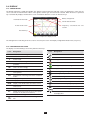
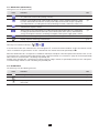
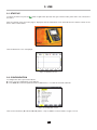
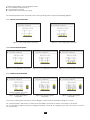
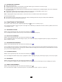
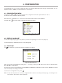
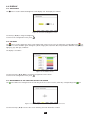
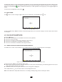
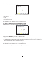
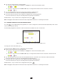
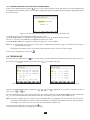
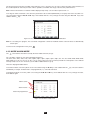
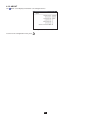
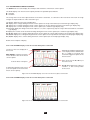
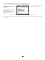
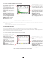
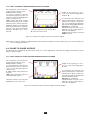
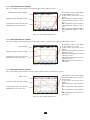
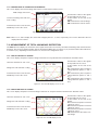
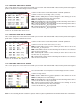
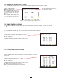
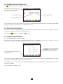
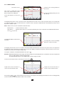
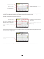
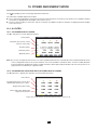
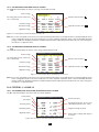
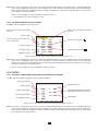
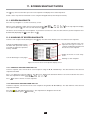
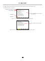
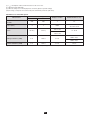
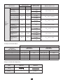
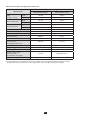
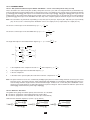
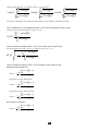
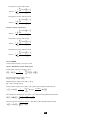
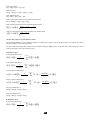
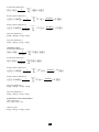
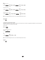
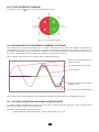
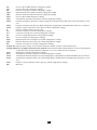
The four last lines involve the recording of the harmonics of U, V, A and S. You can select a range of orders of the harmonics to be recorded (between 0 and 50) for each of these quantities, and within this range, if desired, only odd harmonics. Note: The level of harmonics of order 01 will be displayed only if they concern values expressed in % r. To change an order of harmonic, first select the parameter to be recorded (identified by a red spot), then move the yellow cursor to this figure using the ,, and keys, then validate with the key. Change the value using the and keys, then validate with the key. Figure 33: The second screen of the Trend Mode during modification Note: If a recording is in progress, the associated configuration cannot be modified and the selected values are identified by black spots. To return to the Configuration menu, press . 4.10. MODE ALARM MODE The screen defines the alarms used by the Alarm Mode function (see §7). You can define a alarm on each of the following parameters: Hz, Urms, Vrms, Arms, |Udc|, |Vdc|, |Adc|, |Upk+|, |Vpk+|, |Apk+|, |Upk-|, |Vpk-|, |Apk-|, Ucf, Vcf, Acf, Uthdf, Vthdf, Athdf, Uthdr, Vthdr, Athdr, |P|, |Pdc|, |Q1| or N, D, S, |PF|, |cos Φ|, |tan Φ|, PST, PLT, FHL, FK, Vunb (or Uunb for a three-phase source without neutral), Aunb, U-h, V-h, A-h and |S-h| (see the table of abbreviations in §2.9). There are 40 programmable alarms. To activate an alarm, move the yellow cursor to its number using the , keys, then validate with the key. The active alarm is identified by a red spot. An alarm that is not programmed (“?”) cannot be activated. To program the alarm, move the yellow cursor using the ,, and keys, then validate with the key. Change the value, then validate again. Alarms active. Alarm inactive. Alarm not programmed. Figure 34: The Alarm mode menu 33