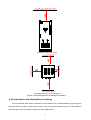
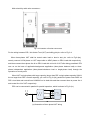
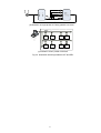
1
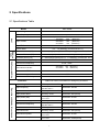
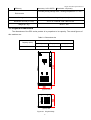
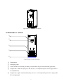
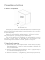
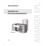
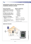
Intepro Systems PEL Series Regenerative AC Load Bank User Manual ©2015 All rights reserved by Intepro Systems Version 1 Version History Version No. V1.0 Release date 4-2015 Writer Description Rev 1 Hardware version applied Intepro Systems provides a full range of technical support for our customers. Customers can contact our offices or customer service centers nearby, or our headquarters. All rights reserved. This manual is subject to change without notice. Safety Precautions Danger Beware o f the high temperature of this equipment. DO NOT open the chassis without technician present or authorization from Intepro Systems. • When the PEL needs to be moved or rewired, please shut down the instrument completely by disconnecting the input power lines and wait at least 20 minutes for the capacitors in the instrument to discharge to prevent electric shock. • In order to ensure the personal safety of users, this series of power products must be grounded before use. • In case of fire, please use dry powder fire extinguishers instead of liquid fire extinguishers to avoid the risk of electric shock. • Liquid or other foreign objects must not be allowed to enter the cabinet of the grid simulator. Attention The application environment and storage methods affect the service life and reliability of the product. Extended use in the following conditions should be avoided: • Ambient high or low temperatures or humidity beyond technical specifications (temperature: -20℃to 40℃; relative humidity: 5% to 95%); • In direct sunlight or exposed to heat sources; • Places susceptible to vibration or collision; • Environments with dust, corrosive substances, salt and combustible gases; Keep the air inlets and outlets unblocked to promote ventilation to avoid a rise in the internal temperature, which may shorten the service life of components, and affect the service life of the product; Grid simulators not in service for a long time should be stored in a dry environment. The temperature range for storage is -40℃to 70℃. To properly protect the equipment, only the personnel of Intepro Systems are allowed to open the front door or side cover. If the quality assurance seal is broken, required services will incur charges and guaranty is void. Danger: conditions that may cause serious equipment damages or human casualties. Attention: Conditions that may cause moderate injuries or damages to equipment. 3 Content Safety Precautions.....................................................................................................................................3 1 Introduction............................................................................................................................................ 6 2 Specifications ........................................................................................................................................ 7 2.1 Specifications table ........................................................................................................................... 7 2.2 Physical dimensions.......................................................................................................................... 8 2.3 Illustration of outline ......................................................................................................................... 9 3 Transportation and Installation .......................................................................................................... 10 3.1 Notes on transportation: ..................................................................................................................10 3.2 Inspection after unpacking..............................................................................................................10 3.3 Requirements of the environment.................. ..................................................................................11 3.4 Instructions and illustrations on wiring.......................... ...................................................................12 3.5 Notes on wiring................................................................................................................................ 15 4 Operation .............................................................................................................................................. 16 4.1 First time start-up............................................................................................................................. 16 4.2 Instructions on user interface software............................................ ................................................ 16 4.2.1 Initializing ................................................................................................................................ 16 4.2.2 User mode ............................................................................................................................... 18 4.3 Application interface.......................................................................................................................... 19 4.3.1 General operation .................................................................................................................... 19 4.3.2 Program operation.................................................................................................................... 21 4.3.3 Single operation (Three-Phase independent settings)............................................................. 21 4.3.4 Measure operation ................................................................................................................... 22 4.3.5 System settings interface ......................................................................................................... 23 4.3.6 Events log ................................................................................................................................. 24 5 Remote Control ...................................................................................................................................... 25 5.1 Communication interface .................................................................................................................. 25 5.1.1 Connection of RS485 ................................................................................................................ 25 5.1.2 Indication of remote control on touch panel .............................................................................. 25 5.2 Operations of remote control on PC .................................................................................................. 26 5.2.1 Software installation .................................................................................................................. 26 5.2.2 Operations on PC ...................................................................................................................... 28 6 Theory of the functions of the machine ............................................................................................... 33 6.1 Block diagram .................................................................................................................................... 33 6.2 Illustration of the block diagram ......................................................................................................... 33 6.3 Construction of main control circuit .................................................................................................... 34 6.4 Characteristics curve of working mode .............................................................................................. 34 4 7 Maintenance .......................................................................................................................................... 37 7.1 Routine maintenance ........................................................................................................................ 37 7.2 Periodic maintenance........................................................................................................................ 38 7.3 Troubleshooting and solutions .......................................................................................................... 38 8 After-sales service ................................................................................................................................ 40 Warranty Card ............................................................................................................................................ 41 5 1 Introduction PEL series regenerative AC load bank is a new generation of bi-directional AC load bank. PEL employs the most advanced PWM rectification (active rectification) technology with four-quadrant operation capability and digital signal processor technology (DSP). It is not only able to simulate different load characteristics including resistance and inductive load, but also feed the energy that helps the industry to save energy and reduce carbon emissions. All necessary protection mechanisms are implemented in the electronic circuitry to quickly detect, execute proper actions immediately and activate necessary alarms. Those protections include overload, over-current, over-voltage and short circuit protection. Laminated bus-bar technology used on the DC bus combined with high efficient IGBT modules further increase the reliability and stability of the machine. This machine can be controlled by either the touch panel installed on it (the local control) or by the communication channels (e.g. RS485) connected to an external computer (the remote control). Either way of control has a user friendly interface which makes the users in controlling and programming this machine much easier than before. The main characteristics of PEL Series Regenerative AC Load Bank are listed as follows: 1) Providing three working modes including constant current, constant resistance and constant power mode, simulating linear load characteristics of power factor 0.3~1.0 (lead/ lag); 2) Adjustable parameters including PF, current, power, resistance and etc.; 3) Suitable for single phase or three phase electric devices burn-in test with supporting 100% unbalance load condition; 4) Energy feeding efficiency to the power grid up to 90%; 5) High power factor in grid connected side up to 0.99; 6) Low current THD in grid connected side (lower than 4%) with low harmonic pollution for grid utility; 7) PEL is expandable for larger capacity for future expansion by parallel connecting multiple units; 8) Standard Modbus protocol and communication interface RS485 are helpful for remote control; 9) 7” Touch panel user friendly interface; 10) Event history records 255 operation events; 11) The laminated busbar structure is used to effectively reduce the inductance of the inverter circuit and improve the reliability of the inverter; 12) Module design is convenient for installation, maintenance and usage; 13) Speed-adjustable fan with lower noise and extended service life; 6 2 Specifications 2.1 Specifications Table PEL-33060 Model Input voltage 120V/208V, 220V/380V, or 277V/480V+/-10% Input frequency 47Hz~63Hz Input Phase / wire 3-phase 4-line +G or 1-phase 2-line+G 120V/208V: 220V/380V: 277V/480V: Input current Input THD (Maximum) (Maximum) (Maximum) ≤4% Power factor Working mode Constant current (CC) 166A 90A 72A 0.3~1.0 (lead/lag) (current≤15A,PF=1) 0~90A(single-phase),PF;0.3~1.0 (lead/lag) (current≤15A, PF=1) Grid Connected Side Constant Resistor (CR) 2.4~44Ω(single-phase),PF;0.3~1.0 (lead/lag) (current≤15A, PF=1) Constant power (CP) 0~20kVA(single-phase),PF;0.3~1.0 (lead/lag) (current≤15A, PF=1) Grid connect voltage 120V/208V, 220V/380V, or 277V/480V+/-10% Grid connect frequency 47Hz~63Hz 120V/208V: 166A (Maximum) 220V/380V: 90A (Maximum) 277V/480V: 72A (Maximum) Grid connect current Grid connect iTHD ≤4% Grid connect power factor ≥0.99 Grid connect efficiency ≥90% Protection Input voltage Protection for under-voltage, under-frequency, over-current, IGBT over-current, over-thermal or emergency shut-down Operation and display of touch panel Resolution: 0.1V Input current Accuracy: 0.2V+0.1%FS Accuracy: 0.01Hz +0.01% FS Accuracy: 0.2A+0.1%FS Input power factor Accuracy: ±0.01 Resolution: 0.01(count) Input power (kW) Accuracy: 0.2kW +0.1%FS Resolution: 0.1kW Input frequency Grid connect voltage Resolution: 0.01Hz Resolution: 0.1A Resolution: 0.1V Grid connect current Accuracy: 0.2V+0.1%FS Accuracy: 0.01Hz +0.01% FS Accuracy: 0.2A+0.1%FS Grid connect PF Accuracy: ±0.01 Resolution: 0.01(count) Grid connect frequency Grid connect power Consumed electricity Accuracy: 0.2kW +0.1%FS Accuracy: 0.2kWh +0.1%FS 7 Resolution: 0.01Hz Resolution: 0.1A Resolution: 0.1kW Resolution: 1kWh(count) Chapter II Product Specifications 5 Efficiency Accuracy: 0.5+0.5%FS Resolution: 1%(count) Humidity during storage: 90%; working temperature: 0℃~45℃ Environment Forced cooling with speed-adjustable fan Cooling method 31.5 x 31.5 x 82.68 / 800 x 800 x 2100 Dimension W*D*H (in / mm) 1675.5 / 760 Weight (lb / kg) 2.2 Physical Dimensions The dimensions of the PEL series product is in proportion to its capacity. The actual figures of this machine are: Table 2-1 Dimensions list Capacity (kVA) 60 Physical dimensions Width(mm) Depth (mm) Height (mm) 800 800 2100 (a) Front view (b) Top view Figure 2-1 Physical body 8 Fig2-2 Side view of the whole machine 2.3 Illustration of outline ① ② ③ ④ ⑤ Fig2-3 Figure of outline illustration ① Touch panel; ② Emergency stop; ③ Circuit breaker on load side (left side), circuit breaker on grid connected side (right side); ④ Copper bar on load side (they are A, N1, B, N2, C, N3 respectively from left to right), while G is on baseboard; ⑤ Copper bar on grid connected side (they are U, V, W, N respectively from left to right), while G is on baseboard; 9 3 Transportation and Installation 3.1 Notes on transportation: Packing machine Fork lift Fig 3-1 Moving with forklift There is space left in the bottom of the cabinet of PEL-33060 that can be used for moving the cabinet with a forklift. Once the cabinet / packing is removed this machine is able to move with its own wheels independently. Because of the heavy weight of this machine, please use a forklift to move the cabinet slowly and with special care. Try to avoid any collisions with other objects. Please keep this machine securely fastened in the truck during transportation to prevent it from collision or tumbling. Although the whole cabinet has an anti-shock design, we still recommend taking extra anti-shock care in the vehicles, especially on a bumpy road. 3.2 Inspection after unpacking Open the wooden cabinet, remove the packing material. Since the machine is pretty heavy, please pay special attention to prevent the machine from tumbling or falling down, while moving it to its final destination; Examine the machine after unpacking it. Check to see if there is any physical damage. If yes, do not install it and call Intepro Systems for help; Examine all the accessories, if anything is missing, please call Intepro Systems for help. 10 3.3 Requirements of the environment Notes on the environment for operating the machine: 1) Ingress protection of the PEL-33060 is IP20, and for indoor use only. Location where the machine installed must have roomy space for air convection. Always keep the inlet and outlet (for air flow) clean and clear; 2) Make sure the location where the machine is installed has strong enough strength and is flat. No shaking or tipping is allowed once installed; 3) All the entrance and exit of the cable wires (for energy in and out) are in the bottom of this machine. It is recommended all cable wires be directed to the duct or gutter on the floor or ground, for easy layout and maintenance; 4) Sufficient space must be kept in surrounding area of the machine to ensure good air convection for heat dissipation (please see Fig. 3-2); 5) Try to avoid any of the following substances in the place where the machine is installed: heavy dust, heavy salt, corrosive chemicals or flammable chemicals. The life and reliability of the machine may be significantly affected; 6) Do not install the machine in a place where temperature or humidity may exceed the allowed limit (see table in Section 2.1). Keep the machine away from a heat source, direct sunlight or flammable vapors; 7) Follow strictly the instructions on wiring and adopt the proper gauge of cable wires, which can ensure both the safety of users and the integrity of the machine. 11 (a) Required space on the top (b) Required space in surrounding area Figure 3-2 Required space surrounding the machine 3.4 Instructions and illustrations on wiring All the electrical cable wires connected to this machine are recommended to go through the reserved ducts or gutters on the floor ground. If not, the space between the feet of this machine and floor ground can be used for laying out those cable wires. 12 Main electricity cable wire connectors : Fig 3-3 Illustration of busbar connectors For the wiring between PEL, Unit Under Test (UUT) and utility grid pls. refer to Fig 3-4. When three-phase UUT shall be tested under load or burn-in test, pls. refer to Fig3-4(a); namely connect U/V/W phase on UUT output side to A/B/C phase on PEL’s load side respectively and then connect three-phase line N on PEL’s load side to line N of UUT after being paralleled. PEL can run on the base of application/assignment application (three-phase balance load) or threephase independent application (three-phase/unbalance load or single-phase load) through the operation on touch panel. When UUT is single-phase with large capacity (larger than PEL’s single phase capacity 20kVA, but no larger than PEL’s overall capacity); pls. refer to Fig 3-4(b), parallel the power lines A/B/C on PEL’s load side and neutral lines N1/N2/N3 on its load side and then connect them to power line L and neutral line N of UUT respectively. PEL can be connected in parallel for parallel operation, which is shown in Fig 3-4(c). (a) Illustration of three phase UUT wiring 13 (b) Illustration of single phase UUT being parallel connected (c) Illustration of PEL parallel connected Fig 3-4 Illustration the wiring between UUT and PEL 14 3.5 Notes on wiring 1) Before connecting the cable wires, make sure all of the wires are not live (zero voltage). Use a voltmeter to check the voltage on all wires; 2) Make sure all the switches on the machine are in the OFF position; 3) Adopt proper gauges for all of the cable wires. Recommendations for those gauges are listed in the following table (Table 3-1): Table 3-1 Gauges recommended Model no. Load side A(phase B and C are the same to Phase A) Current Cable value wiring 90A PEL-33060 2 25mm *1 G N1、N2、N3 Current value Cable wiring Cable wiring 90A 2 25mm *1 10mm2*1 Grid connected side U(Phase V and W is the same to phase U) Current Cable value wiring 90A 25mm2*1 N G Current value Cable wiring Cable wiring 90A 25mm2*1 10mm2*1 The above - referenced table recommends to use multi-core soft copper cable. The user may select for other cables after referring to the input/output current condition; it is advisable to double cable diameter if the length is over 20 meters long for the input or output cable. 4) Connect distribution lines on load side to their corresponding wiring terminals by sequence correctly, while the distribution line on grid connected shall be connected to the connection terminals of electric supply. Note: the relation for wiring (A, B, C and U, V, W generally corresponds to yellow, green and red; N lead generally corresponds to blue, G lead generally corresponds to yellow-green); must not make live operation; must consider remained lead line voltage drop at time of relatively longer input/output lead. 15 4 Operation 4.1 First time start up After finishing making all connections of the load side and grid connected side cable wires, please double check the voltages on all the load terminals and grid connected terminals; the voltages must be within the limits specified in Table 2.1. If not, do not turn on the machine. Recheck everything, fix the problem(s), and redo the procedures. Now users can turn on the input switch (NFB), and the system will start running immediately. The fans inside the machine should be running as well. The touch panel should have the display on. If no abnormal phenomenon is observed, then the machine is now ready for setup and programming. Notes: The sequence of turning on the circuit breakers of the load side and gridconnected side is not strictly required, but the power for PCBA for the internal controller is supplied from the power of grid-connected side. Therefore, the touch panel will be active only when the circuit break on the grid-connected side is turned on. (The voltage on each terminal board shall be confirmed before the circuit breaker on the load side and grid- connected side are turned on). 4.2 Instructions on UI (user interface) software It is the premise for the UI’s giving its best performance to set correct parameters for PEL; as such, a detailed introduction about the starting interface and user mode follows. 4.2.1 Initializing After the PEL is electrified: starting the UI, the first screen displays as in Fig. 4-1: Figure 4-1 UI startup interface 16 The initialization continues as in Fig 4-2: Fig 4-2 Initialization screen 17 4.2.2 User mode Entering the starting menu in the user mode, the screen displays as in Fig. 4-3: Fig 4-3 Starting menu in the user mode 【APP】Enter the menu of setup/programming of the operations; 【SYSTEM】Enter the system setup menu; 【EVENT】Enter the menu of events log. 18 4.3 Application interface There are four tabs in the “Applications” menu. They are “GENERAL”, “PROGAM”, “SINGLE” , and “MEASURE”. Note: The following figures are for illustration of the UI and are general figures only. Actual information in the figures should be obtained from the real display on the touch panel for the specific model of machine. 4.3.1 General operation Fig 4-4 Basic application settings interface 【Mode】 There are three specific working modes: constant current mode, constant resistance mode and constant power mode; 【Load Type】 RL means the PEL can simulate the resistance and inductive load that you can setup the power factor in below from 0.3 to 1.0; 【Para. Setting】Take constant current mode as example, the effective value and PF of current can be set, there are three setting modes for selection: a) Type in the voltage value in the field; in this box; the keyboard will pop up for typing when you click b) Make adjustment through moving it from left or right in the bar c) Click & ; for setting, which is changed by 0.1. 【SETTING】After finishing the typing-in of current and PF, click SETTING Button for sending current and PF value to each module as final target value; 【RUN】After clicking, the device is starting to simulate the load characteristics in accordance with set value; 【STOP】 The device will come into stop after your clicking; 【RESET】Alarm will be cleared after your clicking (Notes: the button will be effective only under fault state.); 19 【 】Indicating light can show the running state of the device: Red: device in halt, Green, device in running. 【 】Showing the current working mode, among which CC, CZ and CP means constant current, constant resistance and constant power respectively; 【 】Showing the load capacity, namely actual value/ maximum simulation value. 20 4.3.2 Program operation Fig 4-5 Program operation interface 【SETTING】 Sending actual running parameters to PEL through touch panel (The current, PF and running interval); 【RUN】After clicking, the device is starting to run in accordance with set value; 【STOP】 The device will come into stop after your clicking; 【RESET】Alarm will be cleared after your clicking (Notes: the button will be active only under fault state.); & Switching the setting interface and preview interface of PROGRAM. 4.3.3 Single operation (Three-Phase independent settings) Fig 4-6 Three-phase independent settings interface 21 【SETTING】 Sends actual running parameters to the power module through the touch panel and sets value of current and PF; 【RUN】After clicking, the device is starting to run in accordance with set value; 【STOP】 The device will come to a stop when selected; 【RESET】Alarm will be cleared after clicking (Notes: the button will be active only under fault state.); 【 】Check box, used to enable or disable corresponding phase; enabled state is white; 4.3.4 Measure operation Fig 4-7 Real-time acquisition interface 【Efficiency】Showing the efficiency of the feeding power to grid; 【Recycle kW.h】Showing the total saving energy in kWh 【Carbon CO2 kg】Showing the Carbon CO2 reduction value from converting the kWh of energy saving. 22 4.3.5 System settings interface The menu for system settings is as in the below picture: Fig 4-8 Menu for system settings 【Time setting】 Current date and time (Date, Hour, minute and second) can be set here; 【Language】Only simplified Chinese, traditional Chinese and English are available now; 【Clear】 The values in box 【Energy-saving】 and【Carbon emission reduction】will be cleared to zero and re-accumulated; 【Maintenance】 Under normal condition, user can not enter this interface for amending system parameters. If it is still needed, pls. contact manufacturer or customer service; 【Back】 Returning to main menu. 23 4.3.6 Events log The events log displays as below: Fig 4-9 Events log display 【Previous】/【Next】:Review all the events on every page; 【Clear】:Clear all the events in this log; 【Back】:Return to the main menu. 24 5 Remote Control 5.1 Communication interface RS485 is a standard communication connector for this series of machines. 5.1.1 Connector of RS485 Open the front cover, the RS485 connector is located in the back of the touch panel computer, shown in the figure below: a) Touch panel backware interface diagram RS485 D-Sub 9 Connector Pin Definition Pin Number Signal PC 1 Rx- (B) RS485B 5 GND Ground 6 Rx- (A) RS485A b) RS485 interface descriptions Fig. 5-1 RS485 interface schematic diagram 5.1.2 Indication of remote control on touch panel While the communication channel of this machine is successfully linked with other computing equipment, there will be an indication text “Remoting …” shown on the screen, as in the below Figure 5.2: 25 Fig 5-2 “Remoting…” shown on screen 5.2 Operations of remote control on PC 5.2.1 Software installation Open the software CD package, install the software by executing the setup.exe on the CD, as shown in the below picture. Fig 5-3 Software installation kit on the CD 26 Operating systems supported: Windows XP、WIN7、WIN8. Fig 5-4 First step of the installation Fig 5-5 Second step of the installation Choose the language for use in the software. It is recommended to install on a non-system disk drive (e.g. D:\ disk). 27 Fig 5-6 Third step of the installation Fig 5-7 Shortcut on the PC desktop after successful installation 5.2.2 Operations on PC 5.2.2.1 Main remote interface (not connected) Double click the shortcut (as shown in Fig. 5-7) on the desktop, then enter the system main menu (as shown in Fig. 5-8). Before communication channels are successfully linked, all the major action buttons such as【Run】、【Stop】、【Reset】and all the drop down menus such as “General operations”, “Output monitoring”, “Specific applications” are all grayed out (and cannot function). 28 Fig 5-8 Remote-control interface - not connected 5.2.2.2 Communication setting interface Click【System】in the menu then click COMM Setting, communication settings interface will appear as shown in Fig 5-9. Communication parameter shall be set as follows: The address of the device: 7(default value) Communication mode: RS485 (default value) Serial port no.: Choose in accordance with the serial port of actually-adopted PC. Fig 5-9 Communication settings interface Click the 【Link】button after set-up completes, and if the configuration is correct. Serial port is open and device is connected will be shown in the Link Status. 5.2.2.3 Main remote interface (Connected) After successful connection to PEL, the main interface will be unlocked as shown in Fig 5-10: 29 Fig 5-10 Remote-control main interface (already connected) Fig 5-10 is the default interface of general application and three-phase independent, among which there is a check box before three-phase independent setting. If it is selected, general application interface will be switched to three-phase interface; if not, it will be general application interface. 5.2.2.4 General application (Three-phase) interface (working mode settings) Click【System】 in the menu as shown in Fig 5-11, choose 【Work Mode】in pull-down menu, the working mode of PEL can be selected here. After choosing the working mode successfully such as constant current mode, the effective value and PF value of the current you would like to simulate can be chosen. Fig 5-11 Basic application (three-phase independent) interface 30 5.2.2.5 Program application interface In general application interface click【Program】 in the menu and enter program application interface as shown in Fig 5-12. (a) Task application settings interface (b) Preview Fig of task application settings interface Fig 5-12 Task application interface Set up Start No., Last No. and cycles times. A maximum of 24 groups and 255 cycle times can be set up; After the user sets data successfully, you can click【Settings】for downloading data; 31 Click 【Preview】to review operation schematic diagram about set data; 【 】State indicating light: Red means the device is in stop status, while green means the device is in operation state; 【Running】After clicking, the device is starting to run in accordance with set values; 【Stop】 The device will come into stop after your clicking; 【Reset】Alarm will be cleared after your clicking. 5.2.2.6 Real-time Monitoring interface In the general application interface and program application interface, click【Monitor】menu and enter real-time monitoring interface as shown in Fig 5-1: Fig 5-13 Real-time remote acquisition interface Whether to load data or save the log is available for selection; Acquisition can be controlled or halted. Notes 1: Real-time acquisition can be entered only under running state. Notes 2: After user connects remote control successfully, it can be unlocked through pressing 【Local】. 32 6 Theory of the functions of machine 6.1 Block diagram Functional blocks (from input to output) of the PEL series regenerative AC load bank are shown in Figure 6-1: Utility Grid Input Unit Under Circuit Test (UUT) Breaker Regulated Inductance Sampling for load side voltage/current Input Simulation Inverter DC Bus Output Inverter Circuit Circuit DC voltage IGBT drive and OC sampling IGBT drive and OC sampling sampling Utility Grid Output Output Circuit Breaker Transformer Filter Sampling for Grid connected side voltage /current Main control circuit Power Touch panel Over/undervoltage testing EPO testing Over/underfrequency testing Overcurrent testing Overtemperature testing Fig 6-1 Functional block diagram 6.2 Illustration of the block diagram 1) Utility Grid: Utility grid shall be connected to input side of unit under test (UUT) 2) Unit Under Test (UUT): UUT shall be connected to the load terminal of PEL device 3) Input circuit breaker: Turn on/off between the output side of UUT and the input side of PEL. 4) Regulated Inductance: Energy buffering for the input side of PEL and output side of UUT 5) Input Simulation Inverter Circuit: Simulating load characteristic in each phase 6) DC Bus: DC Bus 7) Output Inverter Circuit: Inverting energy from DC to AC and synchronizing with grid. 8) Output Transformer Filter: Energy buffering for the output converter and utility grid 9) Output circuit breaker: Turn on/off between the output side of PEL and the utility grid. 10) Sampling for load side voltage/frequency: Measuring input voltage and current for control board calculation on PEL. 33 ) I BT drive and OC sampling: Drive signal to I BT and sensing for over current. ) DC voltage sampling: Measuring the voltage of DC bus for control PCB. ) I BT drive and OC sampling: Drive signal to I BT and sensing for over current on grid connected side. ) Sampling for rid Connected oltage and Current: Measuring the voltage and current on grid connected side for control calculation. ) Utility rid power: All supply powers on PCB from utility grid ) Main control circuit: Control algorithm main digital signal processor in PEL ) Touch panel: Operation and control on human machine interface. ) EPO: Emergency Power Off. ) Over/Under voltage test: Conducting over/under voltage test on load and grid connected side. ) Over/Under frequency test: Conducting over/under frequency test on load and grid connected side. 21) Over-current test: Conducting over-current test on load and grid connected side. 22) Over-temperature test: Testing the internal temperature of IGBT. 6.3 Construction of main control circuit The main control circuit is mainly divided into the three parts, namely protection sampling module, main control module and display control module. The relationships between these three parts are shown in Fig. 6-2. Protection sampling module Main control module Display control module Fig 6-2 Block diagram of control parts 6.4 Characteristics curve of working mode The application types of the PEL-series Regenerative AC Load Bank can be classified into general application, program application and three-phase independent (single) application. Under the general application, three-phase balance load can be simulated and can be programmed for 24 groups with 255 cycle times Under a three-phase independent (single) application, one, two or three of the three phases can be run at the same time. All three types include the three working modes: constant current mode (CC), constant resistant mode (CZ) and constant power mode (CP). 34 Their respective working power characteristics curves are shown as Figure 6-3, Figure 6-4 and Figure 6-5. Fig 6-3 Constant current (CC) mode Fig 6-4 Constant resistance (CZ) mode 35 Fig 6-5 Constant power (CP) mode 36 7 Maintenance Extreme temperature, high humidity, heavy dust, chemical pollution and physical vibration all could impose negative impacts on the life and reliability of this machine. The natural aging of all of the electrical and mechanical components would also cause the machine to be susceptable to all kinds of faults. Therefore, routine and periodic maintenance are necessary and key to the reliability of this machine over time. Only authorized and trained technical professionals are allowed to carry out the maintenance on this machine. 7.1 Routine maintenance First, the daily operating environment must comply with the requirements stated in this user manual. Routine inspection of the environment and the machine should be done on a regular basis. All the environmental data, the operating status and the parameters set in the machine should be recorded as well. It is best to have a detailed and accurate “machine usage log file” for time reference and maintenance. Abnormal issues on the machine can be detected by the routine inspection and maintenance. Once observed, the root cause should be identified and the problem resolved immediately. Call Intepro Systems if you are not able to identify the cause, or not able to resolve the problem. The earlier we can solve the problems, the longer the life of the machine. Items to be checked as part of routine maintenance are listed in Table 7-1. Table 7-1 List of checking items on routine maintenance Object to check Environ -ment Inspection details Checking items (1). Temperature and humidity (2). Dust, moisture and water leakage (drop on the machine). (3).Abnormal Chemical vapor When to check Methods to check (1).Thermometer, Hygrometer Anytime (2). Visual inspection (3). Visual inspection and smell 37 Criteria (1). Ambient temperature must < 40˚C, or maximum load need to be de-rated. Humidity should be comply with the spec requirements. (2). Little dust, no condensing, no water drop on the machine. (3). No abnormal smell, no abnormal color in the air. ⑴ No shock, no vibration ⑵ Fan operating: check to see if speed This machine ⑴ Shock, vibration ⑵ Heat dissipation Anytime ⑶ Acoustic noise ⑴ Visual inspection, and air flow volume OK or not. Measure the temperature on the surface of the sense of moving. ⑵ Thermometer ⑶ Sense of hearing ⑴ ⑵ Output ⑶ status ⑷ Input / Input voltage Output voltage Output current Temperature inside the machine ⑴ Voltmeter ⑵ Voltmeter Anytime ⑶ Ammeter ⑷ Thermometer enclosure; they should not have more than 30˚C temperature rise. ⑶ No abnormal acoustic noise. ⑴ within the spec limit ⑵ within the spec limit ⑶ within the spec limit ⑷ Temperature rise < 40˚C 7.2 Periodic maintenance Depending on the usage of this machine and the environment where it works,a periodic maintenance can be carried out once every 3~6 months. Maintenance task: Screen filter for the air inlet should be detached and washed clean。 Note:Open the front door of the enclosure to detach and re-install the screen filter, there is a cover in front of the screen filter, it needs to be removed before the filter can be accessed. 7.3 Trouble Shooting and Solutions Before seeking service, users can first do a self-inspection and record fault phenomena in details according to the tips in this section. When you need to seek service, please contact Intepro Systems. 38 Table 7-2 Alarm content & solutions Fault Type Grid frequency over limit Inverter NPLL Possible Causes of Faults Grid frequency over the range of device supported The phase loop of Inverter not locked Solutions Check frequency of grid voltage Check grid voltage Grid voltage too low Input frequency over limit Rectifier NPLL Grid voltage lower than lower limit value Input frequency over the range of device supported The phase loop of Rectifier not locked Check grid voltage Check frequency of input voltage Check input voltage Input voltage too low Input voltage lower than lower limit value Check input voltage DC bus error DC bus voltage is abnormal(too low or too high) EPO fault The internal temperature of device too high Emergency stop button is pressed The working status of fan is abnormal Check system parameter After troubleshooting the system, Popup EPO button Check fan Input voltage too high Input voltage higher than upper limit value Check input voltage Input current over limit Input current higher than upper limit value Check system parameter Grid voltage too high Grid voltage higher than upper limit value Feedback current Feedback current higher than upper limit value over limit DC bus too high Load side IGBT-OC1 Load side IGBT-OC 2 Load side IGBT-OC 3 Load side IGBT-OC 4 Grid connected side IGBT-OC 1 Grid connected side IGBT-OC 2 Grid connected side IGBT-OC 3 Grid connected side IGBT-OC 4 DC bus voltage higher than upper limit value IGBT of line L upper bridge arm on load side damaged IGBT of line L lower bridge arm on load side damaged IGBT of line N upper bridge arm on load side damaged IGBT of line N lower bridge arm on load side damaged IGBT of line L upper bridge arm on grid connected side damaged IGBT of line L lower bridge arm on grid connected side damaged IGBT of line N upper bridge arm on grid connected side damaged IGBT of line N lower bridge arm on grid connected side damaged 39 Check grid voltage Check system parameter Check DC Bus Check and replace IGBT Check and replace IGBT Check and replace IGBT Check and replace IGBT Check and replace IGBT Check and replace IGBT Check and replace IGBT Check and replace IGBT 8 After-Sales Service Intepro Systems provides a full range of technical support to customers. Customers are encouraged to contact our branch office or our technical personnel when you have purchased our product. For the details of warranty, please refer to the terms of warranty. We provide paid customization service packages at different levels, including fast response, preventive maintenance, and warranty renewal service. Please contact the local service centers of our company. • Service Telephone USA: +1.714.953.2686 UK/Europe: +44.1251.875600 Asia: +86.755.86500020 • On-line technical service: www.InteproATE.com • Intepro Systems America, LP 14712-A Franklin Avenue Tustin, CA 92780 USA Tel: +1.714.953.2686 Fax: +1.714.673.6567 40 Quality Service Innovation Warranty Card Dear , Thanks for your support and patronage. This card is to ensure that in case the grid simulators you have purchased (model: ____________, serial number: fail in normal conditions of use within a year because of the process error or component deterioration, Intepro Systems, LP. will have responsibility to provide after-sales service for free. Please note: The machine is required to be installed and used properly. Do not modify the structure, circuit or component. 1. If the machine has faults, please call us or pack the machine properly and indicate the faults before sending back to our company. We will serve you as soon as possible. 2. If the warranty period expires, and the customer keeps the card, we will charge a reasonable fee after the completion of repair. Attn: Date: 41