1
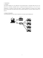
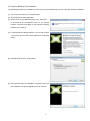
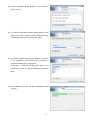
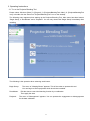
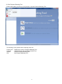
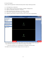
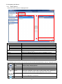
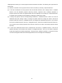
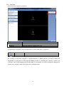
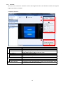
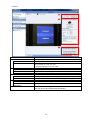
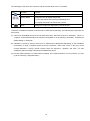
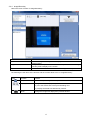
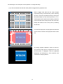
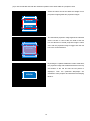
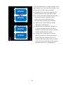
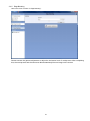
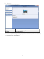
Projector Blending Tool Ver.1.00 User’s Manual Hitachi Maxell, Ltd. 1 Contents 1. Introduction .................................................................................................................................................... 3 1.1 Features ................................................................................................................................................... 3 1.2 System Configuration .............................................................................................................................. 3 2. Installation ..................................................................................................................................................... 4 2.1 System Requirements ............................................................................................................................. 4 2.2 Projector Blending Tool Installation ......................................................................................................... 5 3. Operating Instructions ................................................................................................................................... 8 3.1 Start-up Projector Blending Tool .............................................................................................................. 8 3.2 Quit Projector Blending Tool .................................................................................................................... 9 3.3 Control Procedure ................................................................................................................................. 10 3.4 Navigating the Menus ............................................................................................................................ 11 3.4.1 Warping Boxes ................................................................................................................................. 11 3.4.2 Projectors ......................................................................................................................................... 13 3.4.3 Cameras........................................................................................................................................... 14 3.4.4 Image Boundary............................................................................................................................... 17 3.4.5 Edge Blending .................................................................................................................................. 21 3.4.6 Management .................................................................................................................................... 22 4. Operating Suggestions................................................................................................................................ 23 ・ Microsoft, Windows and .NET Framework is the registered trademark of Corporation in US other countries. ・ Pentium is the registered trademark of Intel Corporation in US and other countries. ・ All other trademarks are the property of their respected owners. Warning ・ This software is free via download. The manufacturer has no responsibility for any errors that may occur while using this software. ・ This software, or any product used with this software may not be used for any act which obstructs the Maintenance of the International Peace and Safety. ・ This software, or any product used with this software may not be used for any act which obstructs the Maintenance of the International Peace and Safety. If this software is to be exported, please confirm the regulation of foreign exchange law, foreign trade law, US export administration regulations and the laws and regulations of the interested state and take the necessary procedures. 2 1. Introduction 1.1 Features The Projector Blending Tool is the application to blend images based on a detected image using up to four projectors by connecting a supported camera. It supports the blending of projectors in a 1x4, 4x1, 2x2, etc configuration. It is possible to overlap each image in a blended configuration by connecting a PC to multiple projectors which support the blending function and by sending a Warpmap, a correction of data for blending, to a projector. 1.2 System Configuration The following diagram shows the system configuration for using the Projector Blending Tool. Camera PC Projector USB Projector LAN LAN HUB Projector Projector 3 2. Installation 2.1 System Requirements The following are the requirements of the supported hardware and software to use the Projector Blending Tool. (1) Operating System Windows XP Home Edition Windows XP Professional Windows Vista Home Basic Windows Vista Home Premium Windows Vista Business Windows Vista Enterprise Windows Vista Ultimate Windows 7 Home Basic Windows 7 Home Premium Windows 7 Professional Windows 7 Enterprise Windows 7 Ultimate Windows 8 Windows 8 Pro Windows 8 Enterprise (2) Display XGA 1024 x 768 or higher、65,536-colors or higher (3) CPU Pentium 4 (2.8 GHz or higher) (4) Memory 1GB or higher (5) Hard Disc Minimum 150 MB free space for installation (6) Wired or Wireless LAN 4 2.2 Projector Blending Tool Installation The following describes the installation process for the Projector Blending Tool to the PC with Windows7 installed. (1) Turn on the PC and log on as Administrator. (2) Shut down all the other application. (3) Double click “ProjectorBlendingTool_v1.00_Setup.exe”. In case DirectX is not installed to your PC, you need to install it. Therefore press [OK]. In case DirectX is already installed, go to step (7). (4) License agreement dialog appears. If you accept it, select “I accept the terms of the license agreement” and press [Next]. (5) Install DirectX Runtime. Press [Next]. (6) Press [Finish] when the installation completes. After that, the installation of Projector Blending Tool will continue. 5 (7) License agreement dialog appears. If you accept it, Press “I Agree”. (8) The Choose Destination Location dialog appears. Click [Next]. If you want to install to another destination folder, click [Browse] and select the destination folder. (9) The Select Program Folder diagram appears. The name to be registered in the [Start] menu’s [Program] is “Projector Blending Tool”. Click [Next]. At this time, in case the needed device driver is not installed to your PC, you will be requested to install the driver. (10) The installation process will start automatically after step (9). 6 (11) “Completing the ProjectorBlendingTool Setup Wizard” dialog will be shown when the installation is completed. Click [Finish] to complete the installation. After the installation is completed properly, the folder registered in the step (9) will appear in [Start] menu [All programs]. “ProjectorBlendingTool” will appear if the installation was successful. The shortcut for “Projector Blending Tool” will also be set on the desktop. 7 3. Operating Instructions 3.1 To run the Projector Blending Tool Please select Windows [Start] [Program] [ProjectorBlendingTool folder] [ProjectorBlendingTool icon] or double click the shortcut of “ProjectorBlendingTool” icon on the desktop. The following menu appears when starting up the Projector Blending Tool. Main menu has three buttons “Begin Setup”, a “Recalibrate” and a “Playback". You can only choose the "Begin Setup” immediately after installing. The following is the operation when selecting each button. Begin Setup: The menu of “Warping Boxes” appears. This is first action to operate this tool. You can begin to select projectors which should be controlled. Recalibrate: Edit the data to control the blending function by re-calibration. Then apply the data. Playback: The menu of “Management” appears. You can operate the engagement or disengagement for the data calibrated. 8 3.2 Quit Projector Blending Tool Please select [Menu] [Exit] or click [x] button to quit the Projector Blending Tool. The following is the operation when selecting each icon. Product Info: UI Scale: Restart: Exit: Displays the version of Projector Blending Tool. Change the size of the character and the icon. Re-boot Projector Blending Tool. Quit Projector Blending Tool. 9 3.3 Control Procedure Please operate this application to initiate the blending function using the following procedure. (1) Click “Begin Setup” in Main Menu. (2) Assign IP address of projectors which should be controlled in “Warping Boxes”. (3) Select the configuration of projectors in “Projectors”. (4) Make a blending data after calibrating for your camera in “Cameras”. (5) Set the area for displaying the projected image in “Image Boundary”. (6) Update the gamma setting to adjust the luminance level of overlap area in “Edge Blending”. You can change the menu by clicking the “Next” button or the “Previous” button in bottom of the menu. e.g.) In the case of “Projectors”, go to “Cameras” by clicking the “Next” button. In the case of “Projectors”, go to “Warping Boxes” by clicking the “Previous” button. The details for each function and the meaning of menu are in section 3.4. 10 3.4 Navigating the Menus 3.4.1 Warping Boxes Here is the menu content of “Warping Boxes”. (1) (2) (3) (4) Content Output Resolution XGA WXGA HD WUXGA Available Devices Assign Assign All Assigned Devices Remove Remove All Add IP address manually Function Overview Select the output resolution Select in case the resolution is XGA (1024 x 768) Select in case the resolution is WXGA (1280 x 800) Select in case the resolution is HD (1920 x 1080) Select in case the resolution is WUXGA (1920 x1200) Show the projectors which are possible to control by the projector automatic discovery function Select an IP address of the projector which is available to control Select all IP addresses of projectors which are available to control Show IP addresses selected Remove an IP address of the projector selected from Assigned Devices Remove all IP addresses of projectors selected from Assigned Devices Enter an IP address manually The following are the names of each function and the content associated with the icons in “Assigned Devices”. Icon Function Content Help Show the help of Warping Boxes. Rediscover Execute the projector automatic discovery function. Connect Connect with the projector via LAN. Verify Verify the connection. Once show a blank image when verifying the connection and then show the input image after a few seconds. Change Change the order to control assigned projectors. This order corresponds with the configuration in Projectors. Add Add IP address manually. 11 “Warping Boxes” allows you to select projectors which should be controlled. The following is the procedure for this function. (1) Select the resolution of the projectors which will be controlled, by selecting “Output Resolution”. (2) To find the IP addresses of the projectors with the selected resolution and to display them in “Available Devices” use the automatic projector discovery function. Projectors with a different resolution or projectors that do not match the applied model will not be displayed. If the setting of “Output Resolution” is changed, the information will be updated by clicking the “Rediscover” button. (3) To assign the projector with the corresponding IP address in “Available Devices”, select one of the IP addresses and push “Assign” button. To assign all, please select the “Assign All” button, and all the projectors which are shown in “Available Devices” are assigned as operational projectors. If you need to remove the IP address which is shown in “Assigned Devices”, select the IP address and select “Remove”. If you need to remove all the projectors then select the “Remove All” button, and all the projectors will be removed. (4) In case the IP addresses which will be controlled are not found in “Available Devices”, enter the IP address manually in the window at the bottom of “Assigned Devices”. Then you can select a projector model that supports the blending application. Projectors with a different resolution or projectors that do not match the applied model will not be displayed and an error message will be displayed. 12 3.4.2 Projectors Here is the menu content of “Projectors”. Content Size of projector array Rows Columns Function Overview Defines the number of projectors to connect and the configuration. Select the number of rows from 1 to 4. Select the number of columns from 1 to 4. The following are the names of the function and the content of the icons in “Projectors”. Icon Function Content Help Show the help of “Projectors”. On the basis of the number assigned in “Assigned Devices” of “Warping Boxes”, you have to define the configuration of projectors for executing the blending function by selecting the number of “Rows” and “Columns”. If the number displayed and actual location is not matched, you need to change the setting of the number using “Change” button after going back to “Warping Boxes”. 13 3.4.3 Cameras Here is the menu content for “Cameras”. Each of the images below show the difference between the Logitech (Logicool) and Canon cameras. < Logitech (Logicool) > (1) (2) (3) Content Type of Camera Automatic Logitech Camera Settings Exposure Gain Focus Tools Auto-Tune Show Pattern Begin Data Collection Function Overview Select the type of camera to connect. Connect automatically if the acceptable camera is connected. Use Logitech (Logicool) camera. HD Pro Webcam C910 / HD Pro Webcam C920 Calibrate the camera manually. Adjust the exposure time. Adjust the luminance gain. Adjust the focus. Set up the other functions. Calibrate the camera automatically. Change the Focus Pattern and the Desktop (Input Image). On the basis of the image detected by camera, gets the information from the camera and creates data for blending. 14 < Canon > (1) (2) (3) Content Type of Camera Automatic Canon Camera Settings Exposure Aperture ISO Tools Auto-Tune Show Pattern Options Continuous capture mode Take picture after manual adjustment Begin Data Collection Function Overview Select the type of camera to connect. Connect automatically if the acceptable camera is connected. Use Canon Digital SLR camera. [U.S ] Canon T1i / T2i / T3 / T3i [ JPN ] EOS Kiss X3 / X4 / X5 / X6i Calibrate the camera manually. Adjust the exposure time. Adjust the aperture setting. Adjust the ISO setting. Set up the other functions. Calibrate the camera automatically. Change the Focus Pattern and the Desktop (Input Image). Select the optional settings. Enable the continuous capture mode. Enable to take a picture after manual adjustment. On the basis of the image detected by camera, gets the information from the camera and creates data for blending. 15 The following are the name of the function and the content about icons in “Cameras”. Icon Function Content Help Show the help of “Cameras”. Display Mode Change the way to display the preview. (1) Fit to the window size of Projector Blending Tool. (2) Display the actual size detected by camera. Zoom Change the image size displayed in preview window. “Cameras” is intended to calibrate a camera and to create data for blending. The following is the procedure for this function. (1) Connect an acceptable camera to PC via USB. At this time, select the mode from “Automatic”, “Canon” or “Logitech”. Detect automatically if the camera is acceptable or not by selecting “Automatic”. Therefore the default setting is “Automatic”. (2) Calibrate a camera by clicking “Auto-Tune” to optimize their adjustments depending on the installation environment. If using a Logitech camera, there are “Exposure”, “Gain” and “Focus” in the menu of the camera calibration. If using a Canon camera, there are “Exposure”, “Aperture” and “ISO”. It is also available to adjust manually using the three adjustments above. (3) Execute “Data Collection” to create data for blending. If the “Data Collection” is not successful, you can’t go to the next step; “Image Boundary”. 16 3.4.4 Image Boundary Here is the menu content of “Image Boundary”. Content Reset Point Locations Toggle Preview Update Calibration Function Overview Reset the image boundary area to display on the screen back to the default position. Change the mesh pattern and the outline box pattern to define image boundary area to display on the screen. Create data which includes information of the image boundary area. The following are the name of the function and the content about icons in “Image Boundary”. Icon Function Content Help Show the help of “Image Boundary”. Display Mode Change the way to display the preview. (3) Fit to the window size of Projector Blending Tool. (4) Display the actual size detected by camera. Zoom Change the image size displayed in preview window. 17 The following are two examples for the operation of “Image Boundary”. (1) In case a selected area with the mesh pattern is bigger than a projection area. 1 2 Select a bigger area than the two center images projected by doing vertical blending. When selecting the area, choose the operational point by clicking the left mouse button on the corner point from 1 to 4. HITACHI Then drag the corner point to the location you want in preview window while holding the left click. After that, HITACHI identify the location of the corner point by releasing the left click. 3 4 1 2 The theoretical projection image against the selected area is red box. But the actual projection area is blue box. HITACHI HITACHI 3 4 By clicking “Update Calibration” button at this time, the projected image with the clipped blue box, see the left picture, is displayed. Then the optimized Warpmaps are delivered to each projector and HITACHI transferred to Warping Mode 3. 18 (2) In case a selected area with the outline box pattern is the same width as a projection area. Select the same area as the width and height of one projection image against two projection images. 1 HITACHI 2 HITACHI 3 4 The theoretical projection image against the selected area is red box. In case of this, the width of the red box and blue box of actual projection image is same 1 HITACHI 2 size. And the projection image is bigger than the red box in the vertical direction. HITACHI HITACHI 3 4 By clicking the “Update Calibration” button at that time, the projection image which added the black on the top and bottom of the red box like the left picture is displayed. Then the optimized Warpmaps are delivered to each projector and transferred to Warping HITACHI Mode 3. 19 In case the selected area in “Image Boundary” has a large distortion such as an abnormal rectangle, it will cause image crush. Here are two examples. HITACHI 1 3 a) The selected area is extremely smaller than the 2 4 projected image as shown in left upper picture. b) No.1 corner point locates to right side against No.2 HITACHI corner point as shown in left bottom picture. If image crush occurs, please shut off the current processing according to the following. (1) 2 1 Shut off the current processing by clicking “Disengage” in Management (2) If image crush is resolved by the operation of (1), select the image boundary area which is HITACHI available to execute normal collection. After that, click the “Update Calibration” again. (3) HITACHI 3 If image crush is not resolved, you have to turn off the projectors to be controlled using a remote control or the keypad. Then, turn on 4 projectors after finishing the period of cool down. If each projector runs normally, please verify the connection with the PC in “Warping Boxes”. 20 3.4.5 Edge Blending Here is the menu content of “Edge Blending”. Please execute the gamma adjustment to adjust the luminance level of overlap area. After completing this, the overlap area and the other area blend seamlessly like one image on the screen. 21 3.4.6 Management Here is the menu content of “Management”. Content Engage Disengage Recalibrate Function Overview Execute the blending processing. Stop the blending processing. Re-run Data Calibration. If you have to stop the blending processing, it is possible to control blending in this menu. Additionally you can also re-run the “Data Calibration”. 22 4. Operating Suggestions The following is the operating suggestion using this application. - Please use this application when projector is turned ON. - This application may not function well when there is firewall software, other than Windows Firewall, installed to the PC. Please register this application as exceptional or disable the firewall software by referring to the manual. - The connection may fail if the user goes through the connection procedure of the Live Viewer application during the usage of this application. - The collected data is delivered to Warping mode 3 in this application. - If you select Warping mode 3 without displaying the blended image, the OSD menu will not be displayed. To disable the Warping mode, push the Keystone button of the remote control for a 3-5 seconds or selecting "Disengage" in the"Management" tab. This will enable the Keystone mode and the OSD menu will be displayed. - .Net Framework 3.5 supported by Microsoft needs to be installed to your PC when you use this application. Installing the .NET Framework 3.5 will be required when installing this application in case there is not the software. Please install the Microsoft .NET Framework 3.5 by downloading via Internet at that time or executing the software which was downloaded preliminarily. 23