1
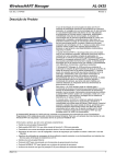
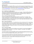
WirelessHART Manager Doc. Code: CE104635 AL-2435 Revision: A Product Description The use of wireless data communication technologies in automation systems is a trend in expansion growing. There are several use advantages of wireless technology and their dissemination is above their real potential, specially because there are doubts about security, performance and reliability in this kind of communication. The wireless communication solutions reduce significantly the cabling, installation and commissioning costs. Furthermore, it is also extended to the maintenance phase because this kind of communication permits the access to data that cannot be access using wire technologies. The access to these data and their further analysis can prevent unnecessary process interruptions, which increases the plant availability, productivity and security. The standard WirelessHART is ideal technology to wireless communication for industrial systems, offering a secure and reliable way with a complete range of applications in process monitoring and control and asset management. Based on the HART well-known protocol, WirelessHART allows the users to use the benefits of the wireless technology in fast and easy so that to maintain the compatibility with existing devices, tools and systems. WirelessHART Manager AL-2435 allows that the automation systems and assets management stations are connected to wireless sensor networks of the WirelessHART standard. The product provides a solution that allows the industrial plants, such as metallurgy, sanitation and oil and gas to be monitored for the detection and prediction of faults, in a way to increase the assets availability and minimize the shutdown time. The addition of wireless instrumentation to industrial plants allows monitoring the variables, which had not been measured before, by dedicated systems, or systems integrated in the assets management tools. Furthermore, AL-2435 can also be used to monitor the different tools, which enable the connection through WirelessHART, such as temperature, pressure, level and corrosion transmitters. Conventional tools that use the HART standard can also be connected to the network using adaptors, which allows mounting the telemetry system of industrial park. The connection between AL-2435 and the system is performed by means of an Ethernet interface available on the equipment, allowing connectivity with other field networks. Thus, it is possible to expand the Altus solution to the Assets Management, permitting that the same client tool has an access to the assets data connected either to the wired networks or to the wireless networks. Such access is provided by encapsulating the HART messages exchanged between AL-2435 and the instruments. WirelessHART Manager AL-2435 can be connected to automation equipment, such as Programmable Controllers, responsible for the plant process control. For this purpose, the WirelessHART network tools variables are mapped and accessed through the MODBUS TCP protocol. The photo illustrates the product, whose main features are: WirelessHART communication standard IEEE 802.15.4 radio standard, which uses channels about 2.4 GHz for operation Coexistence with other technologies operating in and out the same spectral range Network security using cryptography and security keys that impede the access to the network without using them Algorithm for messages publishing in an efficient way, aiming maximizing the use of the battery devices and or techniques for wireless devices feeding Ethernet communication interface HART Protocol for communication with asset management tools MODBUS TCP Protocol for connection to the process control system Aluminum casing with protection degree IP 65 for outdoor use Removable antenna with possibility to use an external antenna WirelessHART network with capacity up to 50 nodes Configuration and monitoring through an integrated web server Monitoring of the network typology by means of a graphic interface with all devices information Feeding option using PoE (Power over Ethernet) by means of external adaptors or injectors Real time clock with synchronization through NTP protocol Altus S. A. 1 WirelessHART Manager Doc. Code: CE104635 AL-2435 Revision: A Ordering Information Included Items The product package contains the following items: AL-2435 Antenna Power supply connector Ethernet connector Installation Guide Product Code The following code shall be used to purchase the product: Code Name AL-2435 WirelessHART Manager Related Products The following products shall be purchased separately, whenever necessary: Altus S. A. Code Name AL-1535 Power supply source 24 Vdc 2,5 A AL-1536 Power supply source 24 Vdc 5 A 2 WirelessHART Manager AL-2435 Doc. Code: CE104635 Revision: A Features General Features AL-2435 Type of Module WirelessHART Manager Casing Material Aluminum Ethernet Interface RJ45 (10/100Base-TX) Rated power supply voltage 24 Vdc Power supply voltage 19.5 to 30 Vdc Maximum current consumption 200 mA Dissipated power 4,8 W Power over Ethernet Yes, 24 Vdc Maximum number of nodes on the wireless network 50 nodes Real time clock Yes WirelessHART Protocol version 7.1 Ethernet application protocols HART and MODBUS TCP Time synchronization Yes, through NTP protocol Configuration Through an integrated web server Diagnosis Through an integrated web server Operation temperature 0 to 60 oC Storage temperature -20 to 70 oC Operation humidity 0 to 95 % (no condensation) Protection index IP 65 Weight 2.230 kg Weight with package 2.600 kg Dimensions 409,0 x 225,0 x 68,3 mm (height x width x depth) Normas atendidas - IEC 61131-2:2007, chapter 8 and 11 - ETSI EN 301 489-1 V1.9.2, chapter 8 and 9 - ETSI EN 300 328 V1.8.1, chapter 4.3.2 - ETSI EN 301 489-17 V2.1.1, chapter 6 - ANATEL resolution nº 506, section IX - ANATEL resolution nº 442 - CE, Eletromagnetic Compatibility (EMC), Low-Voltage Directive – LVD) and Radio equipment and Telecommunications Terminal Equipment Directive (R&TTE). - ANATEL, technical requirements and trial procedures applied to product certification for telecommunication Category II. Notes Ethernet Interface: It is recommended the use of Category 6 cable (CAT6). Consumption: Maximum consumption considering power supply voltage of 24 Vdc. Power: Power considering power supply voltage of 24 Vdc. Power over Ethernet: The power supply voltage of the Power over Ethernet (PoE) is the same as the rated voltage. In order to use the PoE, it is necessary to use external to the product injectors or adaptors. For details about the connection diagram in these cases, see section Installation Using Power over Ethernet. Weight: Approximate weight, considering AL-2435 with the supply and Ethernet connectors, as well as the mounted antenna. Dimensions: These dimensions consider the whole ser assembled, including the antenna and the connectors. For further details, check section Physical Dimensions. Altus S. A. 3 WirelessHART Manager AL-2435 Doc. Code: CE104635 Revision: A Features of the Radio AL-2435 Type of Radio IEEE 802.15.4 Maximum transfer rate 250 kbps Frequency band 2.4 GHz Receiver sensitivity -98 dBm Output power 10 dBm Line-of-sight range 350 m (typical) Notes Transfer rate: This rate is the average, using all available channels for the standard, exchanging WirelessHART communication typical packs. This is a rate determined by the WirelessHART standard. Range: According to the density of obstacle present in the plant and not being in line-of-sight, the range can be reduced. Features of the Antenna AL-2435 Type of Antenna Omnidirectional for outdoor environment Gain 2 dBi System Requirements for Using AL-2435 System requirement Operational System Windows 2000, Windows XP, Windows Server 2003, Windows Vista or Windows 7 Navigator Internet Explorer 6 or higher or another equivalent software TCP Port enabled for MODBUS TCP server 502 TCP Port enabled for HTTP server (web server) 80 TCP Port enabled for HTTPS server (web server) 443 UDP Port enabled for NTP client 123 Notes Operational System: The operational systems used for configuration and monitoring can be 32 bits or 64 bits, when applicable. Ports: For the correct functioning of each service, the ports described in the chart shall be released. If necessary, contact your network administrator to release the ports. Altus S. A. 4 WirelessHART Manager AL-2435 Doc. Code: CE104635 Revision: A Installation ATTENTION: The device is sensitive to static electricity (ESD). Always touch a metallic grounded object before handling it. Electrical Installation Conventional Installation The figure below presents the AL-2435 connection diagram using an external power supply source connected to the POWER connector and the NET1 interface connected directly to an Ethernet network. Notes to the Diagram 1 – The external power supply source is connected to the terminals 24 V (terminal 2) and 0 V (terminal 3) of the POWER connector. This connection shall be performed using the supply connector delivered together with the AL-2435, according to section Erro! Fonte de referência não encontrada.. 2 – The external power supply source grounding is connected to the terminal (terminal 1) of the POWER connector and shall be connected to the external grounding and also to the GND of the external source. This connection shall be performed using the supply connector delivered together with the AL-2435, according to section Erro! Fonte de referência não encontrada.. 3 – The terminal of the POWER connector (terminal 1) and the grounding screw are internally connected to AL-2435. 4 – In case the grounding is done by the grounding screw , the terminal of the POWER connector shall not be used. Thus, if the terminal of the POWER connector (terminal 1) is connected to the grounding, as shown on the diagram of the figure above, the grounding screw shall not be connected. 5 – Standard interface 10/100Base-TX. Use the connector supplied together with the AL-2435 and assembled according to section Erro! Fonte de referência não encontrada. Altus S. A. 5 WirelessHART Manager Doc. Code: CE104635 AL-2435 Revision: A Installation Using Power over Ethernet The figure below presents the diagram for connecting the AL-2435 using a Power over Ethernet (PoE) injector or adaptor, which is connected to the interface NET1 with no need of power supply connection source directly to the AL-2435. Notes of the Diagram 1 – Standard interface 10/100Base-TX. Use a CAT5 standard Ethernet cable. 2 – The external source power supply is connected to the supply terminals of a Power over Ethernet (PoE) injector or adaptor. 3 – Use the Ethernet connector supplied together with the AL-2435 and mounted according to section Erro! Fonte de referência não encontrada. for connection between the Power over Ethernet (PoE) ) injector or adaptor and the AL-2435 connector NET1. 4 – On the diagram of the figure above, the grounding shall be done by means of the grounding screw , and the terminal (terminal 1) of the POWER connector shall not be connected. 5 – The terminal of the POWER connector (terminal 1) and the grounding screw are internally connected in the AL2435. 6 – The POWER connector shall not be used. 7 – In order to make the use of the diagram of the figure above possible, a Power over Ethernet (PoE) injector or adaptor. This equipment is connected to the power supply source and to the Ethernet network, providing power supply and Ethernet communication output and one only cable. This type of connection does not need using power supply on the AL-2435 POWER connector. The PoE injector or adaptor are not included in the AL-2435 packing and are not supplied by Altus. Mechanical Installation Connectors Assembly The connectors available in the AL-2435 packing shall be used in order to guarantee the product sealing against water and particles presence. Thus, the mechanical assembled set assures IP 65 protection index to the product. The assembly procedure of the Power Supply Connector and the Ethernet Connector are described on the AL-2435 User Manual (MU207603) available on Altus website: www.altus.com.br. Altus S. A. 6 WirelessHART Manager Doc. Code: CE104635 AL-2435 Revision: A Connection of the Ethernet Connector Before connecting the Ethernet cable, it is necessary to remove the NET 1 connector protection cap, according to the figure below. Installation of the Antenna Before connecting the antenna, it is necessary to remove its connector protection cap, according to the figure below. Then connect the antenna according to the fixation procedures described below. Altus S. A. 7 WirelessHART Manager Doc. Code: CE104635 AL-2435 Revision: A Mechanical Fixation on a Post To fix the AL-2435 on a post, it is necessary to use a fixing clamp (this item is not provided along with the product), according to the figure below. As there is several models available on the market, it is recommended the use of screwed fixing clamp according to the procedure below. The clamp dimensions shall correspond to the dimensions of the fixing grooves. Thus, the clamp maximum section shall not exceed 8,5 mm and its diameter shall comply with the limits from 42 mm to 100 mm. After fixing the AL-2435 on the post, connect the power supply and the Ethernet cables, as well as the antenna, as shown on the figure below. Notes A – Antenna B – RJ45 Connector C – Power Supply Connector Altus S. A. 8 WirelessHART Manager Doc. Code: CE104635 AL-2435 Revision: A Fixation Holes The figure below presents a drilling diagram that shall be followed for the AL-2435 fixation. All dimensions are presented in mm. The minimum limits indicated on the figure shall be complied with in order to avoid that the AL-2435 is fixed beyond the wall borders. Furthermore, the drilling distances are indicated in the fixation grooves center, considering the maximum tolerance. Mechanical Fixation on a Wall Notes A – M8 Wall Plug B – M8 Washer C – M8 Screw Altus S. A. 9 WirelessHART Manager Doc. Code: CE104635 AL-2435 Revision: A To fix the AL-2435 on the wall, it is necessary to drill according to section Fixation Holes. The fixation shall be performed using wall plugs, washers and screws(item not provided along with the product) with maximum size M8, according to the previous figure. After fixing the AL-2435 to the wall, connect the power supply and the Ethernet cables, as well as the antenna, as shown on the figure below. Legenda A – Antenna B – RJ45 Conector C – Power Supply Connector Some additional care is necessary, when the AL-2435 is fixed on a wall. In order to assure other knots reach, it is necessary to position the antenna above the wall top, as shown on the figure below. Altus S. A. 10 WirelessHART Manager AL-2435 Doc. Code: CE104635 Revision: A Furthermore, independently from the type of fixation used, the distance A (figure above) between the antenna and the nearest obstacle shall be at least equal to two wave lengths. For 2.4 GHz frequency, this distance shall be at least 250 mm. Installation of Software No software installation is necessary to access the AL-2435. The setup is carried out through a web setup manager. For further information about configuration, check the AL-2435 (MU207603) User Manual available on the Altus site www.altus.com.br. Physical Dimensions All dimensions are presented in mm. Maintenance For further information about maintenance, check the AL-2435 (MU207603) User Manual available on the Altus site www.altus.com.br. Configuration To set up the AL-2435 module, it is necessary to access it through a web navigator, using your IP address. The Ethernet network factory configuration is presented in the table below: Factory Configuration IP address 192.168.0.101 Subnet mask 255.255.255.0 Default gateway 192.168.0.1 Note Emergency address: there is na IP emergency address that cannot be changed and it is ever 172.17.17.17. Altus S. A. 11 WirelessHART Manager Doc. Code: CE104635 AL-2435 Revision: A The login screen will be then presented. To access the configurations, access as an administrator user: Username: admin Password: adminadmin After accessing, it is possible to change the Ethernet configuration and the user´s configurations, as well as monitor and set up the WirelessHART tools, as shown on the figure below. For further information about configuration, check the AL-2435 (MU207603) User Manual available on the Altus site www.altus.com.br. Altus S. A. 12 WirelessHART Manager Doc. Code: CE104635 AL-2435 Revision: A Manuals The following documents shall be checked for further technical details, configuration, installation and programming: Document Code Altus S. A. Description CE104634 AL-2434 Technical Features MU207603 AL-2435 User Manual MU209020 HART Network User Manual 13