1
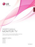
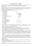
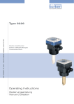
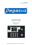
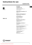
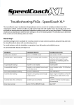
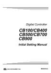
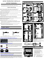
2. MOUNTING SIZE
44.0
Please Carefully read all the instructions in this manual.
Please place this manual in a convenient location for easy reference.
50
50
44.0
48mm*96mm
96mm*48mm
Unit:mm
48mm*48mm
Unit:mm
14.6
14.6
90.0
● Power Supply: 85~265VAC 50/60HZ, 24VDC or 24VAC available on request
● Input: : Thermocouple(K,E,J,N,Wu3_Re25,S,T,R,B,) Pt100( Up to 800 C)
Voltage and Current(0-5VDC,0-10VDC,0-50mV,4-20mV,0-20mA 2-10VDC, 1-5VDC, 4-20mA)
96
50
44.0
58.0
S P E C I F I C AT I O N
1
1
1 3 .6
80
1
● Display: Dual line 4 digits LED display
● Output: RELAY/SSR DRIVE/4-20mA/0-5VDC/0-10VDC/1-5VDC(specify when order)
90
67.5
UP
UP
74
14.6
● When anolog signal output, can using output buffer function when in some special
control position, which can make output more stable.
Check manual (6.1 level 2 bUFF parameter, and 6.3 level 2 bEr parameter)
90.0
1
1
13. 6
3.
96
67.5
80.0
● Alarm Standby function intergrated
● Power up overshoot suppression function intergreated.
● Analog output buffer function
80
13.6
1
48mm*96mm
AC85-265V
L
OUT
4
Power Up Overshoot Supression
DA - AL2
For
SSR mA,V
13
8
3
1
PV
L
2
3
NC
4
10
RS -485
TRS
9
A+
AL1
6
B-
9
7
10
8
11
9
NO
DA +
AL1
VDC/mA
11
OUT
NO
6
The LED display and LED indicators was built as one panel
,most of controller with their LED display and LED indicator
installed separately, the chance of the malfunction is high.
This controller with all the display and indicator units built
together on board, makes it easier to install and easy to test
with higher reliability.
15
DA -
16
RTD
12
For
SSR mA,V
B
B
13
NC
14
A
3.1 Wiring cautions
RTD
17
18
B
10
12
B
19
A
20
Alarm output rated:
Relay contact output:250V AC, 3A (Resistive load)
Control output rated:
Relay contact output: 250V AC,5A(Resistive load)
Voltage pulse output: 0/12 V DC or 0/24V DC (Load resistance
600 ohm or more)
Current output: 4 to 20mA DC (Load resistance 500 ohm or less)
Triac single phase zero crossing: 100A or less
13
TC
7
DA+
TC
ANL4/ANL3 IN
5
A+
VDC/mA
ANL4/ANL3 IN
NC
10
4
LED display and indicator built together on one PCB board
14
TRS
NO
The figure 1 shows significant overshoot after PV reaches to SV, this is harmful to some of
system, This controller offers a feature to suppress the overshoot
13
RS-485
8
AL2
DA -
8
B-
N
Figure 2
Figure 1
NO
NO
AC85-265V
PV
12
N
Voltage mA,V
OUT For SSR Current
5
Overshoot suppressed
11
AL2
NO
TC
A
96mm*96mm
L
2
9
B
14
DA + NO
5
SV
80
96mm*48mm
1
72mm*72mm
OverShoot
1
AC85-265V
7
B
TRS
NO
The overshoot is common when controller just power up, and the PV is getting closer to SV,
this controller offers a useful features for application where the overshoot should be tolerated
VDC,mA
IN
12 ANL4/ANL3
RTD
B-
3
6
N
11
A+
RS -485
AL1
NO
1. Unique Features
1
WIRING
48mm*48mm
2
14.6
96
74
● Modbus RTU RS-485 communication, SV/PV 4-20mA Re-transmission
● Output bar graphic indication( for analog output such as 4-20mA only)
● Controller can display based on Centigrade or Fahrenheit, switchable between each other.
SV
80
96mm*96mm
Unit:mm
72mm*72mm
Unit:mm
● Control method: PID, ON/OFF(P=0), Time proportional control(I=0, D=0)
● Measuring accuracy: 0.2%F.S
● Decimal points for all input signals: 0.1 resolution for thermocouple. 0.1 resolution for RTD.
0.001 for analog input
● ON/OFF Control: Set P=0.0,it will be changed as on/off control. Check
manual"6.1 parameter P " . Position difference is HYS. when heating :PV>SV, OUT
stop, when PV<SV-HYS, OUT start, fitting for OUT1. When Cooling:PV>SV+HYS,
output start, when PV<SV,output stop.
1
13 . 6
● Power consumption: 5VA maximum
104.0
INSTRUCTION MANUAL
104.0
DIGITAL TEMPERATURE CONTROLLER
14
Twist these leadwires
instrument power
IN
PV/SV Re-transmission(Optional function)
The PV or SV value can be re-transmitted as analog signal
0-5VDC,0-10VDC,4-20mA, and the re-transmission signal
can be feed to recorder ro digital display
OU T%
10
20
30
AL1
40
AL2
50
AL3
60
70
MAN COM
80
90
PRO
100
OUT 1 OUT 2
F to C
OU T%
10
20
AT
30
AL1
40
AL2
50
AL3
60
70
MAN COM
80
90
PRO
100
Instrument
power
terminals
4. PANEL DESCRIPTION
1
C to F
AT
OUT
Minimize
distance
Shorten distance between
pitches
C or F display selectable
OUT 1 OUT 2
Noise filter
This controller offers display based on Celcius and
Fahrenh-eit. can the display is switchable between C and F.
Decimal points for all input signals
The decimal points display is available for all input signals. For TC and RTD sensors, the
resolution is 0.1, for analog signal, the resolution is 0.001.
2
3
4
OUT1 OUT2
OUT%
10
20
AT
30
AL1
40
AL2
50
AL3
60
MAN
70
80
COM
PRO
90
100
5
Output restriction for analog output
Controller offers a function when output is analog such as 4-20mA, to maintain a stable
system, the output changing rate can be restrained in a certain range, for example, if the output changes from 4mA to 8mA in 1 seconds, then the changing rate is 4mA/S, the changing
rate can be restrained within 5%,means in the next seconds, the output only changes between
4mA*(1-5%) to 4mA*(1+5%). which is 3.8mA to 4.2mA.
1 Mea sured val ue (PV) di spl ay [RED]
2 Se t val ue (SV) di spl ay [GREEN ]
3 OUT1 lamp : Out pu t ind icat ion
OUT2 lamp : Rema rk lamp
AT lamp : Autot un ing ind icat ion
AL 1 lamp : Al ar m 1 ou tpu t ind icat ion
AL 2 lamp : Al ar m 2 ou tpu t ind icat ion
AL 3 lamp : Rema rk lamp
MAN lamp : Rema rk lamp
COM lamp : Comm un icat ion ind icat ion
PRG lamp : Rema rk lamp
4 LE D ba r: O ut pu t1 % val ue ind icat ion
5 SET key: Us ed for pa rame ter cal ling up an d set
val ue regi strat ion
6
7
8
6
7
8
: Sh ift key an d sett ing SV key
: Down key, de creas e numbe rs
: Up key ,inc reas e numbe rs
6.3 Level 2
5. SETTING
Press the
key while pressing the SET key for 3 s to PASS, set PASS=0101,
then press SET key to Level 2
5.1 Basic operation flow charts
PV
Power on
Power on
SV
Edition code
Input type display
The following parameter symbols are displayed one by one every time the SET key is pressed.
After the value be registered ,when no parameter setting is required, Press the SET key for 3 s
to return the instrument to the normal display.
1# Factory set value
Description
Range 1#
Symbol
Name
Main input
type select
PV
Edition code
SV
Setting
Input
J
E
K
N
Wu3_Re25
S
T
R
B
Range 1300°C 600°C 800°C 1300°C 2000°C 1600°C 400°C 1700°C 1800°C
PV/SV display mo de
(Normal display)
INPUT1
SV
Press
key
Setting
PV
SV setting mo de
Press the SE T key
for 3 seconds
SET
Input
Scale & type display
PV
Decimal point
Set range high
SV
SET
Press the
key and
SET simultaneously
for 3 seconds
High setting
PV/SV display mode
(Normal display)
SET
PASS
Display scale
PV follow-up
PV input filter
Lower limit for
PV display
Highe r limit for
PV displ ay
Display
Input
E
K
J
Wu3_Re25
N
S
T
R
B
Range 1300°C 600°C 800°C 1300°C 2000°C 1600°C 400°C 1700°C 1800°C
2-10VDC 0-10VDC
Pt100
1-5VDC 0-5VDC 0-50mV 0-20mV
4-20mA 0-20mA
800°C
PV
PV
PV
PV
SV
SV
SV
SV
In the normal display
modePress
key
to enter the SV setting
mode. The digit which
flashing is configurable.
Press the shift key
to
shift the digit which lig hts
brightly up to the hundreds
dights
Press the UP key
to set "2".
Pressing the UP key increase
numerals, and pressing the
DOWN key
decrease
numerals.
Alarm2
diffe rentia l gap
After finishing the setting, Press
the SET key, All of the set value
digits stop flash and as a result
the instrument return to
PV/SV display mode.
6. LEVEL
*In any ti me you can pre ss SET key fo r 3 seconds to save value and exit level to PV/S V mode.
6.1 Level 1
Press the SET key for 3 seconds to level 1:
The following parameter symbols are displayed one by one
every time the SET key is pressed.After the value be
registered ,when no parameter setting is required, Press the SET key for 3 s to return the
instrument to the normal display.
1# Factory set value
Description
Range
Symbol
1#
Name
Alarm 1
10
Alarm 2
-1999 to 9999
10
PV bias
-199to 199
Proportional 0.0 to 200.0
band
Control
0 to 999
Hysteresis
YES: Autotuning on,NO: Autotuning off
Set the alarm value for alarm 1 .
Alarm differential gap=AH1
Set the alarm value for alarm 2
Alarm differential gap=AH2
0.0
30.0
1.0
Sensor correction is made by adding bias
value to measured value(PV).
Proportional band in PID with unit ℃ for OUT1
P=0.0, ON/OFF control
Contro l out diffe rentia l gap=HYS
Only for ON/OFF actio n when P=0.0
240
Set the time of integral action to eliminate
the offset occurring in proportional control.
Der ivat ive time 0 to 3600 s
60
Proportioning
Cycle
20
Set the time of derivati ve acti on to improve
con trol stabi lity by prepa ring for output cha nges.
Proportioning cycle time for PID control
Integral time
Overshoot
protection
0 to 3600 s
0 to 999 s
Overshoot protection for first power on or SV modify later.
0.0 to 100.0 5.0
(Auto setting after autotuning)
Proportional reset for overshoot protection
(Auto setting after autotuning)
Output manipulated variable lowest limit
0.0
Proportional -199 to 200
reset
Output limit 0.0 to 100.0% 0.0
(Low)
Ou tput limi t 0.0 to 100.0% 100.0 Output manipulated variable highest limit
(High)
Output buffer 0.0 to 100% 100.0 Out put varianc e value per centage per second
buf fer limit Onl y for 4-20mA out put
Set data lock
6.2 PASS
0-2
LCK=0: Allow to modify any param eter and SV
LCK=1: Only all ow to modify SV and AT
LCK=2: Not all ow to modify any param eter and SV
0
Press the
key and the SET key simultaneously
for 3 seconds.
PV
Level 2
SV
Set PASS=0101
Press SET key
Select the type of alarm 1 ,See(**ALARM TYPE TABLE)
11
10
Buffer mode
0,1,2
for out1analog
output
Alarm1 diffe rentia l gap setti ng
Select the type of alarm 2 ,See(**ALARM TYPE TABLE)
PV
SV
SV
:Rever se act ion (Heati ng)
:Dir ect act ion (Cool ing)
1
0: No buff er for analog output 1
1: Always with buff er for analog output 1
2: With buff er when the output 1 increases only . (Soft -st art )
Output vari ance val ue percent age per second buff er limit
accordi ng BUFF in Level1
Communication device address setting.
9.6
BAUd=2.4K,4.8K,9.6K,19.2K
0
0-127
Alarm2 diffe rentia l gap setti ng
**ALARM TYPE TABLE (ALd_=00~16)
10: No alarm output
00: No alarm output
11: Deviation high alarm
01: Deviation high alarm with hold action
12: Deviation low alarm
02: Deviation low alarm with hold action
13: Deviation high/low alarm 03: Deviation high/low alarm with hold action
14: Deviation band alarm
04: Deviation band alarm with hold action
15: Process high alarm
05: Process high alarm with hold action
16: Process low alarm
06: Process low alarm with hold action
NOTE: With hol d act ion, When Hod act ion is ON, the alarm act ion is suppressed
at start-up unt il the measured val ue ent ers the non-al arm range.
7. AUTOTUNING
Auto-tuning shall be performed right after the power feed to controller when PV is far away from SV.
Aut otuning At
SET
PV
PV
SV
SV
Press SET key for
3 seconds to start
autotuning
Press key to set At=YE S
Press SET key for 3 s to Level1
1, When begin to autotuning, AT light flash, which means to begin to autotuning,if you want
to exit from autotuning, please enter into the AT menu, set AT=no
2,In the middle of the autotuning, it is ON/OFF control, according to the different systems,
temperature may be have a big variance and the autotuning time is of a long short.
3,After finishing autotuning, AT light stops flashing, controller will automatically save P、
I、d、rE、rSt parameters,then automatic return to the normal control state, controller
will continue to run with new P、I、d、rE、rSt parameters value.
8. INPUT RANGE TABLE
Input type
K
E
J
T
S
R
B
N
Wu3_Re25
PASS
PV
Hi gh es t va lue di sp lay when line ar an al og inp ut s
,Suc h as 4- 20 mA inp ut .
0.0 to 100.0 1.0
Band-ra te setti ng
-1999 to 9999
Lowes t value display when linea r ana log inpu ts
,Suc h as 4-20mA inpu t.
0
Control action HEAT or COOL HEAT
The setting procedures are the same as those of example (2) to (4) in the
above "Setting set value (SV)". Press the SET key after the
setting end shifts to the next parameter. When no parameter setting is
required, return the instrument to the PV/SV display mode.
NO
:Centigrade, :Fahrenheit
:without scale
PV variable-value control,
0-30: for general, 31-60: for enhanced
0.0 to 100.0 1.0
Device address
setting
NO or YES
SV lower limit value
Lower point of transmission
SV higher limit value
Higher point of transmission
-1999~9999 2000
5.3 Setting parameters other than set value (SV)
Autotuning
55
Alarm2 mode 00 to 16
(4) Set value entry
(3) Numeric value change
C
0 to 60
-199~9999
Alarm1
diffe rentia l gap
Example: Following is an example of set value(SV) to 200℃
(2)Shift of the digit brightly lit
C ,F or A
Pt100
800°C
0,1 for TC or RTD or analog type
2,3 Only for Linear analog type input
0
Alarm1 mode 00 to 16
5.2 Setting set value(SV)
(1)Set to the SV setting mode
0 to 3
-1999 to 99990
-1999 to 9999400
Low setting
Set range low
Leve l 1
2-10VDC 0-10VDC
1-5VDC 0-5VDC 0-50mV 0-20mV
4-20mA 0-20mA
Range
0
0
0
to
to
to
0
0
0
0
0
0
to
to
to
to
to
to
0
0
0
0
0
200
0
600
to
to
to
to
to
to
to
to
Code
0
400 C
600 0C
1300 0C
200 0C
0
400 C
600 0C
400 0C
600 0C
800 0C
0
200 C
300 0C
400 0C
1600 0C
1700 0C
1800 0C
0
1300 C
0
2000 C
K
K
K
A4
A6
B3
E
E
E
J
J
J
A2
A4
A6
A4
A6
A8
T
T
T
S
R
B
N
W
A2
A3
A4
B6
B7
B8
B3
B0
Input type
Pt100
to
0
to
0
to
0
-100 to
-200 to
-100.0 to
-50.0 to
Code
0
400 C
0
600 C
0
800 C
0
+200 C
0
+800 C
+200.00C
+200.00C
D
D
D
D
D
D
D
Input type
0 to 20mV
0 to 50mV
0 to 5VDC
0 to 10VDC
1 to 5VDC
2 to 10VDC
4 to 20mA
0 to 20mA
-1999
to 9999
-199.9 to 999.9
-19.99 to 99.99
-1.999 to 9.999
A4
A6
A8
C2
C8
F2
G2
Code
V
V
V
V
V
V
A
A
01
02
03
04
08
09
03
02
Note: Clients can set TC, RTD by keyboard ,please set the input type coincide with thesensor. Check details
of the manual"6.3"parameter INP1,If need analog signalinputs, please specified when order.
(Except 0-20mV or 0-50mV input)