1
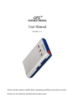
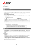
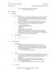
PART NO. INSTR –029 REL. 110513 REV. 001 © 2011 MTE Corporation Matrix PureSine – SineSync Monitoring Software User’s Manual IMPORTANT USER INFORMATION NOTICE ® The MTE Corporation Matrix PureSine Active Harmonic Filter is a powerful filtering solution for coordinated variable load power factor correction (PFC), phase imbalance correction, and harmonic mitigation. The suitability of this filter for a specific application must therefore be determined by the customer. In no event will MTE Corporation assume responsibility or liability for any direct or consequential damages resulting from the use or application of this filter. Nor will MTE Corporation assume patent liability with respect to the use of information, circuits or equipment described in this instruction manual. The purpose of this manual is to instruct the user on the requirements, installation, and operation of the Matrix PureSine monitoring software. In case any error message occurs, most of them can be identified and troubleshot through this manual. In case any error message occurs, which does appear in this manual, you have to contact with local authorized service agent for troubleshooting and repair. . 1 Part No. INSTR-029 REL. 110513 REV. 001 Matrix PureSine – SineSync Monitoring Software User’s Manual TABLE OF CONTENTS IMPORTANT USER INFORMATION.......................................................................................................... 1 TABLE OF CONTENTS ............................................................................................................................. 2 1. INTRODUCTION .................................................................................................................................... 3 1-1 SYSTEM REQUIREMENTS ....................................................................................................................... 3 2. INSTALLING SINESYNC........................................................................................................................ 4 3. USING SINESYNC SOFTWARE ............................................................................................................. 7 3-1 GETTING STARTED WITH SINESYNC ....................................................................................................... 7 3-2. STATUS & INFORMATION .................................................................................................................... 11 3-3. WAVEFORM ...................................................................................................................................... 14 3-4. SPECTRUM ........................................................................................................................................ 15 3-5. EVENT LOG ....................................................................................................................................... 17 3-6. COMPENSATION SELECTION ................................................................................................................ 18 3-7. PARALLEL INFORMATION ................................................................................................................... 23 3-8. DRY CONTACT SETTING ..................................................................................................................... 24 3-9. PARAMETER RECORD ......................................................................................................................... 26 3-10. DISCONNECTED ............................................................................................................................... 27 4. SINESYNC COMMUNICATION PORT SETTING ............................................................................... 28 4-1. TCP/IP SETTING................................................................................................................................ 28 4-2. USB SETTING ................................................................................................................................... 28 4-3. COM(RS-232) SETTING ..................................................................................................................... 29 4-4. RS-485/422 SETTING ......................................................................................................................... 29 2 Part No. INSTR-029 REL. 110513 REV. 001 Matrix PureSine – SineSync Monitoring Software User’s Manual 1. Introduction SineSync is the monitoring software for the Matrix PureSine. Users can use this software to monitor the operation status of the PureSine and download the waveform, spectrum, and event log data from the PureSine. This manual explains how to install and operate SineSync. 1-1 System Requirements Basic requirements: Pentium-Ⅲ 800M Hz, 256MB, HD500MB Microsoft Windows 2000 Display 1024x768 Recommend requirement Pentium-4 1.8G Hz, 512MB, HD2GB Microsoft Windows XP Display 1024x768 3 Part No. INSTR-029 REL. 110513 REV. 001 Matrix PureSine – SineSync Monitoring Software User’s Manual 2. Installing SineSync The installation steps are as follows, Step 1: Double click Setup.exe to start the installation; refer to figure 2-1. Figure 2-1 Step 2: If you agree with the Software License Agreement, please click “ACCEPT” to continue the installation. If not, please click “DO NOT ACCEPT” to stop the installation; refer to figure 2-2. Figure 2-2 4 Part No. INSTR-029 REL. 110513 REV. 001 Matrix PureSine – SineSync Monitoring Software User’s Manual Step 3: Click the “OK” button to continue the installation; refer to figure 2-3. Figure 2-3 Step 4: Change the directory if desired to a specified destination directory and then click install this program; refer to figure 2-4. button to Figure 2-4 5 Part No. INSTR-029 REL. 110513 REV. 001 Matrix PureSine – SineSync Monitoring Software User’s Manual Step 5: Enter the program group name and click the “Continue” button to continue installing the program; refer to figure 2-5. Figure 2-5 Step 6: SineSync has been successfully installed. Click the “OK” button to exit the installation; refer to figure 2-6. Figure 2-6 Step 7: Now you can start the SineSync Monitoring Software. 6 Part No. INSTR-029 REL. 110513 REV. 001 Matrix PureSine – SineSync Monitoring Software User’s Manual 3. Using SineSync Software 3-1 Getting Started with SineSync Step 1: Start SineSync by clicking on the “SineSync” icon; refer to figure 3-1. Figure 3-1 Step 2: Please key in the Serial number and Password, and then click the Register button to register this software; refer to figure 3-2. If the Serial number or Password is incorrect, SineSync cannot be started. Figure 3-2 7 Part No. INSTR-029 REL. 110513 REV. 001 Matrix PureSine – SineSync Monitoring Software User’s Manual Step 3: Figure 3-3 shows the setting window of the SineSync software Figure 3-3 a. Enter system:Enters the SineSync main program window. b. Function: Add new APF:Add a PureSine Control Module to this monitoring system. The maximum number of units the monitoring system can handle is 255. Delete APF:Delete a PureSine Control Module from the monitoring system. Record interval of parameter:To set the record period for the power parameters, set the date you want to start and end the record time. The record interval time can be set from 1 to 60 minutes; refer to figure 3-4. Note: The hard disk space is less than 100MB after recording 1 record per minute for one PureSine for one year. Figure 3-4 c. About:Displays the SineSync software information. d. ID:This is the Identification number of the PureSine. Each PureSine has an ID number that is stored in the EEPROM of the PureSine controller. This identification number has to be the same as the ID number that is stored in the EEPROM of the PureSine controller. If the numbers are different, the computer cannot communicate with the PureSine. Users can use the “SineSync Setting Tool” to read and set the ID numbers. For further details, please refer to “Matrix PureSine User's Manual”. 8 Part No. INSTR-029 REL. 110513 REV. 001 Matrix PureSine – SineSync Monitoring Software User’s Manual e. Name:User defined identification name for the PureSine. f. Baud Rate:Baud Rate has to be set to the same as the communication card. Users can use “SineSync Setting Tool” to set the Baud Rate of the communication card. For further details, please refer to “Matrix PureSine User's Manual”. g. Connected type:COM, USB and TCP/IP are the three types of communication ports that can be selected. The correct type of communication port that is used to connect to the PureSine needs to be selected. For further details, please refer to Chapter 4 of this manual. h. Record:When this option is selected; the PureSine power parameters are recorded. Step 4: When all of the settings are completed, please select “Enter system”, which will open the SineSync main window; refer to figure 3-5. The functions of main window are described below. Figure 3-5 a. Communication Status: Connected. Disconnected. b. Parameter Record Status: When the power parameters record function is enabled, the icon will be showed. On the other hand, icon will be hidden. When the parameter data is recording, the icon will be blinking. c. Name: The user defined identification name of the PureSine. Double click this name to see more detailed information. d. Filter Name: The identification name of the PureSine from the Control Unit. Double click this name to see more detail information. e. Filtering: When the PureSine is filtering, the indicator is green indicator is white . When the PureSine is not filtering, this . 9 Part No. INSTR-029 REL. 110513 REV. 001 Matrix PureSine – SineSync Monitoring Software User’s Manual f. Full Correcting: When the PureSine operates under full load condition, the indicator is yellow hand, this indicator is white g. . On the other . Error : During possible external and internal fault conditions the indicator turns red should be stopped. On the other hand, this indicator is white and the PureSine . h. Phase/Wire: Displays the utility system, 3 phase 3 wire. i. Freq.: Displays the utility frequency, 50Hz or 60Hz. j. Panel: Displays the control panel type, LCD. k. Event: Displays the newest event or status of the PureSine. To change any of the original settings, select FunctionGo to Setting Page to come back setting window. Table 3-1 shows the lists of functions the SineSync is able to display with the LCD panel. Table 3-1 Function list of the SineSync Panel LCD Panel Function Status ● Identification ● Parameters ● Waveform ● Spectrum ● Event Log ● Compensation Selection ● Dry Contract ● Parameter Record ● ●:Support this function Χ:Without this function 10 Part No. INSTR-029 REL. 110513 REV. 001 Matrix PureSine – SineSync Monitoring Software User’s Manual 3-2. Status & Information Figure 3-6 shows the Status & Information window. All of the functions are described below. Figure 3-6 a. Functions: Users can use this menu to switch between function windows. 1) Status & Information 2) Waveform 3) Spectrum 4) Event log 5) Compensation Selection 6) Parallel Information 7) Dry Contact Setting 8) Parameter Record b. Status: 1) Filtering: When the PureSine is filtering, this indicator is green. 2) Full Correcting: When the PureSine operates under full load condition, this indicator is yellow. 3) Error: During possible external and internal fault conditions the indicator is red, the PureSine should be stopped. 11 Part No. INSTR-029 REL. 110513 REV. 001 Matrix PureSine – SineSync Monitoring Software User’s Manual 4) Internal CAN BUS: When the communication between the PureSine control board and the LCD panel is normal, the indicator is green. If the communication is abnormal, the indicator is red. 5) CPU1 Controller Ver.: Displays the CPU1 controller version. 6) CPU2 Controller Ver.: Displays the CPU2 controller version. 7) LCD Panel Program Ver.: Displays the LCD Panel controller version. c. Control Button: 1) ON/OFF: Only the Authorized Administrator can click this button to control the PureSine. 2) RESET : Click this button to clear the error status. d. Identification:Displays the information of the PureSine. 1) Name:The identification name of the PureSine. 2) Filter Name:The identification name of PureSine from the Control Unit. 3) ID:The Identification number of the PureSine. 4) Model Number:Model number of the PureSine. 5) Serial Number:Serial number of the PureSine. 6) Rated Voltage:Rated voltage of the PureSine. 7) Module Current:Rated current of the Power Module. 8) Rated Current:Rated current of the PureSine. 9) Phase/Wire:Displays the utility system, 3P3W. 10) Frequency:Displays the utility frequency, 50Hz or 60Hz. 11) Number of Parallel Unit:Displays the number of parallel Control Modules. 12) Parallel Number:Displays the parallel number of the Control Module. e. Parameters:Displays the power parameter information. 1) Frequency:Utility frequency. 2) 3 phase voltage: 2-1) Vab, Vbc, Vca:RMS Voltage. 2-2) THDv:Total Harmonic Voltage Distortion. 3) Load Side: 3-1) KVA:Complex Power of the Load side. 12 Part No. INSTR-029 REL. 110513 REV. 001 Matrix PureSine – SineSync Monitoring Software User’s Manual 3-2) PF:Power Factor of the Load side. 3-3) ILa, ILb, ILc, In:Load side RMS Current. 3-4) THDi:Total Harmonic Current Distortion of the Load Side. 4) Source Side: 4-1) KVA:Complex Power of the Source side. 4-2) PF:Power Factor of the Source side. 4-3) ISa, ISb, ISc, In:Source side RMS Current. 4-4) THDi:Total Harmonic Current Distortion of the Source Side. 5) Filter Side: 5-1) KVA:Complex Power of the Filter side. 5-2) IFa, IFb, IFc, In:Filter side RMS Current. f. Load Rate:The percentage of the PureSine output current. g. Export: Export the parameter data to a Comma Separated Value (CSV) file format. 13 Part No. INSTR-029 REL. 110513 REV. 001 Matrix PureSine – SineSync Monitoring Software User’s Manual 3-3. Waveform Figure 3-7 shows the Waveform window. This window can display waveforms for the voltages and currents of the Source, Load and Filter side. Figure 3-7 a. Update:Click the Update button to download the waveform from the PureSine. b. Export:Click the Export button to store the waveform data to a Comma Separated Value file. c. Color:Click the Color button to change the waveform color. d. Scale:Click the up/down button to change the current scale. 1) IL/IS:Source side current and Load side current. 2) IF:Filter side current. e. Menu for waveform window 1. 1) Vab, Vbc, Vca:3 phase line voltage waveform. 2) ILa, ILb, ILc, ILn:3 phase current waveform of Load side. 3) ISa, ISb, ISc, ISn:3 phase current waveform of Source side. 4) IFa, IFb, IFc, IFn:3 phase current waveform of Filter side. f. Menu for waveform window 2. g. Display of waveform window 1. h. Display of waveform window 2. 14 Part No. INSTR-029 REL. 110513 REV. 001 Matrix PureSine – SineSync Monitoring Software User’s Manual 3-4. Spectrum Figure 3-8 and figure 3-9 are the Spectrum windows. Figure 3-8 shows Spectrum in as a graph and figure 3-9 shows Spectrum in data table. User can use this function to view the spectrum of the voltages and currents. a. Update:Click the Update button to download the spectrum data from the PureSine. b. Export:Click the Export button to store the waveform data in a Comma Separated Value file. c. Color:Click the Color button to change the color of spectrum bar. d. Spectrum:Click the Spectrum button and to see the spectrum in a graph. e. Table:Click the Table button and to see the spectrum data in table. f. The Spectrum menu to choose the voltages and currents. 1) Vab, Vbc, Vca:3 phase line voltage. 2) ILa, ILb, ILc:3 phase current of the Load side. 3) ISa, ISb, ISc:3 phase current of the Source side. Figure 3-8 15 Part No. INSTR-029 REL. 110513 REV. 001 Matrix PureSine – SineSync Monitoring Software User’s Manual Figure 3-9 16 Part No. INSTR-029 REL. 110513 REV. 001 Matrix PureSine – SineSync Monitoring Software User’s Manual 3-5. Event log Figure 3-10 shows the Event log window. Users can download the event logs from the PureSine. Figure 3-10 a. Update:Click the Update button to download the event log data from the PureSine. b. Export:Click the Export button to store the event log data in a Comma Separated Value file. c. Count:Choose the number of event logs to download. 17 Part No. INSTR-029 REL. 110513 REV. 001 Matrix PureSine – SineSync Monitoring Software User’s Manual 3-6. Compensation Selection Figure 3-11 and figure 3-12 show the Compensation Selection window. NOTE This window only provides the user the ability to view the compensation settings of the PureSine. The user cannot change any of these settings. If the User wants to change the setting, please contact a local authorized service agent. 3-6-1. Setting Function A. Compensation Setting Table 3-2 Compensation Setting Descriptions Item Harmonic Compensation Power Factor Correction Compensation Priority Reactive Power Target DPF (cos ¢) Function Description Enable or disable the Harmonic Compensation. Enable or disable the Power Factor Correction. To set the priority of the compensation, either Harmonic Compensation or Power Factor Correction. To set the reactive power compensation mode. Dynamic when Harmonic Compensation is enabled. Fixed when Power Factor Correction is enabling. To set the Target DPF cos¢1 when Harmonic Compensation is enabled. Option or Input Range ENABLE or DISABLE ENABLE or DISABLE Harmonic or PFC Default ENABLE ENABLE Harmonic Dynamic or Fixed Dynamic : leading : lagging 0.95 0.7~1.0 Fixed KVAR To set the Fixed KVAR when Power Factor Correction is enabled. Balance Utility The Balance Utility will compensate for any unbalance from the utility current. This function is not available at this time. : leading : lagging Please refer to table 3-3 for input range. ENABLE or DISABLE 0 DISABLE 0~6 Application Mode PureSine has several control parameters for different type of loads to obtain the best performance. 18 Please refer to table 3-4. Part No. INSTR-029 REL. 110513 REV. 001 5 Matrix PureSine – SineSync Monitoring Software User’s Manual Table 3-3 Fixed KVAR Input Range Application Mode 0 1 2 3 4 5 6 Table 3-4 Application Mode Description Description For single phase rectifier. For 3P3W 6pulse rectifier. For 3P3W 6pulse and single phase rectifiers. For 3P3W 6pulse rectifier with even order harmonic. For single phase rectifier with even order harmonic. For all type loads. For all type loads. Figure 3-11 19 Part No. INSTR-029 REL. 110513 REV. 001 Matrix PureSine – SineSync Monitoring Software User’s Manual B. Compensation Logic Control Table 3-5 Compensation Logic Control Description Item Function Description When this function is enabled, the filter can start-up or shutdown automatically, according to the load current level. Smart Save Energy Smart Save Energy When the load current is less than Min. OFF Current Level, or the load current becomes greater than Max. ON Current Level, the filter will shut down automatically. ON Delay Time The delay time for automatic start-up. OFF Delay Time The delay time for automatic shutdown. Option or Input Range Default ENABLE or DISABLE DISABLE 0~3600 Seconds 0~3600 Seconds 10 10 The current level for automatic start-up. Max. ON Current Level For example, if the Max. ON Current Level is 1.5 for a 60A PureSine, it means the load current has to greater than 90A. 0.1~10.0 1.0 0.1~10.0 0.5 ENABLE or DISABLE ENABLE 0~3600 Seconds 10 This current level has to greater than Min. OFF Current Level. The current level for automatic shutdown. Min. OFF Current Level Auto ReStart Auto Re-Start Delay Time For example, if the Min. OFF Current Level is 0.5 for a 60A PureSine, it means the load current has to greater than 30A. This current level has to less than Max. ON Current Level. When this function is enabled, the PureSine is allowed to automatically restart when some abnormal conditions return to normal. The delay time for automatic re-start. 20 Part No. INSTR-029 REL. 110513 REV. 001 Matrix PureSine – SineSync Monitoring Software User’s Manual C. System Setting Table 3-6 System Setting Description Item Function Description Option or Input Range Default Phase/Wire Select the 3P3W power system for the PureSine connection. A neutral line doesn’t need to be connected. 3P3W 3P3W Number of External CT Select 2 or 3 external CTs that will be installed at Source or Load side. 3 CTs is preferred. 2 CTs 3 CTs 3 CTs Primary Ampere of CT Set the primary current rating of the External CT. 100~10000 1000 1A 5A Auto Detection Load Source Source ENABLE DISABLE ENABLE Set the secondary current rating of External CT. Secondary Ampere of CT CT Position The Control Module can accept a 1A or 5A rating. If 5A CT will be used, an optional auxiliary CT card is needed. Select the location where the External CTs are installed. When this function is enabled, the PureSine will diagnose the polarity of External CT. CT Direction Detection If the polarity is incorrect, the PureSine will display an alarm and will not start. Phase A CT If the polarity of the External CT of Phase A is incorrect, this function can change the CT polarity without reconnecting the CT wires. Normal Reverse Normal Phase B CT If the polarity of the External CT of Phase B is incorrect, this function can change the CT polarity without reconnecting the CT wires. Normal Reverse Normal Phase C CT If the polarity of the External CT of Phase C is incorrect, this function can change the CT polarity without reconnecting the CT wires. Normal Reverse Normal Parallel CT Ratio When the Control Modules are connected in parallel each phase has to install 1 CT. 500/1 1000/1 2000/1 500/1 190~6600V 480 Different voltage levels can be applied to the PureSine with an external transformer that is installed at the input side of the filter. Primary Voltage Level When an external transformer is used, the voltage level should be set to primary voltage of the transformer. 21 Part No. INSTR-029 REL. 110513 REV. 001 Matrix PureSine – SineSync Monitoring Software User’s Manual 3-6-2. Harmonic Function a. Order: Shows the harmonic order that the PureSine will compensate. The maximum number of harmonic orders that can be selected at once is 12. b. Active: The function shows the harmonic orders which are compensated by the PureSine. The filter will disable the harmonic order if resonance occurs between the PureSine and load. c. Reduction (%): The function sets the harmonic current reduction ratio. th For example, when the load 5 harmonic current is 10A and the reduction is set 80%, the th PureSine only compensate 8A of the 5 harmonic current. d. High Order Compensation: The function enables the PureSine to compensate from 32 nd st to 51 harmonic orders. Figure 3-12 22 Part No. INSTR-029 REL. 110513 REV. 001 Matrix PureSine – SineSync Monitoring Software User’s Manual 3-7. Parallel Information Figure 3-13 shows the Parallel Information window on a system level. It will show the status of Control Modules and the rated current of the total Power Modules which are connected to a Control Module. As a reference, one Control Module can be connected with a total 4 numbers Power Module totaling a maximum compensating current of 120 Amps. 8 of such units can be paralleled to offer a maximum compensating current of 960 Amps. Figure 3-13 When user connects to the Centralized Control Unit, it will show the window seen in Figure 3-14. Figure 3-14 Indicator: This indicator will be green when the PureSine turns on, otherwise it will be white. When one of the units experiences an abnormal condition, this indicator will become red. NOTE ON/OFF Button to turn on and off each PureSine is only available for Authorized Administrators. 23 Part No. INSTR-029 REL. 110513 REV. 001 Matrix PureSine – SineSync Monitoring Software User’s Manual 3-8. Dry Contact Setting Figure 3-15 shows the Dry Contact Setting window. Users can define the actions of each dry contact with this window. Click the “Edit” button to enter the window to modify the dry contact settings (figure 316). There are 38 action events that can be set (refer to table 3-7) and the action mode can be set to either NO (Normal Open) or NC (Normal Close). After finish defining the settings, click the “Update” button to store the new settings. The default settings for the dry contacts are listed in Table 3-8. The Remote Control sets the function of input dry contact. For a detailed description of the input dry contact refer to Section 2-1-2(D) of the “Matrix PureSine User's Manual”. Figure 3-15 Figure 3-16 24 Part No. INSTR-029 REL. 110513 REV. 001 Matrix PureSine – SineSync Monitoring Software User’s Manual Item 1 3 5 7 9 11 13 15 17 19 21 23 25 27 29 31 33 35 37 Table 3-7 Event list Item POWER ON 2 Full correcting 4 MCCB Tripped 6 Input Power Abnormal 8 High Frequency Resonance 10 Over Current 12 Fan Fault 14 DC Bus Error 16 DC Bus Over Voltage 18 External CTB Reversed 20 Parallel CTA Reversed 22 Parallel CTC Reversed 24 System Under Voltage 26 Frequency Error 28 Control Board Error 30 Control Panel EEPROM Error 32 Current Cable Disconnected 34 Parallel Disconnected 36 Parallel Setting Error 38 Event Event Filtering ERROR Fuse Blown IGBT Fault Over Peak Current Over Temperature(Power) Temp. Sensor Disconnected DC Bus Under Voltage External CTA Reversed External CTC Reversed Parallel CTB Reversed System Voltage Abnormal System Over Voltage Phase Rotation Error Control Board EEPROM Error Power Supply Error CAN Bus Disconnected Parallel ID Duplicated Over Temperature(Control) Table 3-8 The Default Definition of the Output Dry Contacts Dry Contact Event Active Dry Contact 1 POWER ON NO (Normal Open) Dry Contact 2 Filtering NO (Normal Open) Dry Contact 3 Full correcting NO (Normal Open) Dry Contact 4 ERROR NO (Normal Open) Dry Contact 5 DC Bus Error NO (Normal Open) 25 Part No. INSTR-029 REL. 110513 REV. 001 Matrix PureSine – SineSync Monitoring Software User’s Manual 3-9. Parameter Record Figure 3-17 shows the Parameter Record window. This window displays the power parameter records. Figure 3-17 a. Viewing Period:Sets the start and end viewing times. b. Option:Selects the power parameters the user wants to view. c. View:Click the “View” button to load the power parameters data. d. Export:Click the “Export” button to store the power parameters data in a Comma Separated Value (CSV) file. e. Delete Records:Click the “Delete Records” button to set the start and end time of the records desired to be deleted. See Figure 3-19. Click the “Delete” button to delete the power parameters data from the database. Figure 3-18 26 Part No. INSTR-029 REL. 110513 REV. 001 Matrix PureSine – SineSync Monitoring Software User’s Manual 3-10. Disconnected When the communication between the computer and the PureSine is disconnected, the SineSync main window will display the disconnected symbol and a de-link message. Please refer to figure 3-19 and figure 3-20. When the communication is disconnected, please check if the communication cable between the computer and PureSine is properly connected and that the communication card is operating properly. If the problem persists, please contact a local authorized service agent. Figure 3-19 Figure 3-20 27 Part No. INSTR-029 REL. 110513 REV. 001 Matrix PureSine – SineSync Monitoring Software User’s Manual 4. SineSync Communication Port Setting 4-1. TCP/IP Setting When the communication port type is TCP/IP, the user has to set the ID, Baud Rate, and IP Address. The ID number has to the same as the PureSine, and the Baud Rate and IP Address have to the same as the communication card of the PureSine. Note: The TCP/IP communication port communicates with the external network by port 1000. If you have to communicate with an external network, please ask your system administrator to release port 1000. Figure 4-1 4-2. USB Setting When the communication port type is USB, the user has to set the ID and the Baud Rate. The ID number has to the same as the PureSine, and the Baud Rate has to the same as the communication card of the PureSine. Figure 4-2 28 Part No. INSTR-029 REL. 110513 REV. 001 Matrix PureSine – SineSync Monitoring Software User’s Manual 4-3. COM(RS-232) Setting When the communication port type is COMx, the user has to set the ID and the Baud Rate. The ID number has to the same as the PureSine, and the Baud Rate has to the same as the communication card of the PureSine. If the user is using a USB to RS232 converter, please ensure that the COM port setting is correct. Figure 4-3 4-4. RS-485/422 Setting When the user uses the RS-485/422 communication card, the communication port type is COMx. The user has to set the ID and the Baud Rate. The ID number has to the same as the PureSine, and the Baud Rate has to the same as the communication card of the PureSine. 29 Part No. INSTR-029 REL. 110513 REV. 001