1
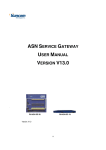
6 Troubleshooting and Maintenance
6-2
Troubleshooting with the User
Defined CAN Unit Indicators
The User Defined CAN Unit has several indicators on the front of the Unit. Two 7-segment displays with
dots and two error LED indicators.
2. Two-digit, 7-segment display
RUN
1.
1. Status indicators
ERR
3. Dot indicators
6-2-1
Run LED Indicator
Indicator Status
Network/Unit Status
Color
Green
Comments
Status
OFF
No power or in ST1 or ST2 state
Make sure that the unit is wired and
mounted correctly, switch the power on or
wait for until unit to be initialized.
ON
State is ST3, ST4 or ST5
Configure the unit with message command
2902 or enable communication by turning
ON *_EnblCANComm.
Enabled communication is confirmed when
*_EnblComm is ON or the unit is waiting for
CAN messages.
Red
OFF
No power or in ST1 or ST2
Make sure that the unit is wired and
mounted correctly, switch the power on or
wait for the until unit to be initialized.
Flashing
ST1 (PC21 startup error) or ST2 (hardware
error)
Verify proper unit number setting.
Fatal error in unit
Restart Unit.
ON
If problem persists, contact an Omron representative.
If problem persists, contact and Omron
representative.
6-4
CJ-series User Defined CAN Unit Operation Manual for NJ-series CPU Unit (W517)