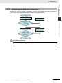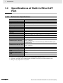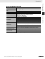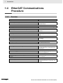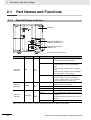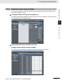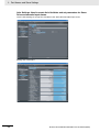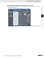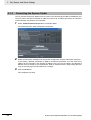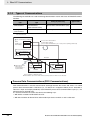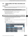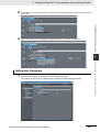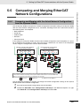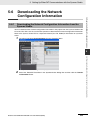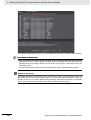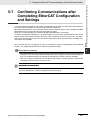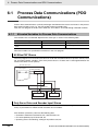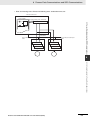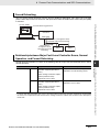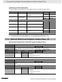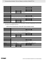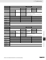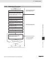
1
Machine Automation Controller NJ-series CPU Unit Built-in EtherCAT Port User’s Manual NJ501-1300 NJ501-1400 NJ501-1500 CPU Unit W505-E1-01 OMRON, 2011 All rights reserved. No part of this publication may be reproduced, stored in a retrieval system, or transmitted, in any form, or by any means, mechanical, electronic, photocopying, recording, or otherwise, without the prior written permission of OMRON. No patent liability is assumed with respect to the use of the information contained herein. Moreover, because OMRON is constantly striving to improve its high-quality products, the information contained in this manual is subject to change without notice. Every precaution has been taken in the preparation of this manual. Nevertheless, OMRON assumes no responsibility for errors or omissions. Neither is any liability assumed for damages resulting from the use of the information contained in this publication. Introduction Introduction Thank you for purchasing an NJ-series CPU Unit. This manual contains information that is necessary to use the NJ-series CPU Unit. Please read this manual and make sure you understand the functionality and performance of the NJ-series CPU Unit before you attempt to use it in a control system. Keep this manual in a safe place where it will be available for reference during operation. Intended Audience This manual is intended for the following personnel, who must also have knowledge of electrical systems (an electrical engineer or the equivalent). • Personnel in charge of introducing FA systems. • Personnel in charge of designing FA systems. • Personnel in charge of installing and maintaining FA systems. • Personnel in charge of managing FA systems and facilities. For programming, this manual is intended for personnel who understand the programming language specifications in international standard IEC 61131-3 or Japanese standard JIS B3503. Applicable Products This manual covers the following products. • NJ-series CPU Units • NJ501-1300 • NJ501-1400 • NJ501-1500 NJ-series CPU Unit Built-in EtherCAT Port User’s Manual (W505) 1 Relevant Manuals Relevant Manuals There are three manuals that provide basic information on the NJ-series CPU Units: the NJ-series CPU Unit Hardware User’s Manual, the NJ-series CPU Unit Software User’s Manual (this manual), and the NJ-series Instructions Reference Manual. Most operations are performed from the Sysmac Studio Automation Software. Refer to the Sysmac Studio Version 1 Operation Manual (Cat. No. W504) for information on the Sysmac Studio. Other manuals are necessary for specific system configurations and applications. Read all of the manuals that are relevant to your system configuration and application to make the most of the NJ-series CPU Unit. NJ-series User’s Manuals CJ-series Special Unit Operation Manuals for NJ-series CPU Unit NJ-series Troubleshooting Manual NJ-series CPU Unit Built-in EtherNet/IP Port User´s Manual NJ-series Motion Control Instructions Reference Manual NJ-series CPU Unit Built-in EtherCAT Port User´s Manual NJ-series CPU Unit Motion Control User´s Manual NJ-series Instructions Reference Manual NJ-series CPU Unit Software User´s Manual NJ-series CPU Unit Hardware User´s Manual Basic information Introduction to NJ-series Controllers Setting devices and hardware Using motion control Using EtherCAT Using EtherNet/IP Using CJ-series Units Software settings Using motion control Using EtherCAT Using EtherNet/IP Programming Using motion control Using EtherCAT Using CJ-series Units Programming error processing Testing operation and debugging Using motion control Using EtherCAT Using EtherNet/IP Troubleshooting and managing errors in an NJ-series Controller Use the relevant manuals for references according to any error that occurs. Maintenance Using EtherCAT Using EtherNet/IP Using CJ-series Units 2 NJ-series CPU Unit Built-in EtherCAT Port User’s Manual (W505) Manual Configuration Manual Configuration NJ-series CPU Unit Hardware User’s Manual (Cat. No. W500) Section Description Section 1 Introduction This section provides an introduction to the NJ-series Controllers and their features, and gives the NJ-series Controller specifications. Section 2 System Configuration This section describes the system configuration used for NJ-series Controllers. Section 3 Configuration Units This section describes the parts and functions of the configuration devices in the NJseries Controller configuration, including the CPU Unit and Configuration Units. Section 4 Installation and Wiring This section describes where and how to install the CPU Unit and Configuration Units and how to wire them. Section 5 Troubleshooting This section describes the event codes, error confirmation methods, and corrections for errors that can occur. Section 6 Inspection and Maintenance This section describes the contents of periodic inspections, the service life of the Battery and Power Supply Units, and replacement methods for the Battery and Power Supply Units. Appendices The appendices provide the specifications of the Basic I/O Units, Unit dimensions, load short-circuit protection detection, line disconnection detection, and measures for EMC Directives. NJ-series CPU Unit Software User’s Manual (Cat. No. W501) Section Description Section 1 Introduction This section provides an introduction to the NJ-series Controllers and their features, and gives the NJ-series Controller specifications. Section 2 CPU Unit Operation This section describes the variables and control systems of the CPU Unit and CPU Unit status. Section 3 I/O Ports, Slave Configuration, and Unit Configuration This section describes how to use I/O ports, how to create the slave configuration and unit configuration and how to assign functions. Section 4 Controller Setup This section describes the initial settings of the function modules. Section 5 Designing Tasks This section describes the task system and types of tasks. Section 6 Programming This section describes programming, including the programming languages and the variables and instructions that are used in programming. Section 7 Simulation, Transferring Projects to the Physical CPU Unit, and Operation This section describes simulation of Controller operation and how to use the results of simulation. Section 8 CPU Unit Status This section describes CPU Unit status. Section 9 CPU Unit Functions This section describes the functionality provided by the CPU Unit. Section 10 Communications Setup This section describes how to go online with the CPU Unit and how to connect to other devices. Section 11 Example of Actual Application Procedures This section describes the procedures that are used to actually operate an NJ-series Controller. Section 12 Troubleshooting This section describes the event codes, error confirmation methods, and corrections for errors that can occur. Appendices The appendices provide the CPU Unit specifications, task execution times, systemdefined variable lists, data attribute lists, CJ-series Unit memory information, CJseries Unit memory allocation methods, and data type conversion information. NJ-series CPU Unit Built-in EtherCAT Port User’s Manual (W505) 3 Manual Configuration NJ-series CPU Unit Built-in EtherCAT Port User’s Manual (Cat. No. W505) (This Manual) Section 4 Description Section 1 Introduction This section provides an overview of EtherCAT communications, describes the system configuration and specifications, and provides operating procedures. Section 2 Part Names and Slave Settings This section provides the part names and describes the slave settings and Sysmac device functions. Section 3 EtherCAT Communications This section describes the different types of EtherCAT communications, EtherCAT settings, and state transitions. Section 4 EtherCAT Network Wiring This section describes how to connect and wire an EtherCAT network. Section 5 Setting Up EtherCAT Communications with the Sysmac Studio This section describes how to set the network configuration information and how to check EtherCAT communications from the Sysmac Studio. Section 6 Process Data Communications and SDO Communications This section describes the timing of communications, response times, and special instructions for process data communications and SDO communications. It also provides sample programming. Section 7 System-defined Variables That Are Related to the Built-in EtherCAT Port This section describes the system-defined variables that are related to the built-in EtherCAT port. Section 8 Example of Operations for EtherCAT Communications This section provides a series of example operations for when an NJ-series CPU Unit is connected to slaves. Section 9 Troubleshooting This section describes the event codes, error confirmation methods, and corrections for errors that can occur for EtherCAT communications. It also describes how to replace slaves. Appendices The appendices describe the relation of EtherCAT communications to overall CPU Unit status, packet monitoring functions, and multi-vendor application. NJ-series CPU Unit Built-in EtherCAT Port User’s Manual (W505) Manual Configuration Sysmac Studio Version 1 Operation Manual (Cat. No. W504) Section Description Section 1 Introduction This section provides an overview and lists the specifications of the Sysmac Studio and describes its features and components. Section 2 Installation and Uninstallation This section describes how to install and uninstall the Sysmac Studio. Section 3 System Design This section describes the basic concepts for designing an NJ-series System with the Sysmac Studio and the basic operating procedures. Section 4 Programming This section describes how to create programs with the Sysmac Studio. Section 5 Online Connections to a Controller This section describes how to go online with a Controller. Section 6 Debugging This section describes how to debug the programs online on the Controller or debug it offline with the Simulator. Section 7 Other Functions This section describes Sysmac Studio functions other than system design functions. Section 8 Reusing Programming This section describes how to reuse the programs that you create with the Sysmac Studio. Section 9 Support Software Provided with the Sysmac Studio This section describes the Support Software that is provided with the Sysmac Studio. Section 10 Troubleshooting This section describes the error messages that are displayed when you check a program on the Sysmac Studio and how to correct those errors. Appendices The appendices describe the following: Driver Installation for Direct USB Cable Connection Specifying One of Multiple Ethernet Interface Cards Online Help Simulation Instructions NJ-series CPU Unit Built-in EtherCAT Port User’s Manual (W505) 5 Manual Structure Manual Structure Page Structure The following page structure is used in this manual. Mounting Units Level 1 heading Level 2 heading Level 3 heading Connecting Controller Components Gives the current headings. 4 Installation and Wiring Level 2 heading 4-3 Level 3 heading 4-3-1 The Units that make up an NJ-series Controller can be connected simply by pressing the Units together and locking the sliders by moving them toward the back of the Units. The End Cover is connected in the same way to the Unit on the far right side of the Controller. A step in a procedure 1 Join the Units so that the connectors fit exactly. Hook Indicates a procedure. Hook holes Connector 4-3 Mounting Units 4 The yellow sliders at the top and bottom of each Unit lock the Units together. Move the sliders toward the back of the Units as shown below until they click into place. Move the sliders toward the back until they lock into place. Lock Release Slider Gives the number of the main section. Precautions for Correct Use Special information The sliders on the tops and bottoms of the Power Supply Unit, CPU Unit, I/O Units, Special I/O Units, and CPU Bus Units must be completely locked (until they click into place) after connecting the adjacent Unit connectors. Icons indicate precautions, additional information, or reference information. Manual name 4-3-1 Connecting Controller Components 2 Page tab 4-9 NJ-series CPU Unit Hardware User’s Manual (W500) This illustration is provided only as a sample. It may not literally appear in this manual. Special Information Special information in this manual is classified as follows: Precautions for Safe Use Precautions on what to do and what not to do to ensure safe usage of the product. Precautions for Correct Use Precautions on what to do and what not to do to ensure proper operation and performance. Additional Information Additional information to read as required. This information is provided to increase understanding or make operation easier. Note References are provided to more detailed or related information. 6 NJ-series CPU Unit Built-in EtherCAT Port User’s Manual (W505) Manual Structure Precaution on Terminology In this manual, “download” refers to transferring data from the Sysmac Studio to the physical Controller and “upload” refers to transferring data from the physical Controller to the Sysmac Studio. For the Sysmac Studio, synchronization is used to both upload and download data. Here, “synchronize” means to automatically compare the data for the Sysmac Studio on the computer with the data in the physical Controller and transfer the data in the direction that is specified by the user. NJ-series CPU Unit Built-in EtherCAT Port User’s Manual (W505) 7 Manual Structure 8 NJ-series CPU Unit Built-in EtherCAT Port User’s Manual (W505) Sections in this Manual Sections in this Manual 1 Introduction A 1 A 2 I Appendices 3 2 Part Names and Slave Settings I Index 4 3 EtherCAT Communications 4 EtherCAT Network Wiring 6 5 Setting Up EtherCAT Communications with the Sysmac Studio 7 6 Process Data Communications and SDO Communications 8 7 System-defined Variables That Are Related to the Built-in EtherCAT Port 8 Example of Operations for EtherCAT Communications 9 Troubleshooting 5 9 NJ-series CPU Unit Built-in EtherCAT Port User’s Manual (W505) 9 Sections in this Manual 10 NJ-series CPU Unit Built-in EtherCAT Port User’s Manual (W505) CONTENTS CONTENTS Introduction............................................................................................................... 1 Relevant Manuals...................................................................................................... 2 Manual Configuration............................................................................................... 3 Manual Structure ...................................................................................................... 6 Sections in this Manual............................................................................................ 9 Read and Understand this Manual ........................................................................ 15 Safety Precautions ................................................................................................. 19 Precautions for Safe Use ....................................................................................... 21 Precautions for Correct Use .................................................................................. 22 Regulations and Standards ................................................................................... 23 Unit Versions........................................................................................................... 25 Related Manuals ..................................................................................................... 28 Revision History ..................................................................................................... 30 Section 1 1-1 Introduction Introduction to EtherCAT ........................................................................................................ 1-2 1-1-1 1-1-2 1-1-3 1-2 System Configuration and Configuration Devices............................................................... 1-4 1-2-1 1-2-2 1-3 Performance Specifications ........................................................................................................ 1-8 EtherCAT Communications Procedure................................................................................ 1-10 1-4-1 1-4-2 Section 2 2-1 System Configuration ................................................................................................................. 1-4 Determining the Network Configuration...................................................................................... 1-7 Specifications of Built-in EtherCAT Port ............................................................................... 1-8 1-3-1 1-4 EtherCAT Features ..................................................................................................................... 1-2 EtherCAT Communications......................................................................................................... 1-2 EtherCAT Features for NJ-series CPU Units .............................................................................. 1-3 Overview................................................................................................................................... 1-10 Details....................................................................................................................................... 1-11 Part Names and Slave Settings Part Names and Functions ..................................................................................................... 2-2 2-1-1 2-1-2 2-1-3 EtherCAT Master Indicators........................................................................................................ 2-2 Windows Used in Sysmac Studio ............................................................................................... 2-3 Connecting the Sysmac Studio................................................................................................... 2-6 2-2 Setting the Node Addresses of the EtherCAT Slaves .......................................................... 2-8 2-3 Features of Sysmac Devices ................................................................................................ 2-10 2-3-1 2-3-2 Sysmac Devices ....................................................................................................................... 2-10 Sysmac Device Features .......................................................................................................... 2-10 NJ-series CPU Unit Built-in EtherCAT Port User’s Manual (W505) 11 CONTENTS 2-3-3 2-3-4 Section 3 3-1 EtherCAT Communications EtherCAT Communications Types and Settings................................................................... 3-2 3-1-1 3-1-2 3-1-3 3-1-4 3-2 3-3 State Transitions for EtherCAT Communications................................................................. 3-9 Section 4 Self Diagnosis at Startup ............................................................................................................ 3-9 Control States for EtherCAT Communications ............................................................................ 3-9 CPU Unit Status in Relation to EtherCAT.................................................................................. 3-11 EtherCAT Network Wiring Laying the EtherCAT Network ................................................................................................ 4-2 4-1-1 4-1-2 4-1-3 4-1-4 4-1-5 Section 5 Supported Network Topologies ................................................................................................... 4-2 Installation Precautions ............................................................................................................... 4-4 Installing EtherCAT Communications Cables.............................................................................. 4-4 Connecting Communications Cables .......................................................................................... 4-7 Cable Connection Procedure ...................................................................................................... 4-8 Setting Up EtherCAT Communications with the Sysmac Studio 5-1 Overview of Network Configuration Information .................................................................. 5-2 5-2 Creating the EtherCAT Network Configuration..................................................................... 5-3 5-3 Setting EtherCAT Slave Variables and Axes ......................................................................... 5-5 5-3-1 5-3-2 5-4 5-5 Downloading the Network Configuration Information from the Sysmac Studio......................... 5-29 Confirming Communications after Completing EtherCAT Configuration and Settings . 5-31 Section 6 6-1 Comparing and Merging with the Actual Network Configuration from the Sysmac Studio ....... 5-21 Automatically Creating the Network Configuration.................................................................... 5-24 Using the Sysmac Studio to Obtain Serial Numbers from the Actual Network Configuration... 5-27 Downloading the Network Configuration Information ....................................................... 5-29 5-6-1 5-7 Setting EtherCAT Master........................................................................................................... 5-15 Setting EtherCAT Slaves ........................................................................................................... 5-18 Comparing and Merging EtherCAT Network Configurations ............................................ 5-21 5-5-1 5-5-2 5-5-3 5-6 Registering Device Variables for All EtherCAT Slaves ................................................................ 5-5 Axis Settings for Servo Drives and Encoder Input Slaves......................................................... 5-10 EtherCAT Master and Slave Parameter Settings ................................................................ 5-15 5-4-1 5-4-2 Process Data Communications and SDO Communications Process Data Communications (PDO Communications)..................................................... 6-2 6-1-1 6-1-2 6-1-3 6-1-4 6-1-5 12 CoE (CAN Application Protocol over EtherCAT) ......................................................................... 3-2 Types of Communications ........................................................................................................... 3-4 Types of EtherCAT Variables....................................................................................................... 3-6 Settings Required for EtherCAT Communications ...................................................................... 3-7 Programming EtherCAT Communications ............................................................................ 3-8 3-3-1 3-3-2 3-3-3 4-1 List of Sysmac Devices ............................................................................................................. 2-14 Sysmac Device Features and EtherCAT Masters ..................................................................... 2-15 Allocated Variables for Process Data Communications .............................................................. 6-2 Sample Programming ................................................................................................................. 6-4 Process Data Communications Timing ....................................................................................... 6-8 System Response Time in Process Data Communications........................................................ 6-9 I/O Operations for Major Fault Level Controller Errors and I/O Refreshing NJ-series CPU Unit Built-in EtherCAT Port User’s Manual (W505) CONTENTS with Specified Values................................................................................................................ 6-10 6-2 SDO Communications........................................................................................................... 6-13 6-2-1 6-2-2 6-2-3 6-2-4 6-3 Instructions Used in EtherCAT Communications............................................................... 6-17 6-3-1 Section 7 7-1 System-defined Variables That Are Related to the Built-in EtherCAT Port ........................ 7-2 Section 8 Example of Operations for EtherCAT Communications ...................................................... 8-2 Section 9 Overview of Errors................................................................................................................... 9-2 How to Check for Errors.............................................................................................................. 9-3 Errors Related to the EtherCAT Master Function Module........................................................... 9-6 Troubleshooting....................................................................................................................... 9-8 9-2-1 9-2-2 9-2-3 9-2-4 9-3 System Configuration Example .................................................................................................. 8-2 Wiring and Settings .................................................................................................................... 8-2 Setting the EtherCAT Network Configuration.............................................................................. 8-3 Programming .............................................................................................................................. 8-4 Offline Debugging ....................................................................................................................... 8-5 Turning the Power ON................................................................................................................. 8-5 Online Debugging ....................................................................................................................... 8-5 Downloading the Network Configuration Information and the User Program ............................. 8-5 Confirming the Start of Communications.................................................................................... 8-5 Troubleshooting 9-1-1 9-1-2 9-2 What Are System-defined Variables? ......................................................................................... 7-2 System-defined Variables ........................................................................................................... 7-2 EtherCAT Master Function Module, Category Name: _EC......................................................... 7-6 Example of Operations for EtherCAT Communications 8-1-1 8-1-2 8-1-3 8-1-4 8-1-5 8-1-6 8-1-7 8-1-8 8-1-9 9-1 EtherCAT Instructions ............................................................................................................... 6-17 System-defined Variables That Are Related to the Builtin EtherCAT Port 7-1-1 7-1-2 7-1-3 8-1 EtherCAT Instructions ............................................................................................................... 6-13 Sample Programming ............................................................................................................... 6-13 Execution Timing of SDO Communications.............................................................................. 6-15 Message Response Time for SDO Communications ............................................................... 6-15 Error Table .................................................................................................................................. 9-8 Error Descriptions ..................................................................................................................... 9-11 Resetting Errors........................................................................................................................ 9-29 Diagnostic and Statistical Information....................................................................................... 9-29 Replacing Slaves during Communications......................................................................... 9-32 9-3-1 9-3-2 9-3-3 9-3-4 9-3-5 Introduction ............................................................................................................................... 9-32 Slave Replacement Methods .................................................................................................... 9-33 Backing Up Settings ................................................................................................................. 9-34 Restoring Settings .................................................................................................................... 9-35 Replacement Procedure ........................................................................................................... 9-37 Appendices A-1 EtherCAT Status in Relation to CPU Unit Status ..................................................................A-2 A-1-1 A-1-2 A-1-3 A-1-4 Startup ........................................................................................................................................ A-2 CPU Unit Operating Modes ........................................................................................................ A-3 Controller Errors Other Than Errors in the Built-in EtherCAT Master ......................................... A-4 Others ......................................................................................................................................... A-5 A-2 Monitoring Packets..................................................................................................................A-7 NJ-series CPU Unit Built-in EtherCAT Port User’s Manual (W505) 13 CONTENTS A-2-1 Sample Programming ...............................................................................................................A-10 A-3 Multi-vendor Environments ..................................................................................................A-15 A-3-1 A-3-2 A-3-3 EtherCAT Slave Information File (ESI Files) .............................................................................A-15 Connecting Slaves from Other Manufacturers to an OMRON Master.......................................A-16 Installing ESI Files.....................................................................................................................A-16 A-4 Glossary .................................................................................................................................A-23 Index 14 NJ-series CPU Unit Built-in EtherCAT Port User’s Manual (W505) Read and Understand this Manual Read and Understand this Manual Please read and understand this manual before using the product. Please consult your OMRON representative if you have any questions or comments. Warranty and Limitations of Liability WARRANTY OMRON's exclusive warranty is that the products are free from defects in materials and workmanship for a period of one year (or other period if specified) from date of sale by OMRON. OMRON MAKES NO WARRANTY OR REPRESENTATION, EXPRESS OR IMPLIED, REGARDING NONINFRINGEMENT, MERCHANTABILITY, OR FITNESS FOR PARTICULAR PURPOSE OF THE PRODUCTS. ANY BUYER OR USER ACKNOWLEDGES THAT THE BUYER OR USER ALONE HAS DETERMINED THAT THE PRODUCTS WILL SUITABLY MEET THE REQUIREMENTS OF THEIR INTENDED USE. OMRON DISCLAIMS ALL OTHER WARRANTIES, EXPRESS OR IMPLIED. LIMITATIONS OF LIABILITY OMRON SHALL NOT BE RESPONSIBLE FOR SPECIAL, INDIRECT, OR CONSEQUENTIAL DAMAGES, LOSS OF PROFITS OR COMMERCIAL LOSS IN ANY WAY CONNECTED WITH THE PRODUCTS, WHETHER SUCH CLAIM IS BASED ON CONTRACT, WARRANTY, NEGLIGENCE, OR STRICT LIABILITY. In no event shall the responsibility of OMRON for any act exceed the individual price of the product on which liability is asserted. IN NO EVENT SHALL OMRON BE RESPONSIBLE FOR WARRANTY, REPAIR, OR OTHER CLAIMS REGARDING THE PRODUCTS UNLESS OMRON'S ANALYSIS CONFIRMS THAT THE PRODUCTS WERE PROPERLY HANDLED, STORED, INSTALLED, AND MAINTAINED AND NOT SUBJECT TO CONTAMINATION, ABUSE, MISUSE, OR INAPPROPRIATE MODIFICATION OR REPAIR. NJ-series CPU Unit Built-in EtherCAT Port User’s Manual (W505) 15 Read and Understand this Manual Application Considerations SUITABILITY FOR USE OMRON shall not be responsible for conformity with any standards, codes, or regulations that apply to the combination of products in the customer's application or use of the products. At the customer's request, OMRON will provide applicable third party certification documents identifying ratings and limitations of use that apply to the products. This information by itself is not sufficient for a complete determination of the suitability of the products in combination with the end product, machine, system, or other application or use. The following are some examples of applications for which particular attention must be given. This is not intended to be an exhaustive list of all possible uses of the products, nor is it intended to imply that the uses listed may be suitable for the products: • Outdoor use, uses involving potential chemical contamination or electrical interference, or conditions or uses not described in this manual. • Nuclear energy control systems, combustion systems, railroad systems, aviation systems, medical equipment, amusement machines, vehicles, safety equipment, and installations subject to separate industry or government regulations. • Systems, machines, and equipment that could present a risk to life or property. Please know and observe all prohibitions of use applicable to the products. NEVER USE THE PRODUCTS FOR AN APPLICATION INVOLVING SERIOUS RISK TO LIFE OR PROPERTY WITHOUT ENSURING THAT THE SYSTEM AS A WHOLE HAS BEEN DESIGNED TO ADDRESS THE RISKS, AND THAT THE OMRON PRODUCTS ARE PROPERLY RATED AND INSTALLED FOR THE INTENDED USE WITHIN THE OVERALL EQUIPMENT OR SYSTEM. PROGRAMMABLE PRODUCTS OMRON shall not be responsible for the user's programming of a programmable product, or any consequence thereof. 16 NJ-series CPU Unit Built-in EtherCAT Port User’s Manual (W505) Read and Understand this Manual Disclaimers CHANGE IN SPECIFICATIONS Product specifications and accessories may be changed at any time based on improvements and other reasons. It is our practice to change model numbers when published ratings or features are changed, or when significant construction changes are made. However, some specifications of the products may be changed without any notice. When in doubt, special model numbers may be assigned to fix or establish key specifications for your application on your request. Please consult with your OMRON representative at any time to confirm actual specifications of purchased products. DIMENSIONS AND WEIGHTS Dimensions and weights are nominal and are not to be used for manufacturing purposes, even when tolerances are shown. PERFORMANCE DATA Performance data given in this manual is provided as a guide for the user in determining suitability and does not constitute a warranty. It may represent the result of OMRON's test conditions, and the users must correlate it to actual application requirements. Actual performance is subject to the OMRON Warranty and Limitations of Liability. ERRORS AND OMISSIONS The information in this manual has been carefully checked and is believed to be accurate; however, no responsibility is assumed for clerical, typographical, or proofreading errors, or omissions. NJ-series CPU Unit Built-in EtherCAT Port User’s Manual (W505) 17 Read and Understand this Manual 18 NJ-series CPU Unit Built-in EtherCAT Port User’s Manual (W505) Safety Precautions Safety Precautions Definition of Precautionary Information The following notation is used in this manual to provide precautions required to ensure safe usage of the built-in EtherCAT port on an NJ-series CPU Unit. The safety precautions that are provided are extremely important to safety. Always read and heed the information provided in all safety precautions. The following notation is used. Refer to the following manuals for safety precautions for the built-in EtherCAT port. Installation precautions are also provided for the NJ-series CPU Unit and NJ-series Controller system. • NJ-series CPU Unit Hardware User’s Manual (Cat. No. W500) • NJ-series CPU Unit Software User’s Manual (Cat. No. W501) WARNING Caution Indicates a potentially hazardous situation which, if not avoided, could result in death or serious injury. Additionally, there may be severe property damage. Indicates a potentially hazardous situation which, if not avoided, may result in minor or moderate injury, or property damage. Precautions for Safe Use Indicates precautions on what to do and what not to do to ensure safe usage of the product. Precautions for Correct Use Indicates precautions on what to do and what not to do to ensure proper operation and performance. NJ-series CPU Unit Built-in EtherCAT Port User’s Manual (W505) 19 Safety Precautions Symbols The circle and slash symbol indicates operations that you must not do. The specific operation is shown in the circle and explained in text. This example indicates prohibiting disassembly. The triangle symbol indicates precautions (including warnings). The specific operation is shown in the triangle and explained in text. This example indicates a precaution for electric shock. The triangle symbol indicates precautions (including warnings). The specific operation is shown in the triangle and explained in text. This example indicates a general precaution. The filled circle symbol indicates operations that you must do. The specific operation is shown in the circle and explained in text. This example shows a general precaution for something that you must do. 20 NJ-series CPU Unit Built-in EtherCAT Port User’s Manual (W505) Precautions for Safe Use Precautions for Safe Use Refer to the following manuals for precautions for the safe use of the built-in EtherCAT port. Installation precautions are also provided for the NJ-series CPU Unit and NJ-series Controller system. • NJ-series CPU Unit Hardware User’s Manual (Cat. No. W500) • NJ-series CPU Unit Software User’s Manual (Cat. No. W501) NJ-series CPU Unit Built-in EtherCAT Port User’s Manual (W505) 21 Precautions for Correct Use Precautions for Correct Use Refer to the following manuals for precautions for the correct use of the built-in EtherCAT port. Installation precautions are also provided for the NJ-series CPU Unit and NJ-series Controller system. • NJ-series CPU Unit Hardware User’s Manual (Cat. No. W500) • NJ-series CPU Unit Software User’s Manual (Cat. No. W501) 22 NJ-series CPU Unit Built-in EtherCAT Port User’s Manual (W505) Regulations and Standards Regulations and Standards Conformance to EC Directives Applicable Directives • EMC Directives • Low Voltage Directive Concepts z EMC Directive OMRON devices that comply with EC Directives also conform to the related EMC standards so that they can be more easily built into other devices or the overall machine. The actual products have been checked for conformity to EMC standards.* Whether the products conform to the standards in the system used by the customer, however, must be checked by the customer. EMC-related performance of the OMRON devices that comply with EC Directives will vary depending on the configuration, wiring, and other conditions of the equipment or control panel on which the OMRON devices are installed. The customer must, therefore, perform the final check to confirm that devices and the overall machine conform to EMC standards. * Applicable EMC (Electromagnetic Compatibility) standards are as follows: EMS (Electromagnetic Susceptibility): EN 61131-2 and EN 61000-6-2 EMI (Electromagnetic Interference): EN 61131-2 and EN 61000-6-4 (Radiated emission: 10-m regulations) z Low Voltage Directive Always ensure that devices operating at voltages of 50 to 1,000 VAC and 75 to 1,500 VDC meet the required safety standards. The applicable directive is EN 61131-2. z Conformance to EC Directives The NJ-series Controllers comply with EC Directives. To ensure that the machine or device in which the NJ-series Controller is used complies with EC Directives, the Controller must be installed as follows: • The NJ-series Controller must be installed within a control panel. • You must use reinforced insulation or double insulation for the DC power supplies connected to DC Power Supply Units and I/O Units. • NJ-series Controllers that comply with EC Directives also conform to the Common Emission Standard (EN 61000-6-4). Radiated emission characteristics (10-m regulations) may vary depending on the configuration of the control panel used, other devices connected to the control panel, wiring, and other conditions. You must therefore confirm that the overall machine or equipment complies with EC Directives. NJ-series CPU Unit Built-in EtherCAT Port User’s Manual (W505) 23 Regulations and Standards Conformance to Shipbuilding Standards The NJ-series Controllers comply with the following shipbuilding standards. Applicability to the shipbuilding standards is based on certain usage conditions. It may not be possible to use the product in some locations. Contact your OMRON representative before attempting to use a Controller on a ship. Usage Conditions for NK and LR Shipbuilding Standards • The NJ-series Controller must be installed within a control panel. • Gaps in the door to the control panel must be completely filled or covered with gaskets or other material. • The following noise filter must be connected to the power supply line. Noise Filter Manufacturer Cosel Co., Ltd. Model TAH-06-683 Trademarks • Sysmac and SYSMAC are trademarks or registered trademarks of OMRON Corporation in Japan and other countries for OMRON factory automation products. • Windows, Windows 98, Windows XP, Windows Vista, and Windows 7 are registered trademarks of Microsoft Corporation in the USA and other countries. • EtherCAT is a registered trademark of Beckhoff Automation GmbH for their patented technology. • The SD logo is a trademark of SD-3C, LLC. Other company names and product names in this document are the trademarks or registered trademarks of their respective companies. Software Licenses and Copyrights This product incorporates certain third party software. The license and copyright information associated with this software is available at http://www.fa.omron.co.jp/nj_info_e/. 24 NJ-series CPU Unit Built-in EtherCAT Port User’s Manual (W505) Unit Versions Unit Versions Unit Versions A “unit version” has been introduced to manage CPU Units in the NJ Series according to differences in functionality accompanying Unit upgrades. Notation of Unit Versions on Products The unit version is given on the ID information label of the products for which unit versions are managed, as shown below. Example for NJ-series NJ501-@@@@ CPU Unit: ID information label Unit model NJ501 - 1500 Unit version Ver.1.@@ PORT1 MAC ADDRESS: @@@@@@@@@@@@ PORT2 MAC ADDRESS: @@@@@@@@@@@@ Lot No. DDMYY@ xxxx Lot number and serial number MAC address The following information is provided on the ID information label. Item Description Unit model Gives the model of the Unit. Unit version Gives the unit version of the Unit. Lot number and serial number Gives the lot number and serial number of the Unit. DDMYY: Lot number, @: For use by OMRON, xxxx: Serial number “M” gives the month (1 to 9: January to September, X: October, Y: November, Z: December) MAC address Gives the MAC address of the built-in port on the Unit. Confirming Unit Versions with Sysmac Studio You can use the Unit Production Information on the Sysmac Studio to check the unit version of the CPU Unit, CJ-series Special I/O Units, CJ-series CPU Bus Units, and EtherCAT slaves. The unit versions of CJ-series Basic I/O Units cannot be checked from the Sysmac Studio. z CPU Unit and CJ-series Units 1 Double-click CPU/Expansion Racks under Configurations and Setup in the Multiview Explorer. Or, right-click CPU/Expansion Racks under Configurations and Setup and select Edit from the menu. The Unit Editor is displayed for the Controller Configurations and Setup layer. NJ-series CPU Unit Built-in EtherCAT Port User’s Manual (W505) 25 Unit Versions 2 Right-click any open space in the Unit Editor and select Production Information. The Production Information Dialog Box is displayed. Simple Display Detailed Display In this example, “Ver.1.0” is displayed next to the unit model. The following items are displayed. CPU Unit CJ-series Units Unit model Unit model Unit version Unit version Lot number Lot number Rack number, slot number, and unit number z EtherCAT Slaves 1 Double-click EtherCAT under Configurations and Setup in the Multiview Explorer. Or, rightclick EtherCAT under Configurations and Setup and select Edit from the menu. The EtherCAT Configuration Tab Page is displayed for the Controller Configurations and Setup layer. 2 Right-click the master in the EtherCAT Configurations Editing Pane and select Display Production Information. The Production Information Dialog Box is displayed. The following items are displayed. Node address Type information* Serial number * If the model number cannot be determined (such as when there is no ESI file), the vendor ID, product code, and revision number are displayed. 26 NJ-series CPU Unit Built-in EtherCAT Port User’s Manual (W505) Unit Versions Unit Version Notation In this manual, unit versions are specified as shown in the following table. Product nameplate “Ver.1.0” or later to the right of the lot number Notation in this manual Unit version 1.0 or later NJ-series CPU Unit Built-in EtherCAT Port User’s Manual (W505) Remarks Unless unit versions are specified, the information in this manual applies to all unit versions. 27 Related Manuals Related Manuals The following manuals are related to the NJ-series Controllers. Use these manuals for reference. Manual name NJ-series CPU Unit Hardware User’s Manual Cat. No. W500 Model numbers NJ501-@@@@ Application Description Learning the basic specifications of the NJ-series CPU Units, including introductory information, designing, installation, and maintenance. Mainly hardware information is provided. An introduction to the entire NJ-series system is provided along with the following information on a Controller built with an NJ501 CPU Unit. • Features and system configuration • Introduction • Part names and functions • General specifications • Installation and wiring • Maintenance and inspection Use this manual together with the NJ-series CPU Unit Software User’s Manual (Cat. No. W501). NJ-series CPU Unit Software User’s Manual W501 NJ501-@@@@ Learning how to program and set up an NJ-series CPU Unit. Mainly software information is provided. The following information is provided on a Controller built with an NJ501 CPU Unit. • CPU Unit operation • CPU Unit features • Initial settings • Programming based on IEC 61131-3 language specifications Use this manual together with the NJ-series CPU Unit Hardware User’s Manual (Cat. No. W500). NJ-series CPU Unit Motion Control User’s Manual W507 NJ501-@@@@ Learning about motion control settings and programming concepts. The settings and operation of the CPU Unit and programming concepts for motion control are described. Use this manual together with the NJ-series CPU Unit Hardware User’s Manual (Cat. No. W500) and NJ-series CPU Unit Software User’s Manual (Cat. No. W501). NJ-series Instructions Reference Manual W502 NJ501-@@@@ Learning about the specifications of the instruction set that is provided by OMRON. The instructions in the instruction set (IEC 61131-3 specifications) are described. When programming, use this manual together with the NJ-series CPU Unit Hardware User’s Manual (Cat. No. W500) and NJ-series CPU Unit Software User’s Manual (Cat. No. W501). NJ-series Motion Control Instructions Reference Manual W508 NJ501-@@@@ Learning about the specifications of the motion control instructions that are provided by OMRON. The motion control instructions are described. When programming, use this manual together with the NJ-series CPU Unit Hardware User’s Manual (Cat. No. W500), NJ-series CPU Unit Software User’s Manual (Cat. No. W501) and NJ-series CPU Unit Motion Control User’s Manual (Cat. No. W507). CJ-series Special Unit Manuals for NJ-series CPU Unit W490 W498 W499 W491 Z317 W492 W494 W497 CJ1W-@@@@ Learning how to use CJseries Units with an NJseries CPU Unit. The methods and precautions for using CJseries Units with an NJ501 CPU Unit are described, including access methods and programming interfaces. Manuals are available for the following Units. Analog I/O Units, Insulated-type Analog I/O Units, Temperature Control Units, ID Sensor Units, High-speed Counter Units, Serial Communications Units, and DeviceNet Units. Use these manuals together with the NJ-series CPU Unit Hardware User’s Manual (Cat. No. W500) and NJ-series CPU Unit Software User’s Manual (Cat. No. W501). 28 NJ-series CPU Unit Built-in EtherCAT Port User’s Manual (W505) Related Manuals Application Description NJ-series CPU Unit Builtin EtherCAT Port User’s Manual Manual name W505 Cat. No. NJ501-@@@@ Model numbers Using the built-in EtherCAT port on an NJ-series CPU Unit. Information on the built-in EtherCAT port is provided. This manual provides an introduction and provides information on the configuration, features, and setup. Use this manual together with the NJ-series CPU Unit Hardware User’s Manual (Cat. No. W500) and NJ-series CPU Unit Software User’s Manual (Cat. No. W501). NJ-series CPU Unit Builtin EtherNet/IP Port User’s Manual W506 NJ501-@@@@ Using the built-in EtherNet/IP port on an NJ-series CPU Unit. Information on the built-in EtherNet/IP port is provided. Information is provided on the basic setup, tag data links, and other features. Use this manual together with the NJ-series CPU Unit Hardware User’s Manual (Cat. No. W500) and NJ-series CPU Unit Software User’s Manual (Cat. No. W501). NJ-series Troubleshooting Manual W503 NJ501-@@@@ Learning about the errors that may be detected in an NJ-series Controller. Concepts on managing errors that may be detected in an NJ-series Controller and information on individual errors are described. Use this manual together with the NJ-series CPU Unit Hardware User’s Manual (Cat. No. W500) and NJ-series CPU Unit Software User’s Manual (Cat. No. W501). Sysmac Studio Version 1 Operation Manual W504 SYSMACSE2@@@ Learning about the operating procedures and functions of the Sysmac Studio. Describes the operating procedures of the Sysmac Studio. CX-Integrator CS/CJ/CP/NSJ-series Network Configuration Tool Operation Manual W464 Learning how to configure networks (data links, routing tables, Communications Unit settings, etc.). Describes operating procedures for the CX-Integrator. CX-Designer User’s Manual V099 Learning to create screen data for NS-series Programmable Terminals. Describes operating procedures for the CXDesigner. CX-Protocol Operation Manual W344 Creating data transfer protocols for general-purpose devices connected to CJseries Serial Communications Units. Describes operating procedures for the CX-Protocol. NJ-series CPU Unit Built-in EtherCAT Port User’s Manual (W505) 29 Revision History Revision History A manual revision code appears as a suffix to the catalog number on the front and back covers of the manual. Cat. No. W505-E1-01 Revision code Revision code 01 30 Date July 2011 Revised content Original production NJ-series CPU Unit Built-in EtherCAT Port User’s Manual (W505) 1 Introduction This section provides an overview of EtherCAT communications, describes the system configuration and specifications, and provides operating procedures. 1-1 Introduction to EtherCAT . . . . . . . . . . . . . . . . . . . . . . . . . . . . . . . . . . . . . . . . 1-2 1-1-1 1-1-2 1-1-3 EtherCAT Features . . . . . . . . . . . . . . . . . . . . . . . . . . . . . . . . . . . . . . . . . . . . . 1-2 EtherCAT Communications . . . . . . . . . . . . . . . . . . . . . . . . . . . . . . . . . . . . . . . 1-2 EtherCAT Features for NJ-series CPU Units . . . . . . . . . . . . . . . . . . . . . . . . . . 1-3 1-2 System Configuration and Configuration Devices . . . . . . . . . . . . . . . . . . . 1-4 1-2-1 1-2-2 System Configuration . . . . . . . . . . . . . . . . . . . . . . . . . . . . . . . . . . . . . . . . . . . 1-4 Determining the Network Configuration . . . . . . . . . . . . . . . . . . . . . . . . . . . . . . 1-7 1-3 Specifications of Built-in EtherCAT Port . . . . . . . . . . . . . . . . . . . . . . . . . . . 1-8 1-3-1 Performance Specifications . . . . . . . . . . . . . . . . . . . . . . . . . . . . . . . . . . . . . . . 1-8 1-4 EtherCAT Communications Procedure . . . . . . . . . . . . . . . . . . . . . . . . . . . 1-10 1-4-1 1-4-2 Overview . . . . . . . . . . . . . . . . . . . . . . . . . . . . . . . . . . . . . . . . . . . . . . . . . . . . 1-10 Details . . . . . . . . . . . . . . . . . . . . . . . . . . . . . . . . . . . . . . . . . . . . . . . . . . . . . . 1-11 NJ-series CPU Unit Built-in EtherCAT Port User’s Manual (W505) 1-1 1 Introduction 1-1 Introduction to EtherCAT EtherCAT (Ethernet Control Automation Technology) is a high-performance industrial network system that enables faster and more efficient communications based on Ethernet. Each node achieves a short communications cycle time by transmitting Ethernet frames at high speed. Furthermore, even though EtherCAT is a unique protocol, it offers excellent general-purpose applicability. For example, you can use Ethernet cables because EtherCAT utilizes standard Ethernet technology for the physical layer. And the effectiveness of EtherCAT can be fully utilized not only in large control systems that require high processing speeds and system integrity, but also in small and medium control systems. 1-1-1 EtherCAT Features EtherCAT provides the following features. High-speed Communications at 100 Mbps The I/O response time from signal input to signal output has been significantly reduced. By fully utilizing the optimized Ethernet frame bandwidth to transmit data using a high-speed repeat method, it is possible to efficiently transmit a wide variety of data. Extremely High Compatibility with Ethernet EtherCAT is an open network with extremely high compatibility with conventional Ethernet systems. 1-1-2 EtherCAT Communications EtherCAT does not send data to individual slave nodes on the network, instead, it passes Ethernet frames through all of the slave nodes. When frame passes through a slave node, the slave node reads and writes data in the areas allocated to it in the frames in a few nanoseconds. The Ethernet frames transmitted by the EtherCAT master pass through all EtherCAT slaves without stopping. The last slave returns all of the frames, which again pass through all of the slaves before returning to the EtherCAT master. This mechanism ensures high speed and realtime data transmission. EtherCAT master Slave data OUT Slave Slave IN • Output data addressed to the local node is read. • Input data is written. Ethernet frames 1-2 NJ-series CPU Unit Built-in EtherCAT Port User’s Manual (W505) 1 Introduction 1-1 Introduction to EtherCAT 1-1-3 EtherCAT Features for NJ-series CPU Units EtherCAT in the NJ-series CPU Units has the following features. Synchronization of the CPU Unit Processing Period and the EtherCAT Communications Cycle Accessing Data with Device Variables without Considering Addresses EtherCAT slaves are accessed using device variables in the same way as the Units on the NJ-series CPU Racks and Expansion Racks. Various types of data in Servo Drive and the encoder input slaves are accessed using structure-type Axis Variables prepared in advance. This enables access to slaves on EtherCAT without regard to addresses. Optimum Functionality and Ease of Operation Based on Unified Specifications You can use the NJ-series Machine Automation Controllers together with Sysmac devices* and the Sysmac Studio Automation Software to achieve optimum functionality and ease of operation. * Sysmac devices is a generic name for EtherCAT slaves and other OMRON control components that were designed with the same communications and user interface specifications. NJ-series CPU Unit Built-in EtherCAT Port User’s Manual (W505) 1-3 1 1-1-3 EtherCAT Features for NJ-series CPU Units The period of sequence processing and motion processing in the CPU Unit matches the process data communications cycle of EtherCAT. This enables high-precision sequence control and motion control with a stable fixed period. 1 Introduction 1-2 System Configuration and Configuration Devices 1-2-1 System Configuration The EtherCAT network configuration and configuration devices are shown below. Sysmac Studio NJ-series CPU Unit ID211 0 1 2 3 4 5 6 7 8 9 10 11 12 13 14 15 AD042 RUN ERC ERH B1 A1 0 1 2 x10 1 78 901 No. 456 MACH 23 3 4 5 456 x10 0 23 7 901 78 6 8 9 10 11 12 13 14 15 COM ESI file DC24V 7mA Built-in EtherCAT port Input port EtherCAT Junction Slave Output ports Communications cable I/O power supply Unit power supply EtherCAT Junction Slave Digital I/O Slave Unit ADR ADR ADR Analog I/O Slave Unit Communications Unit Servo Drive Inverter Outlines of the configuration devices are given below. 1-4 NJ-series CPU Unit Built-in EtherCAT Port User’s Manual (W505) 1 Introduction The EtherCAT master manages the network, monitors the status of slaves, and exchanges I/O data with slaves. There is one output port. z Output Port The output port transmits EtherCAT communications data to other devices. When you connect the output port to another device, always connect it to the input port on the other device. Normal communications will not be possible if you connect to the output port on another device. 1-2 System Configuration and Configuration Devices z EtherCAT Master 1 z Input Port z EtherCAT Slaves Each EtherCAT slave outputs the output data that it received from the EtherCAT master through the EtherCAT network. It also sends input data to the EtherCAT master through the EtherCAT network. In the EtherCAT network, you can use a total of 192 slaves nodes. These can include the slaves that are listed below. The slaves are synchronized even when multiple non-synced slaves and Junction Slaves are connected. Slaves have one input port and at least one output port. Assign node addresses 1 to 192 to the slaves. You can assign any address within the node address setting range (1 to 192) regardless of the type of slave. However, each node address can be used for only one slave. There are also Junction Slaves for which more than one node address is set. Non-synced Slaves These slaves perform sequence control. Synchronization is not required between them. They include digital slaves, analog slaves, etc. Each non-synced slave has one input port and one output port. Synced Slaves The operation of these slaves is synchronized with a distributed clock (DC). They include Servo Drive and encoder input slaves. Each synced slave has one input port and one output port. The following tables lists some of the OMRON EtherCAT slaves that are available. Name Digital I/O Slaves Type Model Synced/Nonsynced Slaves Assigning an axis Slaves with screw terminals and 2-tier terminal block GX-@D16@1/OC1601 Non-synced Slaves Not possible Slaves with screw terminals and 3-tier terminal block GX-ID16@2/OD16@2/MD16@2 Non-synced Slaves Not possible Slaves with e-CON connectors GX-@D16@8/@D32@8 Non-synced Slaves Not possible Analog I/O Slaves Slaves with screw terminals and 2-tier terminal block GX-AD0471/DA0271 Non-synced Slaves Not possible Multifunctional, Compact Inverters MX2 Series 3G3MX2 with EtherCAT Communications Unit Non-synced Slaves Not possible AC Servo Drive G5-series Servo Drive with EtherCAT communications R88M-K/R88D-KN@-ECT Synced Slaves Possible Encoder Input Slaves Slave with 3-tier terminal block GX-EC0211/EC0241 Synced Slaves Possible 3G3AX-MX2-ECT NJ-series CPU Unit Built-in EtherCAT Port User’s Manual (W505) 1-5 1-2-1 System Configuration This port is used to input EtherCAT communications data. Always connect it to the output port on another device. Normal communications will not be possible if you connect to the input port on another device. 1 Introduction EtherCAT Junction Slave This is a special unit for branching EtherCAT network wiring. Set the node address in the EtherCAT Junction Slave. Each Junction Slave has one input port and more than one output port. The output ports on each Junction Slave can be connected to another Junction Slave or other EtherCAT slaves. The following models are examples of some of the OMRON EtherCAT slaves.*1 Slave type/name EtherCAT Junction Slave Number of ports Model 3 ports GX-JC03 6 ports GX-JC06*2 *1 OMRON EtherCAT Junction Slaves are scheduled for release in the near future. *2 Two node addresses are set for the GX-JC06. z Sysmac Studio The Sysmac Studio runs on a personal computer and it is used to configure EtherCAT networks and slaves, and to program, monitor, and debug the Controller. z Communications Cables Use a shielded twisted-pair cable (double shielding with aluminum tape and braiding) of Ethernet category 5 (100Base-TX) or higher, and use straight wiring. z ESI (EtherCAT Slave Information) File The ESI files contain information unique to the EtherCAT slaves in XML format. You can load an ESI file into the Sysmac Studio, to easily allocate slave process data and make other settings. z Unit Power Supplies This power supply is for slave communications and internal operation. z I/O Power Supply This power supply is for slave communications and internal operation. 1-6 NJ-series CPU Unit Built-in EtherCAT Port User’s Manual (W505) 1 Introduction Determining the Network Configuration Determine the type, total number, and positions of slaves in the network. Check the total number of slaves and the cable length between slaves based on the following workflow. Start Design the network configuration. 1 Review the network configuration. No 1-2-2 Determining the Network Configuration Total number of slaves 192 or less? Yes Design slave positions. Length of cable connecting slaves 100 m or less? Review the slave positions. No Yes End Precautions for Safe Use Make sure that the communications distance, number of devices connected, and method of connection for EtherCAT are within specifications. NJ-series CPU Unit Built-in EtherCAT Port User’s Manual (W505) 1-2 System Configuration and Configuration Devices 1-2-2 1-7 1 Introduction 1-3 1-3-1 Specifications of Built-in EtherCAT Port Performance Specifications Item Specification Communications protocol EtherCAT protocol Supported services CoE (Process data communications and SDO communications)*1 Synchronization DC (Distributed Clock) Physical layer 100BASE-TX Modulation Baseband Baud rate 100 Mbit/s (100Base-TX) Duplex mode*2 Auto Topology*3 Daisy chain, branch wiring Transmission media Category 5 twisted-pair cable or higher (Cable with double, aluminum tape and braided shielding, and straight wiring, are recommended.) Transmission distance Distance between nodes: 100 m or less (IEEE 802.3) Maximum number of slaves 192 Input: 5,736 bytes Maximum process data size Output: 5,736 bytes However, the data must not exceed 4 frames (the maximum number of process data frames). Maximum data sizes per slave Input: 1,434 bytes Output: 1,434 bytes Maximum message size 2,048 bytes Communications cycle 500 µs, 1,000 µs, 2,000 µs, or 4,000 µs Minimum communications cycle 500 µs Maximum communications cycle 4,000 µs Sync jitter between slaves 1 µs max. *1 Refer to 3-1-1 CoE (CAN Application Protocol over EtherCAT) for details on CoE. *2 Connection is possible only in full duplex mode. Half-duplex connections will result in link OFF status. *3 Wiring in a ring configuration is not possible. 1-8 NJ-series CPU Unit Built-in EtherCAT Port User’s Manual (W505) 1 Introduction 1-3 Specifications of Built-in EtherCAT Port List of Supported Functions Function name Description PDO mapping using CoE Process data communications Fail-soft operation for slave communications errors Stop operation for slave communications errors DC (distributed clock) Clock synchronization 1 CoE • Emergency message server (receptions from slaves) • SDO requests and responses • Communications between slaves Automatic setting of device variable names, etc. Setting node address using hardware switches on the slaves Configuration Setting node address using the Sysmac Studio Network scan (collection of information on devices connected to the network) Display of network configuration information (display of supported topology) Slave configuration check when starting network RAS functions Reading of error information (emergency error history, subscription information, etc.) Packet monitoring Troubleshooting information Operations during errors When error occurs (stop communications or change to fail-soft operation) Restoring communications when errors are cleared (Moves to operational state.) Number of slaves: 192 Slave information Enabling/disabling slaves Disconnecting/reconnecting slaves NJ-series CPU Unit Built-in EtherCAT Port User’s Manual (W505) 1-9 1-3-1 Performance Specifications SDO communications 1 Introduction 1-4 EtherCAT Communications Procedure 1-4-1 Overview Step Section 1. Mounting and Setting Devices and Hardware 2-2 Setting the Node Addresses of the EtherCAT Slaves ↓ 2. Laying EtherCAT Communications Cables Section 4 EtherCAT Network Wiring ↓ 3. Creating the EtherCAT Network Configuration 5-2 Creating the EtherCAT Network Configuration ↓ 4. Setting EtherCAT Slave Variables and Axes 5-3 Setting EtherCAT Slave Variables and Axes ↓ 5. Setting EtherCAT Parameters 5-4 EtherCAT Master and Slave Parameter Settings ↓ 6. Programming Section 6 Process Data Communications and SDO Communications ↓ 7. Turning ON Power and Going Online from the Sysmac Studio 2-1-3 Connecting the Sysmac Studio 3-3 State Transitions for EtherCAT Communications ↓ 8. Online Debugging 5-5 Comparing and Merging EtherCAT Network Configurations ↓ 9. Downloading the Network Configuration Information and the User Program 5-6 Downloading the Network Configuration Information ↓ 10. Checking Indicators 1-10 5-7 Confirming Communications after Completing EtherCAT Configuration and Settings NJ-series CPU Unit Built-in EtherCAT Port User’s Manual (W505) 1 Introduction 1-4 EtherCAT Communications Procedure 1-4-2 Details Description 1. Mounting and Setting Devices and Hardware 1. Use the hardware switches on all of the EtherCAT slaves in the network to set the node addresses. (The starting node address and sequence are not specified.) See the manuals for each slave for information on the procedure for setting node addresses. Sysmac Studio operation Section 2-2 Setting the Node Addresses of the EtherCAT Slaves Note Use the Sysmac Studio to set the node address if there are no hardware switches or the node address is beyond the range that can be set with the hardware switches. 2. Connect the EtherCAT slaves and external I/O devices. ↓ 2. Laying EtherCAT Communications Cables Connect the EtherCAT slaves to the EtherCAT port of the NJ-series CPU Unit. If there is more than one EtherCAT slave, connect them using a daisy chain or branch wiring. Section 4 EtherCAT Network Wiring 1. Use the Sysmac Studio to create a new project. 2. 5-2 Creating the EtherCAT Network Configuration ↓ 3. Creating the EtherCAT Network Configuration Create EtherCAT network configurationn with EtherCAT under Configurations and (a) Create EtherCAT network configuSetup. ration offline. or (b) Go online and create the EtherCAT network configuration from the actual network devices. Do so after making the online connection that is described in step 7. ↓ 4 Setting EtherCAT Slave Variables and Axes All EtherCAT Slaves Allocate variables to the I/O ports. • If necessary, change the names of automatically generated device variables for each I/O port to user-defined variable names. Only EtherCAT Servo Drive and encoder input slaves Set up the axes. • Create axes (axes variables). • Set the axis types for the Axis Variables (to a servo axis, virtual axis, etc.), and set the IDs of the Servo Drives. Axis Variables are automatically registered in the global variable table Make the settings with I/O Map under Configurations and Setup. 5-3-1 Registering Device Variables for All EtherCAT Slaves Create and set up the axes with the Add − Axis Settings command for Configurations and Setup − Motion Control Setup − Axis Settings. 5-3-2 Axis Settings for Servo Drives and Encoder Input Slaves ↓ NJ-series CPU Unit Built-in EtherCAT Port User’s Manual (W505) 1 1-4-2 Details Step 1-11 1 Introduction Step 5 Sysmac Studio operation Description Section Setting EtherCAT Parameters Setting EtherCAT Master Parameters Set the EtherCAT master parameters. (Examples: process data communications cycle and wait all slaves startup time) The values that are set are reflected in the network configuration information. Setting EtherCAT Slave Parameters Set the EtherCAT slave parameters. Example: Enable/disable slaves. Create an EtherCAT master with EtherCAT under Configurations and Setup. 5-4-1 Setting EtherCAT Master Create EtherCAT slaves with EtherCAT under Configurations and Setup. 5-4-2 Setting EtherCAT Slaves ↓ 6 Programming Process Data Communications Specify the device variables in the user pro- Create the programs gram. with POUs under Programming. Input conditions include system-defined variables for network error flags and normal or error flags for each slave. SDO Communications Read and write the following specified data for slaves: Use EC_CoESDORead and EC_CoESDOWrite instructions. 6-1 Process Data Communications (PDO Communications) Create the programs with POUs under Programming. 6-2 SDO Communications Select Communications Setup from the Controller Menu and make the settings to go online. 2-1-3 Connecting the Sysmac Studio Right-click the EtherCAT master under Configurations and Setup − EtherCAT and select Actual network configuration. 5-5 Comparing and Merging EtherCAT Network Configurations • SDO data in slaves (parameters, error information, etc.) ↓ 7. Turning ON Power and Going Online from the Sysmac Studio 1. Turn ON the power supply to EtherCAT slaves. 2. Turn ON the I/O power supplies to the slaves. 3. Turn ON the power supply to NJ-series Controller. 4. Use the Sysmac Studio to set communications with the NJ-series Controller and connect online. 3-3 State Transitions for EtherCAT Communications Go online with the Controller before you create the slave configuration from the installed network in step 3. ↓ 8. Online Debugging Compare and merge the network configuration that was set on the Sysmac Studio and the actual network configuration. ↓ 1-12 NJ-series CPU Unit Built-in EtherCAT Port User’s Manual (W505) 1 Introduction Description 9. Downloading the Network Configuration Information and the User Program Download the network configuration information (EtherCAT configuration, process data information, and parameters). Sysmac Studio operation Select Synchronization from the Controller Menu to download and verify the network conNote Use the synchronization operation of figuration information. the Sysmac Studio to download the project. Section 5-6 Downloading the Network Configuration Information 1 ↓ 10. Checking Indicators 1-4 EtherCAT Communications Procedure Step • A flashing yellow EtherCAT LINK/ACT indicator shows that data is being transmitted and received after the link is established. • A solid green EtherCAT NET RUN indicator shows the device is in the operational state (normal communications state). • If the EtherCAT NET ERR indicator is not lit, there is no error. NJ-series CPU Unit Built-in EtherCAT Port User’s Manual (W505) 5-7 Confirming Communications after Completing EtherCAT Configuration and Settings 1-13 1-4-2 Details Check the indicators on the NJ-series CPU Unit. 1 Introduction 1-14 NJ-series CPU Unit Built-in EtherCAT Port User’s Manual (W505) 2 Part Names and Slave Settings This section provides the part names and describes the slave settings and Sysmac device functions. 2-1 Part Names and Functions . . . . . . . . . . . . . . . . . . . . . . . . . . . . . . . . . . . . . . 2-2 2-1-1 2-1-2 2-1-3 EtherCAT Master Indicators . . . . . . . . . . . . . . . . . . . . . . . . . . . . . . . . . . . . . . . 2-2 Windows Used in Sysmac Studio . . . . . . . . . . . . . . . . . . . . . . . . . . . . . . . . . . 2-3 Connecting the Sysmac Studio . . . . . . . . . . . . . . . . . . . . . . . . . . . . . . . . . . . . 2-6 2-2 Setting the Node Addresses of the EtherCAT Slaves . . . . . . . . . . . . . . . . . 2-8 2-3 Features of Sysmac Devices . . . . . . . . . . . . . . . . . . . . . . . . . . . . . . . . . . . . 2-10 2-3-1 2-3-2 2-3-3 2-3-4 Sysmac Devices . . . . . . . . . . . . . . . . . . . . . . . . . . . . . . . . . . . . . . . . . . . . . . Sysmac Device Features . . . . . . . . . . . . . . . . . . . . . . . . . . . . . . . . . . . . . . . . List of Sysmac Devices . . . . . . . . . . . . . . . . . . . . . . . . . . . . . . . . . . . . . . . . . Sysmac Device Features and EtherCAT Masters . . . . . . . . . . . . . . . . . . . . . NJ-series CPU Unit Built-in EtherCAT Port User’s Manual (W505) 2-10 2-10 2-14 2-15 2-1 2 Part Names and Slave Settings 2-1 2-1-1 Part Names and Functions EtherCAT Master Indicators USB port Built-in EtherNet/IP port 100Base-TX/10Base-T Built-in EtherCAT port 100Base-TX EtherCAT master indicators Label Name Color Status Lit Meaning EtherCAT communications are in progress. • I/O data is being input and output. Flashing EtherCAT NET RUN RUN EtherCAT communications are established. Communications is in one of the following states. • Only message communications is functioning. • Only message communications and I/O data input operations are functioning. Green Not lit EtherCAT communications are stopped. • Power is OFF or the Unit is being reset. • There is a MAC address error, communications controller error, or other error. EtherCAT NET ERR EtherCAT LINK/ACT ERROR Link/Activity Red Lit There is an unrecoverable error, such as a hardware error or an exception. Flashing There is a recoverable error. Not lit There is no error. Lit The link is established. Flashing A link is established and data is being sent and received. Yellow The indicator flashes whenever data is sent or received. Not lit The link is not established. Refer to 3-3-2 Control States for EtherCAT Communications for details on the states. 2-2 NJ-series CPU Unit Built-in EtherCAT Port User’s Manual (W505) 2 Part Names and Slave Settings Windows Used in Sysmac Studio Use the Sysmac Studio to create the EtherCAT network configuration and to make other settings. The following windows are used. z Creating the EtherCAT Network Configuration Use the EtherCAT Configuration Editor offline to register slaves in the EtherCAT slave configuration. Or, upload the network configuration online. 2-1 Part Names and Functions 2-1-2 2 2-1-2 Windows Used in Sysmac Studio z Setting EtherCAT Slave Variables and Axes I/O Map: Used to allocate device variables. Use the I/O Map to assign device variables to the I/O ports of the EtherCAT slaves. NJ-series CPU Unit Built-in EtherCAT Port User’s Manual (W505) 2-3 2 Part Names and Slave Settings Axis Settings: Used to create Axis Variables and set parameters for Servo Drive and encoder input slaves. Use the Axis Settings to assign Axis Variables to the Servo Drive/encoder input slaves. Setting Axis Parameters: 2-4 NJ-series CPU Unit Built-in EtherCAT Port User’s Manual (W505) 2 Part Names and Slave Settings z EtherCAT Master Settings: Used to set the EtherCAT master. 2-1 Part Names and Functions Set the EtherCAT master and slaves from the EtherCAT master settings, and the slave settings in the EtherCAT configuration. 2 NJ-series CPU Unit Built-in EtherCAT Port User’s Manual (W505) 2-5 2-1-2 Windows Used in Sysmac Studio Refer to Section 5 Setting Up EtherCAT Communications with the Sysmac Studio for the Sysmac Studio procedures. 2 Part Names and Slave Settings 2-1-3 Connecting the Sysmac Studio You can connect the Sysmac Studio to the NJ-series CPU Unit through the USB or EtherNet/IP port. You must set the connection method, IP address to connect to, and other parameters for communications between the computer and Controller. 1 Select Communications Setup from the Controller Menu. The Communications Setup Dialog Box is displayed. 2 Select the connection method for the connection configuration from the Connection type Area. If you specify a Remote connection via USB or an Ethernet connection via a hub, enter the IP address of the Controller in the Remote IP Address Area. Also set the Options and Response Monitor Time parameter to the required time. Refer to Communications Setup Dialog Box Settings on the next page for information on the settings. 3 Click the OK Button. This completes the setup. 2-6 NJ-series CPU Unit Built-in EtherCAT Port User’s Manual (W505) 2 Part Names and Slave Settings z Communications Setup Dialog Box Settings Description Connection type Specify the connection method to use for online communications. The specified connection method is used when you go online. Remote IP Address If you specify a USB remote or Ethernet hub connection, set the IP address of the Controller that you normally will connect to. Options USB Communications Test Button These buttons perform a communication test with the Controller at the specified IP address. The result is displayed as follows: Ethernet Communications Test Button • Normal: “Test OK” • Error: “The Controller was not found." or "There is more than one Controller with the specified IP address.” Confirm the serial ID when going online. If you select this option, the names and serial IDs are compared between the project and the Controller when you go online to make sure that a connection is made to the intended Controller. You can set the response monitor time for communications with the Controller. An error is displayed if a response is not received before this time expires. Note The time can be set to between 1 and 3,600 s. NJ-series CPU Unit Built-in EtherCAT Port User’s Manual (W505) 2 2-1-3 Connecting the Sysmac Studio Check forced refresh- If you select this option, a check is made to see if any forced ing when going offline. refreshing values are still in effect before going offline. Response Monitor Time 2-1 Part Names and Functions Item 2-7 2 Part Names and Slave Settings 2-2 Setting the Node Addresses of the EtherCAT Slaves z Setting Node Address Using Hardware Switches Setting the node address is described here. An OMRON GX-series Remote I/O Terminal is used as the slave. With a GX-series Remote I/O Terminal, the node address is set on hardware switches. With a GX-series Remote I/O Terminal, these switches are used to set the node address as a slave on the EtherCAT network. The 10s digit is set using the left rotary switch and the 1s digit is set using the right rotary switch. The setting range is from 00 to 99. Node address setting, × 1 Node address setting, × 10 The node address setting values are described in the following table. Switch setting Node address setting 00 Set with the Sysmac Studio (1 to 192). 01 to 99 Set with the hardware switches. z Setting the Node Address from the Sysmac Studio Use the Sysmac Studio to set the node address if there are no hardware switches or the node address is beyond the range that can be set with the hardware switches. 1 2 2-8 Start the Sysmac Studio and go online with the Controller. Double-click EtherCAT under Configurations and Setups on the Multiview Explorer. Or, rightclick EtherCAT under Configurations and Setups and select Edit. NJ-series CPU Unit Built-in EtherCAT Port User’s Manual (W505) 2 Part Names and Slave Settings Right-click the EtherCAT master that is displayed in the Edit Pane and select Write Slave Node Address. 2-2 Setting the Node Addresses of the EtherCAT Slaves 3 2 The Slave Node Address Writing Dialog Box is displayed. 4 If there are slaves for which the node address is not set (i.e., for which the present value is 0) or if there is more than one slave with the same node address (indicated by “!”), change the set values of the slave addresses, and then click the Write Button. (If the correct node addresses are set for all of the slaves, click the Cancel Button.) Node addresses changed. The node addresses are written to the actual slaves. Additional Information • The switch setting is read only once when the power is turned ON. Even if the setting is changed after the power supply is turned ON, the new setting will not be used until the next time that power is turned ON. • If same node address is set for more than one node, a Slave Node Address Duplicated Error occurs and the operation of the slave stops. If a duplicated node address is set, the systemdefined variable _EC_SlavAdrDupErr (Slave Node Address Duplicated Error) changes to TRUE. • Use the Sysmac Studio to set the node address if there are no hardware switches or the node address is beyond the range that can be set with the hardware switches. NJ-series CPU Unit Built-in EtherCAT Port User’s Manual (W505) 2-9 2 Part Names and Slave Settings 2-3 2-3-1 Features of Sysmac Devices Sysmac Devices “Sysmac devices” is a generic name for EtherCAT slaves and other OMRON control components that were designed with the same communications and user interface specifications. You can use the NJseries Machine Automation Controllers together with Sysmac devices and the Sysmac Studio Automation Software to achieve optimum functionality and ease of operation. 2-3-2 Sysmac Device Features You can connect Sysmac device slaves to an NJ-series Machine Automation Controller to use the following features. Sysmac device feature Troubleshooting Backing up and restoring parameters Saving node address settings Verifying the EtherCAT network configuration using serial numbers 2-10 Description OMRON defines component error status as Sysmac errors for the entire Sysmac Series. You can use Sysmac errors to display errors that occur in slaves on the Sysmac Studio together with corrections for the errors. An optional feature in the version-1.0.1 ESI specifications is used to enable backing up and restoring slave parameters (called backup parameters). The node address setting for each slave is stored in non-volatile memory within the slave. You can verify the EtherCAT network configuration based on serial numbers. NJ-series CPU Unit Built-in EtherCAT Port User’s Manual (W505) 2 Part Names and Slave Settings OMRON defines component error status as Sysmac errors for the entire Sysmac Series. You can use Sysmac errors to display errors that occur in slaves on the Sysmac Studio together with corrections for the errors. This allows you to detect slave errors and isolate the causes of the errors. If a Sysmac error occurs in a slave, the values of the _EC_SlavErr system-defined variable and the element of the _EC_SlavErrTbl system-defined variable that corresponds to the slave node address change. 2-3 Features of Sysmac Devices Troubleshooting Refer to 9-1-1 How to Check for Errors for details on the values. 2 • This feature is not supported for OMRON slaves that are not Sysmac devices and slaves that are manufactured by other companies. Check the error detection methods for each slave. • Before you reset an error from the NJ-series EtherCAT master, make sure you confirm the cause of the error in the slave. • Sysmac errors are not displayed on the Troubleshooting Dialog Box when the slaves are in Init state. When a slave in Init state where a Sysmac error was detected is connected, you cannot confirm the Sysmac error that was detected by the slave until communications are restarted with that slave. Therefore, if an error that results in a slave going to Init state and a slave Sysmac error are detected at the same time, first reset the slave Init state, restart communications with the slave, and then check the Sysmac error. Then, eliminate the cause of the error and reset the error. Refer to 9-2-2 Error Descriptions for the errors that result in the Slave entering Init state. • If you delete the assignment of the Sysmac error status from the processing data communications data, e.g., to reduce the load on the EtherCAT communications line, you will not be able to use the Sysmac error status in troubleshooting. (To delete the assignment, edit the PDO map settings in the EtherCAT master settings on the Sysmac Studio so that the map object that is mapped to object 2002 hex is not selected.) If you do so, you can detect errors that occur in the slave applications other than communications errors only through the transmission of emergency messages or status information that is mapped for other process data communications. Use emergency messages and other status information for which PDOs are mapped to detect slave errors in this case. Transmission of emergency messages is disabled by default for OMRON slaves. • When the EtherCAT master detects an emergency message from a slave, the _EC_SlavEmergErr system-defined variable changes to TRUE. Check the contents of the emergency message from the slave on the Troubleshooting Dialog Box. • Refer to Section 9 Troubleshooting for details on checking for errors and corrections. NJ-series CPU Unit Built-in EtherCAT Port User’s Manual (W505) 2-11 2-3-2 Sysmac Device Features Additional Information 2 Part Names and Slave Settings Backing Up and Restoring Parameters The Sysmac devices use an option in the version-1.0.1 ESI specifications to enable backing up and restoring the backup parameters that are specified in the ESI files in non-volatile memory in the slaves. You can back up and restore the backup parameters that are stored from the Sysmac Studio. This makes it easy to set slaves when they are replaced. Additional Information • If you use slaves from other manufacturers, obtain the slave information files that are compliant with the version-1.0.1 ESI specifications from the slave manufacturers. • Refer to 9-3-3 Backing Up Settings for the procedure to back up slave data from the Sysmac Studio. • Refer to 9-3-4 Restoring Settings for the procedure to restore slave data from the Sysmac Studio. • Refer to A-3 Multi-vendor Environments for information on ESI. 2-12 NJ-series CPU Unit Built-in EtherCAT Port User’s Manual (W505) 2 Part Names and Slave Settings 2-3 Features of Sysmac Devices Saving Node Address Settings Each Sysmac device stores its own node address setting in non-volatile memory within the slave. This allows the master to identify slaves on the network. The node addresses are set as given below depending on the type of slave. • Slaves with Hardware Switches 0: The node address is set from the Sysmac Studio. Not 0: The setting on the hardware switches is used. • Slaves without Hardware Switches The node address is set from the Sysmac Studio. 2 • Set a node address for every slave so that the slaves can be identified on the EtherCAT network. Do not assign the same node address more than once. • If you connect slaves from other manufacturers to the NJ-series EtherCAT master, set the node addresses for them from the Sysmac Studio. (The NJ-series EtherCAT master recognizes the value that is stored at address 0x0012 in the EtherCAT slave controller of the slave as the node address.) • For OMRON slaves that are not Sysmac devices, set the node addresses on the hardware switches. If the node address switches are set to 0, a Network Configuration Verification Error occurs. Additional Information • Refer 2-2 Setting the Node Addresses of the EtherCAT Slaves or the manuals for each slave for the procedure to set the node addresses. • Refer to 5-4-2 Setting EtherCAT Slaves for information on setting node addresses with the Sysmac Studio. NJ-series CPU Unit Built-in EtherCAT Port User’s Manual (W505) 2-13 2-3-2 Sysmac Device Features Precautions for Correct Use 2 Part Names and Slave Settings Verifying the EtherCAT Network Configuration Using Serial Numbers Each Sysmac device slave stores its serial number in non-volatile memory within the slave. If serial number verification is enabled in the EtherCAT master settings, the EtherCAT network configuration is verified based on the serial numbers when the EtherCAT master is started. The following are enabled by verification of the serial numbers. • If the EtherCAT network configuration changes, the serial numbers will not match and a Network Configuration Verification Error occurs. This helps prevent forgetting to set the parameters when a slave is replaced. • The serial numbers of any of the slaves can be checked from the EtherCAT master. Additional Information Refer to 5-4-1 Setting EtherCAT Master for information on checking serial numbers. 2-3-3 List of Sysmac Devices The following table lists the OMRON Sysmac slaves. Refer to the manual for the slave for information on OMRON slaves that are not listed in the following table. Name AC Servo Drives Multifunctional, Compact Inverters Digital I/O Slaves Analog I/O Slaves Encoder Input Slaves 2-14 Model R88D-KN@@@-ECT 3G3AX-MX2-ECT Revision Revision 2.1 or higher Revision 1.1 or higher Unit version Unit version 2.1 or later Unit version 1.1 or later GX-ID@@@@ GX-OD@@@@ GX-MD@@@@ GX-OC@@@@ GX-AD0@71 GX-DA0@71 GX-EC02@1 Revision 1.1 or higher Unit version 1.1 or later Revision 1.1 or higher Unit version 1.1 or later Revision 1.1 or higher Unit version 1.1 or later NJ-series CPU Unit Built-in EtherCAT Port User’s Manual (W505) 2 Part Names and Slave Settings Sysmac Device Features and EtherCAT Masters The following table shows the relationship between Sysmac device features and EtherCAT masters. OMRON Sysmac Device Slaves Sysmac device feature Troubleshooting EtherCAT master from another manufacturer Supported. Not supported.*1 Not supported.*1 Supported. Partially supported.*2 Partially supported.*3 Supported. Supported. Partially supported.*4 Supported. Not supported. Partially supported.*5 *1 Error notification is provided with emergency messages. *2 You cannot specify the parameters that are backed up and restored. *3 The ability to back up and restore parameters depends on the ability of the EtherCAT master from another manufacturer. *4 The ability to store node addresses depends on the ability of the EtherCAT master from another manufacturer. *5 The ability to verify serial numbers depends on the ability of the EtherCAT master from another manufacturer. OMRON Slaves That Do Not Support Sysmac Devices Sysmac device feature Troubleshooting OMRON EtherCAT master NJ501-1@@@ NJ-series CJ1-NC@8@ CJ-series CPU Unit Position Control Unit Not supported.*1 Not supported.*1 Backing up and restorSupported. Partially supported.*2 ing parameters Saving node address Partially supported.*4 Partially supported.*4 settings Verifying the EtherCAT Not supported. Not supported. network configuration *1 Error notification is provided with emergency messages. EtherCAT master from another manufacturer Not supported.*1 Partially supported.*3 Partially supported.*5 Partially supported.*6 *2 You cannot specify the parameters that are backed up and restored. *3 The ability to back up and restore parameters depends on the ability of the EtherCAT master from another manufacturer. *4 Setting is possible on the node address switches. Node addresses set with the software cannot be stored in the slave. *5 The ability to store node addresses depends on the ability of the EtherCAT master from another manufacturer. *6 The ability to verify serial numbers depends on the ability of the EtherCAT master from another manufacturer. Slaves from Other Manufacturers If you connect slaves from other manufacturers to an OMRON EtherCAT master, functionality is restricted as given below depending on the functionality of the slaves. • Slaves cannot be connected if the ESI files do not comply with the most recent ESI standards. • The Sysmac Studio operation to set node addresses may not be supported by some slaves depending on the slave specifications. • Verification with serial numbers is not possible for slaves that do not have the serial number in SII. NJ-series CPU Unit Built-in EtherCAT Port User’s Manual (W505) 2-15 2 2-3-4 Sysmac Device Features and EtherCAT Masters Backing up and restoring parameters Saving node address settings Verifying the EtherCAT network configuration OMRON EtherCAT master NJ501-1@@@ NJ-series CJ1-NC@8@ CJ-series CPU Unit Position Control Unit 2-3 Features of Sysmac Devices 2-3-4 2 Part Names and Slave Settings 2-16 NJ-series CPU Unit Built-in EtherCAT Port User’s Manual (W505) EtherCAT Communications 3 This section describes the different types of EtherCAT communications, EtherCAT settings, and state transitions. 3-1 EtherCAT Communications Types and Settings . . . . . . . . . . . . . . . . . . . . . 3-2 3-1-1 3-1-2 3-1-3 3-1-4 CoE (CAN Application Protocol over EtherCAT) . . . . . . . . . . . . . . . . . . . . . . . Types of Communications . . . . . . . . . . . . . . . . . . . . . . . . . . . . . . . . . . . . . . . . Types of EtherCAT Variables . . . . . . . . . . . . . . . . . . . . . . . . . . . . . . . . . . . . . . Settings Required for EtherCAT Communications . . . . . . . . . . . . . . . . . . . . . . 3-2 3-4 3-6 3-7 3-2 Programming EtherCAT Communications . . . . . . . . . . . . . . . . . . . . . . . . . 3-8 3-3 State Transitions for EtherCAT Communications . . . . . . . . . . . . . . . . . . . . 3-9 3-3-1 3-3-2 3-3-3 Self Diagnosis at Startup . . . . . . . . . . . . . . . . . . . . . . . . . . . . . . . . . . . . . . . . . 3-9 Control States for EtherCAT Communications . . . . . . . . . . . . . . . . . . . . . . . . . 3-9 CPU Unit Status in Relation to EtherCAT . . . . . . . . . . . . . . . . . . . . . . . . . . . 3-11 NJ-series CPU Unit Built-in EtherCAT Port User’s Manual (W505) 3-1 3 EtherCAT Communications 3-1 EtherCAT Communications Types and Settings 3-1-1 CoE (CAN Application Protocol over EtherCAT) The EtherCAT port built into the NJ-series CPU Unit uses CoE (CAN application protocol over EtherCAT) to exchange information with slaves over EtherCAT. CoE implements CANOpen (an industrial communications protocol developed by CiA) communications over an EtherCAT network. With CoE, the parameters and control information held by the slaves are specified according to data specifications for the object dictionary. Process data Communications and SDO Communications There are two communications that are used to communicate data between the master and slaves. These are described below. 1) Process Data Communications: Communications using process data objects (PDOs) to exchange information in realtime with a fixed period. 2) SDO Communications: Communications using service data objects (SDOs) for communicating information when required. Controller (communications master) Process data communications EtherCAT communications line Slave Executed periodically. Output data Input data SDO communications Data written. Data read. Executed for requests. [ The EtherCAT port built into the NJ-series CPU Unit uses process data communications for commands to refresh I/O data in a fixed control period, including I/O data for EtherCAT slaves, and position control data for Servomotors. It uses SDO communications for commands to read and write data, such as for parameter transfers, at specified times. Process data communications are executed each control cycle to refresh data continuously, and SDO communications are executed between PDO communications. 3-2 NJ-series CPU Unit Built-in EtherCAT Port User’s Manual (W505) 3 EtherCAT Communications Object Dictionary The object dictionary is a data table within the device that interfaces the application and communications. It describes the information handled by the device. Each piece of information is called an object. Each object is assigned a 4-digit hexadecimal index. Each object is divided into a data type area, a CoE communications area, and a manufacturerspecific area. CANopen device Application Index Object content Device Type 1600 hex Process Data 3000 hex Parameters 3 Object dictionary Communications PDO SDO EtherCAT Process data communications is used to read and write the process data in the CoE communications area in these objects. SDO communications is used to read and write the parameters within the manufacturer-specific area in these objects. Distributed Clock (DC) This is a unique EtherCAT feature that enables precisely synchronizing time. The DC-based clock synchronization enables sharing the same time (i.e., the EtherCAT System Time) between the EtherCAT master and the slaves. This enables the timing of the operation of the EtherCAT master and slaves to be synchronized with the shared time. Operation timing is synchronized by sharing time information between the EtherCAT master and slaves. EtherCAT master Slaves All slaves that support a distributed clock (synchronized slaves) are synchronized with the reference clock. In this EtherCAT system, the closest slave on the network to the EtherCAT master of all the slaves with a reference clock provides the reference clock. The EtherCAT master and slaves automatically access this reference clock. NJ-series CPU Unit Built-in EtherCAT Port User’s Manual (W505) 3-3 3-1-1 CoE (CAN Application Protocol over EtherCAT) 1000 hex 3-1 EtherCAT Communications Types and Settings Additional Information 3 EtherCAT Communications 3-1-2 Types of Communications The following two methods are used to exchange data between master and slaves in EtherCAT communications. Communication type Name of communication type Timing of processing Type of data Cyclic communications Process data communications (PDO communications) Constant PDO data (process data communications cycle) Message communications SDO communications When required. SDO data NJ-series CPU Unit EtherCAT communications Cyclic communications (for PDO data) Process data communications: Constant data exchange (process data communications cycle = each period of primary periodic task) IN Device variables and Axis Variables* OUT Message communications (for SDO data) EC_CoESDORead/ EC_CoESDOWrite EtherCAT SDO communications: When required (from instruction or Sysmac Studio) PDO data IN SDO data PDO data OUT SDO data Device variables for EtherCAT slaves Axis Variables only for Servo Drive and encoder input slaves to which axes are allocated Process Data Communications (PDO Communications) PDO communications is used for constant data exchange between the master and slaves. It is called process data communications. PDO data (i.e., I/O data that is mapped to PDOs) that is allocated in advance is input and output periodically each EtherCAT process data communications cycle (i.e., the period of primary periodic task). It is accessed from the NJ-series CPU Unit in the following ways. • With device variables for EtherCAT slave I/O • With Axis Variables for Servo Drive and encoder input slaves to which an axis is allocated 3-4 NJ-series CPU Unit Built-in EtherCAT Port User’s Manual (W505) 3 EtherCAT Communications SDO communications are used to read and write specified slave data from the master when required. This is called SDO communications. You can read/write the following specified slave data with the EC_CoESDORead (Read CoE SDO) instruction or the EC_CoESDOWrite (Write CoE SDO) instruction. • SDO data in slaves (parameters, error information, etc.) 3-1 EtherCAT Communications Types and Settings SDO Communications 3 3-1-2 Types of Communications NJ-series CPU Unit Built-in EtherCAT Port User’s Manual (W505) 3-5 3 EtherCAT Communications 3-1-3 Types of EtherCAT Variables There are three types of EtherCAT variables as listed below. Variable type Allocated variables Description Device variables These are common in-out variables for EtherCAT slaves. You can change the names of these variables. Special I/O Units and CPU Bus Unit Basic I/O Unit Basic I/O Unit EtherCAT master NJ-series CPU unit Special I/O Units and CPU Bus Unit Device variables for I/O ports EtherCAT EtherCAT slave EtherCAT slave EtherCAT slave Slave configuration Axis Variables These are structure variables for I/O and parameters for Servo Drive and encoder input slaves. You can change the names of these variables. EtherCAT master NJ-series CPU Unit Axis Variable A Allocated. Axis Variable B Allocated. EtherCAT EtherCAT slave Servo Drive Systemdefined variables 3-6 System-defined variables for EtherCAT master Servo Drive These variables are defined by the system for communications parameters, communication status, and other functions. You cannot change the names of these variables. NJ-series CPU Unit Built-in EtherCAT Port User’s Manual (W505) 3 EtherCAT Communications Settings Required for EtherCAT Communications For EtherCAT communications, you must set the following network configuration information from the Sysmac Studio and download it to the CPU Unit. • Network configuration: Master and slave configuration • EtherCAT master settings: Parameters settings, such as the process data communications cycle • Process data information: Allocation information for slave PDO data Additional Information EtherCAT communications cannot be performed unless the correct network configuration information is downloaded to the CPU Unit. Refer to Section 5 Setting Up EtherCAT Communications with the Sysmac Studio for details. 3-1 EtherCAT Communications Types and Settings 3-1-4 3 3-1-4 Settings Required for EtherCAT Communications NJ-series CPU Unit Built-in EtherCAT Port User’s Manual (W505) 3-7 3 EtherCAT Communications 3-2 Programming EtherCAT Communications The user program in the NJ-series CPU Unit reads/writes EtherCAT slave data and performs motion control for Servo Drive and encoder input slaves. Instructions and variables are used according to slave types and target data as shown below. Slave type Slaves to which you cannot assign axes Slaves to which you can assign axes 3-8 Type of data Timing Instructions Variables Process data Constantly read/written Read/write instructions such as LD, OUT and MOV Device variables SDO data Read/written as required EtherCAT instructions (EC_CoESDORead or EC_CoESDOWrite) User-defined variables Process data Constantly read/written Motion control instructions or read/write instructions such as LD, OUT and MOV Axis Variables or device variables SDO data Read/written as required EtherCAT instructions (EC_CoESDORead or EC_CoESDOWrite) User-defined variables NJ-series CPU Unit Built-in EtherCAT Port User’s Manual (W505) 3 EtherCAT Communications State Transitions for EtherCAT Communications 3-3-1 Self Diagnosis at Startup The EtherCAT master executes the following self-diagnosis when the power is turned ON. The results of self-diagnosis are provided in the following system-defined variables as EtherCAT master errors if errors are detected. Diagnosis Detected error type System-defined variables Diagnosis of network configuration information Network configuration information error _EC_NetCfgErr Diagnosis of communications port MAC address error _EC_MacAdrErr Communications controller error _EC_LanHwErr 3 Control States for EtherCAT Communications Control State Machine EtherCAT communications provides four control states. Communications is controlled by moving between these states. Power ON Self-diagnosis 1. Init state (Process data communications and SDO communications are not possible.) 2. Pre-operational state (Only SDO communications is possible.) 3. Safe operational state (Inputs for process data communications and SDO communications are possible.) 4. Operational state (I/O for process data communications and SDO communications are possible.) After the power is turned ON, the communications master and slaves go from the Init state to the Preoperational state, Safe-operational state, and then Operational state before starting EtherCAT communications. Afterwards, EtherCAT communications are performed while the state changes automatically between these states according to error occurrence and other conditions. NJ-series CPU Unit Built-in EtherCAT Port User’s Manual (W505) 3-9 3-3-1 Self Diagnosis at Startup Refer to 9-1 Overview of Errors for details on error types. 3-3-2 3-3 State Transitions for EtherCAT Communications 3-3 3 EtherCAT Communications The current control state can be determined using the RUN indicator on the front panel. State 1. Init Description Process data communications Communications are Not allowed being initialized. Communications are not possible. SDO communications RUN indicator Not allowed Not lit This state continues if the network is not configured. 3-10 2. Pre-operational Only SDO communications are possible in this state. Communications always enters this state after initialization, and changes to the safe-operational state after initial setting of the network is performed. Not allowed Possible Flashing 3. Safe operational In this state, SDO communications and only inputs for process data communications are possible. Communications always enters this state before going into the Operational state. Only inputs are possible Possible Flashing 4. Operational This is the normal state for communications. Possible Possible Lit NJ-series CPU Unit Built-in EtherCAT Port User’s Manual (W505) 3 EtherCAT Communications I/O Refreshing The procedure from startup of the EtherCAT network until process data I/O can be refreshed is shown below. There is no correlation between the startup of the EtherCAT network and the execution of the user program. Design the user program by adding the system-defined variables* for the relevant slaves to the interlock conditions of the device variables for the slaves. *. _EC_ActSlavTbl[1..192], _EC_MBXSlavTbl[1..192], _EC_PDSlavTbl[1..192], _EC_DisconnSlavTbl[1..192] START Power ON 3-3 State Transitions for EtherCAT Communications Additional Information 1. EtherCAT master initialized. 3 2. Slaves initialized based on network configuration information. 3-3-3 CPU Unit Status in Relation to EtherCAT 3. The program waits for slaves to join the EtherCAT network. Applicable slave parameters can be set. I/O refreshing started for the relevant slave. 4. When the system-defined variable _EC_MBXSlavTbl for the relevant slave changes to TRUE, message communications for the relevant slave are possible. 5. When the system-defined variable _EC_PDSlavTbl for the relevant slave changes to TRUE, I/O refreshing for the relevant slave is enabled. User program executed. 3-3-3 CPU Unit Status in Relation to EtherCAT Refer to A-1 EtherCAT Status in Relation to CPU Unit Status for details on the following: memory related to the EtherCAT master, the ability to download master settings and slave settings, and the status of slaves according to the CPU Unit operating mode and the status of Controller errors. NJ-series CPU Unit Built-in EtherCAT Port User’s Manual (W505) 3-11 3 EtherCAT Communications 3-12 NJ-series CPU Unit Built-in EtherCAT Port User’s Manual (W505) EtherCAT Network Wiring This section describes how to connect and wire an EtherCAT network. 4 4-1 Laying the EtherCAT Network . . . . . . . . . . . . . . . . . . . . . . . . . . . . . . . . . . . . 4-2 4-1-1 4-1-2 4-1-3 4-1-4 4-1-5 Supported Network Topologies . . . . . . . . . . . . . . . . . . . . . . . . . . . . . . . . . . . . Installation Precautions . . . . . . . . . . . . . . . . . . . . . . . . . . . . . . . . . . . . . . . . . . Installing EtherCAT Communications Cables . . . . . . . . . . . . . . . . . . . . . . . . . Connecting Communications Cables . . . . . . . . . . . . . . . . . . . . . . . . . . . . . . . . Cable Connection Procedure . . . . . . . . . . . . . . . . . . . . . . . . . . . . . . . . . . . . . . NJ-series CPU Unit Built-in EtherCAT Port User’s Manual (W505) 4-2 4-4 4-4 4-7 4-8 4-1 4 EtherCAT Network Wiring 4-1 Laying the EtherCAT Network This section describes how to install EtherCAT networks. 4-1-1 Supported Network Topologies The NJ-series CPU Unit can be connected using daisy chain connections with no branching, or with branching connections using Junction Slaves. This supports redundancy, and all topologies other than rings. Examples of topology without branching and with branching (Junction Slaves) are shown below. z No Branching EtherCAT Master Remote I/O Slave Remote I/O Slave Servo Drive Slave Remote I/O Slave Output port Input port 4-2 NJ-series CPU Unit Built-in EtherCAT Port User’s Manual (W505) 4 EtherCAT Network Wiring z Branching EtherCAT Master Junction Slave Junction Slave 4-1 Laying the EtherCAT Network Remote I/O Slave Junction Slave Remote I/O Slave Remote I/O Slave Servo Drive Slave 4 Servo Drive Slave Remote I/O Slave Servo Drive Slave Servo Drive Slave Remote I/O Slave Output port Input port Additional Information When you use a system configuration in which an EtherCAT Junction Slave is connected to synchronized slaves that provide a distributed clock, at least one of the following two conditions below must be met. • A slave that provides a reference clock must be connected between the EtherCAT master and the first Junction Slave. • The Junction Slave must provide a reference clock. However, the above conditions do not apply when synchronization is not performed between slaves providing a distributed clock throughout the entire EtherCAT network. You can determine whether the Junction Slave supports a reference clock from the Reference Clock setting in the Sysmac Studio slave settings. OMRON Junction Slaves support a reference clock. NJ-series CPU Unit Built-in EtherCAT Port User’s Manual (W505) 4-3 4-1-1 Supported Network Topologies Servo Drive Slave 4 EtherCAT Network Wiring 4-1-2 Installation Precautions Basic precautions for the installation of EtherCAT networks are provided below. Precautions when Installing a Network • When you install an EtherCAT network, take sufficient safety precautions and perform the installation according to standards and specifications. (Refer to JIS X5252 or to electrical facility technical references.) An expert well versed in safety measures and the standards and specifications should be asked to perform the installation. • Do not install EtherCAT network equipment near sources of noise. If the network must be installed in an area with noise, take steps to address the noise, such as placing equipment in metal cases. Precautions when Installing Communications Cables • Check the following items on the communications cables that are used in the network. • Are there any breaks? • Are there any shorts? • Are there any connector problems? • When you connect the cable to the communications connectors on devices, firmly insert the communications cable connector until it locks in place. • Do not lay the communications cables together with high-voltage lines. • Do not lay the communications cable near devices that generate noise. • Do not lay the communications cables in locations subject to high temperatures or high humidity. • Do not lay the communications cables in locations subject to excessive dirt and dust or to oil mist or other contaminants. • There are limitations on the bending radius of communications cables. Check the specifications of the communications cable for the bending radius. 4-1-3 Installing EtherCAT Communications Cables Ethernet communications cables and connectors are used to connect the built-in EtherCAT port with EtherCAT slaves. Use a shielded twisted-pair cable (double shielding with aluminum tape and braiding) of Ethernet category 5 (100Base-TX) or higher, and use straight wiring. Cable with Connectors z Sizes and Conductor Pairs: AWG 22 × 2 Pairs Product name Manufacturer Cable with Connectors on both Ends (RJ45/RJ45) OMRON Corporation Cable with Connectors on both Ends (M12/RJ45) OMRON Corporation Length length (m)* Model 0.3 XS5W-T421-AMD-K 0.5 XS5W-T421-BMD-K 1 XS5W-T421-CMD-K 2 XS5W-T421-DMC-K 5 XS5W-T421-GMC-K 10 XS5W-T421-JMC-K Contact information OMRON Customer Service Center OMRON Customer Service Center * Cables are available in the following lengths: 0.3, 0.5, 1, 2, 3, 5, 10, and 15 m. Refer to the Industrial Ethernet Connectors Catalog (Cat. No. G019) 4-4 NJ-series CPU Unit Built-in EtherCAT Port User’s Manual (W505) 4 EtherCAT Network Wiring Cables and Connectors z Sizes and Conductor Pairs: AWG 24 × 4 Pairs Part name Model Tonichi Kyosan Cable, Ltd. NETSTAR-C5E SAB RJ45 Connectors Contact information 0.5 × 4P* Planning Department, Kanetsu Co., Ltd. Kuramo Electric Co. KETH-SB* Kuramo Electric Co. SWCC Showa Cable Systems Co. FAE-5004* SWCC Showa Cable Systems Co. Panduit Corporation MPS588* Panduit Corporation US Headquarters * We recommend that you use combinations of the above Cables and Connectors. z Sizes and Conductor Pairs: AWG 22 × 2 Pairs Part name Manufacturer Model 4 Contact information Kuramo Electric Co. KETH-PSB-OMR* Kuramo Electric Co. RJ45 Assembly Connectors OMRON Corporation XS6G-T421-1* OMRON Customer Service Center * We recommend that you use combinations of the above Cables and Connectors. Precautions for Correct Use • The maximum length between nodes is 100 m. However, some cables are specified for less than 100 m. Generally speaking, if the conductors are twisted wire rather than solid wire, transmission performance will be lower, and reliable communications may not be possible at 100 m. Confirm details with the cable manufacturer. • When selecting a connector, confirm that it is applicable to the cable that will be used. Confirm the following items: Conductor size, conductor type (solid wire or twisted wire), number of twisted pairs (2 or 4), outer diameter, etc. Additional Information If an Ethernet cable of category 5 or higher is used, communications will be possible even if the cable is not shielded. However, we recommend a cable with double, aluminum tape and braided shielding to ensure sufficient noise immunity. Attaching the Connectors to the Cable and Pin Assignments Use straight wiring to attach the connectors to the communications cable. NJ-series CPU Unit Built-in EtherCAT Port User’s Manual (W505) 4-5 4-1-3 Installing EtherCAT Communications Cables Cables 4-1 Laying the EtherCAT Network Cables Manufacturer 4 EtherCAT Network Wiring Pin No. Wire color Wire color Pin No. 1 White-Green 2 White-Green Green 1 Green 3 White-Orange 3 4 White-Orange Blue Blue 4 5 White-Blue White-Blue 5 2 6 Orange Orange 6 7 White-Brown White-Brown 7 Brown Shield Hood 8 Brown Hood Shield 8 *1 Connect the cable shield to the connector hood at both ends of the cable. *2 There are two connection methods for Ethernet: T568A and T568B. The T568A connection method is shown above, but the T568B connection method can also be used. Connector Specifications Specification Description Electrical characteristics Conforms to IEEE 802.3 standards. Connector structure RJ45 8-pin modular connector (Conforms to ISO 8877.) Pin Assignments 4-6 Pin No. Signal name Abbreviation Signal direction 1 Transmission data + TD+ Output 2 Transmission data − TD− Output 3 Reception data + RD+ Input 4 Not used. --- --- 5 Not used. --- --- 6 Reception data − RD− Input 7 Not used. --- --- 8 Not used. --- --- Hood Frame ground FG --- NJ-series CPU Unit Built-in EtherCAT Port User’s Manual (W505) 4 EtherCAT Network Wiring 4-1-4 Connecting Communications Cables Cable connections can be made freely in EtherCAT networks. Connect the communications cable from the EtherCAT master to the input port on the first slave, and then connect the communications cable to the next slave to the output port on the first slave. Do not connect anything to the output port of the slave at the end of the network. 4-1 Laying the EtherCAT Network EtherCAT master Communications cable Input port L1 Output port 4 4-1-4 Connecting Communications Cables L2 Slaves Ln Do not connect anything Last slave The cable between any two nodes (L1, L2 ... Ln) must be 100 m or less. Use the Sysmac Studio to confirm if communications are possible for the total cable length. Firmly connect the communications cable connector until it clicks into place. Precautions for Correct Use Do not disconnect the EtherCAT slave cables during operation. The output may become unstable. Refer to 9-3 Replacing Slaves during Communications for information on replacing slaves during operation. Additional Information Make sure the cable between each pair of devices connects an output port to an input port. Normal communications are not possible if an output port is connected to another output port or an input port is connected to another input port. NJ-series CPU Unit Built-in EtherCAT Port User’s Manual (W505) 4-7 4 EtherCAT Network Wiring 4-1-5 Cable Connection Procedure Precautions for Correct Use • Turn OFF the Controller’s power supply before connecting or disconnecting Ethernet communications cable. • Allow enough space for the bending radius of the Ethernet communications cable as shown below. 35 mm 1 2 Lay the Ethernet communications cable. Connect the Ethernet communications cable to the built-in EtherCAT port on the NJ-series CPU Unit. Firmly insert the connector until it locks into place. Built-in EtherCAT port RJ45 Modular Connector NJ-series CPU Unit 4-8 NJ-series CPU Unit Built-in EtherCAT Port User’s Manual (W505) Setting Up EtherCAT Communications with the Sysmac Studio This section describes how to set the network configuration information and how to check EtherCAT communications from the Sysmac Studio. 5 5-1 Overview of Network Configuration Information . . . . . . . . . . . . . . . . . . . . 5-2 5-2 Creating the EtherCAT Network Configuration . . . . . . . . . . . . . . . . . . . . . . 5-3 5-3 Setting EtherCAT Slave Variables and Axes . . . . . . . . . . . . . . . . . . . . . . . . 5-5 5-3-1 5-3-2 Registering Device Variables for All EtherCAT Slaves . . . . . . . . . . . . . . . . . . . 5-5 Axis Settings for Servo Drives and Encoder Input Slaves . . . . . . . . . . . . . . . 5-10 5-4 EtherCAT Master and Slave Parameter Settings . . . . . . . . . . . . . . . . . . . . 5-15 5-4-1 5-4-2 Setting EtherCAT Master . . . . . . . . . . . . . . . . . . . . . . . . . . . . . . . . . . . . . . . . 5-15 Setting EtherCAT Slaves . . . . . . . . . . . . . . . . . . . . . . . . . . . . . . . . . . . . . . . . 5-18 5-5 Comparing and Merging EtherCAT Network Configurations . . . . . . . . . . 5-21 5-5-1 5-5-2 5-5-3 Comparing and Merging with the Actual Network Configuration from the Sysmac Studio . . . . . . . . . . . . . . . . . . . . . . . . . . . . . . . . . . . . . . . . . . . . . . . . . . . . . . . 5-21 Automatically Creating the Network Configuration . . . . . . . . . . . . . . . . . . . . 5-24 Using the Sysmac Studio to Obtain Serial Numbers from the Actual Network Configuration . . . . . . . . . . . . . . . . . . . . . . . . . . . . . . . . . . . . . . . . . . . . . . . . . 5-27 5-6 Downloading the Network Configuration Information . . . . . . . . . . . . . . . 5-29 5-6-1 Downloading the Network Configuration Information from the Sysmac Studio . . . . . . . . . . . . . . . . . . . . . . . . . . . . . . . . . . . . . . . . . . . . . 5-29 5-7 Confirming Communications after Completing EtherCAT Configuration and Settings . . . . . . . . . . . . . . . . . . . . . . . . . . . . . . . . . . . . . . . . . . . . . . . . . . . . . 5-31 NJ-series CPU Unit Built-in EtherCAT Port User’s Manual (W505) 5-1 5 Setting Up EtherCAT Communications with the Sysmac Studio 5-1 Overview of Network Configuration Information To execute EtherCAT communications, you must create the following three types of data with the Sysmac Studio and download the data to the CPU Unit. When this data is set, the network configuration information is automatically created. When you download the network configuration information to the CPU Unit, the EtherCAT master initializes slaves and performs process data communications based on the network configuration information. This section describes the procedures to set the network configuration information and how to check EtherCAT communications. Network Configuration Information Network configuration information 1. EtherCAT network configuration 2. Process data information This is allocation information for PDO data in the slaves. It is also called PDO mapping data. 3. EtherCAT master and slave parameter settings (Examples: process data communications cycle and wait all slaves startup time) Sysmac Studio NJ-series CPU Unit EtherCAT master Network Configuration Information EtherCAT network configuration Master Slaves EtherCAT Master Parameter Settings Process data communications cycle Startup wait time for all slaves Etc. Process Data Information PDO data for EtherCAT slaves PDO data for Servo Drive slaves The network configuration information is downloaded. EtherCAT 5-2 NJ-series CPU Unit Built-in EtherCAT Port User’s Manual (W505) 5 Setting Up EtherCAT Communications with the Sysmac Studio 5-2 Creating the EtherCAT Network Configuration 1 2 Start the Sysmac Studio offline. Double-click EtherCAT under Configurations and Setup on the Multiview Explorer. Or, rightclick EtherCAT under Configurations and Setup and select Edit. Double-click EtherCAT or rightclick EtherCAT and select Edit. 5-2 Creating the EtherCAT Network Configuration This section describes how to create the EtherCAT network configuration. 5 Multi-view Explorer EtherCAT master will be displayed in the Edit Pane. Edit Pane NJ-series CPU Unit Built-in EtherCAT Port User’s Manual (W505) 5-3 5 Setting Up EtherCAT Communications with the Sysmac Studio 3 Select a slave in the Toolbox, drag it to the Edit Pane, and drop it under the master. The slave will be added under the master. Toolbox Drag the slaves. 4 Select another slave in the Toolbox, drag it to the Edit Pane, and drop it under the slave to which you want to connect it to. The slave will be added under the slave. For detailed procedures, such as those for deleting slaves, or copying and pasting slaves, refer to the Sysmac Studio Version 1 Operation Manual (Cat. No. W504). Additional Information You can go online and read the actual network configuration from the Sysmac Studio to display it and to use it as the network configuration in the project. For details, refer to 5-5-2 Automatically Creating the Network Configuration. 5-4 NJ-series CPU Unit Built-in EtherCAT Port User’s Manual (W505) 5 Setting Up EtherCAT Communications with the Sysmac Studio 5-3 Setting EtherCAT Slave Variables and Axes 5-3-1 Registering Device Variables for All EtherCAT Slaves You use the I/O Map Tab Page in the Sysmac Studio to assign device variables to the I/O ports. The device variables that you create are registered in the global variable table. Use one of the following three methods. • Selecting variables that were previously registered in a variable table • Inputting new device variable names • Automatically creating device variable names Selecting Variables That Were Previously Registered in a Variable Table You can select variables that are already registered on the menu on the I/O Map Tab Page. For example, this method can be used to register device variables in the following cases. • To reuse programming from another project. Use the following procedure. 1 2 3 4 Register the variables in advance in the global variable table or the local variable table of one of the POUs. Program using those variables. Create the slave configuration information. Select the variables from the pull-down list in the I/O Map Tab Page to assign them to I/O ports. Select user-defined variables that were previously registered in the global variable table. NJ-series CPU Unit Built-in EtherCAT Port User’s Manual (W505) 5-5 5 5-3-1 Registering Device Variables for All EtherCAT Slaves • To write the program before the slave configuration information is created. 5-3 Setting EtherCAT Slave Variables and Axes Device variables are used to read and write process data for EtherCAT slaves. Axis variables are used to manipulate slaves to which axes are assigned from the Motion Control Function Module. This section describes how to register device variables and set the axes. 5 Setting Up EtherCAT Communications with the Sysmac Studio Inputting New Device Variable Names You can input the required device variable names. For example, this method can be used to register device variables in the following case. • To give suitable names to device variables that are assigned to I/O for I/O slaves. Use the following procedure. 1 2 Double-click I/O Map under Configurations and Setup on the Multiview Explorer. Or, right-click I/O Map under Configurations and Setup and select Edit. Select the I/O port on the I/O Map Tab Page and enter the variable name in the Variable column. Device variables are automatically assigned to the I/O ports of the slaves and registered in the variable table that is specified by the Variable Type. 5-6 NJ-series CPU Unit Built-in EtherCAT Port User’s Manual (W505) 5 Setting Up EtherCAT Communications with the Sysmac Studio Automatically Creating Device Variable Names The device variable names will be created by combining the device name and the I/O port name. The device names are set in the slave parameters. The default device names are “E” followed by a serial number that starts from 001. For example, this method can be used to register device variables in the following case. Use the following procedure. 1 Double-click I/O Map under Configurations and Setup on the Multiview Explorer. Or, right-click I/O Map under Configurations and Setup select Edit. 5-3 Setting EtherCAT Slave Variables and Axes • To eliminate the work that is involved in obtaining the device variable names. 5 The I/O Map Tab Page will be displayed. Select a slave or I/O ports on the I/O Map Tab Page, right-click, and select Create Device Variable. Device variables that were automatically created Device variables are automatically assigned to the I/O ports of the slaves and registered in the variable table that is specified by the Variable Type. NJ-series CPU Unit Built-in EtherCAT Port User’s Manual (W505) 5-7 5-3-1 Registering Device Variables for All EtherCAT Slaves 2 5 Setting Up EtherCAT Communications with the Sysmac Studio Additional Information • We recommend that you set device names. • To delete the mapping for the variable that is assigned to a port, delete the contents of the cell in the Variable column or right-click the cell and select Reset Assignment. The mapping of the device variable is deleted. The variable is not deleted from the variable table. Refer to NJ-series CPU Unit Software User’s Manual (Cat. No. W501) for details on device variables. 5-8 NJ-series CPU Unit Built-in EtherCAT Port User’s Manual (W505) 5 Setting Up EtherCAT Communications with the Sysmac Studio Additional Information Default allocations of process data for slaves are defined in the ESI files. Depending on the slave, you may have to change the process data assignment as required by the application. Use the following procedure. Select the slave for which to change the allocated data. The parameters and allocated data for the slave will appear. Slave parameters Allocated data 5-3 Setting EtherCAT Slave Variables and Axes 1 5 Slave parameters 5-3-1 Registering Device Variables for All EtherCAT Slaves 2 Click the Edit PDO Map Settings Button at the lower right of the allocated data in the pane. NJ-series CPU Unit Built-in EtherCAT Port User’s Manual (W505) 5-9 5 Setting Up EtherCAT Communications with the Sysmac Studio The Edit PDO Map Settings Dialog Box will appear. Edit the allocated data as required. 3 4 5-3-2 Select the output data (RxPDO) and input data (TxPDO) in the PDO Map List. You can add or delete the PDOs with Editable Flags as entries for the objects to use for the slaves. Click the OK Button. Axis Settings for Servo Drives and Encoder Input Slaves Adding Axes 1 5-10 Right-click Axis Settings under Configurations and Setup − Motion Control Setup on the Multiview Explorer. Select Add − Axis Settings from the menu. NJ-series CPU Unit Built-in EtherCAT Port User’s Manual (W505) 5 Setting Up EtherCAT Communications with the Sysmac Studio The MC_Axis000 Axis Variable is added under the Axis Settings. 5-3 Setting EtherCAT Slave Variables and Axes 2 Double-click Global Variables under Programming − Data on the Multiview Explorer. 5 5-3-2 Axis Settings for Servo Drives and Encoder Input Slaves You can confirm that the MC_Axis000 Axis Variable has been added automatically. Refer to the Sysmac Studio Version 1 Operation Manual (Cat. No. W504) for the procedures to change, delete, or copy Axis Variables or the procedure to register axes groups. NJ-series CPU Unit Built-in EtherCAT Port User’s Manual (W505) 5-11 5 Setting Up EtherCAT Communications with the Sysmac Studio Additional Information Even if you change an axis name in the Global Variable Table, the axis name in the Motion Control Setup will not change. Always change the axis name in the Motion Control Setup. Registering Slaves to Axes 1 Double-click the MC_Axis000 Axis Variable that was registered. The Axis Parameter Setting View will be displayed in the Edit Pane. The Axis Basic Settings Tab Page will be displayed first. 5-12 NJ-series CPU Unit Built-in EtherCAT Port User’s Manual (W505) 5 Setting Up EtherCAT Communications with the Sysmac Studio 2 5-3 Setting EtherCAT Slave Variables and Axes 3 To enable the use of a servo axis, set the Axis use Box to Used axis and set the Axis type to Servo axis. Select the slave that is assigned to the registered servo axis for the input device. 5 5-3-2 Axis Settings for Servo Drives and Encoder Input Slaves Setting Axis Parameters 1 Click each of the icons in the Axis Parameter Settings Tab Page. The settings for each icon are displayed on the Axis Parameter Settings Tab Page. NJ-series CPU Unit Built-in EtherCAT Port User’s Manual (W505) 5-13 5 Setting Up EtherCAT Communications with the Sysmac Studio The parameters that are displayed for these icons are described in the following table. Overview of Axis Parameter Settings Tab Page Icon Name Description Axis Basic Settings Displays the page to enable/disable axis and to set axis types, node addresses, and channels. Unit Conversion Settings Displays the page to set the gear ratio of the electronic gear using the pulses per motor rotation and travel distance. Operation Settings Displays the page to set the velocity, acceleration rate, deceleration rate, torque warning values, and other monitor parameters. Other Operation Settings Displays the page to set the Servo Drive I/O. Limit Settings Displays the page to set software limits and following error limits. Homing Settings Displays the page to set the homing operation. Position Count Settings Displays the page to set Count Mode of the Controller. Servo Drive Settings Displays the page to set the Servo Drive parameters. Additional Information You can display all of the axis parameters in an Axis Setting Table. You can edit the axis parameters in this table in the same way as for the Axis Parameter Setting View. Any parameters that are edited in the Axis Parameter Setting View are automatically updated in the Axis Setting Table. Refer to the Sysmac Studio Version 1 Operation Manual (Cat. No. W504) for details on the Axis Setting Table. Refer to NJ-series CPU Unit Motion Control User's Manual (Cat. No. W507) for details on axis parameters. 5-14 NJ-series CPU Unit Built-in EtherCAT Port User’s Manual (W505) 5 Setting Up EtherCAT Communications with the Sysmac Studio 5-4 Setting EtherCAT Master 1 Double-click EtherCAT under Configurations and Setup on the Multiview Explorer. Or, rightclick EtherCAT under Configurations and Setup and select Edit. 5-4 EtherCAT Master and Slave Parameter Settings 5-4-1 EtherCAT Master and Slave Parameter Settings 5 2 Select the EtherCAT master that is displayed in the Edit Pane. 5-4-1 Setting EtherCAT Master NJ-series CPU Unit Built-in EtherCAT Port User’s Manual (W505) 5-15 5 Setting Up EtherCAT Communications with the Sysmac Studio The EtherCAT master settings are listed below. Name Device name Editing OK Remarks Displays the name of the EtherCAT master. Default setting: Master Model Not allowed. Always ”Master.” Product name Not allowed. Always ”Master.” Number of Slaves Not allowed. The number of slaves is automatically calculated based on the topology. There can be up to 192 slaves. Display range: 0 to 192. PDO Communications Cycle Time Not allowed. Total Cable Length OK This is automatically input based on the task period of the primary periodic task. Setting range: 500 to 4,000 µs This is the total cable length between the slaves. Setting range: 1 to 4,294,967,295 Default setting: 1,000 m Fail-soft Operation Setting OK Select Stop or Fail-soft operation for communications with all slaves on the network when the master detects a communications error (cable disconnection, slave malfunction, etc.). Default setting: Fail-soft operation Refer to 9-1 Overview of Errors for details on errors. Wait Time for Slave Startup OK Set the time to wait from the detection of the link on the EtherCAT port until all slaves join the network. Setting range: 3 to 200 s Default setting: 30 s Process data communications start if all slaves are present within the wait time. If all of the slaves are not present after the wait time elapses, a network configuration verification error occurs. When you use a slave that takes time to start, use a longer wait time setting to prevent errors. PDO communications timeout detection count OK A Process Data Reception Timeout error occurs if process data (PDO) communications timeouts occur continuously the specified number of times. Increase the setting if process data reception timeout errors occur frequently, such as in high-noise environments. Set the value to 2 or higher for a slave that needs to be replaced. Setting range: 1 to 8 errors Default setting: 2 errors Revision Check Method OK Specify the method to use to verify the revision numbers that are stored in the network configuration information (setting) against the actual revision numbers of the slaves (actual device) at the start of communications. Verification is required to enable operation. Communications will not start if there are unverified slaves, and a network configuration verification error will occur. Setting values: Setting <= Actual device, Setting = Actual device, or No check*1 Default setting: Setting <= Actual device Serial Number Check Method*2 OK Specify whether to verify the slave serial numbers that are stored in the network configuration information against the serial numbers that are set in the actual slaves when initiating communications. Communications will not start if there are unverified slaves, and a network configuration verification error will occur. Setting values: Setting = Actual device or No check Default setting: No check 5-16 NJ-series CPU Unit Built-in EtherCAT Port User’s Manual (W505) 5 Setting Up EtherCAT Communications with the Sysmac Studio *1 Operations for the setting values of the revision check method are described in the following table. Result of revision number check Setting value Setting <= Actual device No check Setting > Actual device Communications are not possible. Setting = Actual device Communications are possible. Setting < Actual device Communications are possible. Setting > Actual device Communications are not possible. Setting = Actual device Communications are possible. Setting < Actual device Communications are not possible. Setting > Actual device Communications are possible. Setting = Actual device Communications are possible. Setting < Actual device Communications are possible. *2 If the set value is "Setting = Actual device", communications with slaves in the network is not started if a slave is replaced. If it is necessary to replace a slave while the set value is "Setting = Actual device", you must correct the network configuration information and transfer it to the EtherCAT master again. Set this parameter to "Setting = Actual device" if strict management of the equipment configuration is required. Precautions for Safe Use • If verifying revisions is disabled, parameters are also transferred to slaves with different EtherCAT revisions. If an incompatible revision of a slave is connected, incorrect parameters may be set and operation may not be correct. If you disable the revision check, make sure that only compatible slaves are connected before transferring the parameters. Additional Information Network Configuration Verification The network configuration information is verified against the actual network when the EtherCAT master is started. If an inconsistency is found during verification, the system-defined variable for a Network Configuration Verification Error provides notification. This setting applies to the entire system and not to individual slaves. Verified information Number of slaves connected Required/optional Required Description Number of slaves in the network Vender ID Required Vendor ID of each slave Product code Required Product code of each slave Revision Optional*1 Revision number of each slave Serial number Optional*1*2 Serial numbers of all slaves *1 Options are selectable. *2 Serial number verification is performed for all slaves in the EtherCAT topology. You cannot specify verification for individual slaves. The default setting is No check . NJ-series CPU Unit Built-in EtherCAT Port User’s Manual (W505) 5-17 5 5-4-1 Setting EtherCAT Master • If the Fail-soft Operation Setting parameter is set to “Stop”, process data communications will stop for all slaves when an EtherCAT communications error is detected in a slave. For this reason, if Servo Drives are connected, the Servo Drives for all axes will be turned OFF. Make sure that the Fail-soft Operation parameter setting results in safe operation when a device error occurs. 5-4 EtherCAT Master and Slave Parameter Settings Setting = Actual device Communications with slaves 5 Setting Up EtherCAT Communications with the Sysmac Studio 5-4-2 Setting EtherCAT Slaves 1 2 Double-click EtherCAT under Configurations and Setup on the Multiview Explorer. Or, rightclick EtherCAT under Configurations and Setup and select Edit. Select an EtherCAT slave that is displayed in the Edit Pane. The EtherCAT slave settings are listed below. Name Device name Editing OK Remarks Displays the name of the slave. Default setting: E*** (where * is a serial number starting from 001) The default value is automatically generated based on the node address. Setting range: 1 to 192 5-18 Model Not allowed. Automatically displays the name of the slave model. Product name Not allowed. Displays the product name of the slave. NJ-series CPU Unit Built-in EtherCAT Port User’s Manual (W505) 5 Setting Up EtherCAT Communications with the Sysmac Studio Name Editing Remarks Revision Not allowed. Displays the revision of the slave. Node Address OK Sets the node address. Setting range: 1 to 192 Enable/Disable Settings OK Enables or disables the slave as a communications target. • Enabled: The slave will operate. • Disabled: The slave will not operate.* Register slaves that are not installed on the EtherCAT network but are scheduled for addition at a later date as disabled slaves. Even for disabled slaves, process data allocations can be set and used as system-defined variables and device variables in the user program. Default setting: Enabled Serial Number Not allowed. Displays the serial number of the slave. Default: 0x00000000 (when offline) The value is updated to the serial number of the physical slave when you select Get Slave Serial Numbers from the menu for the master. A Network Configuration Verification Error occurs if the serial number on the Sysmac Studio and the serial number of the physical slave do not agree when the Serial Number Check Method in the master settings is set to Setting = Actual device. PDO Map Settings OK Default allocations of process data for slaves are provided by the Sysmac Studio. When the network configuration is created, device variables are automatically created in the initial process data allocations. You can read and write these process data allocations as device variables from the user program. When valid PDOs are present, a list of them is displayed. When valid PDOs are not present, “---” is displayed. If editing the process data allocations is required, click the Edit PDO Map settings Button at the bottom of the list. Refer to 5-3-1 Registering Device Variables for All EtherCAT Slaves for details. Distributed Clock Enable OK If a slave provides a distributed clock, Enabled is displayed. You can also disable the distributed clock. If a slave provides a distributed clock and you can disable it, either Enabled or Disabled is displayed. If a slave does not provide a distributed clock, --- is displayed. NJ-series CPU Unit Built-in EtherCAT Port User’s Manual (W505) 5-19 5 5-4-2 Setting EtherCAT Slaves Refer to 5-5-3 Using the Sysmac Studio to Obtain Serial Numbers from the Actual Network Configuration for how to access the serial number of the physical slave. 5-4 EtherCAT Master and Slave Parameter Settings The default value is set automatically when a slave is added. 5 Setting Up EtherCAT Communications with the Sysmac Studio Name Editing Remarks Reference Clock Not allowed. Displays whether the slave provides a reference clock. If there is more than one slave in the system with an enabled distributed clock, there must be a slave that provides a reference clock before the first Junction Slave. “Exist” is displayed if the slave provides a reference clock. “Not exist” is displayed if the slave does not provide a reference clock. Setting Parameters OK If a slave has an initial parameter setting function, Setting is displayed. If a slave does not have an initial parameter setting function, “---” is displayed. To edit the settings, click the Edit Setting Parameters Button. Backup Parameter Settings OK If a slave has a backup parameter setting function, Setting is displayed. If a slave does not have a backup parameter setting function, “---” is displayed. To edit the settings, click the Edit Backup Parameter Settings Button. * Network errors do not occur even if disabled slaves are not present on the EtherCAT network. You can use them to prepare for future system expansions. When you actually add the slave to the network, communications between the master and the new slave will not be initiated until the disabled slave is enabled in the Sysmac Studio and the network configuration information is downloaded to the built-in EtherCAT master in the NJ-series CPU Unit again. A disabled slave is treated as not existing even if it is actually present on the network. Make sure you download the network configuration information when actually adding a slave. When a slave is present in the position of a disabled slave in the actual network configuration, operations occur as shown in the following table. Refer to 9-1-1 How to Check for Errors for the behavior of enabled slaves. Slave in actual network configuration Node address 5-20 Vendor ID/ Product Code Operation for disabled slave Process data communications Error 1 Matches Matches None Normal operation (no error) 2 Matches Different None Network configuration verification error 3 Different Matches None Network configuration verification error 4 Different Different None Network configuration verification error NJ-series CPU Unit Built-in EtherCAT Port User’s Manual (W505) 5 Setting Up EtherCAT Communications with the Sysmac Studio 5-5-1 Comparing and Merging EtherCAT Network Configurations Comparing and Merging with the Actual Network Configuration from the Sysmac Studio Use the Sysmac Studio to compare the network configuration information settings in the Sysmac Studio with the actual network configuration that is connected, including branch lines and branch locations. The following items are compared. • Node addresses • Vendor IDs • Product codes • Revisions • Connected ports If the settings in the Sysmac Studio and the actual network configuration match completely, it is possible to determine the locations of errors when they occur. If differences are shown in the comparison results, merge the configurations from the Sysmac Studio. Actual Network Configuration That Is Connected #09 (Junction Slave) #09 (Junction Slave) Out1 Out2 #10 #13 #11 #14 Out3 Out1 #15 #15 Out2 Out3 #13 #10 #14 #11 #12 #12 The output port numbers for the branches do not match the node addresses for the connected slaves. In this example, the settings on the Sysmac Studio and the slaves connected to Out1 and Out3 on node #09 in the actual network configuration do not match. Input port Output port “#” indicates a node address. Use the following procedure to compare and merge the network configuration settings on the Sysmac Studio and the actual network configuration. 1 2 Start the Sysmac Studio and go online with the Controller. Double-click EtherCAT under Configurations and Setup in the Multiview Explorer. Or, rightclick EtherCAT under Configurations and Setup and select Edit. NJ-series CPU Unit Built-in EtherCAT Port User’s Manual (W505) 5-21 5 5-5-1 Comparing and Merging with the Actual Network Configuration from the Sysmac Studio Network Configuration Settings on the Sysmac Studio 5-5 Comparing and Merging EtherCAT Network Configurations 5-5 5 Setting Up EtherCAT Communications with the Sysmac Studio The Edit Pane is displayed. 3 Right-click the EtherCAT master that is displayed in the Edit Pane and select Compare and Merge with Actual Network Configuration. The Compare and Merge with Actual Network Configuration Dialog Box is displayed. The results of comparing the settings on the Sysmac Studio with the actual network configuration are displayed in the Comparison results Column. 4 5-22 If there is a slave that exists only on the actual network, “Added” is displayed in the Comparison results Column. Drag the slave in the actual network configuration to the Sysmac Studio network configuration. NJ-series CPU Unit Built-in EtherCAT Port User’s Manual (W505) 5 Setting Up EtherCAT Communications with the Sysmac Studio After you drag the missing slaves and add them to the network configuration on the Sysmac Studio, the Comparison results Column will show that everything in the configurations matches. 5 Click the Close Button. 5-5 Comparing and Merging EtherCAT Network Configurations Drag 5 “Removed” is displayed in the Comparison results Column for a slaves that exist only in the settings on the Sysmac Studio. The following example shows a case where a node address is different in the settings on the Sysmac Studio and in the actual network configuration. As a result, “Added” and “Removed” are displayed in the Comparison results Column. NJ-series CPU Unit Built-in EtherCAT Port User’s Manual (W505) 5-23 5-5-1 Comparing and Merging with the Actual Network Configuration from the Sysmac Studio The Sysmac Studio returns to the Edit Pane. This completes the operation to compare and merge with the actual network configuration. 5 Setting Up EtherCAT Communications with the Sysmac Studio Here, either correct the node address in the network configuration on the Sysmac Studio or the node address in the physical slave in the actual network configuration, and then repeat the compare and merge operation to confirm that the configurations are the same. Additional Information • Make sure that the communications cables between the master and slaves are connected correctly before you perform the compare and merge operation. The Compare and Merge with Actual Network Configuration Dialog Box is not displayed if the connections are not correct. • The Compare and Merge with Actual Network Configuration Dialog Box is not displayed if there is a slave in the actual network configuration for which the node address is not set or if the same address is set for more than one slave in the actual network configuration. Make sure that node addresses are set correctly for the slaves in the actual network configuration before you perform the compare and merge operation. • When the compare and merge operation is performed, the synchronization between the Sysmac Studio and the Controller is lost. Synchronize the Sysmac Studio and Controller before you perform any online operations for the slaves. Refer to the Sysmac Studio Version 1 Operation Manual (Cat. No. W504) for information on synchronization. 5-5-2 Automatically Creating the Network Configuration Instead of manually setting the network configuration offline, you can also automatically create the network configuration on the Sysmac Studio based on the actual network configuration. Use the following procedure to automatically duplicate the actual network configuration on the Sysmac Studio. 1 2 5-24 Start the Sysmac Studio and go online with the Controller. Double-click EtherCAT under Configurations and Setup in the Multiview Explorer. Or, rightclick EtherCAT under Configurations and Setup and select Edit. NJ-series CPU Unit Built-in EtherCAT Port User’s Manual (W505) 5 Setting Up EtherCAT Communications with the Sysmac Studio Right-click the EtherCAT master that is displayed in the Edit Pane and select Compare and Merge with Actual Network Configuration. 5-5 Comparing and Merging EtherCAT Network Configurations 3 5 5-5-2 Automatically Creating the Network Configuration The Compare and Merge with Actual Network Configuration Dialog Box is displayed. 4 Click the Apply actual network configuration Button. The actual network configuration is duplicated in the network configuration on Sysmac Studio, and the Comparison results Column shows that everything in the configurations matches. (The network configuration on the Sysmac Studio is created based on the actual network configuration.) 5 Click the Close Button. NJ-series CPU Unit Built-in EtherCAT Port User’s Manual (W505) 5-25 5 Setting Up EtherCAT Communications with the Sysmac Studio 6 Go offline, and then assign device variables, set the axis parameters, set up the tasks, and set the master and slave parameters. Additional Information • Make sure that the communications cables between the master and slaves are connected correctly before you perform this operation. The Compare and Merge with Actual Network Configuration Dialog Box is not displayed if the connections are not correct. • The Compare and Merge with Actual Network Configuration Dialog Box is not displayed if there is a slave in the actual network configuration for which the node address is not set or if the same address is set for more than one slave in the actual network configuration. Make sure that node addresses are set correctly for the slaves in the actual network configuration before you perform this operation. • Even if you have previously set them on the Sysmac Studio, the following configuration and settings are discarded when you automatically create the network configuration on the Sysmac Studio based on the actual network configuration: network configuration, master settings, and any slave settings (including enable settings, PDO map settings, setting parameter settings, backup parameter settings, device variable assignments in the I/O map, slave assignments to Axes Variables registered in the axis settings, and master settings to control slaves that are registered in the task setup). To merge the actual network configuration information without losing the current settings in the Sysmac Studio, use the compare and merge operation to create the network configuration. Refer to 5-5-1 Comparing and Merging with the Actual Network Configuration from the Sysmac Studio for information on the operation to compare and merge with the actual network configuration on the Sysmac Studio. • When the compare and merge operation is performed, the synchronization between the Sysmac Studio and the Controller is lost. Synchronize the Sysmac Studio and Controller before you perform any online operations for the slaves. Refer to the Sysmac Studio Version 1 Operation Manual (Cat. No. W504) for information on synchronization. 5-26 NJ-series CPU Unit Built-in EtherCAT Port User’s Manual (W505) 5 Setting Up EtherCAT Communications with the Sysmac Studio Using the Sysmac Studio to Obtain Serial Numbers from the Actual Network Configuration If the Serial Number Check Method in the EtherCAT master settings is set to Setting = Actual device, you must download the network configuration information in which the slave serial numbers are set to the CPU Unit. Use the following procedure to get the serial numbers of the physical slaves and apply them as the serial numbers of the slaves in the settings on the Sysmac Studio. 1 2 Start the Sysmac Studio and go online with the Controller. Double-click EtherCAT under Configurations and Setup in the Multiview Explorer. Or, rightclick EtherCAT under Configurations and Setup and select Edit. 5-5 Comparing and Merging EtherCAT Network Configurations 5-5-3 5 Right-click the EtherCAT master that is displayed in the Edit Pane and select Get Slave Serial Numbers. The serial numbers of the physical slaves are saved as the serial numbers in the slave settings on the Sysmac Studio. NJ-series CPU Unit Built-in EtherCAT Port User’s Manual (W505) 5-27 5-5-3 Using the Sysmac Studio to Obtain Serial Numbers from the Actual Network Configuration 3 5 Setting Up EtherCAT Communications with the Sysmac Studio Additional Information • Make sure that the communications cables between the master and slaves are connected correctly before you perform this operation. You cannot get the serial numbers of the slaves unless the connections are correct. • You cannot get the serial numbers of the slaves if there is a slave in the actual network configuration for which the node address is not set or if the same address is set for more than one slave in the actual network configuration. Make sure that node addresses are set correctly for the slaves in the actual network configuration before you perform this operation. • You cannot get the serial numbers of the slaves unless the Compare and Merge with Actual Network Configuration Dialog Box shows that the entire slave configurations agree. Make sure that the Compare and Merge with Actual Network Configuration Dialog Box shows that the entire slave configurations agree before you perform this operation. However, you can get the serial numbers of the slaves even if the entire slave configurations do not agree if there are slaves in the Sysmac Studio settings that are disabled. • If you get the serial numbers of the slaves when there are disabled slaves that do not exist in the actual network configuration, the serial numbers of the disabled slaves will be cleared to 0x00000000 in the settings on the Sysmac Studio. If the disabled slaves exist in the actual network configuration, the serial numbers of the slaves in the actual network configuration are saved in the settings on the Sysmac Studio. • Any serial numbers that are set for slaves in the settings on the Sysmac Studio are overwritten when the serial numbers are obtained from the actual network configuration. Make sure that it is OK to overwrite the serial numbers on the Sysmac Studio before you perform this operation. • When you get the serial numbers from the slaves on the actual network configuration, the synchronization between the Sysmac Studio and the Controller is lost. Synchronize the Sysmac Studio and Controller before you perform any online operations for the slaves. Refer to the Sysmac Studio Version 1 Operation Manual (Cat. No. W504) for information on synchronization. 5-28 NJ-series CPU Unit Built-in EtherCAT Port User’s Manual (W505) 5 Setting Up EtherCAT Communications with the Sysmac Studio 5-6 Downloading the Network Configuration Information from the Sysmac Studio You must download the network configuration information in the project from the Sysmac Studio to the NJ-series CPU Unit. Use the synchronize operation to download the network configuration information. Refer to the Sysmac Studio Version 1 Operation Manual (Cat. No. W504) for information on synchronization. 1 Go online and select Synchronization from the Controller Menu. 5-6 Downloading the Network Configuration Information 5-6-1 Downloading the Network Configuration Information 5 2 Select the EtherCAT Check Box in the Synchronization Dialog Box and then click the Transfer to Controller Button. NJ-series CPU Unit Built-in EtherCAT Port User’s Manual (W505) 5-29 5-6-1 Downloading the Network Configuration Information from the Sysmac Studio The Synchronization Dialog Box is displayed. 5 Setting Up EtherCAT Communications with the Sysmac Studio The network configuration information is downloaded from the Sysmac Studio to the Controller. Precautions for Correct Use • After you transfer the user program, the CPU Unit is restarted. Communications with the EtherCAT slave are cut off for up to 45 seconds. During that period, the slave outputs behave according to the slave settings. Before you transfer the user program, confirm the safety of the controlled system. • Use the Synchronization Menu of the Sysmac Studio to upload and download the project. Additional Information The backup parameters of EtherCAT slaves are out of the scope of synchronization and are not downloaded to the slaves for the default settings. To transfer the backup parameters, clear the selection of the Do not transfer Special Unit parameters and backup parameters of EtherCAT slaves (out of synchronization scope). Check Box in the Synchronization Pane. 5-30 NJ-series CPU Unit Built-in EtherCAT Port User’s Manual (W505) 5 Setting Up EtherCAT Communications with the Sysmac Studio Confirming Communications after Completing EtherCAT Configuration and Settings If normal network configuration information is downloaded to the CPU Unit, EtherCAT communications start automatically regardless of the operating mode of the CPU Unit. EtherCAT communications are in operational state (normal communications state) if the EtherCAT NET RUN indicator on the front of the NJ-series CPU Unit is lit green. Refer to 9-2-3 Resetting Errors if the EtherCAT NET RUN indicator is not lit green. If network configuration information is not downloaded to the CPU Unit, the EtherCAT master will not perform process data communications. Because of this, notification of errors will not occur. The EtherCAT communications will be in the Init state (where both process data communications and SDO communications are disabled). You can check from the user program to see if I/O refreshing is normal by checking the system-defined variable _EC_PDSlavTbl (Process Data Communicating Slave Table). 5 Precautions for Safe Use • EtherCAT communications are not always established immediately after the power supply is turned ON. Use the system-defined variable in the user program to confirm that communications are established before you attempt to control device variables and Axis Variables. • After you change any EtherCAT slave or Special Unit settings, carefully check the safety of the controlled system before you restart the Unit. Precautions for Correct Use When you change the EtherCAT slave configuration and reconfigure the axis allocation settings, you must download the network configuration information again. NJ-series CPU Unit Built-in EtherCAT Port User’s Manual (W505) 5-7 Confirming Communications after Completing EtherCAT Configuration and Settings 5-7 5-31 5 Setting Up EtherCAT Communications with the Sysmac Studio 5-32 NJ-series CPU Unit Built-in EtherCAT Port User’s Manual (W505) Process Data Communications and SDO Communications This section describes the timing of communications, response times, and special instructions for process data communications and SDO communications. It also provides sample programming. 6-1 Process Data Communications (PDO Communications) . . . . . . . . . . . . . . 6-2 6-1-1 6-1-2 6-1-3 6-1-4 6-1-5 Allocated Variables for Process Data Communications . . . . . . . . . . . . . . . . . . 6-2 Sample Programming . . . . . . . . . . . . . . . . . . . . . . . . . . . . . . . . . . . . . . . . . . . 6-4 Process Data Communications Timing . . . . . . . . . . . . . . . . . . . . . . . . . . . . . . 6-8 System Response Time in Process Data Communications . . . . . . . . . . . . . . 6-9 I/O Operations for Major Fault Level Controller Errors and I/O Refreshing with Specified Values . . . . . . . . . . . . . . . . . . . . . . . . . . . . . . . . . . . . . . . . . . . . . . 6-10 6-2 SDO Communications . . . . . . . . . . . . . . . . . . . . . . . . . . . . . . . . . . . . . . . . . 6-13 6-2-1 6-2-2 6-2-3 6-2-4 EtherCAT Instructions . . . . . . . . . . . . . . . . . . . . . . . . . . . . . . . . . . . . . . . . . . Sample Programming . . . . . . . . . . . . . . . . . . . . . . . . . . . . . . . . . . . . . . . . . . Execution Timing of SDO Communications . . . . . . . . . . . . . . . . . . . . . . . . . . Message Response Time for SDO Communications . . . . . . . . . . . . . . . . . . 6-13 6-13 6-15 6-15 6-3 Instructions Used in EtherCAT Communications . . . . . . . . . . . . . . . . . . . 6-17 6-3-1 EtherCAT Instructions . . . . . . . . . . . . . . . . . . . . . . . . . . . . . . . . . . . . . . . . . . 6-17 NJ-series CPU Unit Built-in EtherCAT Port User’s Manual (W505) 6-1 6 6 Process Data Communications and SDO Communications 6-1 Process Data Communications (PDO Communications) Process data communications cyclically exchanges data between the master and slaves in the process data communications cycle (i.e., the task period of primary periodic task). From the user program in the NJ-series CPU Unit, slave data is accessed through allocated variables. 6-1-1 Allocated Variables for Process Data Communications The variables that are allocated depend on the slave type as shown in the following table. Slave type Allocated variables Operation in Sysmac Studio EtherCAT slaves Device variables I/O Map Only Servo Drive and encoder input slaves Axis Variables (structures) Axis Settings Allocated variables are specified for instructions in the user program. All EtherCAT Slaves The user program in an NJ-series CPU Unit can read and write EtherCAT slave process data by reading and writing device variables. (The slave process data is I/O data that is exchanged between the master and slaves in each period.) NJ-series CPU Unit User program Reading and writing Device variables EtherCAT Slave Process data Slave Process data Only Servo Drive and Encoder Input Slaves Servo Drive and encoder input slave on EtherCAT can be controlled by specifying Axis Variables (structures) as parameters for motion control instruction in-out variables. Axis Variables (structures) consist of the following data. • Parameters: Maximum acceleration rate, software limits, etc. • I/O: Home proximity input, Servo ON, etc. • Operating status: Accelerating, waiting for in-position state, etc. 6-2 NJ-series CPU Unit Built-in EtherCAT Port User’s Manual (W505) 6 Process Data Communications and SDO Communications • Error and warning status: Excessive following error, acceleration error, etc. NJ-series CPU Unit User program Reading, writing, and commands Axis Variables (structures) 6-1 Process Data Communications (PDO Communications) EtherCAT Servo Drive/encoder input slave Process data Process data Process data Servo Drive/encoder input slave Process data Process data Process data 6 6-1-1 Allocated Variables for Process Data Communications NJ-series CPU Unit Built-in EtherCAT Port User’s Manual (W505) 6-3 6 Process Data Communications and SDO Communications 6-1-2 Sample Programming z Individual Interlocks This sample programs individual interlocks to check the validity of the process data from each slave. The _EC_PDSlavTbl[1..192] (Process Data Communicating Slave Table) system-defined variables are used to see if the process data inputs and outputs are valid for the relevant slave (slave 1). LD _EC_PDSlavTbl[1] EQ _EC_CommErrTbl[1] Slave_1_outputs_valid EN _EC_SlavErrTbl[1] In1 WORD#16#0000 In2 _EC_InDataInvalid Slave_1_inputs_valid Slave 1 inputs Slave_1_inputs_valid E001_In_Bit00 E001_Out_Bit07 Slave 1 outputs Slave_1_outputs_valid 6-4 E001_Out_Bit00 NJ-series CPU Unit Built-in EtherCAT Port User’s Manual (W505) 6 Process Data Communications and SDO Communications ST IF _EC_PDSlavTbl[1]=TRUE AND _EC_CommErrTbl[1]=FALSE AND _EC_SlavErrTbl[1]=WORD#16#0 THEN A:=TRUE; 6-1 Process Data Communications (PDO Communications) ELSE A:=FALSE; END_IF; (* Output valid condition *) IF A=TRUE THEN Slav_Out:=TRUE; ELSE Slav_Out:=FALSE; END_IF; (* Input valid condition *) IF A=TRUE AND InDataInvalid=FALSE THEN Slav_In:=TRUE; ELSE 6 Slav_In:=FALSE; 6-1-2 Sample Programming END_IF; (* Output data valid *) IF Slav_Out=TRUE THEN E001_Out_Bit00:=TRUE; ELSE E001_Out_Bit00:=FALSE; END_IF; (* Input data valid *) IF Slav_In=TRUE AND E001_In_Bit00=TRUE THEN E001_Out_Bit07:=TRUE; ELSE E001_Out_Bit07:=FALSE; END_IF; Precautions for Safe Use If you disconnect the cable from an EtherCAT slave to disconnect it from the network (e.g., to replace it), any current communications frames may be lost. If frames are lost, slave I/O data is not communicated, and the intended operation is sometimes not achieved. If slave replacement is required, program the _EC_InDataInvalid (Input Data Disable) system-defined variable as an interlock condition. NJ-series CPU Unit Built-in EtherCAT Port User’s Manual (W505) 6-5 6 Process Data Communications and SDO Communications Additional Information You can read the status of the _EC_PDSlavTbl[1..192] (Process Data Communicating Slave Table) system-defined variables from the user program to see if I/O refreshing is normal. z Overall Interlock This sample programs an interlock to check the validity of the process data from all of the slaves that are connected to the network. The _EC_PDActive (Process Data Communications Status) system-defined variable is used to see if the process data inputs and outputs are valid for all of the slaves. LD EQ _EC_PDActive All_slave_outputs_valid EN _EC_SlavErr In1 WORD#16#0000 In2 _EC_InDataInvalid All_slave_inputs_valid All slave inputs All_slave_inputs_valid E001_In_Bit00 E001_Out_Bit07 All slave outputs All_slave_outputs_valid 6-6 E001_Out_Bit00 NJ-series CPU Unit Built-in EtherCAT Port User’s Manual (W505) 6 Process Data Communications and SDO Communications ST IF _EC_PDActive=TRUE AND _EC_SlavErr=WORD#16#0 THEN A:=TRUE; ELSE 6-1 Process Data Communications (PDO Communications) A:=FALSE; END_IF; (* Output valid condition *) IF A=TRUE THEN AllSlav_Out:=TRUE; ELSE AllSlav_Out:=FALSE; END_IF; (* Input valid condition *) IF A=TRUE AND InDataInvalid=FALSE THEN AllSlav_In:=TRUE; ELSE AllSlav_In:=FALSE; 6 END_IF; 6-1-2 Sample Programming (* Output data valid *) IF ALLSlav_Out=TRUE THEN E002_Out_Bit00:=TRUE; ELSE E002_Out_Bit00:=FALSE; END_IF; (* Input data valid *) IF ALLSlav_In=TRUE AND E002_In_Bit00=TRUE THEN E002_Out_Bit07:=TRUE; ELSE E002_Out_Bit07:=FALSE; END_IF; Precautions for Safe Use If you disconnect the cable from an EtherCAT slave to disconnect it from the network (e.g., to replace it), any current communications frames may be lost. If frames are lost, slave I/O data is not communicated, and the intended operation is sometimes not achieved. If slave replacement is required, program the _EC_InDataInvalid (Input Data Disable) system-defined variable as an interlock condition. NJ-series CPU Unit Built-in EtherCAT Port User’s Manual (W505) 6-7 6 Process Data Communications and SDO Communications 6-1-3 Process Data Communications Timing The EtherCAT communications cycle is the same as period of the primary periodic task for sequence control. It is also the same as the motion control period. The relationships between sequence processing, motion control processing, and data exchange in EtherCAT communications are shown below. Basic I/O Units, Special I/O Units, and CPU Bus Units NJ-series CPU Unit Execution of user program in PLC Function Module Slave EtherCAT Processing in slave EtherCAT Master Function Module Sequence control period (period of primary periodic task and periodic tasks) Process data communications cycle (EtherCAT data transmission cycle) This is same as the primary periodic task period. Data refresh cycle in slave (depends on the slave) Primary periodic task period = Motion control period = Process data communications cycle 6-8 NJ-series CPU Unit Built-in EtherCAT Port User’s Manual (W505) 6 Process Data Communications and SDO Communications 6-1-4 System Response Time in Process Data Communications z Standard Synchronization Timing Here, sequence control and motion control are performed within the task period of the primary periodic task in which EtherCAT communications were refreshed. Scheduled trigger Data processing Refreshing Frame generation PLC Function Module EtherCAT master EtherCAT communications path Slave Transmission time Scheduled trigger 5. Data processing 6. Frame generation 7. Primary period 4. Refreshing Wait time Transmission Reception 3. Transmission time 8. Transmission time Not in time 2. Input response time External devices 1. Process data communications cycle * 9. Output response time Process data communications cycle 10. Primary period Primary period * System response time * Process data communications cycle = Primary period System’s maximum input and output response time = Primary period (i.e., the process data communications cycle) x 2 + Slave input response time + Slave output response time 6-1 Process Data Communications (PDO Communications) Scheduled trigger (1) Sensor and other inputs are input to the slave. 6 (2) Signals are detected by the slave after the input response time. (3) Process data is transmitted from the slave to the EtherCAT communications line. (5) Sequence processing is performed by the CPU Unit based on the input data. When a motion control instruction is executed, the Motion Control Function Module is asked to perform the processing, and the motion control processing is performed. (6) Output data is determined and the send frame is generated. (7) There is wait time during the primary period. (8) On the scheduled trigger, the frame is transmitted to the EtherCAT communications line. (9) Signals are input to the slave. (10) Signals are output after the output response time. Additional Information The communications jitter in EtherCAT communications is 10 µs max. (The communications jitter is the deviation in the process data communications cycle.) If the communications jitter exceeds 10 µs, a process data send error (a Controller error in the minor fault level) occurs. This error is recorded in the event log. • If the fail-soft operation is set to stop operation, the EtherCAT master will change to the preoperational state and process data communications will stop. • If the fail-soft operation is set to fail-soft operation, the EtherCAT master will remain in operational state and process data communications will continue. In either case, the _EC_PDSendErr (Process Data Send Error) system-defined variables will change to TRUE. If this happens, increase the task period of the primary periodic task and execute communications again. NJ-series CPU Unit Built-in EtherCAT Port User’s Manual (W505) 6-9 6-1-4 System Response Time in Process Data Communications (4) The EtherCAT master reads (refreshes) the data and passes it to the PLC Function Module. 6 Process Data Communications and SDO Communications 6-1-5 I/O Operations for Major Fault Level Controller Errors and I/O Refreshing with Specified Values I/O Operations for Major Fault Level Controller Errors If the NJ-series CPU Unit detects a major fault level Controller error, all slave outputs will retain the process data values from before operation stopped in Operational state. Then the slaves will gradually move to Safe-operational state and the slave settings will control the slave outputs. The process data is still acquired for the slave inputs.* NJ-series CPU Unit When a major fault level Controller error is detected Input data is read. Output data: Values before operation stopped. Slave Slave Values before operation stopped When Safe-operational state is entered, the slave settings control the outputs. Values before operation stopped When Safe-operational state is entered, the slave settings control the outputs. When a major fault level Controller error occurs, the values of the variables are not output to the slaves even if they are initialized. The slave settings will control the slave outputs. Operation stopped. Values of variables Values before operation stopped Initial values Default setting→→→→→→→→→→→→→ Slave state Operational Inputs from slaves Updated→→→→→→→→→→→→→→→→→→→→→→→→→→→→ Slave output values Values before operation stopped Safe-operational According to settings Minimum time for 192 slaves* Safe-operational→→ According to settings→→→→→→→→ When all slaves have entered Safe-operational state, the slave Gradually change. settings control all of the outputs. * If there are 192 slaves connected, the maximum time required for all outputs to be controlled by the slave settings (i.e., the time to enter Safe-operational state) is the communications cycle multiplied by 20 plus the slave Safeoperational state transition time (10 ms max. or OMRON slaves). 6-10 NJ-series CPU Unit Built-in EtherCAT Port User’s Manual (W505) 6 Process Data Communications and SDO Communications Forced Refreshing You can specify forced refreshing from the Sysmac Studio for debugging. This allows you to change process data output values to the slaves and input values from the slaves to the values that you specify in advance. 6-1 Process Data Communications (PDO Communications) Sysmac Studio Forced refreshing specified. NJ-series CPU Unit Debugging Input data is changed to values specified with forced refreshing. Output data is changed to values specified with forced refreshing. Slave Slave Relationship between Major Fault Level Controller Errors, Normal Operation, and Forced Refreshing Forced refreshing functions as shown in the following table for major fault level Controller errors and for normal operation. Condition Enabled Output data: Values from before operation stopped (Operational state). Normal operation Output data: Forced refreshing values Input data: Forced refreshing values Slave settings control the outputs (Safe-operational state). Input data: Process data Disabled Output data: Values from before operation stopped (Operational state). Output data: Process data Input data: Process data Slave settings control the outputs (Safe-operational state). Input data: Process data * If a major fault level Controller error occurs, the output values from before operation stopped are retained while the slaves are in Operational state and the slave settings control the outputs after the slaves enter Safe-operational state. NJ-series CPU Unit Built-in EtherCAT Port User’s Manual (W505) 6-11 6-1-5 I/O Operations for Major Fault Level Controller Errors and I/O Refreshing with Specified Values Forced refreshing Major fault level controller error* 6 6 Process Data Communications and SDO Communications Precautions for Safe Use • You can select whether the master continues or stops communications with all slaves when a communications error occurs. Refer to 5-4-1 Setting EtherCAT Master for details. • Frames that are sent to EtherCAT slave are sometimes lost due to noise or other factors. If frames are lost, slave I/O data is not communicated, and the intended operation is sometimes not achieved. If noise countermeasures are required, program the _EC_InDataInvalid (Input Data Disable) system-defined variable as an interlock condition. Refer to 6-1-2 Sample Programming for a sample of programming interlocks. • If a communications error prevents the slaves from receiving signals from the master, the slave settings will control the slave outputs. During the time that is required to change from normal operation to a communications error status, frames will be lost. The outputs for lost frames are different for synced slaves (Servo Drives and encoders) and non-synced slaves. The slave settings will control the slave outputs for synced slaves. The previous values are retained for the slave outputs for non-synced slaves. Normal operation Frames lost Communications error status Outputs from synced slaves (Servo Drives and encoders) Controlled by the values of device variables. Controlled by the slave settings. Controlled by the slave settings. Outputs from non-synced slaves Controlled by the values of device variables. The previous values are output. Controlled by the slave settings. For details, refer to relevant manuals for each slave. Additional Information You can check from the user program to see if I/O refreshing is normal by checking one of the system-defined variables _EC_PDSlavTbl[1..192] (Process Data Communicating Slave Table). 6-12 NJ-series CPU Unit Built-in EtherCAT Port User’s Manual (W505) 6 Process Data Communications and SDO Communications 6-2 SDO Communications SDO communications are performed by using EtherCAT instructions to access SDO data in slaves when required. 6-2-1 EtherCAT Instructions You can perform the following SDO communications with EtherCAT instructions. • Reading and writing of SDO data Reading and Writing SDO Data 6-2-2 Instruction Description CoE messages (Read CoE SDO) EC_CoESDORead You set parameters to read data from the slave’s object dictionary (SDO data). CoE messages (Write CoE SDO) EC_CoESDOWrite You set parameters to write data to the slave’s object dictionary (SDO data). Sample Programming Remote slave node address 1 SDO read Object Dictionary Settings Index: 16#100A Subindex 0 Built-in EtherCAT port NJ-series CPU Unit Built-in EtherCAT Port User’s Manual (W505) 6-13 6 6-2-1 EtherCAT Instructions This sample uses an EtherCAT SDO message to read the software version of an OMRON V1.02 R88DKN01L-ECT Servo Drive. The node address of the slave is 1. The object index for the software version is 16#100A. The subindex is 0. The read value is stored in STRING variable VersionInfo. 6-2 SDO Communications Function 6 Process Data Communications and SDO Communications LD Internal Variables Variable Data type Trigger SdoObject BOOL _sSDO_ACCESS VersionInfo STRING[256] EC_CoESDORead_instance EC_CoESDORead External Variables Variable _EC_MBXSlavTbl Data type Initial value Comment Execution condition False SDO parameter (Index:=0, Subindex:=0, IsCompleteAccess:=False) Read data ‘’ Constant ARRAY[1..192] OF BOOL Comment Message Communications Enabled Slave Table Accept trigger. Trigger _EC_MBXSlavTbl[1] UINT#16#100A (@)MOVE EN ENO In Out SdoObject.Index USINT#0 (@)MOVE EN ENO In Out SdoObject.Subindex FALSE (@)MOVE EN ENO In Out SdoObject.IsComleteAccess UINT#1 SdoObject UINT#20 EC_CoESDORead_instance EC_CoESDORead Execute Done NodeAdr Busy SdoObj Error TimeOut ErrorID ReadDat VersionInfo AbortCode ReadSize Processing after normal end Trigger EC_CoESDORead_instance.Done Inline ST 1 // Processing after normal end 2 ; Processing after error end Trigger EC_CoESDORead_instance.Error Inline ST 1 // Processing after error end 2 ; 6-14 NJ-series CPU Unit Built-in EtherCAT Port User’s Manual (W505) 6 Process Data Communications and SDO Communications ST Internal Variables External Variables Variable Data type Trigger SdoObject BOOL _sSDO_ACCESS DoSdoRead VersionInfo NormalEnd ErrorEnd EC_CoESDORead_instance BOOL STRING[256] UINT UINT EC_CoESDORead Variable Data type _EC_MBXSlavTbl ARRAY[1..192] OF BOOL Initial value Comment False (Index:=0, Subindex:=0, IsCompleteAccess:=False) False ‘’ 0 0 Execution condition SDO parameter Constant Processing Read data Normal end Error end Comment Message Communications Enabled Slave Table 6-2 SDO Communications // Detect when Trigger changes to TRUE. IF ( (Trigger=TRUE) AND (DoSdoRead=FALSE) AND (_EC_MBXSlavTbl[1]=TRUE) ) THEN DoSdoRead :=TRUE; SdoObject.Index :=UINT#16#100A; SdoObject.Subindex :=USINT#0; SdoObject.IsCompleteAccess:=FALSE; EC_CoESDORead_instance( Execute:=FALSE, // Initialize instance. ReadDat:=VersionInfo); // Dummy END_IF; // Execute EC_CoESDORead instruction. IF (DoSdoRead=TRUE) THEN EC_CoESDORead_instance( Execute :=TRUE, // Node address 1 NodeAdr :=UINT#1, // SDO parameter SdoObj :=SdoObject, // Timeout time: 2.0 s TimeOut :=UINT#20, // Read data ReadDat:=VersionInfo); 6 END_IF; 6-2-3 Execution Timing of SDO Communications SDO communications are executed in the system service time of the NJ-series CPU Unit. System services are executed in the period between execution of all of the tasks. Refer to the NJ-series CPU Unit Software User’s Manual (Cat. No. W501) for details on the execution timing of system services. 6-2-4 Message Response Time for SDO Communications The message response time for SDO communications is the time from when the SDO communications instruction is executed in the user program until execution of the instruction is completed. When the instruction is executed in the user program, the master sends a frame to the slave in the system service. When the slave receives the frame, it processes it. When the slave completes processing, the master receives a response from the slave to complete execution of the instruction. NJ-series CPU Unit Built-in EtherCAT Port User’s Manual (W505) 6-15 6-2-3 Execution Timing of SDO Communications IF (EC_CoESDORead_instance.Done=TRUE) THEN // Processing after normal end NormalEnd:=NormalEnd+UINT#1; ELSIF (EC_CoESDORead_instance.Error=TRUE) THEN // Processing after error end ErrorEnd :=ErrorEnd+UINT#1; END_IF; 6 Process Data Communications and SDO Communications Calculating the Message Response Time Message response time = Task period + (Slave SDO processing time/Task period + 1*1) × Task period + (SDO response data size/64 bytes + 1*2) × Task period + Task period *1 If the slave SDO processing time divides evenly by the task period, then “+1” is not required. *2 If the SDO response data size divides evenly by 64 bytes, then “+1” is not required. The following timing chart shows an example of the timing from execution of the instruction for SDO message communications to the completion of instruction execution (i.e., until a response is received). (Performance Model Example) Communications cycle: 1 ms Slave SDO size: 128 bytes IO: I/O refreshing UPG: User program execution MC: Motion control Execution of SDO communications instruction completed. SDO communications instruction executed. Task period (1ms) IO UPG MC Task period (1ms) IO UPG MC Task period (1ms) IO UPG MC Task period (1ms) IO UPG MC Task period (1ms) IO UPG MC Task period (1ms) IO UPG MC SDO response confirmation processing (interval: communications cycle) System service Line delay Slave SDO processing (Slave processing time: 2 ms) Frame sent. SDO request received. SDO response generation completed. SDO response data sent: 64 bytes per frame. SDO response data sent: 64 bytes per frame. Performance Model Example Task period (ms) SDO size (bytes) Slave SDO processing time (ms) Message response time (ms) 1 128 2 6 Additional Information The message response time depends on the unused time in task execution, slave SDO size, and slave SDO processing time. The above timing chart is for reference only. 6-16 NJ-series CPU Unit Built-in EtherCAT Port User’s Manual (W505) 6 Process Data Communications and SDO Communications 6-3 6-3-1 Instructions Used in EtherCAT Communications EtherCAT Instructions Instruction Description Start EtherCAT Packet Monitor EC_StartMon Starts packet monitoring of the EtherCAT master built into the NJ-series CPU Unit. Stop EtherCAT Packet Monitor EC_StopMon Stops packet monitoring of the EtherCAT master built into the NJ-series CPU Unit. Save Packet Data File EC_SaveMon Saves captured data in a file in the system of the NJseries CPU Unit. The packet monitor is a function of the EtherCAT master built into the NJ-series CPU Unit. The captured files in the system of the NJ-series CPU Unit are not retained when the power is interrupted. Copy Packet Data File to SD Memory Card EC_CopyMon Copies the captured data that was saved in the system of the NJ-series CPU Unit to a file on an SD Memory Card. The captured data is previously saved from EtherCAT master built into the NJ-series CPU Unit into the system of the NJ-series CPU Unit. The files saved to an SD Memory Card are retained after the power is interrupted. EC_DisconnectSlave Temporarily disconnects a slave from the EtherCAT network for maintenance, such as replacement of the slave. Connect EtherCAT Slave EC_ConnectSlave Reconnects a temporarily disconnected slave to the EtherCAT network after maintenance, such as replacement of the slave. Get EtherCAT Error Status GetECError Gets the status of Controller errors (partial faults or minor faults) that occur in the EtherCAT master and the highest-level event code for the current errors. Reset EtherCAT Controller Error ResetECError Resets Controller errors in the EtherCAT master. (Execute this instruction only after eliminating the cause of the error.) NJ-series CPU Unit Built-in EtherCAT Port User’s Manual (W505) 6-17 6 6-3-1 EtherCAT Instructions Disconnect EtherCAT Slave 6-3 Instructions Used in EtherCAT Communications Function 6 Process Data Communications and SDO Communications 6-18 NJ-series CPU Unit Built-in EtherCAT Port User’s Manual (W505) System-defined Variables That Are Related to the Built-in EtherCAT Port This section describes the system-defined variables that are related to the built-in EtherCAT port. 7-1 System-defined Variables That Are Related to the Built-in EtherCAT Port 7-2 7-1-1 7-1-2 7-1-3 What Are System-defined Variables? . . . . . . . . . . . . . . . . . . . . . . . . . . . . . . . 7-2 System-defined Variables . . . . . . . . . . . . . . . . . . . . . . . . . . . . . . . . . . . . . . . . 7-2 EtherCAT Master Function Module, Category Name: _EC . . . . . . . . . . . . . . . 7-6 7 NJ-series CPU Unit Built-in EtherCAT Port User’s Manual (W505) 7-1 7 System-defined Variables That Are Related to the Built-in EtherCAT Port 7-1 System-defined Variables That Are Related to the Built-in EtherCAT Port 7-1-1 What Are System-defined Variables? System-defined variables are variables that are defined by the system for use with EtherCAT communications. These are provided in advance in the global variable table. The user program can input status and set parameters for the EtherCAT master and slaves by reading and writing system-defined variables. NJ-series CPU Unit User programming Reading System-defined variables Writing EtherCAT master EtherCAT Slave 7-1-2 Slave System-defined Variables z Functional Classification: EtherCAT Communications Errors Variable name _EC_ErrSta Meaning Built-in EtherCAT Error Function This system-defined variable provides the collective status of errors in the EtherCAT Master Function Module. Data type Range of values Reference WORD 16#0000 to 16#00F0 page 7-6 WORD 16#0000 to 16#00F0 page 7-6 WORD 16#0000 to 16#00F0 page 7-7 Refer to Meanings of Error Status Bits given later for the meaning of individual bits. _EC_PortErr Communications Port Error This system-defined variable provides the collective status of errors in the communications ports for the EtherCAT master. Refer to Meanings of Error Status Bits given later for the meaning of individual bits. _EC_MstrErr Master Error This system-defined variable provides the collective status of EtherCAT master errors and slave errors detected by the EtherCAT master. Refer to Meanings of Error Status Bits given later for the meaning of individual bits. 7-2 NJ-series CPU Unit Built-in EtherCAT Port User’s Manual (W505) 7 System-defined Variables That Are Related to the Built-in EtherCAT Port Variable name _EC_SlavErr Meaning Slave Error Function This system-defined variable provides the collective status of all the error status for EtherCAT slaves. Data type WORD Range of values Reference 16#0000 to 16#00F0 page 7-7 _EC_SlavErrTbl Slave Error Table ARRAY This system-defined variable gives the error status for each EtherCAT slave. The error sta- [1..192] tus is given for each slave in the actual system OF WORD configuration. This variable array indicates slaves in which there are errors. Status is provided for each EtherCAT slave node address (1 to 192). Refer to Meanings of Error Status Bits given later for the meaning of individual bits. 16#0000 to 16#00F0 page 7-7 _EC_MacAdrErr MAC Address Error TRUE if there is an illegal MAC address. BOOL TRUE or FALSE page 7-7 _EC_LanHwErr Communications Controller Error TRUE if there is a communications controller hardware error. BOOL TRUE or FALSE page 7-8 _EC_LinkOffErr Link OFF Error TRUE if the communications controller link is not established. BOOL TRUE or FALSE page 7-8 _EC_NetCfgErr Network Configuration Information Error TRUE if there is illegal network configuration information. BOOL TRUE or FALSE page 7-8 _EC_NetCfgCmpErr Network Configuration Verification Error TRUE if the network configuration information does not match the actual network configuration. BOOL TRUE or FALSE page 7-8 _EC_NetTopologyErr Network Configuration Error TRUE if there is a network configuration error (too many devices connected or ring connection). BOOL TRUE or FALSE page 7-8 _EC_PDCommErr Process Data Communications Error TRUE if there is an unexpected slave disconnection or connection or if a slave WDT error is detected during process data communications. BOOL TRUE or FALSE page 7-8 _EC_PDTimeoutErr Process Data Reception Timeout TRUE if a timeout occurs while receiving process data. BOOL TRUE or FALSE page 7-9 _EC_PDSendErr Process Data Transmission Error TRUE if there is a process data transmission error (cannot send within the process data communications cycle or transmission jitter is over the limit). BOOL TRUE or FALSE page 7-9 _EC_SlavAdrDupErr Slave Node Address Duplicated Error TRUE if the same node address is set for more than one slave. BOOL TRUE or FALSE page 7-9 _EC_SlavInitErr Slave Initialization Error TRUE if there is an error in an initialization command addressed to a slave. BOOL TRUE or FALSE page 7-9 _EC_SlavAppErr Slave Application Error TRUE if there is an error in the slave’s application status register. BOOL TRUE or FALSE page 7-9 _EC_MsgErr EtherCAT Message Error TRUE when a message is sent to a slave that does not support messages or when there is an error in the format of the response to a message that was sent to a slave. BOOL TRUE or FALSE page 7-9 _EC_SlavEmergErr Emergency Message Detected TRUE if the master detects an emergency message that was sent by a slave. BOOL TRUE or FALSE page 7-10 _EC_CommErrTbl Communications Error Slave Table Slaves are given in the table in the order of slave node addresses. The corresponding slave element is TRUE if the master detected an error for the slave. ARRAY [1..192] OF BOOL TRUE or FALSE page 7-10 7 7-1-2 System-defined Variables NJ-series CPU Unit Built-in EtherCAT Port User’s Manual (W505) 7-1 System-defined Variables That Are Related to the Built-in EtherCAT Port Refer to Meanings of Error Status Bits given later for the meaning of individual bits. 7-3 7 System-defined Variables That Are Related to the Built-in EtherCAT Port Additional Information Typical Relationships for the Built-in EtherCAT Error Flags Variable Name _EC_ErrSta Meaning Built-in EtherCAT Error Variable Name _EC_PortErr _EC_MstrErr _EC_SlavErr Meaning Communications Port Error Master Error Slave Error Variable Name Meaning _EC_MacAdrErr MAC Address Error _EC_LanHwErr Communications Controller Error _EC_LinkOffErr Link OFF Error _EC_NetCfgErr Network Configuration Information Error _EC_NetCfgCmpErr Network Configuration Verification Error _EC_NetTopologyErr Network Configuration Error _EC_PDCommErr Process Data Communications Error _EC_PDTimeoutErr Process Data Reception Timeout _EC_PDSendErr Process Data Transmission Error _EC_SlavAdrDupErr Slave Node Address Duplicated Error _EC_SlavInitErr Slave Initialization Error _EC_SlavAppErr Slave Application Error _EC_CommErrTbl Communications Error Slave Table _EC_MsgErr EtherCAT Message Error _EC_SlavEmergErr Emergency Message Detected _EC_SlavErrTbl Slave Error Table Event level Partial fault level Minor fault level Observation Defined by the slave. Note The values of all system-defined variables that are related to errors in EtherCAT communications do not change until the cause of the error is removed and then the error in the Controller is reset with the troubleshooting functions of the Sysmac Studio or the ResetECError instruction. 7-4 NJ-series CPU Unit Built-in EtherCAT Port User’s Manual (W505) 7 System-defined Variables That Are Related to the Built-in EtherCAT Port z Functional Classification: EtherCAT Communications Status Variable name Data type Range of values Function Reference _EC_RegSlavTbl Registered Slave Table This table indicates the slaves that are registered in the network configuration information. Slaves are given in the table in the order of slave node addresses. The element for a slave is TRUE if the corresponding slave is registered. ARRAY [1..192] OF BOOL TRUE or FALSE page 7-10 _EC_EntrySlavTbl Network Connected Slave Table This table indicates which slaves are connected to the network. Slaves are given in the table in the order of slave node addresses. The element for a slave is TRUE if the corresponding slave has entered the network. ARRAY [1..192] OF BOOL TRUE or FALSE page 7-10 _EC_MBXSlavTbl Message Communications Enabled Slave Table This table indicates the slaves that can perform message communications. Slaves are given in the table in the order of slave node addresses. ARRAY [1..192] OF BOOL TRUE or FALSE page 7-11 ARRAY [1..192] OF BOOL TRUE or FALSE page 7-11 7-1 System-defined Variables That Are Related to the Built-in EtherCAT Port Meaning The element for a slave is TRUE if message communications are enabled for it (pre-operational, safe-operation, or operational state). Note Use this variable to confirm that message communications are possible for the relevant slave before you execute message communications with an EtherCAT slave. _EC_PDSlavTbl Process Data Communicating Slave Table This table indicates the slaves that are performing process data communications. Slaves are given in the table in the order of slave node addresses. The element for a slave is TRUE if process data of the corresponding slave is enabled (operational) for both slave inputs and outputs. 7 _EC_DisconnSlavTbl Disconnected Slave Table Slaves are given in the table in the order of slave node addresses. The element for a slave is TRUE if the corresponding slave was disconnected. _EC_DisableSlavTbl Disabled Slave Table Slaves are given in the table in the order of slave node addresses. The element for a slave is TRUE if the corresponding slave is disabled. ARRAY [1..192] OF BOOL TRUE or FALSE page 7-11 ARRAY [1..192] OF BOOL TRUE or FALSE page 7-11 _EC_PDActive Process Data Communications Status TRUE when process data communications are performed with all slaves. BOOL TRUE or FALSE page 7-12 _EC_PktMonStop Packet Monitoring Stopped TRUE when packet monitoring is stopped. BOOL TRUE or FALSE page 7-12 _EC_LinkStatus Link Status TRUE if the communications controller link status is Link ON. BOOL TRUE or FALSE page 7-12 _EC_PktSaving Saving Packet Data File Shows whether a packet data file is being saved. BOOL TRUE or FALSE page 7-12 BOOL TRUE or FALSE page 7-12 7-1-2 System-defined Variables Note Use this variable to confirm that the data for the relevant slave is valid before controlling an EtherCAT slave. TRUE: Packet data file being saved. FALSE: Packet data file not being saved. _EC_InDataInvalid Input Data Invalid TRUE when process data communications are not normal and the input data is not valid. Note All system-defined variables that are related to the status of EtherCAT communications give the current status. NJ-series CPU Unit Built-in EtherCAT Port User’s Manual (W505) 7-5 7 System-defined Variables That Are Related to the Built-in EtherCAT Port z Meanings of Error Status Bits The meanings of the individual bits in the above error status variables are given below. Bit 15 Name Description Master Detection*1 This bit indicates whether the master detected an error in the slaves that it manages. TRUE Error FALSE No error Indicates whether there is an error at a level below the function module. TRUE Error FALSE No error Indicates if there is a major fault level error. TRUE Error FALSE No error Indicates if there is a partial fault level error. TRUE Error FALSE No error Indicates if there is a minor fault level error. TRUE Error FALSE No error Indicates if there is an observation level error. TRUE Error FALSE No error 14 Slave Summary*2 8 to 13 Not used. 7 Major Fault 6 Partial Fault 5 Minor Fault 4 Observation 0 to 3 Value Meaning Not used. *1 For the EtherCAT Master Function Module, only _EC_SlavErrTbl (Slave Error Table) is used. *2 For the EtherCAT Master Function Module, only _EC_ErrSta (Built-in EtherCAT Error) is used. 7-1-3 EtherCAT Master Function Module, Category Name: _EC z Functional Classification: EtherCAT Communications Errors Variable name _EC_ErrSta Meaning Built-in EtherCAT Error Function This system-defined variable provides the collective status of errors in the EtherCAT Master Function Module. Data type WORD Global/local Global Refer to Meanings of Error Status Bits provided above for the meanings of the error status bits. Range of values 16#0000 to 16#00F0 Network Publish Published. R/W access R Retained Not retained. Usage in user program Possible. Related instructions Get EtherCAT Error Status • GetECError Reset EtherCAT Controller Error • ResetECError Variable name _EC_PortErr Meaning Communications Port Error Function This system-defined variable provides the collective status of errors in the communications ports for the EtherCAT master. Global/local Global Refer to Meanings of Error Status Bits provided above for the meanings of the error status bits. Data type WORD R/W access R Retained Not retained. Range of values 16#0000 to 16#00F0 Network Publish Published. Usage in user program Possible. Related instructions Get EtherCAT Error Status • GetECError Reset EtherCAT Controller Error • ResetECError 7-6 NJ-series CPU Unit Built-in EtherCAT Port User’s Manual (W505) 7 System-defined Variables That Are Related to the Built-in EtherCAT Port Variable name _EC_MstrErr Meaning Master Error Function This system-defined variable provides the collective status of EtherCAT master errors and slave errors detected by the EtherCAT master. Global/local Global WORD Range of values 16#0000 to 16#00F0 Network Publish Published. R/W access R Retained Not retained. Usage in user program Possible. Related instructions Get EtherCAT Error Status 7-1 System-defined Variables That Are Related to the Built-in EtherCAT Port Refer to Meanings of Error Status Bits provided above for the meanings of the error status bits. Data type • GetECError Reset EtherCAT Controller Error • ResetECError Variable name _EC_SlavErr Meaning Slave Error Function Global/local Global This system-defined variable provides the collective status of all the error status for EtherCAT slaves. Refer to Meanings of Error Status Bits provided above for the meanings of the error status bits. Data type WORD Range of values 16#0000 to 16#00F0 Network Publish Published. R/W access R Retained Not retained. Usage in user program Possible. Related instructions Get EtherCAT Error Status • GetECError Reset EtherCAT Controller Error • ResetECError Variable name _EC_SlavErrTbl Meaning Slave Error Table Function Global/local Global This system-defined variable gives the error status for each EtherCAT slave. The error status is given for each slave in the actual system configuration. This variable array indicates slaves in which there are errors. Status is provided for each EtherCAT slave node address (1 to 192). Array [1..192] OF WORD Range of values 16#0000 to 16#00F0 Network Publish Published. R/W access R Retained Not retained. Usage in user program Possible. Related instructions Get EtherCAT Error Status 7-1-3 EtherCAT Master Function Module, Category Name: _EC Refer to Meanings of Error Status Bits provided above for the meanings of the error status bits. Data type • GetECError Reset EtherCAT Controller Error • ResetECError Variable name _EC_MacAdrErr Meaning MAC Address Error Function TRUE if there is an illegal MAC address. Data type BOOL Global/local Global Range of values TRUE or FALSE Network Publish Published. R/W access R Retained Not retained. Usage in user program Possible. Related instructions Reset EtherCAT Controller Error • ResetECError NJ-series CPU Unit Built-in EtherCAT Port User’s Manual (W505) 7 7-7 7 System-defined Variables That Are Related to the Built-in EtherCAT Port Variable name _EC_LanHwErr Meaning Communications Controller Error Function TRUE if there is a communications controller hardware error. Data type BOOL R/W access R Retained Not retained. Usage in user program Possible. Related instructions Reset EtherCAT Controller Error Variable name Global/local Global Range of values TRUE or FALSE Network Publish Published. • ResetECError _EC_LinkOffErr Meaning Link OFF Error Function TRUE if the communications controller link is not established. Global/local Data type BOOL R/W access R Retained Not retained. Usage in user program Possible. Related instructions Reset EtherCAT Controller Error Global Range of values TRUE or FALSE Network Publish Published. • ResetECError Variable name _EC_NetCfgErr Meaning Network Configuration Information Error Function TRUE if there is illegal network configuration information. Data type BOOL Global/local Global Range of values TRUE or FALSE Network Publish Published. R/W access R Retained Not retained. Usage in user program Possible. Related instructions Reset EtherCAT Controller Error • ResetECError Variable name _EC_NetCfgCmpErr Meaning Network Configuration Verification Error Global/local Global Function TRUE if the network configuration information does not match the actual network configuration. Data type BOOL Range of values TRUE or FALSE Network Publish Published. R/W access R Retained Not retained. Usage in user program Possible. Related instructions Reset EtherCAT Controller Error Variable name • ResetECError _EC_NetTopologyErr Meaning Network Configuration Error Function TRUE if there is a network configuration error (too many devices connected or ring connection). Data type BOOL R/W access R Retained Not retained. Usage in user program Possible. Related instructions Reset EtherCAT Controller Error Variable name Global/local Global Range of values TRUE or FALSE Network Publish Published. • ResetECError _EC_PDCommErr Meaning Process Data Communications Error Function TRUE if there is an unexpected slave disconnection or connection or if a slave WDT error is detected during process data communications. Global/local Data type BOOL Range of values TRUE or FALSE Network Publish Published. R/W access R Retained Not retained. Usage in user program Possible. Related instructions Reset EtherCAT Controller Error 7-8 Global • ResetECError NJ-series CPU Unit Built-in EtherCAT Port User’s Manual (W505) 7 System-defined Variables That Are Related to the Built-in EtherCAT Port _EC_PDTimeoutErr Meaning Process Data Reception Timeout Error Function TRUE if a timeout occurs while receiving process data. Data type BOOL R/W access R Retained Not retained. Usage in user program Possible. Related instructions Reset EtherCAT Controller Error Global/local Global Range of values TRUE or FALSE Network Publish Published. • ResetECError Variable name _EC_PDSendErr Meaning Process Data Transmission Error Function TRUE if there is a process data transmission error (cannot send within the process data communications period or transmission jitter is over the limit). Data type BOOL Global/local Range of values TRUE or FALSE Network Publish Published. R/W access R Retained Not retained. Usage in user program Possible. Related instructions Reset EtherCAT Controller Error • ResetECError Variable name _EC_SlavAdrDupErr Meaning Slave Node Address Duplicated Error Function TRUE if the same node address is set for more than one slave. Data type BOOL R/W access R Retained Not retained. Usage in user program Possible. Related instructions Reset EtherCAT Controller Error Global/local TRUE or FALSE Network Publish Published. • ResetECError Meaning Slave Initialization Error Function TRUE if there is an error in an initialization command addressed to a slave. Data type BOOL R/W access R Retained Not retained. Usage in user program Possible. Related instructions Reset EtherCAT Controller Error _EC_SlavAppErr Slave Application Error Global/local 7 Global Range of values TRUE or FALSE Network Publish Published. • ResetECError Global/local Function TRUE if there is an error in the slave’s application status register. Data type BOOL Global Range of values TRUE or FALSE Network Publish Published. R/W access R Retained Not retained. Usage in user program Possible. Related instructions Reset EtherCAT Controller Error • ResetECError Variable name _EC_MsgErr Meaning EtherCAT Message Error Function TRUE when a message is sent to a slave that does not support messages or when there is an error in the format of the response to a message that was sent to a slave. Data type BOOL R/W access R Retained Not retained. Usage in user program Possible. Related instructions CoE messages (Read CoE SDO) Global/local Global Range of values TRUE or FALSE Network Publish Published. • EC_CoESDORead CoE messages (Write CoE SDO) • EC_CoESDOWrite NJ-series CPU Unit Built-in EtherCAT Port User’s Manual (W505) 7-9 7-1-3 EtherCAT Master Function Module, Category Name: _EC _EC_SlavInitErr Meaning Global Range of values Variable name Variable name Global 7-1 System-defined Variables That Are Related to the Built-in EtherCAT Port Variable name 7 System-defined Variables That Are Related to the Built-in EtherCAT Port Variable name _EC_SlavEmergErr Meaning Emergency Message Detected Function TRUE if the master detects an emergency message that was sent by a slave. Global/local Global Data type BOOL R/W access R Retained Not retained. Usage in user program Possible. Related instructions Reset EtherCAT Controller Error Range of values TRUE or FALSE Network Publish Published. • ResetECError Variable name _EC_CommErrTbl Meaning Communications Error Slave Table Function Slaves are given in the table in the order of slave node addresses. Data type Array [1..192] OF BOOL Global/local Global The corresponding slave element is TRUE if the master detected an error for the slave. Range of values TRUE or FALSE Network Publish Published. R/W access R Retained Not retained. Usage in user program Possible. Related instructions Reset EtherCAT Controller Error • ResetECError Note The values of all system-defined variables that are related to errors in EtherCAT communications do not change until the cause of the error is removed and then the error in the Controller is reset with the troubleshooting functions of the Sysmac Studio or the ResetECError instruction. z Functional Classification: EtherCAT Communications Status Variable name _EC_RegSlavTbl Meaning Registered Slave Table Function This table indicates the slaves that are registered in the network configuration information. Global/local Global Slaves are given in the table in the order of slave node addresses. The element for a slave is TRUE if the corresponding slave is registered. Data type Array [1..192] OF BOOL R/W access R Retained Not retained. Usage in user program Possible. Related instructions --- Variable name _EC_EntrySlavTbl Range of values TRUE or FALSE Network Publish Published. Global/local Global Meaning Network Connected Slave Table Function This table indicates which slaves are connected to the network. Slaves are given in the table in the order of slave node addresses. The element for a slave is TRUE if the corresponding slave has entered the network. Data type Array [1..192] OF BOOL R/W access R Retained Not retained. Usage in user program Possible. Related instructions --- 7-10 Range of values TRUE or FALSE Network Publish Published. NJ-series CPU Unit Built-in EtherCAT Port User’s Manual (W505) 7 System-defined Variables That Are Related to the Built-in EtherCAT Port Variable name _EC_MBXSlavTbl Meaning Message Communications Enabled Slave Table Function This table indicates the slaves that can perform message communications. Global/local Global Slaves are given in the table in the order of slave node addresses. Note Use this variable to confirm that message communications are possible for the relevant slave before you execute message communications with an EtherCAT slave. Data type Array [1..192] OF BOOL Range of values TRUE or FALSE Network Publish Published. R/W access R Retained Not retained. Usage in user program Possible. Related instructions Disconnect EtherCAT Slave • EC_DisconnectSlave Connect EtherCAT Slave • EC_ConnectSlave Variable name _EC_PDSlavTbl Meaning Process Data Communicating Slave Table Function This is a table that indicates the slaves that are performing process data communications. Global/local Global Slaves are given in the table in the order of slave node addresses. The element for a slave is TRUE if process data of the corresponding slave is enabled (operational) for both slave inputs and outputs. Note Use this variable to confirm that the data for the relevant slave is valid before controlling an EtherCAT slave. Data type Array [1..192] OF BOOL R/W access R Retained Not retained. Range of values TRUE or FALSE Network Publish Published. Usage in user program Possible. Related instructions Disconnect EtherCAT Slave • EC_DisconnectSlave 7-1 System-defined Variables That Are Related to the Built-in EtherCAT Port The element for a slave is TRUE if message communications are enabled for it (pre-operational, safe-operation, or operational state). Connect EtherCAT Slave 7 • EC_ConnectSlave _EC_DisconnSlavTbl Meaning Disconnected Slave Table Function Slaves are given in the table in the order of slave node addresses. Global/local 7-1-3 EtherCAT Master Function Module, Category Name: _EC Variable name Global The element for a slave is TRUE if the corresponding slave was disconnected. Data type Array [1..192] OF BOOL R/W access R Retained Not retained. Range of values TRUE or FALSE Network Publish Published. Usage in user program Possible. Related instructions Disconnect EtherCAT Slave • EC_DisconnectSlave Connect EtherCAT Slave • EC_ConnectSlave Variable name _EC_DisableSlavTbl Meaning Disabled Slave Table Function Slaves are given in the table in the order of slave node addresses. Global/local Global The element for a slave is TRUE if the corresponding slave is disabled. Data type Array [1..192] OF BOOL R/W access R Retained Not retained. Usage in user program Possible. Related instructions --- NJ-series CPU Unit Built-in EtherCAT Port User’s Manual (W505) Range of values TRUE or FALSE Network Publish Published. 7-11 7 System-defined Variables That Are Related to the Built-in EtherCAT Port Variable name _EC_PDActive Meaning Process Data Communications Status Function TRUE when process data communications are performed with all slaves. Data type BOOL R/W access R Retained Not retained. Usage in user program Possible. Related instructions Disconnect EtherCAT Slave Global/local Global Range of values TRUE or FALSE Network Publish Published. • EC_DisconnectSlave Connect EtherCAT Slave • EC_ConnectSlave Variable name _EC_PktMonStop Meaning Packet Monitoring Stopped Function TRUE when packet monitoring is stopped. Data type BOOL Global/local Global Range of values TRUE or FALSE Network Publish Published. R/W access R Retained Not retained. Usage in user program Possible. Related instructions Stop Packet Monitor • EC_StopMon Start Packet Monitor • EC_StartMon Variable name _EC_LinkStatus Meaning Link Status Global/local Function TRUE if the communications controller link status is Link ON. Data type BOOL R/W access R Retained Not retained. Usage in user program Possible. Related instructions --- Variable name _EC_PktSaving Meaning Saving Packet Data File Function Shows whether a packet data file is being saved. Global Range of values TRUE or FALSE Network Publish Published. Global/local Global Range of values TRUE or FALSE Network Publish Published. TRUE: Packet data file being saved. FALSE: Packet data file not being saved. Data type BOOL R/W access R Retained Not retained. Usage in user program Possible. Related instructions Saving Packet Data File Variable name _EC_InDataInvalid Meaning Input Data Invalid • EC_SaveMon Global/local Global Function TRUE when process data communications are not normal and the input data is not valid. Data type BOOL R/W access R Retained Not retained. Usage in user program Possible. Related instructions --- Range of values TRUE or FALSE Network Publish Published. Note All system-defined variables that are related to the status of EtherCAT communications give the current status. 7-12 NJ-series CPU Unit Built-in EtherCAT Port User’s Manual (W505) Example of Operations for EtherCAT Communications This section provides a series of example operations for when an NJ-series CPU Unit is connected to slaves. 8-1 Example of Operations for EtherCAT Communications . . . . . . . . . . . . . . . 8-2 8-1-1 8-1-2 8-1-3 8-1-4 8-1-5 8-1-6 8-1-7 8-1-8 8-1-9 System Configuration Example . . . . . . . . . . . . . . . . . . . . . . . . . . . . . . . . . . . . Wiring and Settings . . . . . . . . . . . . . . . . . . . . . . . . . . . . . . . . . . . . . . . . . . . . . Setting the EtherCAT Network Configuration . . . . . . . . . . . . . . . . . . . . . . . . . . Programming . . . . . . . . . . . . . . . . . . . . . . . . . . . . . . . . . . . . . . . . . . . . . . . . . . Offline Debugging . . . . . . . . . . . . . . . . . . . . . . . . . . . . . . . . . . . . . . . . . . . . . . Turning the Power ON . . . . . . . . . . . . . . . . . . . . . . . . . . . . . . . . . . . . . . . . . . . Online Debugging . . . . . . . . . . . . . . . . . . . . . . . . . . . . . . . . . . . . . . . . . . . . . . Downloading the Network Configuration Information and the User Program . Confirming the Start of Communications . . . . . . . . . . . . . . . . . . . . . . . . . . . . . 8-2 8-2 8-3 8-4 8-5 8-5 8-5 8-5 8-5 8 NJ-series CPU Unit Built-in EtherCAT Port User’s Manual (W505) 8-1 8 Example of Operations for EtherCAT Communications 8-1 Example of Operations for EtherCAT Communications 8-1-1 System Configuration Example EtherCAT master Button 1 Digital I/O slave Node address 1 Servo Drive Node address 3 Button 0 Digital I/O slave Node address 2 Servo Drive Node address 4 ADR ADR Button 0: Operation start button Button 1: Homing button There are no restrictions on the order of node addresses. 8-1-2 Wiring and Settings Wiring • Install the NJ-series CPU Unit and slaves. • Connect communications cables to the EtherCAT master and slaves. • Connect the power supply. Settings • Set the node address for each slave. 8-2 NJ-series CPU Unit Built-in EtherCAT Port User’s Manual (W505) 8 Example of Operations for EtherCAT Communications 8-1-3 Setting the EtherCAT Network Configuration Start the Sysmac Studio and make the following settings. z Creating the EtherCAT Network Configuration Use the EtherCAT Configuration Editor to create the slave configuration. z Assigning Device Variables to Digital I/O Slaves (Node Addresses 1 and 2) Use the I/O Map to assign device variables to the I/O ports of the slaves. 8-1 Example of Operations for EtherCAT Communications In this example, digital I/O slaves are set to node addresses 1 and 2 and Servo Drives are set to node addresses 3 and 4. 8 8-1-3 Setting the EtherCAT Network Configuration In this example, Pwr_On is assigned to bit 0 of slave 1 and Hm1_On is assigned to bit 1 of slave 1. NJ-series CPU Unit Built-in EtherCAT Port User’s Manual (W505) 8-3 8 Example of Operations for EtherCAT Communications z Axis Settings for the Servo Drives (Node Addresses 3 and 4) Add an axis to the Motion Control Setup and then assign the Servo Drive with node address 3 to the axis to set the axis. In the same way, add an axis and assign the Servo Drive with node address 4 to it. z Setting EtherCAT Master Parameters Set the parameters for the EtherCAT master from the EtherCAT master settings. z Setting Slave Parameters Set the slave parameters from the EtherCAT configuration slave settings. If a communications error prevents the slaves from receiving signals from the EtherCAT master, the slave settings will control the slave outputs. 8-1-4 Programming z Programming When the operation start button is pressed, the Pwr_On variable changes to TRUE and axis control is enabled. (See rung 0.) When the homing button is pressed, the Hm1_On variable changes to TRUE and homing is performed. (See rung 1.) 8-4 NJ-series CPU Unit Built-in EtherCAT Port User’s Manual (W505) 8 Example of Operations for EtherCAT Communications z Program Assignments The Program Assignments are used to assign the programs to tasks and set the program execution order. 8-1-5 Offline Debugging You can use the Simulator to check the program and task execution times with offline debugging. 8-1-6 Turning the Power ON Turn ON the following power supplies. • Slave I/O power supply • NJ-series Controller power supply 8-1-7 Online Debugging Compare and merge the network configuration that was set on the Sysmac Studio and the actual configuration. 8-1-8 Downloading the Network Configuration Information and the User Program Download the network configuration information and the user program that were created on the Sysmac Studio to the NJ-series Controller. Note Use the synchronization operation of the Sysmac Studio to download the data. 8-1-9 8 Confirming the Start of Communications Make sure that the master indicators are in the following status. Lit NET ERR indicator Not lit LINK/ACT indicator (physical layer LINK) Flashing Make sure that the status indicators on all slaves are in the following status. PWR indicator Lit RUN indicator Lit ERR indicator Not lit L/A IN (physical layer LINK inputs) Flashing L/A OUT (physical layer LINK outputs) Flashing (Not lit on the last slave.) NJ-series CPU Unit Built-in EtherCAT Port User’s Manual (W505) 8-5 8-1-5 Offline Debugging Check to make sure that all registered slaves are participating in the network and that communications start. NET RUN indicator 8-1 Example of Operations for EtherCAT Communications • Slave unit power supply (The PWR indicator on the slave will light when the power supply turns ON.) 8 Example of Operations for EtherCAT Communications 8-6 NJ-series CPU Unit Built-in EtherCAT Port User’s Manual (W505) Troubleshooting This section describes the event codes, error confirmation methods, and corrections for errors that can occur for EtherCAT communications. It also describes how to replace slaves. 9-1 Overview of Errors . . . . . . . . . . . . . . . . . . . . . . . . . . . . . . . . . . . . . . . . . . . . . 9-2 9-1-1 9-1-2 How to Check for Errors . . . . . . . . . . . . . . . . . . . . . . . . . . . . . . . . . . . . . . . . . . 9-3 Errors Related to the EtherCAT Master Function Module . . . . . . . . . . . . . . . . 9-6 9-2 Troubleshooting . . . . . . . . . . . . . . . . . . . . . . . . . . . . . . . . . . . . . . . . . . . . . . . 9-8 9-2-1 9-2-2 9-2-3 9-2-4 Error Table . . . . . . . . . . . . . . . . . . . . . . . . . . . . . . . . . . . . . . . . . . . . . . . . . . . . 9-8 Error Descriptions . . . . . . . . . . . . . . . . . . . . . . . . . . . . . . . . . . . . . . . . . . . . . 9-11 Resetting Errors . . . . . . . . . . . . . . . . . . . . . . . . . . . . . . . . . . . . . . . . . . . . . . . 9-29 Diagnostic and Statistical Information . . . . . . . . . . . . . . . . . . . . . . . . . . . . . . 9-29 9-3 Replacing Slaves during Communications . . . . . . . . . . . . . . . . . . . . . . . . 9-32 9-3-1 9-3-2 9-3-3 9-3-4 9-3-5 Introduction . . . . . . . . . . . . . . . . . . . . . . . . . . . . . . . . . . . . . . . . . . . . . . . . . . Slave Replacement Methods . . . . . . . . . . . . . . . . . . . . . . . . . . . . . . . . . . . . . Backing Up Settings . . . . . . . . . . . . . . . . . . . . . . . . . . . . . . . . . . . . . . . . . . . Restoring Settings . . . . . . . . . . . . . . . . . . . . . . . . . . . . . . . . . . . . . . . . . . . . . Replacement Procedure . . . . . . . . . . . . . . . . . . . . . . . . . . . . . . . . . . . . . . . . NJ-series CPU Unit Built-in EtherCAT Port User’s Manual (W505) 9-32 9-33 9-34 9-35 9-37 9-1 9 9 Troubleshooting 9-1 Overview of Errors You manage all of the errors that occur on the NJ-series Controller as events. The same methods are used for all events. This allows you to see what errors have occurred and find corrections for them with the same methods for the entire range of errors that is managed (i.e., CPU Unit, EtherCAT slaves,* and CJ-series Units). * The EtherCAT slaves (Sysmac devices) must support NJ-series error management. Host computer NS-series PT EtherNet/IP Troubleshooter Troubleshooting functions NJ-series CPU Unit NJ-series CPU Unit CJ-series Units Sysmac Studio Built-in EtherCAT port EtherCAT EtherCAT slaves Error management range for NJ-series Controller You can use the troubleshooting functions of the Sysmac Studio or the Troubleshooter on an NS-series PT to quickly check for errors that have occurred and find corrections for them. This manual describes the errors that originate in the EtherCAT Master Function Module. Refer to the NJ-series Troubleshooting Manual (Cat. No. W503) for specific corrections when errors occur and for troubleshooting information on the entire NJ-series Controller. 9-2 NJ-series CPU Unit Built-in EtherCAT Port User’s Manual (W505) 9 Troubleshooting 9-1-1 How to Check for Errors You can check to see if an error has occurred with the following methods. Checking method What you can check Checking the indicators You can check the error status of the CPU Unit and EtherCAT Master Function Module. Troubleshooter of the Sysmac Studio You can check for current Controller errors, a log of past Controller errors, error sources, error causes, and corrections. Checking with the Troubleshooter of an NS-series PT You can check for current Controller errors, a log of past Controller errors, error sources, causes, and corrections. Checking with instructions that read function module error status You can check the highest-level status and highest-level event code in the current Controller errors. Checking with systemdefined variables You can check the current Controller error status for each function module. This section describes the above checking methods. Checking the Indicators z CPU Unit Operating Status You can use the PWR indicator on the Power Supply Unit and the RUN and ERROR indicators on the CPU Unit to determine the event level for an error. The following table shows the relationship between the Controller’s indicators and the event level. RUN ERROR CPU Unit operating status Not lit Not lit Not lit Power Supply Error Lit Not lit Not lit CPU Unit Reset*1 Lit Flashing Lit Incorrect Power Supply Unit Connected Lit Not lit Lit CPU Unit Watchdog Timer Error*2 Lit Not lit Lit Major fault level Lit Lit Flashing Partial fault level*2 Error confirmation with the Sysmac Studio or an NS-series PT Not possible: Refer to the NJ-series Troubleshooting Manual (Cat. No. W503). Lit Lit Flashing Minor fault level Lit Lit Not lit Observation Lit Lit Not lit Normal operation in RUN mode --- Lit Not lit Not lit Normal operation in PROGRAM mode*1 --- Lit Flashing Not lit Normal operation in startup state --- *1 If you can connect communications to the CPU Unit from the Sysmac Studio with a direct connection via USB, the CPU Unit is in PROGRAM mode. If you cannot connect communications, the CPU Unit is being reset.*3 *2 If you can connect communications to the CPU Unit from the Sysmac Studio with a direct connection via USB, a major fault level error has occurred. If you cannot connect communications, a watchdog timer error has occurred in the CPU Unit.*3 *3 If you cannot connect communications to the CPU Unit from the Sysmac Studio, it is also possible that the USB cable is faulty or that the connection type on the Sysmac Studio is not set for a direct connection via USB. Refer to the NJ-series Troubleshooting Manual (Cat. No. W503) if you cannot connect communications to the CPU Unit. NJ-series CPU Unit Built-in EtherCAT Port User’s Manual (W505) 9-3 9 9-1-1 How to Check for Errors Possible: Connect the Sysmac Studio or an NS-series PT and check the cause of and correction for the error in the troubleshooting functions of the Sysmac Studio or the Troubleshooter of the NS-series PT. 9-1 Overview of Errors Indicators PWR 9 Troubleshooting z EtherCAT Master Function Module Error Status If the EtherCAT NET ERR indicator is also lit in addition to the PWR, RUN, and ERROR indicators, then an error in the minor fault level or a higher level has occurred in the EtherCAT Master Function Module. The indicator lets you check the status given in the following table. Indicator EtherCAT NET ERR Indicated status EtherCAT Master Function Module Status • Lit: An error for which normal status cannot be recovered through user actions (i.e., errors for which you must replace the CPU Unit or contact your OMRON representative) has occurred. • Flashing: An error for which normal status can be recovered through user actions has occurred. • Not lit: There is no minor fault level or higher-level error. Checking with the Troubleshooting Function of Sysmac Studio When an error occurs, you can connect the Sysmac Studio online to the Controller to check current Controller errors and the log of past Controller errors. You can also check the cause of the error and corrections. Refer to the NJ-series Troubleshooting Manual (Cat. No. W503) for the procedures to check for errors with the Sysmac Studio. Checking with the Troubleshooter of an NS-series PT If you can connect communications between an NS-series PT and the Controller when an error occurs, you can check for current Controller errors and the log of past Controller errors. You can also check the cause of the error and corrections. Refer to the NJ-series Troubleshooting Manual (Cat. No. W503) for the procedures to check for errors with an NS-series PT. Checking with Instructions That Read Error Status You can use instructions in the user program to check the error status of each function module. The following instruction is used to read the error status of the EtherCAT Master Function Module. Instruction GetECError Name Get EtherCAT Error Status Outline of function The GetECError instruction gets the highest level status (partial fault or minor fault) and highest level event code of the current Controller errors in the EtherCAT Master Function Module. For details on the instructions that get error status, refer to the NJ-series Instructions Reference Manual (Cat. No. W502). 9-4 NJ-series CPU Unit Built-in EtherCAT Port User’s Manual (W505) 9 Troubleshooting Checking with System-defined Variables You can use system-defined variables to check for errors in the EtherCAT Master Function Module. z Error Status Variables You can check for errors in each function module of the NJ-series Controller with error status variables. The following variables show the error status of the EtherCAT Master Function Module. Variable name Data type Meaning Function _EC_ErrSta WORD Built-in EtherCAT Error Gives the collective error status of all error status for the EtherCAT Master Function Module. _EC_PortErr WORD Communications Port Error Gives the collective error status of all error status for the EtherCAT communications port. _EC_MstrErr WORD Master Error Gives the collective error status of the EtherCAT master error status and slave error status detected by the EtherCAT master. _EC_SlavErr WORD Slave Error Gives the collective error status of the error status for all EtherCAT slaves. _EC_SlavErrTbl ARRAY[1..192] OF WORD Slave Error Table Gives the error status for each EtherCAT slave. The meanings of the individual bits in the above error status variables are given below. Bit 15 Description Master Detection*1 This bit indicates whether the master detected an error in the slaves that it manages. TRUE Error FALSE No error Indicates whether there is an error at a level below the function module. TRUE Error FALSE No error Indicates if there is a major fault level error. TRUE Error FALSE No error Error Slave Summary*2 8 to 13 Not used. 7 Major Fault Value Meaning Partial Fault Indicates if there is a partial fault level error. TRUE FALSE No error 5 Minor Fault Indicates if there is a minor fault level error. TRUE Error FALSE No error Indicates if there is an observation level error. TRUE Error FALSE No error 4 Observation 0 to 3 Not used. 9 *1 For the EtherCAT Master Function Module, only _EC_SlavErrTbl (Slave Error Table) is used. *2 For the EtherCAT Master Function Module, only _EC_ErrSta (Built-in EtherCAT Error) is used. z Other System-defined Variables Related to Errors For the EtherCAT Master Function Module, there are other system-defined variables that show error status in addition to the error status variables. Refer to 7-1-2 System-defined Variables for systemdefined variables that are related to errors. NJ-series CPU Unit Built-in EtherCAT Port User’s Manual (W505) 9-5 9-1-1 How to Check for Errors 6 9-1 Overview of Errors 14 Name 9 Troubleshooting 9-1-2 Errors Related to the EtherCAT Master Function Module This section describes the errors that are related to the EtherCAT Master Function Module. Locations of Errors in the EtherCAT Master Function Module Errors can occur internally in the EtherCAT Master Function Module, or they can occur in the built-in EtherCAT port or in EtherCAT slaves. Sysmac Studio NJ-series CPU Unit NS-series PT Or EtherCAT Master Function Module Event logs Error information Built-in EtherCAT port EtherCAT EtherCAT slaves Additional Information If any one of the following errors occurs at the same time for more than one slave, only the error for the slave that is closest to the master is recorded in the event log. The same error is not recorded in the event log for slaves that are connected further from the master. • Network Configuration Verification Error • Process Data Communications Errors (when caused by a disconnected cable) • Slave Node Address Duplicated • Slave Initialization Error Classifications There are the following three sources of errors in the EtherCAT Master Function Module. Classification Description Communications port errors If an error is detected in overall EtherCAT communications, the corresponding bit in the Communications Port Error status variable shows the error. EtherCAT master errors If the EtherCAT master detects an error in its own settings or processing, the corresponding bit in the Master Error status variable shows the error. If the EtherCAT master detects an error in a slave, the corresponding bit in the Master Error status variable shows the error. EtherCAT slave errors If the EtherCAT master detects an error in a slave, the error status for the slave will show that the master detected an error.*1*2 *1 The EtherCAT master periodically reads error status information from the slaves. It updates the system-defined variables at the same time as the I/O data. *2 The EtherCAT master will set the bits for EtherCAT slaves that do not report error status to FALSE in the Slave Error Table. 9-6 NJ-series CPU Unit Built-in EtherCAT Port User’s Manual (W505) 9 Troubleshooting Event Levels This section describes the operation of the EtherCAT Master Function Module for each event level. Event level of the error Operation Major fault All NJ-series Controller control operations stop for errors in this event level. Partial fault All control operations for one of the function modules in the NJ-series Controller stop for errors in this event level. If a partial fault level error occurs in the EtherCAT Master Function Module, all functions of the EtherCAT Master Function Module stop. Minor fault Some of the control operations for one of the function modules in the NJ-series Controller stop for errors in this event level. If a minor fault level error occurs for the EtherCAT Master Function Module, EtherCAT communications are possible, but control may be affected. User action is required. Observation Errors in the observation level do not affect NJ-series Controller control operations. Observations are reported in order to prevent them from developing into errors at the minor fault level or higher. Information Events that are classified as information provide information that do not indicate errors. EtherCAT Master Function Module Errors by Source The following tables list the errors in each event level that can occur for each source. Source Level Communications port EtherCAT master EtherCAT slaves • Communications Controller Error • MAC Address Error • EtherCAT Processing Error • None Partial fault • Link OFF Error • Network Configuration Information Error • Network Configuration Verification Error • Network Configuration Error • Process Data Reception Timeout Error • Process Data Transmission Error • Slave Node Address Duplicated • Slave Initialization Error • Network Configuration Verification Error • Process Data Communications Error • Slave Node Address Duplicated • Slave Initialization Error • Slave Application Error • None • EtherCAT Message Error • Emergency Message Detected • None • Errors Reset • Slave Disconnected • Slave Connected Minor fault Observation Information * Slave errors that are detected by the master are listed. There will also be a master error if any of these errors occurs. For slave errors that are not detected by the master, the errors and levels are defined by the individual slaves. Refer to the manual for the slave. NJ-series CPU Unit Built-in EtherCAT Port User’s Manual (W505) 9-7 9 9-1-2 Errors Related to the EtherCAT Master Function Module • User Program/Controller Configurations and Setup Transfer Errors (No Source Classification) 9-1 Overview of Errors Major fault 9 Troubleshooting 9-2 Troubleshooting This section describes the errors that can occur and the corrections for them. 9-2-1 Error Table The errors (i.e., events) that can occur in the Built-in EtherCAT Master Function Module are given on the following pages. Event levels are given as following in the tables: Maj: Major fault level Par: Partial fault level Min: Minor fault level Obs: Observation Info: Information Refer to 9-2-2 Error Descriptions for details on individual errors. Refer to the NJ-series Troubleshooting Manual (Cat. No. W503) for all of the event codes that may occur in an NJ-series Controller. Event code Event name 10200000 hex User Program/Controller Configurations and Setup Transfer Error Meaning The user program or Controller Configurations and Setup were not transferred correctly. Assumed cause • The program or the Controller Configrations and Setup is illegal because the power supply to the Controller was interrupted or communications with the Sysmac Studio were disconnected while downloading the user program or the Controller Configurations and Setup. Level Maj Prt √ Min Obs Info Reference page 9-12 • The program or the Controller Configrations and Setup is illegal because the power supply to the Controller was interrupted or communications with the Sysmac Studio were disconnected during online editing. • The user program or Controller Configurations and Setup are not correct because the power supply to the Controller was interrupted during a Clear All Memory operation. • Non-volatile memory failed. 04400000 hex Communications Controller Failure An error was detected in the hardware test at startup. • The CPU Unit has failed. √ page 9-13 14400000 hex MAC Address Error The MAC address is incorrect. • The CPU Unit has failed. √ page 9-13 44010000 hex EtherCAT Fault A fatal error was detected in the EtherCAT Master Function Module. • Software is corrupted. √ page 9-14 9-8 NJ-series CPU Unit Built-in EtherCAT Port User’s Manual (W505) 9 Troubleshooting Event code Event name Meaning Assumed cause Level Maj Prt Min Obs Info Reference 24200000 hex Slave Node Address Duplicated The same slave address is used for two nodes. • The same node address is set for more than one slave. √ page 9-15 34400000 hex Network Configuration Information Error There is an error in the network configuration information. • The power supply to the Controller was interrupted or communications with the Sysmac Studio were disconnected while downloading the network configuration information. √ page 9-16 84200000 hex Link OFF Error A Link OFF state occurred. • The Ethernet cable is broken between the master and slaves. √ page 9-17 √ page 9-18 √ page 9-19 √ page 9-20 • The Ethernet cable connector is disconnected. • The Ethernet cable is not connected. 84210000 hex Network Configuration Error The EtherCAT network configuration is incorrect. • Slave output ports are connected to each other. • The master and slave are connected with the slave output port. • The number of connected slaves exceeded the maximum number of slaves, 192 nodes, for the EtherCAT master. 842200000 hex Network Configuration Verification Error • A slave that is in the network configuration information is not connected. • There is a node address mismatch. • A different slave from the one that is specified in the network configuration information is connected. 9-2 Troubleshooting A slave that is in the network configuration information is not connected. Or, a slave that is not in the network configuration information is connected. • A slave that is not in the network configuration information is connected. • The Ethernet physical layer is broken between two slaves. 84230000 hex Slave Initialization Error Slave initialization failed. • An error occurred in EtherCAT master processing. 9 • An initialization error occurred in the EtherCAT slave. Slave Application Error An error occurred in the slave application. • An error was detected in the slave’s application layer status register. √ page 9-21 84290000 hex Process Data Transmission Error Sending process data failed. • It was not possible to send the EtherCAT frame during the EtherCAT communications period. √ page 9-22 9-2-1 Error Table 84280000 hex • The frame transmission jitter exceeded the limit. NJ-series CPU Unit Built-in EtherCAT Port User’s Manual (W505) 9-9 9 Troubleshooting Event code Event name Meaning 842B0000 hex Process Data Reception Timeout Process data reception timed out. Assumed cause • The Ethernet cable is broken. Level Maj Prt Min Obs Info Reference √ page 9-23 √ page 9-24 • The Ethernet cable for EtherCAT is disconnected. • A general-purpose Ethernet hub is connected. • The master failed. • The slave failed. • The Ethernet cable is too long. • The CPU Unit task period is too short. • Noise 842C0000 hex Process Data Communications Error An error occurred in process data communications. • A slave left the network even though the disconnection operation was not performed. • Noise • The slave failed. 64200000 hex Emergency Message Detected An emergency message was detected. • An emergency message was received from a slave. √ page 9-25 842D0000 hex EtherCAT Message Error An error occurred in a message communications with the slave. • Refer to the attached information to check the error. √ page 9-25 94400000 hex Slave Disconnected A slave was disconnected for a disconnection command. • An operation to disconnect the slave was executed from the Sysmac Studio. √ page 9-26 √ page 9-27 √ page 9-28 • The EC_DisconnectSlave instruction was executed. 94410000 hex Slave Connected A slave was reconnected for a reconnection command. • An operation to reconnect the slave was executed from the Sysmac Studio. • The EC_ConnectSlave instruction was executed. 94430000 hex Errors Reset A command was received to reset errors. • An error reset operation was performed from the Sysmac Studio. • The ResetECError instruction was executed. 9-10 NJ-series CPU Unit Built-in EtherCAT Port User’s Manual (W505) 9 Troubleshooting 9-2-2 Error Descriptions This section describes the information that is given for individual errors. Controller Error Descriptions The items that are used to describe individual errors (events) are described in the following copy of an error table. Event name Gives the name of the error. Meaning Gives a short description of the error. Event code Gives the code of the error. Source Gives the source of the error. Source details Gives details on the source of the error. Detection timing Tells when the error is detected. Error attributes Level Tells the level of influence on control.*1 Recovery Gives the recovery method.*2 Log category Tells which log the error is saved in.*3 Effects User program Tells what will happen to execution of the user program.*4 Operation Provides special information on the operation that results from the error. Indicators Gives the status of the built-in EtherNet/IP port and built-in EtherCAT port indicators. Indicator status is given only for errors in the EtherCAT Master Function Module and the EtherNet/IP Function Module. System-defined variables Variable Cause and correction Assumed cause Attached information This is the attached information that is displayed by the Sysmac Studio or an NS-series PT. Precautions/ Remarks Provides precautions, restrictions, and supplemental information. Data type Name Lists the variable names, data types, and meanings for system-defined variables that provide direct error notification, that are directly affected by the error, or that contain settings that cause the error. Correction Prevention Lists the possible causes, corrections, and preventive measures for the error. 9-2 Troubleshooting *1 One of the following: Major fault: Major fault level Partial fault: Partial fault level Minor fault: Minor fault level Observation Information 9 *3 One of the following: System: System event log Access: Access event log *4 One of the following: Continues: Execution of the user program will continue. Stops: Execution of the user program stops. Starts: Execution of the user program starts. NJ-series CPU Unit Built-in EtherCAT Port User’s Manual (W505) 9-11 9-2-2 Error Descriptions *2 One of the following: Automatic recovery: Normal status is restored automatically when the cause of the error is removed. Error reset: Normal status is restored when the error is reset after the cause of the error is removed. Cycle the power supply: Normal status is restored when the power supply to the Controller is turned OFF and then back ON after the cause of the error is removed. Controller reset: Normal status is restored when the Controller is reset after the cause of the error is removed. Depends on cause: The recovery method depends on the cause of the error. 9 Troubleshooting Errors Related to Tasks Event name User Program/Controller Configurations and Setup Transfer Error Meaning The user program or Controller Configurations and Setup were not transferred correctly. Source PLC Function Module Motion Control Function Module EtherCAT Master Function Module EtherNet/IP Function Module Source details None Detection timing At power ON or Controller reset Error attributes Level Major fault Recovery Cycle the power supply or reset the Controller. Log category System Effects User program Stops. Operation All outputs are stopped. System-defined variables Variable Data type Name None --- --- Cause and correction Assumed cause Correction Prevention The user program or Controller Configurations and Setup are not correct because the power supply to the Controller was interrupted or communications with the Sysmac Studio were disconnected during a download of the user program or the Controller Configurations and Setup. Clear all of memory and then download the project from the Sysmac Studio. If attached information is registered, cycle the power supply to the Controller and then implement the above correction. Do not turn OFF the power supply to the Controller or disconnect communications with the Sysmac Studio during a download of the user program or the Controller Configurations and Setup. 10200000 hex The user program or Controller Configurations and Setup are not correct because the power supply to the Controller was interrupted during online editing. Do not interrupt the power supply to the Controller during online editing. The user program or Controller Configurations and Setup are not correct because the power supply to the Controller was interrupted during a Clear All Memory operation. Do not interrupt the power supply to the Controller during a Clear All Memory operation. Non-volatile memory failed. Attached information Event code If the error persists even after you make the above correction, replace the CPU Unit. None Attached Information 1: Cause Details None: Power was interrupted or communications were disconnected during a download or power was interrupted during online editing. Downloading/Predownloading: For other causes, the timing of error occurrence (during download or during download preparations) is given. Precautions/ Remarks 9-12 None NJ-series CPU Unit Built-in EtherCAT Port User’s Manual (W505) 9 Troubleshooting Event name Communications Controller Failure Event code 04400000 hex Meaning An error was detected in the hardware test at startup. Source Built-in EtherCAT port Source details Communications port Detection timing At power ON or Controller reset Error attributes Level Partial fault Recovery Cycle the power supply or reset the Controller. Log category System Effects User program Continues. Operation Master: The master waits in the Init state. Slave: Parameter setting is not possible. Process data communications are not possible. Indicators EtherCAT NET RUN EtherCAT NET ERR --- Lights. --- System-defined variables Variable Data type Name _EC_LanHwErr BOOL Communications Controller Error Cause and correction Assumed cause Correction Prevention The CPU Unit has failed. Replace the CPU Unit. None Attached information None Precautions/ Remarks None Event name MAC Address Error Meaning The MAC address is incorrect. Source EtherCAT Master Function Module Error attributes Level Effects User program Indicators EtherCAT NET RUN EtherCAT NET ERR --- Lights. --- System-defined variables Variable Data type Name _EC_MacAdrErr BOOL MAC Address Error Cause and correction Assumed cause Correction Prevention The CPU Unit has failed. Replace the CPU Unit. None Attached information None Precautions/ Remarks None EtherCAT LINK/ACT 14400000 hex Source details Communications port Detection timing At power ON or Controller reset Partial fault Recovery Cycle the power supply or reset the Controller. Log category System Continues. Operation Master: The master waits in the Init state. Slave: Parameter setting is not possible. Process data communications are not possible. EtherCAT LINK/ACT 9 9-2-2 Error Descriptions NJ-series CPU Unit Built-in EtherCAT Port User’s Manual (W505) 9-2 Troubleshooting Event code 9-13 9 Troubleshooting Event name EtherCAT Fault Event code 44010000 hex Meaning A fatal error was detected in the EtherCAT Master Function Module. Source EtherCAT Master Function Module Source details Master Detection timing During communications Error attributes Level Partial fault Recovery Cycle the power supply or reset the Controller. Log category System Effects User program Continues. Operation Master: The EtherCAT Master Function Module stops. Slave: Parameter setting is not possible. Process data communications are not possible. If the error occurred during synchronized communications between the master and slave, then the error occurred at the slave. The error is processed according to settings in the slave. Indicators EtherCAT NET RUN --- Lights. --- System-defined variables Variable Data type Name None --- --- Cause and correction Assumed cause Correction Prevention Software is corrupted. Replace the CPU Unit. None Attached information Attached information 1: System information 1 Attached information 2: System information 2 Attached information 3: System information 3 Attached information 4: System information 4 Precautions/ Remarks None 9-14 EtherCAT NET ERR EtherCAT LINK/ACT NJ-series CPU Unit Built-in EtherCAT Port User’s Manual (W505) 9 Troubleshooting Event name Slave Node Address Duplicated Event code 24200000 hex Meaning The same slave address is used for two nodes. Source EtherCAT Master Function Module Source details Slave Detection timing At power ON, at Controller reset, or during communications Error attributes Level Minor fault Recovery Error Reset Log category System Effects User program Continues. Operation Master: • If error is detection when the master is started: Communications stop. The master waits in the Init state. • When the Fail-soft operation is set to Fail-soft and the error is detected during operation: Slaves that were normal continue to operate. Slaves after the new slave that caused the duplicated address error remain in the Init state. • When the Fail-soft operation is set to Stop and the error is detected during operation: The slaves that were normal enter the Pre-operational state. Slaves after the new slave that caused the duplicated address error remain in the Init state. Slave: • No error occurred. Parameters other than the node address cannot be set and process data communications cannot be performed for the new slave that caused the duplicated address error and all slaves after it. EtherCAT NET RUN EtherCAT NET ERR EtherCAT LINK/ACT --- Flashes at 1-s intervals. --- System-defined variables Variable Data type Name _EC_SlavAdrDupErr BOOL Duplicated Slave Node Address Error Cause and correction Assumed cause Correction Prevention The same node address is set for more than one slave. Check the node address switch or node address set value of the slave, and change it to prevent address duplication. Set the node address of the slave to prevent duplication. Attached information None Precautions/ Remarks The slave cannot be used unless the slave node address is set. 9-2 Troubleshooting Indicators 9 9-2-2 Error Descriptions NJ-series CPU Unit Built-in EtherCAT Port User’s Manual (W505) 9-15 9 Troubleshooting Event name Network Configuration Information Error Event code 34400000 hex Meaning There is an error in the network configuration information. Source EtherCAT Master Function Module Source details Master Detection timing At power ON or Controller reset Error attributes Level Minor fault Recovery Automatic recovery Log category System Effects User program Continues. Operation Master: The master waits in the Init state. Slave: Parameter setting is not possible. Process data communications are not possible. Indicators EtherCAT NET RUN EtherCAT NET ERR EtherCAT LINK/ACT --- Flashes at 1-s intervals. --- System-defined variables Variable Data type Name _EC_NetCfgErr BOOL Network Configuration Information Error Cause and correction Assumed cause Correction Prevention The power supply to the Controller was interrupted or communications with the Sysmac Studio were disconnected while downloading the network configuration information. Clear memory, set the network configuration information, and then save it in the master again. Do not turn OFF the power supply to the Controller or disconnect communications with the Sysmac Studio while downloading the network configuration information. Attached information Attached Information 1: Error Details (0001 hex: Illegal parameter, 0014 hex: Error opening file) Precautions/ Remarks None 9-16 NJ-series CPU Unit Built-in EtherCAT Port User’s Manual (W505) 9 Troubleshooting Event name Link OFF Error Event code 84200000 hex Meaning A Link OFF state occurred. Source EtherCAT Master Function Module Source details Communications port Detection timing At power ON, at Controller reset, or during communications Error attributes Level Minor fault Recovery Error Reset Log category System Effects User program Continues. Operation Master: Other communications errors caused by this error are not detected. Slave: Parameter setting is not possible. Process data communications are not possible. If the error occurred during synchronized communications between the master and slave, then the error occurred at the slave. The error is processed according to settings in the slave. Indicators EtherCAT NET RUN EtherCAT NET ERR EtherCAT LINK/ACT --- Flashes at 1-s intervals. --- System-defined variables Variable Data type Name Cause and correction BOOL Link OFF Error _EC_LinkStatus BOOL Link Status Assumed cause Correction Prevention The Ethernet cable is broken between the master and slaves. Check the Ethernet cable between the master and slave to see if they are damaged or disconnected and replace the cable if necessary. Check the Ethernet cable to see if it is operating properly. The Ethernet cable connector is disconnected. Reconnect the connector and make sure it is mated correctly. Confirm that the Ethernet cable is connected securely. The Ethernet cable is not connected. Confirm that all Ethernet cables are connected and connect any cables that are not connected. Attached information None Precautions/ Remarks None 9-2 Troubleshooting _EC_LinkOffErr 9 9-2-2 Error Descriptions NJ-series CPU Unit Built-in EtherCAT Port User’s Manual (W505) 9-17 9 Troubleshooting Event name Network Configuration Error Event code 84210000 hex Meaning The EtherCAT network configuration is incorrect. Source EtherCAT Master Function Module Source details Master Detection timing At power ON, at Controller reset, or during communications Error attributes Level Minor fault Recovery Error Reset Log category System Effects User program Continues. Operation Master: • When error is detected at power ON or Controller reset: All slaves remain in the Init state and communications stop. • When the error is detected during operation while Failsoft operation is set to Fail-soft: The slaves that are normal continue to operate. If you are using distributed clocks to synchronize the slaves, a Synchronization Error may occur between the slaves. Slave: • No error occurred. • When error is detected at power ON or Controller reset: All slaves are initialized. Parameter setting is not possible. Process data communications are not possible. • When the Fail-soft operation is set to Fail-soft and the error is detected during operation: Process data communications are possible for the slaves that are normal. If you are using distributed clocks to synchronize the slaves and a Synchronization Error is detected, only input refreshing is enabled. Indicators EtherCAT NET RUN EtherCAT NET ERR EtherCAT LINK/ACT --- Flashes at 1-s intervals. --- System-defined variables Variable Data type Name _EC_NetTopologyErr BOOL Network Configuration Error Cause and correction Assumed cause Correction Prevention Slave output ports are connected to each other. Correct the Ethernet cable connections. Confirm that there are no incorrect Ethernet cable connections. Disconnect unnecessary slaves and keep the number below the maximum number. Confirm that no more than 192 nodes are connected to the EtherCAT network. The master and slave are connected with the slave output port. The number of connected slaves exceeded the maximum number of slaves, 192 nodes, for the EtherCAT master. Attached information Error Details: 0000 hex: Too many slaves, 0001 hex: Incorrect connections, such as a ring connection Precautions/ Remarks There are restrictions on the number of slave node addresses, and not on the number of slaves per se. This is because there are slaves, such as Junction Slaves, that use more than one node. Also, if 192 nodes are connected and an attempt is made to make a ring connection, a Too Many Slaves error (0000 hex) occurs. 9-18 NJ-series CPU Unit Built-in EtherCAT Port User’s Manual (W505) 9 Troubleshooting Event name Network Configuration Verification Error Event code 842200000 hex Meaning A slave that is in the network configuration information is not connected. Or, a slave that is not in the network configuration information is connected. Source EtherCAT Master Function Module Source details Master/Slave Detection timing At power ON, at Controller reset, or during communications Error attributes Level Minor fault Recovery Error Reset Log category System Effects User program Continues. Operation When Fail-soft Operation Is Set to Fail-soft Master: Slaves that are consistent with the network configuration information enter the Operational state. Slaves that are not consistent with the network configuration information and all subsequent slaves remain in Init state. Slave: Depends on the slave communications status. When Fail-soft Operation Is Set to Stop Master: All slaves remain in the Init state and operation stops. Slave: Init state Indicators System-defined variables EtherCAT NET ERR EtherCAT LINK/ACT --- Flashes at 1-s intervals. --- Variable Data type Name _EC_NetCfgCmpErr BOOL Network Configuration Verification Error When Inconsistencies Are Found in Verification _EC_CommErrTbl Array [1..192] of BOOL Communications Error Slave Table Assumed cause Correction Prevention A slave that is in the network configuration information is not connected. Connect the slaves that are in the network configuration information. Or, connect the Sysmac Studio and set and save the network configuration information with the slave deleted in the master. Set and save the network configuration information for the configuration actually connected in the master. There is a node address mismatch. Make the slave node address settings consistent with the network configuration information. A different slave from the one that is specified in the network configuration information is connected. Connect the slave that is specified in the network configuration information. Or, connect the Sysmac Studio and set and save the network configuration information with the correct slaves in the master. A slave that is not in the network configuration information is connected. Disconnect the slave that is not in the network configuration information from the network. Or, connect the Sysmac Studio and set and save the network configuration information with the slave added in the master. The Ethernet physical layer is broken between two slaves. In cases not caused by the above causes, confirm the location of the break in the Ethernet cable and replace the cable. 9 9-2-2 Error Descriptions None Attached information None Precautions/ Remarks If you add check items in the options for network configuration verification, check whether the items match. NJ-series CPU Unit Built-in EtherCAT Port User’s Manual (W505) 9-2 Troubleshooting Cause and correction EtherCAT NET RUN 9-19 9 Troubleshooting Event name Slave Initialization Error Event code 84230000 hex Meaning Slave initialization failed. Source EtherCAT Master Function Module Source details Master/Slave Detection timing At power ON, Controller reset, or error reset Error attributes Level Partial fault Recovery Error reset/hardware replacement Log category System Effects User program Continues. Operation When Fail-soft Operation Is Set to Fail-soft Master: • When the master fails to enter Pre-operational state after initialization: Communications stop in the Init state at the slave where the error occurred. Slaves in topology up to the slave where the error occurred enter Operational state and continue to operate. • When the master fails to enter states after Pre-operational state: Only the slave where the error occurred enters the Init state and communications stop for it. The normal slaves enter the Operational state and continue to operate. Slave: This depends on the slave communications status. When Fail-soft Operation Is Set to Stop Master: • When the master fails to enter Pre-operational state after initialization: All slaves enter the Init state and communications stop. • When the master fails to enter states after Pre-operational state: All slaves enter the Pre-operational state and communications stop. Slave: This depends on the slave communications status. Indicators EtherCAT NET RUN --- Flashes at 1-s intervals. --- System-defined variables Variable Data type Name _EC_SlavInitErr BOOL Slave Initialization Error _EC_CommErrTbl Array [1..192] of BOOL Communications Error Slave Table Cause and correction EtherCAT LINK/ACT Assumed cause Correction Prevention An error occurred in EtherCAT master processing. Connect the Sysmac Studio and reconfigure and save the network configuration information in the master again. If this error occurs again, check that there are no errors in the slave synchronization settings and the PDO mapping information, and correct any errors that are found. Correctly set the slave synchronization settings, PDO mapping information, and configure and save network configuration information in the master. An initialization error occurred in the EtherCAT slave. Cycle the power supply to the EtherCAT slave. If this error persists, replace the EtherCAT slave. None Attached information None Precautions/ Remarks None 9-20 EtherCAT NET ERR NJ-series CPU Unit Built-in EtherCAT Port User’s Manual (W505) 9 Troubleshooting Event name Slave Application Error Event code 84280000 hex Meaning An error occurred in the slave application. Source EtherCAT Master Function Module Source details Slave Detection timing During communications Error attributes Level Minor fault Recovery Error Reset Log category System Effects User program Continues. Operation When Fail-soft Operation Is Set to Fail-soft Master: The slave communications status is not manipulated, but operation continues. The status of slaves with an application layer status error is also not manipulated. Slave: An error occurred. Operation is according to the state transition behavior of the slave where the error occurred. When Fail-soft Operation Is Set to Stop Master: All slaves enter the Pre-operational state when an application layer status error occurs. Slave: An error occurred. All slaves enter the Pre-operational state. Indicators EtherCAT NET RUN EtherCAT NET ERR EtherCAT LINK/ACT --- Flashes at 1-s intervals. --- System-defined variables Variable Data type Name BOOL Slave Application Error _EC_CommErrTbl Array [1..192] of BOOL Communications Error Slave Table Cause and correction Assumed cause Correction Prevention An error was detected in the slave’s application layer status register. Clear the error from the EtherCAT slave where the application error occurred. Use the procedure given in the slave documentation. None Attached information Attached Information 1: AL status code for the slave where the error was detected. Precautions/ Remarks None 9-2 Troubleshooting _EC_SlavAppErr 9 9-2-2 Error Descriptions NJ-series CPU Unit Built-in EtherCAT Port User’s Manual (W505) 9-21 9 Troubleshooting Event name Process Data Transmission Error Event code 84290000 hex Meaning Sending process data failed. Source EtherCAT Master Function Module Source details Master Detection timing During communications Error attributes Level Minor fault Recovery Error Reset Log category System Effects User program Continues. Operation When Fail-soft Operation Is Set to Fail-soft Master: Operation continues. Slave: The error occurs only with synced slaves. When Fail-soft Operation Is Set to Stop Master: All slaves enter the Pre-operational state. Slave: Errors only occur in synced slaves. Indicators EtherCAT NET RUN EtherCAT NET ERR EtherCAT LINK/ACT --- Flashes at 1-s intervals. --- System-defined variables Variable Data type Name _EC_PDSendErr BOOL Process Data Transmission Error Cause and correction Assumed cause Correction Prevention It was not possible to send the EtherCAT frame during the EtherCAT communications period. Connect the Sysmac Studio, increase the task period setting of the primary periodic task, and set and save the network configuration information in the EtherCAT master. Set the task period of the primary periodic task to a value that provides sufficient processing time. Use the Simulator to check the necessary EtherCAT communications period. The frame transmission jitter exceeded the limit. Attached information Attached Information 1: Error Details (Frame generation was late for the transmission timing: 0000 hex, If the transmission jitter exceeds the limit of 10 µs: 0001 hex) Attached Information 2: Transmission jitter (ns): 0 to 4294967295 Precautions/ Remarks 9-22 None NJ-series CPU Unit Built-in EtherCAT Port User’s Manual (W505) 9 Troubleshooting Event name Process Data Reception Timeout Event code 842B0000 hex Meaning Process data reception timed out. Source EtherCAT Master Function Module Source details Master Detection timing During communications Error attributes Level Minor fault Recovery Error reset Log category System Effects User program Continues. Operation When Fail-soft Operation Is Set to Fail-soft Master: Operation continues. Slave: Errors only occur in synced slaves. Operational state continues. Safe-operational state is entered if the state transition is made at the slave. When Fail-soft Operation Is Set to Stop Master: All slaves enter the Pre-operational state. Slave: Errors only occur in synced slaves. Indicators EtherCAT NET RUN EtherCAT NET ERR EtherCAT LINK/ACT --- Flashes at 1-s intervals. --- System-defined variables Variable Data type Name _EC_PDTimeoutErr BOOL Process Data Reception Timeout Cause and correction Assumed cause Correction Prevention The Ethernet cable is broken. The causes given on the left are possible if the error occurs from when the system starts operation or if it always occurs after a specific time after the system starts operation. If the Ethernet cable between the master and slave is broken, replace it. Or, reconnect the connector and make sure it is mated correctly. If a general-purpose Ethernet hub is connected, replace it with an EtherCAT Junction Slave. If the CPU Unit or an EtherCAT slave fails, replace it. None The Ethernet cable for EtherCAT is disconnected. The master failed. The slave failed. When branching an EtherCAT network, use an EtherCAT Junction Slave. None None Make the Ethernet cable as short as possible. Noise Implement noise countermeasures. Attached information None Precautions/ Remarks None If this error occurs irregularly, implement noise countermeasures. NJ-series CPU Unit Built-in EtherCAT Port User’s Manual (W505) If there is a large number of EtherCAT slaves connected, increase the task period of the primary periodic task. 9-23 9 9-2-2 Error Descriptions The causes given on the left are possible if the error occurs from when the The CPU Unit task period is too short. system starts operation. If the Ethernet cable is too long, shorten it. If the error still occurs, connect the Sysmac Studio, increase the task period of the primary periodic task, and reconfigure the Controller. The Ethernet cable is too long. 9-2 Troubleshooting A general-purpose Ethernet hub is connected. Confirm that the Ethernet cable connector is mated securely. 9 Troubleshooting Event name Process Data Communications Error Event code 842C0000 hex Meaning An error occurred in process data communications. Source EtherCAT Master Function Module Source details Slave Detection timing During communications Error attributes Level Minor fault Recovery Error reset Log category System Effects User program Continues. Operation When Fail-soft Operation Is Set to Fail-soft Master: Operation continues. Slave: An error occurred. Operational state continues. If a PDI watchdog error occurs in a slave, the slave enters the Init state. Check for communications errors for each slave in system-defined variables _EC_CommErrTbl [1] to _EC_CommErrTbl [192]. When Fail-soft Operation Is Set to Stop Master: All slaves enter the Pre-operational state. Slave: An error occurred. When operation stops, all slaves enter the Pre-operational state. If a PDI watchdog error occurs in a slave, the slave enters the Init state. Indicators System-defined variables Cause and correction EtherCAT NET RUN EtherCAT NET ERR EtherCAT LINK/ACT --- Flashes at 1-s intervals. --- Variable Data type Name _EC_PDCommErr BOOL Process Data Communications Error _EC_CommErrTbl Array [1..192] of BOOL Communications Error Slave Table _EC_PDActive BOOL Process Data Communications Status Assumed cause Correction Prevention A slave left the network even though the disconnection operation was not performed. Perform the disconnection operation before removing the slave from the network. If the Ethernet cable is broken, replace it. Perform the disconnection operation before removing the slave from the network. Noise Implement noise countermeasures if there is excessive noise. Implement noise countermeasures if there is excessive noise. Moving Slaves If this error occurs again even after the above correction, replace the slave. None Attached information Attached Information 1: Error Details (0001 hex: Slave WDT error, 0002 hex: Slave disconnected) Precautions/ Remarks None 9-24 NJ-series CPU Unit Built-in EtherCAT Port User’s Manual (W505) 9 Troubleshooting Event name Emergency Message Detected Event code 64200000 hex Meaning An emergency message was detected. Source EtherCAT Master Function Module Source details Slave Detection timing During communications Error attributes Level Observation Recovery --- Log category System Effects User program Continues. Operation Slave: Indicators EtherCAT NET RUN EtherCAT NET ERR EtherCAT LINK/ACT --- --- --- System-defined variables Variable Data type Name _EC_SlavEmergErr BOOL Emergency Message Detected Cause and correction Assumed cause Correction Prevention An emergency message was received from a slave. Clear the error from the EtherCAT slave where the application error occurred. Use the procedure given in the slave documentation. Refer to the information given in the manual for the slave and implement countermeasures to prevent the problem. Attached information Attached Information 1: Slave emergency code An error occurred. Other operation is not affected. Attached information 2: Slave error register object value Attached Information 3: Slave emergency data. Only the lower five bytes are valid. Precautions/ Remarks None Event name EtherCAT Message Error Event code 842D0000 hex An error occurred in a message communications with the slave. Source EtherCAT Master Function Module Source details Master Detection timing During communications Error attributes Level Minor fault Recovery --- Log category System Effects User program Continues. Operation Slave: Indicators EtherCAT NET RUN EtherCAT NET ERR EtherCAT LINK/ACT --- --- --- System-defined variables Variable Data type Name _EC_MsgErr BOOL EtherCAT Message Error Cause and correction Assumed cause Correction Prevention Refer to the attached information to check the error. Send messages only to slaves that support the message protocol. Identify the error message with the error details that are given in the attached information, and correct the message. Use messages that match the slave specifications. Also check to make sure that messages are addressed to the correct node. Attached information Attached Information 1: Error Details 1st byte: 00 hex: Error message reception, 02 hex: Illegal or unsupported message discarded 2nd byte: For Transmission: 00 hex: Error, 01 hex: VoE (AoE), 02 hex: EoE, 03 hex: CoE, 04 hex: FoE, 05 hex: SoE, 0F hex: VoE For Reception: 80 hex: Error, 81 hex: VoE (AoE), 82 hex: EoE, 83 hex: CoE, 84 hex: FoE, 85 hex: SoE, 8F hex: VoE, 9-2 Troubleshooting Meaning An error occurred. Other operation is not affected. Attached Information 3: Transmission destination node address. If the destination is the master: 0 Attached information 4: Error service data. This data is valid only when byte 2 of attached information 1 is 00 or 80 hex. Precautions/ Remarks None NJ-series CPU Unit Built-in EtherCAT Port User’s Manual (W505) 9-25 9-2-2 Error Descriptions Attached information 2: Source node address. If the source is the master: 0 9 9 Troubleshooting Event name Slave Disconnected Event code 94400000 hex Meaning A slave was disconnected for a disconnection command. Source EtherCAT Master Function Module Source details Slave Detection timing When slave disconnection is specified during communications Error attributes Level Information Recovery --- Log category System Effects User program Continues. Operation Master: Process data communications are stopped for the slave and all slaves after it. Monitoring of topology changes is stopped for the slave and all slaves after it. Slave: The slave enters the Init state. You can back up and restore parameters with the Sysmac Studio. Process data communications are not possible. Indicators System-defined variables Cause and correction EtherCAT NET RUN EtherCAT NET ERR EtherCAT LINK/ACT --- --- --- Variable Data type Name _EC_DisconnSlavTbl Array [1..192] of BOOL Disconnected Slave Table _EC_PDSlavTbl Array [1..192] of BOOL Process Data Communicating Slave Table _EC_MBXSlavTbl Array [1..192] of BOOL Message Communications Enabled Slave Table Assumed cause Correction Prevention An operation to disconnect the slave was executed from the Sysmac Studio. --- --- The EC_DisconnectSlave instruction was executed. --- --- Attached information None Precautions/ Remarks None 9-26 NJ-series CPU Unit Built-in EtherCAT Port User’s Manual (W505) 9 Troubleshooting Event name Slave Connected Event code 94410000 hex Meaning A slave was reconnected for a reconnection command. Source EtherCAT Master Function Module Source details Slave Detection timing When slave reconnection is specified during communications Error attributes Level Information Recovery --- Log category System Effects User program Continues. Operation Master: The slave enters the Operational state again, and process data communications restart. Slave: Enters Operational state. Indicators EtherCAT NET RUN EtherCAT NET ERR EtherCAT LINK/ACT --- --- --- System-defined variables Variable Data type Name Cause and correction _EC_DisconnSlavTbl Array [1..192] of BOOL Disconnected Slave Table _EC_PDSlavTbl Array [1..192] of BOOL Process Data Communicating Slave Table _EC_MBXSlavTbl Array [1..192] of BOOL Message Communications Enabled Slave Table Assumed cause Correction Prevention An operation to reconnect the slave was executed from the Sysmac Studio. --- --- The EC_ConnectSlave instruction was executed. --- --- None Precautions/ Remarks None 9-2 Troubleshooting Attached information 9 9-2-2 Error Descriptions NJ-series CPU Unit Built-in EtherCAT Port User’s Manual (W505) 9-27 9 Troubleshooting Event name Errors Reset Event code 94430000 hex Meaning A command was received to reset errors. Source EtherCAT Master Function Module Source details Master Detection timing When errors are reset Error attributes Level Information Recovery --- Log category System Effects User program Continues. Operation Master: The current errors are reset and the network is verified again. If the Fail-soft operation was performed, process data communications with the slaves that were in Fail-soft operation are restarted. Slave: The slave where the error occurred enters the Operational state. Indicators System-defined variables Cause and correction EtherCAT NET RUN EtherCAT NET ERR EtherCAT LINK/ACT --- --- --- Variable Data type Name _EC_PDSlavTbl Array [1..192] of BOOL Process Data Communicating Slave Table _EC_MBXSlavTbl Array [1..192] of BOOL Message Communications Enabled Slave Table Assumed cause Correction Prevention An error reset operation was performed from the Sysmac Studio. --- --- The ResetECError instruction was executed. --- --- Attached information None Precautions/ Remarks None 9-28 NJ-series CPU Unit Built-in EtherCAT Port User’s Manual (W505) 9 Troubleshooting 9-2-3 Resetting Errors There are three methods to reset errors. • Sysmac Studio • NS-series PT • Execution of the Reset EtherCAT System Error (ResetECError) instruction Refer to the NJ-series Troubleshooting Manual (Cat. No. W503) for the resetting procedures from the Sysmac Studio or an NS-series PT. Refer to the NJ-series Instructions Reference Manual (Cat. No. W502) for details on the Reset EtherCAT System Error (ResetECError) instruction. 9-2-4 Diagnostic and Statistical Information The EtherCAT master provides the following diagnostic and statistical information. You can refer to these to help isolate the cause of errors and obtain the status of the network. You can access this information from the Sysmac Studio with the following procedure. 1 2 Start the Sysmac Studio and go online with the Controller. Double-click EtherCAT under Configurations and Setup in the Multiview Explorer. Or, rightclick EtherCAT under Configurations and Setup and select Edit. 9-2 Troubleshooting 9 9-2-3 Resetting Errors NJ-series CPU Unit Built-in EtherCAT Port User’s Manual (W505) 9-29 9 Troubleshooting 3 Right-click in the EtherCAT Network Configuration Tab Page and select Display Diagnosis/Statistics Information from the menu. The Diagnosis/Statistics Information Dialog Box is displayed. Item Description Output File Outputs the information to a CSV file. Update Gets the diagnosis/statistics information from the Controller and updates the display. Clear Clears the diagnosis/statistics information from the Controller to all zeros. Diagnostic and statistical information is cleared to all zeros when the power supply is turned ON. Diagnostic and Statistical Information 9-30 Description Total frames Sent The total number of EtherCAT frames sent by the master. Total frames Received The total number of EtherCAT frames received by the master. Frame reception timeout count The number of frame reception timeouts that occurred. Reception buffer overflow count The number of frames discarded due to buffer overflows when receiving data. Non-EtherCAT frames received The number of frames received other than EtherCAT frames. Link OFF count The number of times link OFF was detected. Discarded process data receptions The number of process data packets discarded when receiving process data. NJ-series CPU Unit Built-in EtherCAT Port User’s Manual (W505) 9 Troubleshooting Diagnostic and Statistical Information Description Discarded message receptions The number of messages discarded in mailbox reception. Lost repeat-send frames The number of frames that could not be received in relation to the number of repeat frames sent. Network propagation delay time*1 The propagation delay time for a frame to travel from the slave connected to the master to the last slave when using two or more synchronized slaves. Current transmission cycle*2 The present value of the process data transmission period (ns). Maximum transmission cycle*2 The maximum value of the process data transmission period (ns). Minimum transmission cycle*2 The minimum value of the process data transmission period (ns). Transmission jitter*2 The jitter in the process data transmission period (ns). CRC Error Frames Received The number of frames received that resulted in CRC errors. Frame reception errors The number of frames resulting in reception errors from the Ethernet controller (EtherMAC). Collision count The number of delay collisions on the line after start of transmissions. Short frames received The number of frames received with less than 64 bytes. Overlength frames received The number of frames received with more than 1,522 bytes. *1 This value cannot be cleared to zero from the Sysmac Studio. *2 This information is valid only for slaves that support a distributed clock. If a slave does not support a distributed clock, --- is displayed. 9-2 Troubleshooting 9 9-2-4 Diagnostic and Statistical Information NJ-series CPU Unit Built-in EtherCAT Port User’s Manual (W505) 9-31 9 Troubleshooting 9-3 9-3-1 Replacing Slaves during Communications Introduction You can temporarily stop and start communications with a specified slave and all subsequent slaves without stopping the entire communications system. This makes it possible to replace slaves during communications for maintenance, or for replacement when a slave malfunctions. Specified from the Sysmac Studio or with an instruction for EtherCAT communications. Sysmac Studio NJ-series CPU Unit EtherCAT communications instruction EC_Disconnect Slave Slave Slave Communications continue. Slave you need to replace Replaced. Slave Communications stop. New slave Precautions for Correct Use • A Process Data Communications Error occurs if you physically disconnect a slave from the network without executing the disconnection instruction. • A Network Configuration Verification Error occurs if the correct node address is not set for a slave that was replaced with the disconnection instruction and a connection is made to a different port than the one that was used for the disconnection instruction. 9-32 NJ-series CPU Unit Built-in EtherCAT Port User’s Manual (W505) 9 Troubleshooting 9-3-2 Slave Replacement Methods The slave to be replaced is first disconnected from the network and then reconnected after you replace it. Use one of the following methods to disconnect and reconnect the slave. Method 1: Connecting and Reconnecting Specified Slaves from the Sysmac Studio Method 2: Execute the Disconnect EtherCAT Slave and Connect EtherCAT Slave instructions. Execute the following instructions in the user program. You can use a pushbutton or a PT to input the execution condition. Function Instruction Description Disconnect EtherCAT Slave EC_DisconnectSlave Temporarily disconnects a slave from the EtherCAT network for maintenance, such as replacement of the slave. Connect EtherCAT Slave EC_ConnectSlave Reconnects a temporarily disconnected slave to the EtherCAT network after maintenance, such as replacement of the slave. If the EtherCAT slave to replace has backup parameters, we recommend that you use the Sysmac Studio to replace the slave. (You can specify backing up the parameters in the EtherCAT slave from the Sysmac Studio.) The disconnection and reconnection operations are not required for slaves that are disabled with the EtherCAT Slave Enable/Disable Settings. You therefore cannot disconnect and reconnect them from the Sysmac Studio. If you execute the disconnection and connection instructions, they will result in errors. 9-3 Replacing Slaves during Communications Additional Information 9 9-3-2 Slave Replacement Methods NJ-series CPU Unit Built-in EtherCAT Port User’s Manual (W505) 9-33 9 Troubleshooting 9-3-3 Backing Up Settings Before you replace an EtherCAT slave that is currently performing communications, the settings of the EtherCAT slave to replace are backed up. The settings of an EtherCAT slave are divided according to the storage locations and setting methods into initial parameters and backup parameters, as shown in the following table. Slave settings Storage location Slave setting method EtherCAT master These parameters are set automatically from the EtherCAT master when EtherCAT communications start or when a slave is connected. EtherCAT slaves You set these parameters by transferring them to the slaves from the Backup Parameter Settings Tab Page of the Sysmac Studio. The data can also be transferred from the EtherCAT Drive Tab Page. Initial parameters Backup parameters To replace an EtherCAT slave, you first back up the backup parameters that are stored in the EtherCAT slave. 1 Click the Edit Backup Parameter Settings Button in the EtherCAT Slave Setting Tab Page. The Backup Parameter Settings Tab Page is displayed. 2 Click the Transfer from Slave Button. All of the backup parameters that are stored in the EtherCAT slave and displayed in the list are transferred from the EtherCAT slave. 3 Click the Compare Button. Check to be sure that you have correctly obtained the backup parameters in step 2. 9-34 NJ-series CPU Unit Built-in EtherCAT Port User’s Manual (W505) 9 Troubleshooting Additional Information • You can back up the EtherCAT slave settings for any EtherCAT slave that is connected to the network (i.e., whenever the _EC_EntrySlavTbl[ 1..192] (Network Connected Slave Table) system-defined variable is TRUE) either before of after the disconnection command is sent to the EtherCAT slave. • You can also set the EtherCAT drive slaves from the EtherCAT Drive Tab Page. Back up the settings information from the EtherCAT Drive Tab Page. Refer to the Sysmac Studio Version 1 Operation Manual (Cat. No. W504) for the applicable EtherCAT drive slaves. • You do not need to back up the settings to replace an EtherCAT slave that does not have backup parameters. 9-3-4 Restoring Settings After you replace the EtherCAT slave, you restore the settings that you backed up before you replaced the slave. The backup parameters that were backed up are restored to the EtherCAT slave. 1 Click the Edit Backup Parameter Settings Button in the EtherCAT Slave Setting Tab Page. 2 Click the Transfer to Slave Button. All of the backup parameters that are stored in the EtherCAT slave and displayed in the list are downloaded to the EtherCAT slave. 9-3 Replacing Slaves during Communications The Backup Parameter Settings Tab Page is displayed. 9 9-3-4 Restoring Settings 3 Click the Compare Button. Check to be sure that you have correctly transferred the backup parameters in step 2. NJ-series CPU Unit Built-in EtherCAT Port User’s Manual (W505) 9-35 9 Troubleshooting Precautions for Correct Use Restore the settings to the EtherCAT slave before you connect the EtherCAT slave to restart process data communications. Restore the EtherCAT slave settings while the slave is connected to the network (i.e., whenever the _EC_EntrySlavTbl[ 1..192] (Network Connected Slave Table) system-defined variable is TRUE). Restore the EtherCAT slave settings while the slave is connected to the network (i.e., whenever the _EC_EntrySlavTbl[ 1..192] (Network Connected Slave Table) system-defined variable is TRUE). Additional Information • You can set the EtherCAT drive slaves from the EtherCAT Drive Tab Page. Restore the settings information from the EtherCAT Drive Tab Page. Refer to the Sysmac Studio Version 1 Operation Manual (Cat. No. W504) for the applicable EtherCAT drive slaves. • You do not need to restore the settings to replace an EtherCAT slave that does not have backup parameters. 9-36 NJ-series CPU Unit Built-in EtherCAT Port User’s Manual (W505) 9 Troubleshooting 9-3-5 Replacement Procedure START Back up the backup parameters. Process data communications are performed with the slave before it is disconnected. Disconnect the slave to replace with the EtherCAT slave disconnection operation on the Sysmac Studio or with the Disconnect EtherCAT Slave instruction. Back up the backup parameters. Physically remove the EtherCAT slave from the EtherCAT network. Physically connect the new EtherCAT slave to the EtherCAT network. 9-3 Replacing Slaves during Communications If the node address is set on hardware switches, set the node address of the new EtherCAT slave. Process data communications are interrupted with the slave. If the node address is set is the software, set the node address of the new EtherCAT slave. Restore the backup parameters. Connect the new slave with the EtherCAT slave connection operation on the Sysmac Studio or with the Connect EtherCAT Slave instruction. Process data communications are restarted with the connected slave. 9 9-3-5 Replacement Procedure Are all disconnected slaves now reconnected? NO YES END Note: Steps shown in dotted boxes depend on the system. NJ-series CPU Unit Built-in EtherCAT Port User’s Manual (W505) 9-37 9 Troubleshooting Precautions for Safe Use • When an EtherCAT slave is disconnected from the Sysmac Studio or with an instruction, communications will stop and control of the outputs will be lost not only for the disconnected slave, but for all slaves connected after it. Always confirm system safety before you disconnect an EtherCAT slave. • If you disconnect the cable from an EtherCAT slave to disconnect it from the network (e.g., to replace it), any current communications frames may be lost. If frames are lost, slave I/O data is not communicated, and unintended operation may occur. Perform the following processing for a slave that needs to be replaced. • Program the _EC_InDataInvalid (Input Data Disable) system-defined variable as an interlock condition. Refer to 6-1-2 Sample Programming for a sample of programming interlocks. • Set the PDO communications timeout detection count setting in the EtherCAT master to at least 2. Refer to 5-4-1 Setting EtherCAT Master for the setting procedure. 9-38 NJ-series CPU Unit Built-in EtherCAT Port User’s Manual (W505) 9 Troubleshooting Disconnecting Slaves If a slave is disconnected, slaves connected after the designated slave (on the output side) in a daisy chain are disconnected at the same time. Slaves connected before the disconnected slave (on the input side) and slaves connected beyond Junction Slaves continue to operate. (If (1) is disconnected in the following figure, (2) and (3) are also disconnected.) Junction Slave Disconnected slaves (1) (2) Slaves that continue to operate (3) The status of the system-defined variables for disconnected slaves are listed in the following table. The status in the following table are reached immediately after disconnection. This status does not change even if a slave is physically removed from the actual network configuration or physically connected to the actual network configuration again. The corresponding element in the Network Connected Slave Table changes to FALSE when the slave is physically removed from the actual network configuration. System-defined variable name Description Value This variable shows the slaves that are regis- Remains TRUE. tered in the network configuration information. _EC_EntrySlavTbl[1..192] (Network Connected Slave Table) This variable shows the slaves that are regis- The corresponding element tered in the network configuration informachanges to FALSE when the slave tion and connected to the network. is removed from the actual network configuration. _EC_MBXSlavTbl[1..192] (Message Communications Enabled Slave Table) This variable shows the slaves that are registered in the network configuration information and able to perform message communications. The corresponding element changes to FALSE after the EtherCAT slave is disconnected from the Sysmac Studio or with an instruction. _EC_PDSlavTbl[1..192] (Process Data Communicating Slave Table) This variable shows the slaves that are registered in the network configuration information and performing process data communications. The corresponding element changes to FALSE after the EtherCAT slave is disconnected from the Sysmac Studio or with an instruction. _EC_DisconnSlavTbl[1..192] (Disconnected Slave Table) This variable shows the slaves that are regis- The corresponding element tered in the network configuration informachanges to TRUE after the Ethertion and disconnected from the network. CAT Slave is disconnected from the Sysmac Studio or with an instruction. NJ-series CPU Unit Built-in EtherCAT Port User’s Manual (W505) 9-39 9 9-3-5 Replacement Procedure _EC_RegSlavTbl[1..192] (Registered Slave Table) 9-3 Replacing Slaves during Communications Simultaneously disconnected slaves 9 Troubleshooting Reconnecting Slaves When reconnecting disconnected slaves after replacement or inspection, make sure that the following conditions are met and then reconnect them. If they are reconnected without meeting following conditions, process data communications with the slaves will not start again, and a network configuration verification error will occur. If the conditions are met, _EC_EntrySlavTbl will be TRUE. • Make sure that the slave’s node address is set correctly. • Make sure that there are no errors in the order that the slaves are connected. There are no restrictions on the order when reconnecting slaves that are in a daisy chain. For example, even if slaves (1) to (3) in a configuration such as the one shown in the following figure are disconnected, there are no restriction on the reconnection order of slaves (1) to (3). (For example, the slaves can be reconnected in the order (3), (2), (1) or (1), (3), (2).) Junction Slave (1) Disconnected slaves (2) (3) The status of the system-defined variables for disconnected slaves that have been successfully reconnected are listed in the following table. System-defined variable name Description Value _EC_RegSlavTbl[1..192] (Registered Slave Table) This variable shows the slaves that are registered in the network configuration information. Remains TRUE. _EC_EntrySlavTbl[1..192] (Network Connected Slave Table) This variable shows the slaves that are registered in the network configuration information and connected to the network. Shows actual network configuration (changes to FALSE for disconnection and to TRUE for connection). _EC_MBXSlavTbl[1..192] (Message Communications Enabled Slave Table) This variable shows the slaves that are regisThe corresponding element tered in the network configuration information changes to TRUE after the and able to perform message communications. EtherCAT slave is connected from the Sysmac Studio or with an instruction _EC_PDSlavTbl[1..192] (Process Data Communicating Slave Table) This variable shows the slaves that are registered in the network configuration information and performing process data communications. The corresponding element changes to TRUE after the EtherCAT slave is connected from the Sysmac Studio or with an instruction _EC_DisconnSlavTbl[1..192] (Disconnected Slave Table) This variable shows the slaves that are registered in the network configuration information and disconnected from the network. The corresponding element changes to FALSE after the EtherCAT Slave is disconnected from the Sysmac Studio or with an instruction. 9-40 NJ-series CPU Unit Built-in EtherCAT Port User’s Manual (W505) 9 Troubleshooting Additional Information Synchronization correction processing is performed to reconnect synced slaves. Therefore, several seconds may be required per slave until reconnection is completed. 9-3 Replacing Slaves during Communications 9 9-3-5 Replacement Procedure NJ-series CPU Unit Built-in EtherCAT Port User’s Manual (W505) 9-41 9 Troubleshooting 9-42 NJ-series CPU Unit Built-in EtherCAT Port User’s Manual (W505) pp App Appendices The appendices describe the relation of EtherCAT communications to overall CPU Unit status, packet monitoring functions, and multi-vendor application. A-1 EtherCAT Status in Relation to CPU Unit Status . . . . . . . . . . . . . . . . . . . . . A-2 A-1-1 A-1-2 A-1-3 A-1-4 Startup . . . . . . . . . . . . . . . . . . . . . . . . . . . . . . . . . . . . . . . . . . . . . . . . . . . . . . . CPU Unit Operating Modes . . . . . . . . . . . . . . . . . . . . . . . . . . . . . . . . . . . . . . . Controller Errors Other Than Errors in the Built-in EtherCAT Master . . . . . . . Others . . . . . . . . . . . . . . . . . . . . . . . . . . . . . . . . . . . . . . . . . . . . . . . . . . . . . . . A-2 A-3 A-4 A-5 A-2 Monitoring Packets . . . . . . . . . . . . . . . . . . . . . . . . . . . . . . . . . . . . . . . . . . . . A-7 A-2-1 Sample Programming . . . . . . . . . . . . . . . . . . . . . . . . . . . . . . . . . . . . . . . . . . A-10 A-3 Multi-vendor Environments . . . . . . . . . . . . . . . . . . . . . . . . . . . . . . . . . . . . . A-15 A-3-1 A-3-2 A-3-3 EtherCAT Slave Information File (ESI Files) . . . . . . . . . . . . . . . . . . . . . . . . . A-15 Connecting Slaves from Other Manufacturers to an OMRON Master . . . . . . A-16 Installing ESI Files . . . . . . . . . . . . . . . . . . . . . . . . . . . . . . . . . . . . . . . . . . . . . A-16 A-4 Glossary . . . . . . . . . . . . . . . . . . . . . . . . . . . . . . . . . . . . . . . . . . . . . . . . . . . . A-23 NJ-series CPU Unit Built-in EtherCAT Port User’s Manual (W505) A-1 Appendices A-1 EtherCAT Status in Relation to CPU Unit Status The status of EtherCAT master memory, the ability to download master and slave settings, and the slave status are given below for different CPU Unit operating modes, Controller errors, and other status. A-1-1 Startup Memory related to EtherCAT master Device variables Devices variables that are not retained: Initial settings A-2 Category _EC system-defined variables Default settings (Default settings are set in the EtherCAT master.) Network configuration information --- Slaves DiagnosDownloading tic and stamaster and tistical slaves settings information Cleared to all zeros. --- Slave outputs The status of slave outputs before the start of EtherCAT communications depend on the slave. Slaves output values of device variables after EtherCAT communications start. Slave communications status The EtherCAT master moves slaves into the operational state according to the network configuration information. NJ-series CPU Unit Built-in EtherCAT Port User’s Manual (W505) Appendices CPU Unit Operating Modes Memory related to EtherCAT master CPU Unit status Normal EtherCAT communications are performed and I/O is refreshed. Continually show EtherCAT communications status. Device variables that are not retained: Default settings Not initialized (Communications status is still updated by the EtherCAT master regardless of the operating mode of the CPU Unit). --- Normal EtherCAT communications are performed and I/O is refreshed. Continually show EtherCAT communications status. • Master settings: Not possible. • Slave settings: OK (However, setting may not be possible depending on the status of the slave.) Switching between PROGRAM and RUN mode Network configuration information Diagnostic and statistical information Nothing is performed (does not depend on the operating mode of the CPU Unit). Does not depend on the operating mode of the CPU Unit. Continually show EtherCAT communications status. RUN mode NJ-series CPU Unit Built-in EtherCAT Port User’s Manual (W505) • Master settings: OK • Slave settings: OK (However, setting may not be possible depending on the status of the slave.) Slave outputs Does not depend on the operating mode of the CPU Unit. Continually show the output data sent from the EtherCAT master. Slave communications status Does not depend on the operating mode of the CPU Unit. A-3 A-1-2 CPU Unit Operating Modes Device variables App PROGRAM mode Slaves Downloading master and slaves settings Category _EC systemdefined variables A-1 EtherCAT Status in Relation to CPU Unit Status A-1-2 Appendices A-1-3 Controller Errors Other Than Errors in the Built-in EtherCAT Master Memory related to EtherCAT master CPU Unit status Device variables Device variables that are not retained: Default settings A major fault level Controller error occurs. A partial fault level Controller error occurs. Category _EC systemdefined variables Does not depend on the operating mode of the CPU Unit. Continually show EtherCAT communications status. Network configuration information Nothing is performed (does not depend on the operating mode of the CPU Unit). Diagnostic and statistical information Slaves Downloading master and slaves settings Does not --depend on the operating mode of the CPU Unit. Continually show EtherCAT communication s status. Normal EtherCAT communications are performed and I/O is refreshed. A minor fault level Controller error occurs. Slave outputs Slave communications status In Operational state, the values from before operation stopped are output. When the slaves have entered Safe-operational state, the slave settings control all of the outputs. Inputs are enabled. The EtherCAT master moves the slaves into the safeoperational state. Does not depend on the operating mode of the CPU Unit. Continually show the output data sent from the EtherCAT master. Does not depend on the operating mode of the CPU Unit. Refer to 9-1 Overview of Errors if a Controller error occurs in the built-in EtherCAT master. A-4 NJ-series CPU Unit Built-in EtherCAT Port User’s Manual (W505) Appendices Others Memory related to EtherCAT master CPU Unit status Memory all clear Initialized to default values (0). Deleted. NJ-series CPU Unit Built-in EtherCAT Port User’s Manual (W505) Diagnostic and statistical information Downloading master and slaves settings Cleared to all zeros. --- Slave outputs EtherCAT communications stop. (Output values depend on the slave.) Slave communications status EtherCAT communications stop. A-5 A-1-4 Others Cleared to all zeros. Network configuration information App Device variables Category _EC systemdefined variables Slaves A-1 EtherCAT Status in Relation to CPU Unit Status A-1-4 Appendices A-6 NJ-series CPU Unit Built-in EtherCAT Port User’s Manual (W505) Appendix Monitoring Packets You can use any of the following methods to obtain the packet data saved in the system memory in the CPU Unit. • Reading directly from the Sysmac Studio • Saving to an SD Memory Card inserted in the CPU Unit You can view the captured packet data with packet analyzer software, such as WireShark. You can also use the data for analysis applications, such as error analysis and data mining. Sysmac Studio You can save packet data to the memory in the CPU Unit. You can save data to files on an SD Memory Card. NJ-series CPU Unit You can check and analyze data with packet analyzer software, such as WireShark. Packet data Reading directly from the Sysmac Studio SD Memory Card Packets Slave Slave Starting and Stopping Packet Monitor You can start and stop packet monitoring either with instructions in the user program or with operations on the Sysmac Studio. z Using Instructions in the User Program • EC_StartMon (Start EtherCAT Packet Monitor) instruction: Starts the execution of packet monitoring and continues to update a fixed number of packets. • EC_StopMon (Stop EtherCAT Packet Monitor) instruction: Stops the execution of packet monitoring. z Operation from the Sysmac Studio 1 2 Start the Sysmac Studio and go online with the Controller. Double-click EtherCAT under Configurations and Setups in the Multiview Explorer. Or, rightclick EtherCAT under Configurations and Setups and select Edit. NJ-series CPU Unit Built-in EtherCAT Port User’s Manual (W505) A-7 App Packet monitoring stores a certain number of the most recent packets sent and received by the EtherCAT master along with time information. You can use an EtherCAT communications instruction or the Sysmac Studio to save the captured packet data in packet data files in the system in the CPU Unit. A-2 Monitoring Packets A-2 Appendix 3 Right-click in the EtherCAT Network Configuration Tab Page and select Display Packet Monitor from the menu. The Packet Monitor Dialog Box is displayed. 4 Click the Start Button to begin monitoring packets. 5 Click the Stop Button to stop monitoring packets. Saving Packet Data z Reading Data from the Sysmac Studio After you stop packet monitoring, you can use the Sysmac Studio to read the packet data and save it in a file. 1 A-8 Stop monitoring packets. NJ-series CPU Unit Built-in EtherCAT Port User’s Manual (W505) Appendix A-2 Monitoring Packets 2 Click the Save Packet Data Button to save the packet data. The Save Dialog Box is displayed. App 3 Input a file name, and then click the Save Button. A TCPDump packet data file with a .cap extension is saved. z Saving to an SD Memory Card from Memory in the CPU Unit Stop monitoring packets, and then execute the EC_SaveMon (Save EtherCAT Packets) instruction to save a given quantity of collected packet data in memory in the CPU Unit. Then, execute the EC_CopyMon (Transfer EtherCAT Packets) instruction to save the packet data that was saved in the CPU Unit to a file on an SD Memory Card inserted into the CPU Unit. You can specify the name of the file that is saved in the SD Memory Card. The number of files is limited only by the space that is available on the SD Memory Card. Additional Information • Packet data in the CPU Unit’s memory is not retained when the power is interrupted. • Packet data cannot be saved while packets are being monitored. • Packet monitoring cannot be started while saving packet data. • If an SD Memory Card is not inserted and you execute the instruction to copy the data to the SD Memory Card, then an error is returned. If there is no SD Memory Card, only the one file in the CPU Unit’s memory can be read to the Sysmac Studio. • Packet monitoring starts when the power is turned ON. Packet Monitoring Specifications Item Specification Maximum data size of one packet data file 12 MB Maximum number of packets that can be obtained 3,904 packets Format of packet data file TCPDump format (cap) Time information Recorded (unit: µs) The elapsed time starting when packet monitoring begins is recorded. (Packet monitoring can be started when power turns ON, for an EtherCAT instruction, or for a Sysmac Studio operation.) Save location for packet data file CPU Unit’s system: 1 file SD Memory Card inserted in CPU Unit: Multiple files (up to capacity of SD Memory Card) NJ-series CPU Unit Built-in EtherCAT Port User’s Manual (W505) A-9 Appendix A-2-1 Sample Programming This sample transfers EtherCAT communications packets to an SD Memory Card when an EtherCAT slave error occurs. The file name is ‘PacketFile.’ The processing procedure is as follows: 1 2 3 4 5 A-10 The system-defined variable _EC_ErrSta (EtherCAT Error) is monitored and processing is started if an error occurs. The EC_StopMon instruction is used to stop execution of packet monitoring for EtherCAT communications. The EC_SaveMon instruction is used to save EtherCAT communications packet data to a file in the system of the CPU Unit. The EC_CopyMon instruction is used to copy that file to the SD Memory Card. The EC_StartMon instruction is used to restart execution of packet monitoring for EtherCAT communications. NJ-series CPU Unit Built-in EtherCAT Port User’s Manual (W505) Appendix A-2 Monitoring Packets LD Internal Variables Variable Data type Variable _EC_ErrSta _EC_PktMonStop _EC_PktSaving _Card1Ready Initial value False False False False False Comment Processing completed Execution condition Data type Constant Comment WORD Built-in EtherCAT Error BOOL Packet Monitoring Stopped BOOL Saving Packet Data File BOOL SD Memory Card Enabled Flag A-2-1 Sample Programming External Variables BOOL BOOL BOOL BOOL BOOL RS EC_StopMon EC_SaveMon EC_CopyMon EC_StartMon App OperatingEnd Operating A B C RS_instance EC_StopMon_instance EC_SaveMon_instance EC_CopyMon_instance EC_StartMon_instance Determine if instruction execution is completed. EC_StartMon_instance.Done OperatingEnd EC_StopMon_instance.Error EC_SaveMon_instance.Error EC_CopyMon_instance.Error EC_StartMon_instance.Error Monitor for EtherCAT errors. <> _EC_ErrSta WORD#16#00 A Up _EC_PktMonStop EC_StopMon_instance.Busy A In EN In1 In2 EC_SaveMon_instance.Busy EC_CopyMon_instance.Busy EC_StartMon_instance.Busy B RS_instance B _EC_PktSaving OperatingEnd RS Set Reset1 NJ-series CPU Unit Built-in EtherCAT Port User’s Manual (W505) Operating Q1 A-11 Appendix Instruction execution Operating _Card1Ready C ‘PacketFile’ Processing after normal end EC_StopMon_instance EC_StopMon Done Execute Busy Error ErrorID EC_SaveMon_instance EC_SaveMon Done Execute Busy Error ErrorID EC_CopyMon_instance EC_CopyMon Done Execute Busy FileName Error ErrorID EC_StartMon_instance EC_StartMon Execute Done Busy Error ErrorID C Inline ST Operating 1 // Processing after normal end 2 ; A-12 NJ-series CPU Unit Built-in EtherCAT Port User’s Manual (W505) Appendix Internal Variables Initial value False False False 0 Comment Controller error in the EtherCAT Master Function Module. Detect when EC_Err changes to TRUE. Processing Stage change Data type Constant Comment WORD Built-in EtherCAT Error BOOL Packet Monitoring Stopped BOOL Saving Packet Data File BOOL SD Memory Card Enabled Flag A-2-1 Sample Programming Variable _EC_ErrSta _EC_PktMonStop _EC_PktSaving _Card1Ready Data type BOOL BOOL BOOL INT R_TRIG EC_StopMon EC_SaveMon EC_CopyMon EC_StartMon App External Variables Variable EC_Err EC_Err_Trigger DoEC_PktSave Stage R_TRIG_instance EC_StopMon_instance EC_SaveMon_instance EC_CopyMon_instance EC_StartMon_instance // Start sequence when _EC_ErrSta changes to TRUE. EC_Err:=(_EC_ErrSta <> WORD#16#00); R_TRIG_instance(Clk:=EC_Err, Q=>EC_Err_Trigger); IF ( (EC_Err_Trigger=TRUE) AND (DoEC_PktSave=FALSE) AND (_EC_PktMonStop=FALSE) AND (_EC_PktSaving=FALSE) AND (_Card1Ready=TRUE) ) THEN DoEC_PktSave:=TRUE; Stage :=INT#1; EC_StopMon_instance(Execute:=FALSE); // Initialize instance. EC_SaveMon_instance(Execute:=FALSE); EC_CopyMon_instance(Execute:=FALSE); EC_StartMon_instance(Execute:=FALSE); END_IF; // Instruction execution IF (DoEC_PktSave=TRUE) THEN CASE Stage OF 1: // Stop EtherCAT packet monitor. EC_StopMon_instance( Execute :=TRUE); IF (EC_StopMon_instance.Done=TRUE) THEN // Normal end Stage:=INT#2; ELSIF (EC_StopMon_instance.Error=TRUE) THEN // Error end Stage:=INT#10; END_IF; 2: // Save EtherCAT packet data to file in system. EC_SaveMon_instance( Execute :=TRUE); IF (EC_SaveMon_instance.Done=TRUE) THEN Stage:=INT#3; // Normal end ELSIF (EC_SaveMon_instance.Error=TRUE) THEN // Error end Stage:=INT#20; END_IF; 3: // Copy EtherCAT packet data file to the SD Memory Card. EC_CopyMon_instance( Execute :=TRUE, FileName:=’PacketFile’); IF (EC_CopyMon_instance.Done=TRUE) THEN // Normal end Stage:=INT#4; ELSIF (EC_CopyMon_instance.Error=TRUE) THEN // Error end Stage:=INT#30; END_IF; NJ-series CPU Unit Built-in EtherCAT Port User’s Manual (W505) A-2 Monitoring Packets ST A-13 Appendix 4: // Restart EtherCAT packet monitoring. EC_StartMon_instance( Execute :=TRUE); IF (EC_StartMon_instance.Done=TRUE) THEN Stage:=INT#0; // Normal end ELSIF (EC_StartMon_instance.Error=TRUE) THEN Stage:=INT#40; // Error end END_IF; 0: // Processing after normal end DoEC_PktSave:=FALSE; // Processing after error end ELSE DoEC_PktSave:=FALSE; END_CASE; END_IF: A-14 NJ-series CPU Unit Built-in EtherCAT Port User’s Manual (W505) Appendix A-3 Multi-vendor Environments A-3 Multi-vendor Environments This section provides precautions and describes documentation for multi-vendor environments. EtherCAT Slave Information File (ESI Files) You can install the ESI files in the Sysmac Studio to use them to edit the EtherCAT configuration in the Sysmac Studio and create the network configuration information. You can download the network configuration information to the EtherCAT master to configure the EtherCAT network. Contact the manufacturer or the point of purchase to obtain the most recent ESI files for slaves that are manufactured by other companies. Sysmac Studio EtherCAT master Network configuration information ESI files EtherCAT slaves Communications are started according to the communications settings and the network configuration in the ESI files that are installed. Additional Information ESI file versions that are lower than ESI version-1.0.1 specifications are not supported. If you install an ESI file version that is not supported, a message saying that you cannot use the slave is displayed by the Sysmac Studio. The NJ-series CPU Units do not support the following data types for variables. If variables with any of these data types are included in the slave information (ESI), you cannot use the slave. Bit data types: BIT1, BIT2, BIT3, BIT4, BIT5, BIT6, BIT7, and BIT8 Integer data types: INT24, INT40, INT48, and INT56 Unsigned integer data types: UINT24, UINT40, UINT48, and UINT56 If variables with any of these data types are included in the slave information (ESI), a message saying that you cannot use the slave is displayed in the ESI Library Dialog Box of the Sysmac Studio. NJ-series CPU Unit Built-in EtherCAT Port User’s Manual (W505) A-15 A-3-1 EtherCAT Slave Information File (ESI Files) Setting information for EtherCAT is defined in EtherCAT slave information (ESI) files. These files are provided by the individual slave manufacturers. Various EtherCAT communications settings are defined based on the ESI definitions of connected slaves. App A-3-1 Appendix A-3-2 Connecting Slaves from Other Manufacturers to an OMRON Master You can install the ESI file for a slave from another manufacturer in the Sysmac Studio to handle the slave in the same way as an OMRON slave. (Only the ESI files for OMRON slaves for which connectability has been confirmed are installed in the Sysmac Studio in advance.) When connecting a slave from another manufacturer to an OMRON master, refer to the manuals for the other manufacturer’s slaves, and then ask your OMRON representative if you have any questions. Additional Information EtherCAT setup software that is provided by other manufacturers cannot be connected to NJseries CPU Units. A-3-3 Installing ESI Files z Procedure An ESI (EtherCAT slave information) file is an XML file that describes the connection information and profile of the EtherCAT slave. To connect an EtherCAT slave that is manufactured by other company to an NJ-series master, you must install the ESI file for that slave in the Sysmac Studio to enable setting the slave. Use the following procedure to install an ESI file. 1 Double-click EtherCAT under Configurations and Setup in the Multiview Explorer. Or, rightclick EtherCAT under Configurations and Setup and select Edit. The edit pane is displayed. A-16 NJ-series CPU Unit Built-in EtherCAT Port User’s Manual (W505) Appendix Right-click the EtherCAT master that is displayed in the edit pane and select Display ESI Library. A-3 Multi-vendor Environments 2 App A-3-3 Installing ESI Files The ESI Library Dialog Box is displayed. 3 Click the this folder link in the ESI Library Dialog Box. The contents of the EsiFiles folder are displayed. NJ-series CPU Unit Built-in EtherCAT Port User’s Manual (W505) A-17 Appendix 4 5 Copy the ESI file for the EtherCAT slave that is manufactured by another company and paste it in the EsiFiles folder. Obtain the ESI file from the slave manufacturer. The ESI file must conform to the most recent ETG ESI specifications. Restart the Sysmac Studio. The ESI file that you installed is displayed in the ESI Library Dialog Box after you restart the Sysmac Studio. A-18 NJ-series CPU Unit Built-in EtherCAT Port User’s Manual (W505) Appendix Use the following procedure to confirm that an ESI file was installed correctly 1 Double-click EtherCAT under Configurations and Setup in the Multiview Explorer. Or, rightclick EtherCAT under Configurations and Setup and select Edit. A-3 Multi-vendor Environments z Procedure to Confirm ESI File Installation App A-3-3 Installing ESI Files The edit pane is displayed. 2 Right-click the EtherCAT master that is displayed in the edit pane and select Display ESI Library. The ESI Library Dialog Box is displayed. NJ-series CPU Unit Built-in EtherCAT Port User’s Manual (W505) A-19 Appendix 3 Click the + Icon to the left of the name of the ESI file that was added. The slave definitions in the ESI file are expanded so that you can check the following items. • Model • Revision • Product name Model Revision Product name A-20 NJ-series CPU Unit Built-in EtherCAT Port User’s Manual (W505) Appendix A-3 Multi-vendor Environments 4 If an exclamation mark is not displayed, click the Close Button. App A-3-3 Installing ESI Files Additional Information If an ESI file for a slave cannot be used in the Sysmac Studio, an exclamation mark is displayed to the left of the file name. If an exclamation mark is displayed, obtain an ESI file with the cause corrected from the slave manufacturer, and then install the ESI file again. NJ-series CPU Unit Built-in EtherCAT Port User’s Manual (W505) A-21 Appendix A-22 NJ-series CPU Unit Built-in EtherCAT Port User’s Manual (W505) Appendix A-4 Glossary A-4 Glossary Use the following list of EtherCAT terms for reference. AL status (application layer status) Abbreviation − CAN application protocol over EtherCAT CAN in Automation CoE device profile − device variables − distributed clocks DC EtherCAT Master Function Module − EtherCAT slave controller EtherCAT slave information ESC ESI EtherCAT state machine EtherCAT Technology Group ESM ETG index network configuration information − − object − object dictionary OD Operational − packet monitoring − PDO communications Pre-operational − − process data − process data communications − process data object PDO receive PDO RxPDO CiA Description Status for indicating information on errors that occur in an application on a slave. A CAN application protocol service implemented on EtherCAT. CiA is the international users' and manufacturers' group that develops and supports higher-layer protocols. Collection of device dependent information and functionality providing consistency between similar devices of the same device type. Variables in the NJ-series CPU Unit to which process data on EtherCAT slaves are allocated. Slave process data is accessed by directly reading and writing these device variables from user applications on the NJ-series CPU Unit. Clock distribution mechanism used to synchronize EtherCAT Slave Units and the EtherCAT Master Units. One of the function modules. This module controls the EtherCAT slaves as the EtherCAT master. A controller for EtherCAT slave communication. An XML file that contains setting information for an EtherCAT Slave Unit. An EtherCAT communication state machine. The ETG is a global organization in which OEM, End Users and Technology Providers join forces to support and promote the further technology development. Address of an object within an application process. The EtherCAT network configuration information held by the EtherCAT master. Abstract representation of a particular component within a device, which consists of data, parameters, and methods. Data structure addressed by Index and Sub-index that contains description of data type objects, communication objects and application objects. A state in EtherCAT communications where SDO communications and I/O are possible. A function that enables the EtherCAT master to capture packets flowing over an EtherCAT line and store them in the master. You can start and stop capturing packets from the Sysmac Studio or with EtherCAT communications instructions. An acronym for process data communications. A state in EtherCAT communications where only SDO communications are possible without being able to perform I/O. Collection of application objects designated to be downloaded cyclically or acyclically for the purpose of measurement and control. One type of EtherCAT communications that uses process data objects (PDOs) to exchange information in realtime with a fixed cycle. This is also called PDO communications. Structure described by mapping parameters containing one or several process data entities. A process data object received by an EtherCAT Slave Unit. NJ-series CPU Unit Built-in EtherCAT Port User’s Manual (W505) A-23 App Term Appendix Safe operational Abbreviation − SDO communications − service data object SDO Slave Information Interface subindex sync manager SII − SM system-defined variable − transmit PDO WireShark TxPDO − Term A-24 Description A state in EtherCAT communications where only SDO communications and reading input data from slaves are possible. Outputs from slaves are not performed. One type of EtherCAT communications that uses service data objects (SDOs) for communicating information when required. CoE asynchronous mailbox communications where all objects in the object dictionary can be read and written. Slave information that is stored in non-volatile memory in the slave. Sub-address of an object within the object dictionary. Collection of control elements to coordinate access to concurrently used objects. A variable in the NJ-series CPU Unit for providing information such as the EtherCAT communications status and error status. Status information about EtherCAT communications is obtained by reading system-defined variables from user applications in the NJ-series CPU Unit. A process data object sent from an EtherCAT Slave Unit. Freeware for monitoring and capturing packets. NJ-series CPU Unit Built-in EtherCAT Port User’s Manual (W505) I Index NJ-series CPU Unit Built-in EtherCAT Port User’s Manual (W505) Index-1 Index Index A AL status .....................................................................A-23 assumed causes ........................................................... 9-8 Axis Settings ................................................................ 5-10 Axis Variables ................................................................ 3-6 B Backup Parameter Settings ......................................... 5-20 Built-in EtherCAT Error ....................................7-2, 7-6, 9-5 C CAN application protocol over EtherCAT ............. 3-2, A-23 CAN in Automation ......................................................A-23 CiA ...............................................................................A-23 CoE ..................................................................... 3-2, A-23 communications cables ..........................................1-6, 4-4 Communications Controller Error ...........................7-3, 7-8 Communications Error Slave Table ......................7-3, 7-10 Communications Port Error .............................7-2, 7-6, 9-5 communications port errors ........................................... 9-6 comparing and merging ............................................... 5-21 control states ................................................................. 3-9 D DC ....................................................................... 3-3, A-23 Device name ...................................................... 5-16, 5-18 device profile ...............................................................A-23 device variables ............................................ 3-6, 5-5, A-23 diagnostic and statistical information ........................... 9-29 Disabled Slave Table ............................................7-5, 7-11 Disconnected Slave Table ....................................7-5, 7-11 Distributed Clock Enable ............................................. 5-19 distributed clocks ................................................. 3-3, A-23 E _EC_CommErrTbl ................................................7-3, 7-10 _EC_DisableSlavTbl .............................................7-5, 7-11 _EC_DisconnSlavTbl ............................................7-5, 7-11 _EC_EntrySlavTbl ................................................7-5, 7-10 _EC_ErrSta .....................................................7-2, 7-6, 9-5 _EC_InDataInvalid ................................................7-5, 7-12 _EC_LanHwErr ......................................................7-3, 7-8 _EC_LinkOffErr ......................................................7-3, 7-8 _EC_LinkStatus ....................................................7-5, 7-12 _EC_MacAdrErr .....................................................7-3, 7-7 _EC_MBXSlavTbl .................................................7-5, 7-11 _EC_MsgErr ...........................................................7-3, 7-9 _EC_MstrErr ....................................................7-2, 7-7, 9-5 _EC_NetCfgCmpErr ...............................................7-3, 7-8 Index-2 _EC_NetCfgErr ......................................................7-3, 7-8 _EC_NetTopologyErr ..............................................7-3, 7-8 _EC_PDActive ......................................................7-5, 7-12 _EC_PDCommErr ..................................................7-3, 7-8 _EC_PDSendErr ....................................................7-3, 7-9 _EC_PDSlavTbl ....................................................7-5, 7-11 _EC_PDTimeoutErr ................................................7-3, 7-9 _EC_PktMonStop .................................................7-5, 7-12 _EC_PktSaving ....................................................7-5, 7-12 _EC_PortErr ....................................................7-2, 7-6, 9-5 _EC_RegSlavTbl ..................................................7-5, 7-10 _EC_SlavAdrDupErr ..............................................7-3, 7-9 _EC_SlavAppErr ....................................................7-3, 7-9 _EC_SlavEmergErr ..............................................7-3, 7-10 _EC_SlavErr ....................................................7-3, 7-7, 9-5 _EC_SlavErrTbl ...............................................7-3, 7-7, 9-5 _EC_SlavInitErr ......................................................7-3, 7-9 Emergency Message Detected ............................7-3, 7-10 Enable/Disable Settings .............................................. 5-19 errors checking for errors ................................................... 9-3 sources .................................................................... 9-6 status variables ........................................................ 9-5 ESC .............................................................................A-23 ESI ...............................................................................A-23 ESI files ......................................................1-6, A-15, A-16 ESM .............................................................................A-23 ETG .............................................................................A-23 EtherCAT communications ............................................ 3-1 EtherCAT features ......................................................... 1-2 EtherCAT instructions .........................................6-13, 6-17 EtherCAT Junction Slave ............................................... 1-6 EtherCAT master ........................................................... 1-5 setting .................................................................... 5-15 EtherCAT master errors ................................................. 9-6 EtherCAT Master Function Module .............................A-23 EtherCAT Message Error .......................................7-3, 7-9 EtherCAT slave controller ............................................A-23 EtherCAT slave errors ................................................... 9-6 EtherCAT slave information ............................... A-15, A-23 EtherCAT slave information file ...................................A-16 EtherCAT slaves ............................................................ 1-5 setting .................................................................... 5-18 EtherCAT state machine ..............................................A-23 EtherCAT Technology Group .......................................A-23 event codes ................................................................... 9-8 event names .................................................................. 9-8 events ............................................................................ 9-2 F Fail-soft Operation Setting ........................................... 5-16 forced refreshing .......................................................... 6-11 NJ-series CPU Unit Built-in EtherCAT Port User’s Manual (W505) Index G Get EtherCAT Error Status instruction .......................... 9-4 I I/O power supply ........................................................... 1-6 I/O refreshing .............................................................. 3-11 index ........................................................................... A-23 indicators ................................................................ 2-2, 9-3 information event level .................................................. 9-7 Init ............................................................................... 3-10 Input Data Invalid ................................................. 7-5, 7-12 installation ..................................................................... 4-4 communication cables ............................................. 4-4 instructions GetECError ............................................................. 9-4 L levels events ...................................................................... 9-7 Link OFF Error ....................................................... 7-3, 7-8 Link Status ........................................................... 7-5, 7-12 M MAC Address Error ................................................ 7-3, 7-7 major fault event level ................................................... 9-7 major fault level Controller errors ................................ 6-10 Master Error .................................................... 7-2, 7-7, 9-5 Message Communications Enabled Slave Table ........ 7-11 minor fault event level ................................................... 9-7 Model ................................................................. 5-16, 5-18 N Network Configuration Error .................................. 7-3, 7-8 network configuration information ........................ 5-2, A-23 downloading .......................................................... 5-29 Network Configuration Information Error ............... 7-3, 7-8 network configuration verification ................................ 5-17 Network Configuration Verification Error ................ 7-3, 7-8 Network Connected Slave Table .......................... 7-5, 7-10 node addresses ................................................... 2-8, 5-19 non-synced slaves ........................................................ 1-5 Number of Slaves ........................................................ 5-16 O object dictionary ................................................... 3-3, A-23 objects ......................................................................... A-23 observation event level .................................................. 9-7 OD ............................................................................... A-23 Operational ........................................................ 3-10, A-23 output ports ................................................................... 1-5 NJ-series CPU Unit Built-in EtherCAT Port User’s Manual (W505) P packet monitoring ................................................ A-7, A-23 Packet Monitoring Stopped .................................. 7-5, 7-12 partial fault event level ................................................... 9-7 PDO ............................................................................ A-23 PDO communications ...................................3-4, 6-2, A-23 PDO Communications Cycle Time ............................. 5-16 PDO communications timeout detection count ........... 5-16 PDO Map Settings ...................................................... 5-19 PDOs ............................................................................ 3-2 performance specifications ........................................... 1-8 Pre-operational ..................................................3-10, A-23 procedures overall procedure ................................................... 1-10 process data ............................................................... A-23 Process Data Communicating Slave Table .......... 7-5, 7-11 process data communications .............. 3-2, 3-4, 6-2, A-23 Process Data Communications Error ..................... 7-3, 7-8 Process Data Communications Status ................ 7-5, 7-12 process data objects ................................................... A-23 Process Data Reception Timeout ................................. 7-3 Process Data Reception Timeout Error ........................ 7-9 Process Data Transmission Error .......................... 7-3, 7-9 Product name ..................................................... 5-16, 5-18 R receive PDO ................................................................ A-23 Reference Clock .......................................................... 5-20 Registered Slave Table ........................................ 7-5, 7-10 Revision ...................................................................... 5-19 Revision Check Method .............................................. 5-16 RxPDO ........................................................................ A-23 S Safe operational .................................................3-10, A-24 Saving Packet Data File ....................................... 7-5, 7-12 SDO ............................................................................ A-24 SDO communications ......................... 3-2, 3-5, 6-13, A-24 SDOs ............................................................................ 3-2 self diagnosis ................................................................ 3-9 Serial Number ............................................................. 5-19 Serial Number Check Method ..................................... 5-16 service data objects .................................................... A-24 Setting Parameters ..................................................... 5-20 SII ................................................................................ A-24 Slave Application Error ........................................... 7-3, 7-9 Slave Error ...................................................... 7-3, 7-7, 9-5 Slave Error Table ............................................. 7-3, 7-7, 9-5 Slave Information Interface ......................................... A-24 Slave Initialization Error ......................................... 7-3, 7-9 Slave Node Address Duplicated Error ................... 7-3, 7-9 slaves replacing ................................................................ 9-32 SM ............................................................................... A-24 subindex ...................................................................... A-24 sync manager ............................................................. A-24 Index-3 I Index synced slaves ................................................................ 1-5 Sysmac devices .......................................................... 2-10 features .................................................................. 2-10 Sysmac Studio .............................................................. 1-6 system configuration ..................................................... 1-4 system response time ................................................... 6-9 system-defined variables ....................... 3-6, 7-2, 9-5, A-24 EtherCAT communications errors ............................ 7-6 EtherCAT communications status ...................7-5, 7-10 T topologies ...................................................................... 4-2 Total Cable Length ...................................................... 5-16 transmit PDO ...............................................................A-24 Troubleshooter ............................................................... 9-4 troubleshooting .............................................................. 9-4 TxPDO .........................................................................A-24 U unit power supplies ........................................................ 1-6 W Wait Time for Slave Startup ......................................... 5-16 WireShark ....................................................................A-24 Index-4 NJ-series CPU Unit Built-in EtherCAT Port User’s Manual (W505) OMRON Corporation Industrial Automation Company Authorized Distributor: Tokyo, JAPAN Contact: www.ia.omron.com Regional Headquarters OMRON EUROPE B.V. Wegalaan 67-69-2132 JD Hoofddorp The Netherlands Tel: (31)2356-81-300/Fax: (31)2356-81-388 OMRON ELECTRONICS LLC One Commerce Drive Schaumburg, IL 60173-5302 U.S.A. Tel: (1) 847-843-7900/Fax: (1) 847-843-7787 OMRON ASIA PACIFIC PTE. LTD. No. 438A Alexandra Road # 05-05/08 (Lobby 2), Alexandra Technopark, Singapore 119967 Tel: (65) 6835-3011/Fax: (65) 6835-2711 OMRON (CHINA) CO., LTD. Room 2211, Bank of China Tower, 200 Yin Cheng Zhong Road, PuDong New Area, Shanghai, 200120, China Tel: (86) 21-5037-2222/Fax: (86) 21-5037-2200 © OMRON Corporation 2011 All Rights Reserved. In the interest of product improvement, specifications are subject to change without notice. Cat. No. W505-E1-01 0711