1
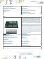
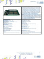
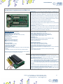
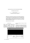
CONTROL UNIT IO-69 USER MANUAL Rel. 01.05.0000 (Hardware code: IO-69-U) 1 www.ipses.com IO69 USER MANUAL _____________________________ All information provided in this manual is property of IPSES S.r.l. and must be considered and treated as confidential. Any reproduction, transmission, copy or translation into any human or computer language of this publication is forbidden, unless specifically approved by IPSES S.r.l. in writing. All information in this document has been carefully checked and is believed to be accurate as of the date of publication; however, no responsibility is assumed in case of incorrectness. IPSES will not be liable for any consequential or incidental damages arising from reliance on the accuracy of this documentation. The information contained in this manual is subject to change without notice and does not represent a commitment on the part of IPSES. IPSES is committed to continuous development and quality improvement of its products. As a consequence, the equipment described in this document may incorporate minor differences from what described hereafter. Please, consult IPSES technical support to receive any specific updated information for your product. All brand or product names are trademarks or registered trademarks of their respective holders. This manual in English is the original version. Printed in Italy Copyright 2006-2015 IPSES S.r.l. All rights reserved. IPSES S.r.l. Via Lazzarotto, 10 - 20020 Cesate (MI) - ITALY Tel. (+39) 02/39449519 Fax (+39) 02/700403170 http://www.ipses.com e-mail [email protected] 2 IO69 USER MANUAL GUARANTEE IPSES warrants to the end-user in accordance with the following provisions that its branded hardware products, purchased by the end-user from IPSES company or an authorized IPSES distributor are free from defects in design, materials, and workmanship affecting normal use, for a period of one year as of the original delivery date. At IPSES’s option, products for which proper claims are made will be repaired or replaced at IPSES’s expense1. Exclusions This Guarantee does not apply in case of defects resulting from: improper or inadequate installation, use, or maintenance; actions or modifications by unauthorized third parties or the end-user; accidental or wilful damage or normal wear and tear. Making a claim Claims must be made by contacting IPSES office within the guarantee period. Please, contact: IPSES S.r.l. – Via Lazzarotto, 10 - 20020 Cesate (MI) Italy Tel. (+39) 02/39449519 – (+39) 02 320629547 Fax (+39) 02/700403170 http://www.ipses.com – e-mail: [email protected] Limitation and Statutory Rights IPSES makes no other warranty, guarantee or like statement other than as explicitly stated above and this Guarantee is given in place of all other guarantees whatsoever, to the full extent permitted by law. In the absence of applicable legislation, this Guarantee will be the end-user’s sole and exclusive remedy against IPSES. General Provisions IPSES makes no express warranties or conditions beyond those stated in this warranty statement. IPSES disclaims all other warranties and conditions, express or implied, including without limitation implied warranties and conditions of merchantability and fitness for a particular purpose. IPSES’s responsibility for malfunctions and defects in hardware is limited to repair and replacement as set forth in this warranty statement. IPSES does not accept liability beyond the remedies set forth in this warranty statement or liability for incidental or consequential damages, including without limitation any liability for products not being available for use or for lost data or software. 1 With the exclusion of shipping costs for and from IPSES’s laboratories. IPSES S.r.l. Via Lazzarotto, 10 - 20020 Cesate (MI) - ITALY Tel. (+39) 02/39449519 Fax (+39) 02/700403170 http://www.ipses.com e-mail [email protected] 3 IO69 USER MANUAL WARNING! ELECTRICAL DEVICES MAY DAMAGE EQUIPMENT OR PROPERTY OR CAUSE PERSONAL INJURY This guide contains instructions and technical features of the IO-69 CONTROL UNIT. Read carefully before attempting to install and use this device. It is the responsibility of the technician to undertake all the safety rules provided by law and standard practice during the installation and the use of this device. For any information which is not contained in this guide, please contact: IPSES S.r.l. - – Via Lazzarotto, 10 - 20020 Cesate (MI) Italy Tel. (+39) 02/39449519 – (+39) 02 320629547 Fax (+39) 02/700403170 http://www.ipses.com – e-mail [email protected] IPSES S.r.l. Via Lazzarotto, 10 - 20020 Cesate (MI) - ITALY Tel. (+39) 02/39449519 Fax (+39) 02/700403170 http://www.ipses.com e-mail [email protected] 4 IO69 USER MANUAL TABLE OF CONTENTS REVISION HISTORY .......................................................................................................................................................... 6 GENERAL FEATURES ....................................................................................................................................................... 7 DRIVER INSTALLATION .................................................................................................................................................... 8 REMOTE CONTROL COMMUNICATION PROTOCOL ................................................................................................... 12 LAYOUT ............................................................................................................................................................................ 15 OUTPUT LINES............................................................................................................................................................ 17 INPUT LINES................................................................................................................................................................ 19 DEMO SOFTWARE .......................................................................................................................................................... 22 INSTALLATION ............................................................................................................................................................ 22 EXECUTION ................................................................................................................................................................. 22 FUNCTIONS ................................................................................................................................................................. 23 CONNECTION TO IO-69 DEVICE ............................................................................................................................... 25 EXAMPLE USING THE DLL ............................................................................................................................................. 28 LabVIEW LIBRARY........................................................................................................................................................... 31 TECHNICAL SPECIFICATIONS ....................................................................................................................................... 33 ORDERING INFORMATION ............................................................................................................................................. 34 OTHER AVAILABLE I/O CARDS ...................................................................................................................................... 35 CONTACTS ...................................................................................................................................................................... 41 SUPPORT INFORMATION ............................................................................................................................................... 42 PROBLEM REPORTING .................................................................................................................................................. 42 ENGINEERING PROBLEM REPORT............................................................................................................................... 43 IPSES S.r.l. Via Lazzarotto, 10 - 20020 Cesate (MI) - ITALY Tel. (+39) 02/39449519 Fax (+39) 02/700403170 http://www.ipses.com e-mail [email protected] 5 IO69 USER MANUAL REVISION HISTORY Manual revision history Revisione/ Data 01.00.0000 October, 2006 01.02.0000 January, 2009 01.03.0000 June, 2009 Descrizione modifica Autore First version Released Dugato S. Minor editorial corrections Liguori C., Rivolta A. 01.04.0000 October, 2010 01.05.0000 January, 2012 01.05.0001 March, 2015 Updated Driver Installation chapter, specified full Zancanato A. buffer error condition, added WEB-ADIO description Updated technical data, added picture for Rivolta A. polarization of the inputs. Minor editorial corrections. Updated contacts data, minor changes Mancuso Added an example of use DLL D2XX and other Zancanato minor editorial corrections. Minor editorial Mancuso C. corrections IPSES S.r.l. Via Lazzarotto, 10 - 20020 Cesate (MI) - ITALY Tel. (+39) 02/39449519 Fax (+39) 02/700403170 http://www.ipses.com e-mail [email protected] A., 6 IO69 USER MANUAL GENERAL FEATURES IO-69 is a digital input/output control unit with an USB interface, implemented on an European Card Format (160 x 100 mm). IO-69 can read six independent input lines and control nine independent output lines. All the digital lines are electrically unconnected and can be referenced to a separate ground return. Input lines are galvanically insulated by using optocouplers, while output lines are controlled by relays (ST is standard delivery, DT option is available on demand). Each input line can be individually configured for a different input mode and voltage range, from 5 to 24 Vdc. The reference voltages for the input and output sections are independent. A safety feature can be programmatically implemented to ensure protection and safety to the instruments wired to the IO-69: when no command is sent to the device within a settable time interval, the unit will enter an idle condition and deactivate all the output lines. An output line is defined active when the relay controlling it is energized. Furthermore, it is possible to configure each individual output line to become active only when predefined input lines reach assigned conditions: in this case, the IO-69 unit becomes a simple programmable logic controller. The device can be completely configured through the USB interface by a Windows based PC using the software configuration tool distributed with the unit. IPSES S.r.l. Via Lazzarotto, 10 - 20020 Cesate (MI) - ITALY Tel. (+39) 02/39449519 Fax (+39) 02/700403170 http://www.ipses.com e-mail [email protected] 7 IO69 USER MANUAL DRIVER INSTALLATION We recommend to execute the automatic software installation from CD before connecting the device to PC. By this way software and USB driver are both installed, allowing the PC to automatically identify the device once you connect it. If you use the recommend automatic software installation from CD, you do not need to follow indications contained in this chapter. If you do not use the recommend automatic software installation from CD, to connect IO-69 to your PC you need to install only the USB IPSES driver that is certified for the most recent Microsoft operating systems: - Microsoft Windows 2000 family - Microsoft Windows XP family, x86 - Microsoft Windows Server 2003 family, x86 - Microsoft Windows Server 2003 family, x64 - Microsoft Windows XP family, x64 - Microsoft Windows Vista family, x86 - Microsoft Windows Vista family, x64 - Windows Server 2008 family, x86 - Windows Server 2008 family, x64 –Windows 7 - Windows 7 x64 - Windows 8 and 8.1 family - Windows Server 2008 Release 2 family, x64 If your PC has an Internet connection, you should follow the automatic Windows Update procedure; otherwise follow the manual installation procedure from CD. IPSES S.r.l. Via Lazzarotto, 10 - 20020 Cesate (MI) - ITALY Tel. (+39) 02/39449519 Fax (+39) 02/700403170 http://www.ipses.com e-mail [email protected] 8 IO69 USER MANUAL Automatic Windows Update procedure 1) Connect the IO-69 board to PC using a USB cable. Windows operating system will detect a new device, showing a message similar to: 2) In the following windows “found new hardware wizard” chose “Yes, this time only” and then “Next”. 3) Then choose “install the software automatically (Recommended)” and then “Next”. Wait for downloading of the driver and its installation. 4) Installation is completed when the window on the left is displayed. Choose “Finish” to exit. 5) After a window with the message “Found New Hardware. USB Serial Port” is displayed. Follow again instruction from point 2) Manual driver installation procedure IPSES S.r.l. Via Lazzarotto, 10 - 20020 Cesate (MI) - ITALY Tel. (+39) 02/39449519 Fax (+39) 02/700403170 http://www.ipses.com e-mail [email protected] 9 IO69 USER MANUAL 1) Connect the IO-69 board to the PC using a USB cable. Windows operating system will detect a new device, showing the message: 2) In the following windows “found new hardware wizard” “No, not this time” and then “Next”. chose 3) Then choose “install from a list or specific location (Advanced)” and “Next”. Then Set the driver folder path on the CD. IPSES S.r.l. Via Lazzarotto, 10 - 20020 Cesate (MI) - ITALY Tel. (+39) 02/39449519 Fax (+39) 02/700403170 http://www.ipses.com e-mail [email protected] 10 IO69 USER MANUAL 4) The Successful of the installation is indicated by the message of completing the found new hardware wizard. To end, click "Finish". 5) After installation of the hardware described above, the new device "USB Serial Port" is detected. Follow again instruction from point 2). IPSES S.r.l. Via Lazzarotto, 10 - 20020 Cesate (MI) - ITALY Tel. (+39) 02/39449519 Fax (+39) 02/700403170 http://www.ipses.com e-mail [email protected] 11 IO69 USER MANUAL REMOTE CONTROL COMMUNICATION PROTOCOL The IO-69 unit is completely controlled through a USB port by using a simple proprietary communication protocol. The commands are text strings in ASCII code, terminated with the <CR> character. The protocol is case insensitive. If you send ten characters without termination <CR>, the device sends the error string “E ” and ignores the last ten characters. IO-69 unit can be controlled using any serial communication client (like Windows HyperTerminal): to do this, use the com port number assigned to your virtual com. Application programs may be developed using the standard serial communication device driver functions. In this case, use the following communication settings: Bits per second: 9600 baud Data bits: 8 Parity: none Stop bit: 1 Flow control: hardware (CTS, RTS) Alternatively, application programs may be developed using the low level communication library “FT2XX.dll”. In this case, please refer to the manual “FTD2XX.DLL DYNAMIC LIBRARY” by IPSES which is available in the documentation CD provided with the card or can be downloaded from the website at the following link: http://www.ipses.com/PDF/IPSESD2XX-en.pdf. The following commands are recognized by the IO-69 unit: Requests the current global status of the unit (See below how the status is coded). U Requests the version firmware and the serial number of the device. The response is a string in ASCII code similar to ? Ax Sx Cxx LnI1I2I3I4I5I6 LnC LC L? “IO-69 USB – vx.x – S/Nyyyyyy – www.ipses.com”, where x.x represents the firmware version and yyyyyy the serial number of the unit. Activates the output line x. x is a number between 1 and 9: output x is activated; let x = A to activate all outputs at the same time. This command overrides and disables, if active, any logical x output setting (see the command LnI1I2I3I4I5I6 below). Disables the output line x. x is a number between 1 and 9: output x is disabled; let x = A to deactivate all outputs at the same time. This command overrides and disables, if active, any logical x output setting (see the command LnI1I2I3I4I5I6 below). Sets simultaneously outputs 2 to 9 to the status defined by xx. xx is a two digit number representing the desired output lines status in hexadecimal notation, where bit 0, 1, .. correspond to the output line 2, 3, … For example, C01 activates output 2 and deactivates all the other lines, C80 activates output 9; C81 activates both output 2 and 9. This command forces the status of any logical output line (2 to 9) to the value selected, overriding any other setting by different commands (see following LnI1I2I3I4I5I6 command). The status of the output line 1 is unaffected by this command. Logical output line setting. Activates the n output only when logical Ii conditions are verified at the same time. I can be a value between 1 and 6. and identifies the correspondent input. Ii can be 1 (logical true, Vcc), 0 (logical false, Vref), or X (logical don’t care). Deactivates logical n output setting (see LnI1I2I3I4I5I6 command). Deactivates each logical output setting (see LnI1I2I3I4I5I6 command). Requests the logical output setting. The response is a string in ASCII code similar to “1-111001;2-00XXX1;3-------;4000000;5-111111;6-------;7-------;8-------; 9------;”. For each output, numbered from 1 to 9, logical Ii input conditions are displayed (see LnI1I2I3I4I5I6 command). IPSES S.r.l. Via Lazzarotto, 10 - 20020 Cesate (MI) - ITALY Tel. (+39) 02/39449519 Fax (+39) 02/700403170 http://www.ipses.com e-mail [email protected] 12 IO69 USER MANUAL Tt T? M F Sets the timeout interval: if no command is received within the set interval, all the output lines are deactivated. The timeout is set with t. t = 0: no timeout – feature not active; t = 1: 3 seconds timeout. t = 2: 5 seconds timeout. t = 3: 10 seconds timeout. t = 4: 30 seconds timeout. t = 5: 1 minute timeout. t = 6: 5 minutes timeout. t = 7: 10 minutes timeout. t = 8: 30 minutes timeout. t = 9: 1 hour timeout. Requests the timeout setting. The response is an ASCII char from 0 to 9 representing the current setting as per the command Tt. Saves in memory the current configuration (timeout and logical output lines setting) Loads from memory the saved configuration (timeout and logical output lines setting) The status request message (“U”) forces the device to return a 2-byte value (4 hex characters) representing the status of the unit according to the following table: bit 15 bit 14 bit 13 bit 12 bit 11 bit 10 bit 9 bit 8 bit 7 bit 6 bit 5 bit 4 bit 3 bit 2 bit 1 bit 0 Output 9 status Output 8 status Output 7 status Output 6 status Output 5 status Output 4 status Output 3 status Output 2 status Output 1 status Input 6 status Input 5 status Input 4 status Input 3 status Input 2 status Input 1 status Error When the error bit (bit 0) is set, an error code follows the status value, separated by a comma (i.e. 8001,02); the error code is a 1-byte value (2 hex characters) representing the error condition(s) according to the following table: bit 7 bit 6 bit 5 bit 4 bit 3 bit 2 bit 1 bit 0 Unused Unused Unused Saved configuration inconsistent: using factory default settings Internal EEPROM checksum error Timeout condition Illegal command Unrecognized command IPSES S.r.l. Via Lazzarotto, 10 - 20020 Cesate (MI) - ITALY Tel. (+39) 02/39449519 Fax (+39) 02/700403170 http://www.ipses.com e-mail [email protected] 13 IO69 USER MANUAL A status request command (U) resets an error condition, if present. If an external power supply is used, it is recommended to connect the USB cable only after providing the power to the unit. IPSES S.r.l. Via Lazzarotto, 10 - 20020 Cesate (MI) - ITALY Tel. (+39) 02/39449519 Fax (+39) 02/700403170 http://www.ipses.com e-mail [email protected] 14 IO69 USER MANUAL LAYOUT The following sketch shows the IO-69 layout: the nine outputs, numbered from 1 to 9, are in the upper part of the card; the six inputs, from 1 to 6, are in the right part of the card. Moreover, there is an area (“OPTIONAL” is clearly readable) on which further components, eventually requested, may be allocated in order to implement more functionalities. Jumpers Outputsss Optional Inputs Picture 1: IO-69 layout. Figure 1 shows also the input voltage jumper selectors (J3, J4, J5, J6, J7, J8) which allow to set the correct input voltage Vcc for each input line to 5 V, 12 V and 24 V. The picture 2 displays input and output status leds. When leds are on, they indicate: D1 Red LED. Packet excange on USB port D2 Green LED. Connection to PC happened and driver correctly loaded IPSES S.r.l. Via Lazzarotto, 10 - 20020 Cesate (MI) - ITALY Tel. (+39) 02/39449519 Fax (+39) 02/700403170 http://www.ipses.com e-mail [email protected] 15 IO69 USER MANUAL D50 D34 D35 D37 D39 D41 D43 D13 D12 D11 D10 D9 D8 D7 D6 D5 Red LED show an error state LED on, Vcc applied at IN 1 LED on, Vcc applied at IN 2 LED on, Vcc applied at IN 3 LED on, Vcc applied at IN 4 LED on, Vcc applied at IN 5 LED on, Vcc applied at IN 6 LED on, OUT 1 is active LED on, OUT 2 is active LED on, OUT 3 is active LED on, OUT 4 is active LED on, OUT 5 is active LED on, OUT 6 is active LED on, OUT 7 is active LED on, OUT 8 is active LED on, OUT 9 is active OUT9 OUT8 OUT7 OUT6 OUT5 OUT4 OUT3 OUT2 OUT1 Error LED IN1 IN2 IN3 IN4 LEDs on: output is activated IN5 IN6 LEDs on: input Vcc applied Status LEDs of USB communication Picture 2: LEDs. IPSES S.r.l. Via Lazzarotto, 10 - 20020 Cesate (MI) - ITALY Tel. (+39) 02/39449519 Fax (+39) 02/700403170 http://www.ipses.com e-mail [email protected] 16 IO69 USER MANUAL OUTPUT LINES The nine output lines are completely insulated, both between them and with other electrical components of the device. In fact, each output is constituted by a double-throw relay (unit code IO69-USB-SPDT), as indicated here below: Picture 3: electric diagram of the output section for the double-throw output model. Alternatively, each output is constituted by a single-throw relay (unit code IO69-USB-SPST), as indicated here below: Picture 4: electric diagram of the output section for the single-throw output model. IPSES S.r.l. Via Lazzarotto, 10 - 20020 Cesate (MI) - ITALY Tel. (+39) 02/39449519 Fax (+39) 02/700403170 http://www.ipses.com e-mail [email protected] 17 IO69 USER MANUAL Here below there are the pictures of the two different models: figure 5a shows model with SPST relays, while figure 5b shows model with SPDT relays. Picture 5a: IO69-USB-SPST. Picture 5b: IO69-USB-SPDT. The status of each output line is displayed by a LED located near its respective output connector. a) OUT1, OUT3, OUT5, OUT7, OUT 9 are activated. b) OUT2, OUT4, OUT6, OUT8 are activated. c) All outputs activated. Picture 6: different output lines configuration. The electrical specifications of the output lines are : Maximum current: 0,5 A (IO69-USB-SPDT) Maximum current: 1 A (IO69-USB-SPST) Maximum voltage: 100 VDC. Minimum insulation between reel and contacts: 1000 VDC. The output line average life time, in worst case (always using nominal switching current), is between 100.000 and 1.000.000 switches. IPSES S.r.l. Via Lazzarotto, 10 - 20020 Cesate (MI) - ITALY Tel. (+39) 02/39449519 Fax (+39) 02/700403170 http://www.ipses.com e-mail [email protected] 18 IO69 USER MANUAL Using current lower than the nominal one, the guaranteed cycles are more than 500.000.000. Using loads with high capacity or inductance, with peak current over the nominal value, the outputs line life time may reduce considerably. INPUT LINES All input lines are galvanically insulated, both between them and from other electrical components of the device. The minimum insulation voltage is 500 V. The input voltage range is set independently for each input line by means of the jumper selectors (J3, J4, J5, J6, J7, J8). Possible choices are 5 VDC, 12 VDC and 24 VDC. The following picture shows different examples of jumper position. a) jumper positions for 5 V at each input. b) jumper positions for 12 V at each input. c) jumper positions for 24 V at each d) jumper positions in case of voltage input for IN1, IN2, IN3, IN4, IN5, IN6 severally is 5 V, 24 V, 5 V, 12 V, 24 V, 24 V. e) jumper positions in case of voltage input for IN1, IN2, IN3, IN4, IN5, IN6 severally is 5 V, 24 V, 24 V, 24 V, 12 V, 12 V. f) jumper positions in case of voltage input for IN1, IN2, input. IN3, IN4, IN5, IN6 severally is 24 V, 24 V, 12 V, 24 V, 24 V, 5 V. Picture 7: different jumper position examples; all inputs are galvanic insulated and not correlated. The input line circuitry is shown by the electrical diagram in picture 8a here below, while in picture 8b is shown the correct polarization scheme for the inputs. IPSES S.r.l. Via Lazzarotto, 10 - 20020 Cesate (MI) - ITALY Tel. (+39) 02/39449519 Fax (+39) 02/700403170 http://www.ipses.com e-mail [email protected] 19 IO69 USER MANUAL Picture 8a: electrical diagram of a logical input. Picture 8b: polarization scheme for the inputs. Each input line status is displayed by a LED located near each input connector. IPSES S.r.l. Via Lazzarotto, 10 - 20020 Cesate (MI) - ITALY Tel. (+39) 02/39449519 Fax (+39) 02/700403170 http://www.ipses.com e-mail [email protected] 20 IO69 USER MANUAL a) IN1, IN3, IN5 active. b) IN2, IN4, IN6 active. c) All inputs are active. Picture 9: example of different input conditions. The electrical specifications of the input lines are: Input voltage jumper-settable to 5, 12, or 24VDC. Minimum operating insulation: 2500VRMS. IPSES S.r.l. Via Lazzarotto, 10 - 20020 Cesate (MI) - ITALY Tel. (+39) 02/39449519 Fax (+39) 02/700403170 http://www.ipses.com e-mail [email protected] 21 IO69 USER MANUAL DEMO SOFTWARE IO-69_Demo is a demo application allowing full remote control and testing of IO-69 unit. The virtual instrument panel offers intuitive functions, which allow the user to quickly and easily understand the unit’s operation. INSTALLATION The demo application can be installed on your PC by double-clicking on “Installer_IO-69_Demo.exe” and following the instructions displayed. The executable file “IO-69_Demo.exe” will be installed in the default program files directory, in the folder “IO-69_Demo”. EXECUTION Execute “IO-69_Demo.exe”. A control panel is displayed as shown in picture 10. Picture 10: virtual control panel. IPSES S.r.l. Via Lazzarotto, 10 - 20020 Cesate (MI) - ITALY Tel. (+39) 02/39449519 Fax (+39) 02/700403170 http://www.ipses.com e-mail [email protected] 22 IO69 USER MANUAL FUNCTIONS The graphical interface is structured to allow user an easy understanding of the different implemented functions. The upper area of the panel allows the selection of the mode and the monitoring of the connection by visualizing status and/or error messages. The central section of the virtual panel allows the direct monitoring and control of the IO-69 lines: the row of LEDs labelled as IN1, …, IN6 shows the current status of the input lines, while the line of LEDs labelled as OUT1, OUT2, …, OUT9 shows the nine output lines status. The two pushbuttons Switch on all and Switch off all allow respectively to activate or to deactivate all the nine output lines of the device at the same time. The pushbutton Refresh Status updates the indicators and selectors status presented on the panel. The Set Timeout pushbutton allows the user to set for each board the respective communication timeout. When its timeout expires without receiving any command, the unit resets to the power-on status until a new command is received. The bottom part of the virtual panel is reserved to the sequential and parallel programming of the output lines. (Sequential Out Management and Parallel Out Management, respectively) as displayed by pictures 11 and 12, as well as the set up of the programmable logic that control the output lines status as a function of the input line status (Logic Out Management). Picture 11: setup tab for the Sequential Programming of the output lines Picture 12: setup tab for the Parallel Programming of the output lines IPSES S.r.l. Via Lazzarotto, 10 - 20020 Cesate (MI) - ITALY Tel. (+39) 02/39449519 Fax (+39) 02/700403170 http://www.ipses.com e-mail [email protected] 23 IO69 USER MANUAL In the Logic Out Management tab shown in picture 13 (see here below), Output represents the id 1, …, 9 of the output line to be activated when the values of the six input lines match the pattern (0, 1, or X (don’t care)). Each single output line can be programmed by clicking on the button Program. Its existing program can be cleared by clicking on the button Clear, while pressing the button Clear All any programming present on the device will remove. The current program settings can be saved in the non-volatile memory by clicking on the button Save, while clicking on Load any program previously saved will be reload from the memory. Picture 13: panel for the logical programming of the outputs. The following section of the control panel represents the logical output programming status. Picture 14: output programming status; green light indicates which one of the output lines is active. The Sequential Out Management allows to setup an initial configuration of the nine output lines – see picture 15. After a cycle time equal to Step Time S1, …, Step Time S9 expressed in milliseconds, the status of the output line identified in the field Out1, …, Out 9 will change. Similarly, the program Parallel Out Management allows to configure the simultaneous activation or deactivation of the nine output lines when the respective cycle time is elapsed. Picture 15: output settings; green light indicates which one of the outputs is activated. The program settings in the tabs Sequential Out Management and Parallel Out Management can be saved in the nonvolatile memory and reloaded by using the buttons Save program and Open program, respectively. IPSES S.r.l. Via Lazzarotto, 10 - 20020 Cesate (MI) - ITALY Tel. (+39) 02/39449519 Fax (+39) 02/700403170 http://www.ipses.com e-mail [email protected] 24 IO69 USER MANUAL CONNECTION TO IO-69 DEVICE In the field Model selection, located in the upper left side of the virtual control panel, it is possible to select the desired communication interface. Model selection Working mode IO-69_USB_VCP Uses a virtual serial port allowed by the driver IO-69_USB_D2XX Uses directly the USB communication Once the desired communication mode is selected, thorugh the Connect button is possible to start a communication session (the status is shown by the LED Working connection). Through Info device, the IO-69 returns information about its firmware version and serial number. Picture 16: output selectors. Once the communication is active, output selectors (see picture 16), output lines programming panel (figure 9) and the following commands will be enabled: Switch on all Switchs on all output selectors at the same time Switch off all Switchs off all output selectors at the same time Executes the program as set in the Sequential Out Management tab Executes the program as set in the Parallel Out Management tab Stops program execution Execute Sequential Program Execute Parallel Programming Stop execution Save program Advanced Saves in non-volatile memory the current program settings Loads from non-volatile memory the program settings previously stored Advanced subroutine execution Set timeout Sets the timeout Open program All possible error conditions are displayed. For example, picture 17 shows the displayed message when the communication with an IO-69 unit is not established. Picture 17: error event example. To come back to application operation, it is necessary Click on RESET. IPSES S.r.l. Via Lazzarotto, 10 - 20020 Cesate (MI) - ITALY Tel. (+39) 02/39449519 Fax (+39) 02/700403170 http://www.ipses.com e-mail [email protected] 25 IO69 USER MANUAL Advanced runs homonym subroutine, as shown in picture18. Picture 18: Advanced subroutine. The Advanced subroutine allows user a lower level management of the IO-69 unit, both to send commands and to query card for. To send commands the following fields are available: Command: allows the selection of the command to be sent. par: allows to set the parameter of the command to be sent. Run Send: sends the command To query the card, the following fields are available: Question: allows the selection of the query to be sent Run Read: allows to get answers to the previous selected queries by Question. IPSES S.r.l. Via Lazzarotto, 10 - 20020 Cesate (MI) - ITALY Tel. (+39) 02/39449519 Fax (+39) 02/700403170 http://www.ipses.com e-mail [email protected] 26 IO69 USER MANUAL UNINSTALLATION To correctly uninstall the software, follow the instructions listed below. 1) From the Start menu, click “Control Panel”. 2) Click “Add or Remove Programs” from the resource list displayed. 3) From the list of installed programs select “IO-69_Demo” and proceed to removal by clicking “Change/Remove”. IPSES S.r.l. Via Lazzarotto, 10 - 20020 Cesate (MI) - ITALY Tel. (+39) 02/39449519 Fax (+39) 02/700403170 http://www.ipses.com e-mail [email protected] 27 IO69 USER MANUAL EXAMPLE USING THE DLL The following example allows to open the communication (to the indexed device by device_index=0), to read the firmware and serial number ( “?” command), to set all outputs ( “AA” command), to get the system status (“U” command) and to close the communication. // Variables definition unsigned long ftStatus = 0, ftHandle = 0; unsigned long TxBytes = 0, RxBytes = 0, EventNode = 0, BytesWritten = 0, BytesReceived = 0; char TxBuffer [16] = “ ”; char RxBuffer [256] = “ ”; UCHAR p1,p2; p1=0; p2=0; // Open Device Communication to 0 indexed device and sets its communication parameters ftStatus = FT_Open (0, &ftHandle); if (ftStatus != FT_OK) { //Error on opening procedure } else { ftStatus = FT_SetBaudRate (ftHandle, 9600); if (ftStatus != FT_OK) { //Error on setting baud rate procedure } else { ftStatus = FT_SetDataCharacteristics (ftHandle, FT_BITS_8, FT_STOP_BITS_1, FT_PARITY_NONE ); if (ftStatus != FT_OK) { //Error on setting data characteristics procedure } else { ftStatus = FT_SetFlowControl (ftHandle, FT_FLOW_RTS_CTS,p1, p2); if (ftStatus != FT_OK) { //Error on setting flow control procedure } else { ftStatus = FT_SetTimeouts (ftHandle, 500, 300); if (ftStatus != FT_OK) IPSES S.r.l. Via Lazzarotto, 10 - 20020 Cesate (MI) - ITALY Tel. (+39) 02/39449519 Fax (+39) 02/700403170 http://www.ipses.com e-mail [email protected] 28 IO69 USER MANUAL { //Error on setting timeout procedure } else { //Opening procedure successfully completed } } } } } //Get Info device TxBuffer = “?/r”; ftStatus = FT_Write (ftHandle, TxBuffer, 2, &BytesWritten); if (ftStatus != FT_OK){ { //Write error } else { FT_GetStatus(ftHandle, &RxBytes); if (RxBytes >0 ) { ftStatus = FT_Read(ftHandle, RxBuffer, RxBytes, &BytesReceived); if (ftStatus == FT_OK) { // successfully reading } else { // Error reading } } } //Send command: AA TxBuffer = “AA/r”; ftStatus = FT_Write (ftHandle, TxBuffer, sizeof(TxBuffer), &BytesWritten); if (ftStatus != FT_OK){ { //Write error } else { //Command sent } IPSES S.r.l. Via Lazzarotto, 10 - 20020 Cesate (MI) - ITALY Tel. (+39) 02/39449519 Fax (+39) 02/700403170 http://www.ipses.com e-mail [email protected] 29 IO69 USER MANUAL //Get status TxBuffer = “u/r”; ftStatus = FT_Write (ftHandle, TxBuffer, 2, &BytesWritten); if (ftStatus != FT_OK){ { //Write error } else { FT_GetStatus(ftHandle, &RxBytes); if (RxBytes >0 ) { ftStatus = FT_Read(ftHandle, RxBuffer, RxBytes, &BytesReceived); if (ftStatus == FT_OK) { // Status successfully reading } else { // Error reading } } } //Close device FT_Close (ftHandle); The CD attached to the board includes the source code of an example project for the communication with the DLL, developed for both LabWindows/CVI (National Instruments) and Visual C#. IPSES S.r.l. Via Lazzarotto, 10 - 20020 Cesate (MI) - ITALY Tel. (+39) 02/39449519 Fax (+39) 02/700403170 http://www.ipses.com e-mail [email protected] 30 IO69 USER MANUAL LabVIEW LIBRARY The module LabView_IO-69_Library is available on demand. For users desiring to realize their application for IO-69 card remote control through LabVIEW, IPSES developed a specific library fully compatible with LabVIEW 7.1 and all the following versions. To use the LabView_IO-69_Library it is necessary to install the LabVIEW RunTime Engine 7.1(or later) and, in case of use of the serial communication protocol (VCP) too, the NI VISA RunTime 4.20 (or later). The library make available to user nine functions through with it is possible to implement any application software in LabVIEW in a quick and easy way, because it will be not necessary to know all the detail of the communication protocol. The library functions are divided into two levels: IO-69_Low_Level_Communication.llb contains the four functions through which it is possible to manage the connection with the IO69 card. IO-69_Application.llb contains the five higher level functions (based on the low level functions), which allow the commands assignment accepted from the device. The use of the IO-69_Application.llb is deemed enough for most application development, while IO69_Low_Level_Communication is to be used to maximize performances. IO-69_Low_Level_Communication.llb IO-69_Application.llb Function Properties Close_Device.vi Closes the connection established with one of the available protocols. Open_Device.vi Opens the connection with one of the available protocols. Write&Read.vi Sends and receives ASCII characters. Write_Command.vi Sends ASCII characters. Close_dialogue.VI Ends the communication with the IO-69 card. Read.vi Interprets characters sent by the device. Return_Info.vi Drafts the S/N list of connected devices. Send_Command.vi Imparts the commands implemented on the device. Start_dialogue.vi Starts dialogue session with the IO-69 card. LabView_IO-69_Library comes with an help file, IO-69_Help.chm. The help file provides a detailed explanation and a structural description of all the nine functions contained in the library. Graphical representations are included, so that the user may easily understand how they work in the tool in which they are built. Next figure displays the help of the library. IPSES S.r.l. Via Lazzarotto, 10 - 20020 Cesate (MI) - ITALY Tel. (+39) 02/39449519 Fax (+39) 02/700403170 http://www.ipses.com e-mail [email protected] 31 IO69 USER MANUAL Picture 19: LabView functions help. You can find more information at www.ipses.com . IPSES S.r.l. Via Lazzarotto, 10 - 20020 Cesate (MI) - ITALY Tel. (+39) 02/39449519 Fax (+39) 02/700403170 http://www.ipses.com e-mail [email protected] 32 IO69 USER MANUAL TECHNICAL SPECIFICATIONS Power supply: control logic directly powered through the computer USB port Operating temperature range: 0°C ~ +60°C. Non-operating temperature range: -40°C ~ +85°C. Input lines: six optocoupled input lines with input voltage range individually selectable among 5/12/24 VDC. Average reading time ("U" command): 12ms Input lines insulation voltage: 2500VRMS. Output lines (SPDT): nine output lines with single pole – double throw contact Max switching current: 0,25A Max carrying current: 0,5A Max switching voltage: 70Vac/100Vdc, potential free Max contact resistance: 200mΩ Output lines (SPST): nine output lines with single pole – single throw contact Max switching current: 0,5A Max carrying current: 1A Max switching voltage: 100Vac/dc, potential free Max contact resistance: 150 mΩ Reel to contact insulation: 1000 VDC Insulation resistance (coil/contact): 10Gohm USB interface: USB port type B, USB2.0 compatible Board dimensions: 100 x 160 mm (3,94 x 6,30 inches) Thickness (included components): 15 mm (0.59 inches) Spacing of the mounting holes: 90 mm x 150 mm (3,55 x 5,91 inches) Diameter holes for M3 screw The outputs line average life time, in worst case (always using nominal switching current), is between 100.000 and 1.000.000 switch. Using current lower than the nominal, the guaranteed cycles are more than 500.000.000. Using load with high capacity or inductance, with peak current over the nominal value, the outputs line life time may reduce considerably. IPSES S.r.l. Via Lazzarotto, 10 - 20020 Cesate (MI) - ITALY Tel. (+39) 02/39449519 Fax (+39) 02/700403170 http://www.ipses.com e-mail [email protected] 33 IO69 USER MANUAL ORDERING INFORMATION Code IO69-USB-SPST IO69-USB-SPDT IO69-USB-SPST-DIN IO69-USB-SPDT-DIN IO69Library USB-A-B USB-A-B-ill Description Control board with SPST relay output Control board with SPDT relay output Control board with SPST relay output, board mounted on DIN rail support Control board with SPDT relay output, board mounted on DIN rail support LabView 7.1 (and following versions) Library for IO-69-USB cards USB connection cable USB connection cable, with light on termination IPSES S.r.l. Via Lazzarotto, 10 - 20020 Cesate (MI) - ITALY Tel. (+39) 02/39449519 Fax (+39) 02/700403170 http://www.ipses.com e-mail [email protected] 34 IO69 USER MANUAL OTHER AVAILABLE I/O CARDS IO-1616: Input/output Card with 16 inputs and 16 outputs and USB interface IO1616 is a self powered card to manage sixteen optoisolated inputs and sixteen optoisolated outputs with USB interface. IO1616 can be directly connected to PLC, to input devices from operator and to other I/O systems. On request, an integrated temperature sensor allows to know in real time the temperature of the system IO1616 is placed in. General technical features: Power supply: self-powered thorugh USB Working temperature: from 0°C up to + 60°C Storage temperature: from -40°C up to + 85°C Size: European format card (100 x 160 mm - 3,94 x 6,30 inches) USB port technical features: 1 type B port, compatible with USB 2.0, autonomously powered for the host connection - Possibility to connect directly to an host port up to 128 cards, cards for a maximum of 2.048 inputs and 2.048 outputs Temperature sensor technical features: Resolution: 0,0625°C Accuracy: from ±1°C to ±3°C, depending on temperature range. Technical features of inputs: Number of inputs: sixteen Operative voltage: from 3,3VDC up to 36VDC Max current absorbed: 10mA (on each input) Input impedance: ≈ 2.5KΩ Logic low level: < 1V Logic high level: > 2.5V Port read average time execution: 15 ms Protection: optocouplers with 2.500VRMS maximum operative voltage Connectors: pitch terminal block Technical features of outputs: Number of outputs: sixteen Operative voltage: from 3,3VDC up to 36VDC Maximum current: 150 mA Protection: optocouplers with 2.500VRMS maximum operative voltage Connectors: pitch terminal block Timeout control to turn off all the outputs if it does not receive commands from the host within a time configurable through software. CAN-IO: Input/output Card with 16 inputs and 16 outputs with CAN, USB and RS232 interface CAN-IO is a control unit equipped with CAN, USB and RS232 interfaces to manage sixteen optocoupled inputs and outputs. The card can work as standalone device on CAN BUS. Its configuration is achieved either through USB (in this case the board is self powered) or through RS232 interface. Easy to use and to configure, thanks to the provided software, CAN-IO is the right answer to the need to acquire and to drive digital signals through already existing CAN bus. CAN-IO can be directly connected to PLC, to input devices by operator and to other I/O systems. Each input and output status can be read by a field bus at any moment. Besides, thanks to LEDs fixed on, the status is shown directly on the board. An integrated temperature sensor allows to know in real time the temperature of the system CAN-IO is placed in. General technical features: Power supply: self-powered through USB or +5VDC in stand-alone mode Working temperature: from 0°C up to + 60°C Storage temperature: from -40°C up to + 85°C Size: European format card (100 x 160 mm - 3,94 x 6,30 inches) Interfaces toward PC: 1 USB port,1 RS232 port Technical features of inputs: Number of inputs: sixteen Operative voltage: 36VDC Logic low level: < 1V Logic high level: > 2.5V Input impedance: ≈ 2.5KΩ Max absorbed current on each input: 10mA IPSES S.r.l. Via Lazzarotto, 10 - 20020 Cesate (MI) - ITALY Tel. (+39) 02/39449519 Fax (+39) 02/700403170 http://www.ipses.com e-mail [email protected] 35 IO69 USER MANUAL CAN port technical features: - Configurable in high-speed or low-speed mode. - Customizable baudrate (up to 1MB/s). - Customizable address (standard or extended frame). - Consistent with standard CAN 2.0B Active Specification - DB9 male connector Protection: optocouplers with 2.500VRMS maximum operative voltage Connectors: pitch terminal block USB port technical features: 1 type B port, compatible with USB 2.0, autonomously powered for the host connection Technical features of outputs: Number of outputs: sixteen Operative voltage: from 3,3VDC to 36VDC Max open collector current: 150mA Protection: optocouplers with 2.500VRMS maximum operative voltage Connectors: pitch terminal block Temperature sensor technical features: Resolution: 0,0625°C Accuracy: from ±1°C to ±3°C, depending on temperature range. WEB-IO: Input/output Card with 16 inputs and 16 outputs, Ethernet interface, integrated web, telnet and SNMP servers and SMTP client WEB-IO is a card to manage sixteen optocoupled inputs and sixteen optocoupled outputs with Ethernet interface, equipped with a web, a telnet and an SNMP servers, and an SMTP client. The web server allows to connect and to manage the card using any web browser (i. e. Internet Explorer or Firefox), with no needs to install a software on your PC. Beside, the card can be connected directly to a switch or to a router with no need to use a PC. It is also possible to develop a customized software managed by telnet service or SNMP client. WEB-IO can be directly connected to PLC, to input devices from operator and to other I/O systems. Each input and output status can be read by a web browser or a telnet client at any moment, besides it is shown directly on the board thanks to LEDs fixed on. On request, the card can be equipped with an integrated temperature sensor which allows to monitor in real time the temperature around the regulator voltage module. Through expansion connectors the card can be interfaced to a RTCLOG (Real Time Clock and Logger) optional module: by this way, it can perform a log of the I/O states on a dedicated memory. The card is available in two models: with power supply voltage from 5V up to 9V and with power supply voltage from 7V up to 30V. and in box version. WEB-IO is provided with a demo software for Windows environment, based on telnet service. General technical features: Power supply: external, from 5VDC to 9VDC or from 7VDC to 15VDC Working temperature: from 0°C up to + 60°C Storage temperature: from -40°C up to + 85°C Size: European format card (100 x 160 mm - 3,94 x 6,30 inches) Max thickness: 20 mm (30 mm with RTCLOG module) RTCLOG module interface: 2 expansion dedicated connectors Ethernet interface: 1 Ethernet RJ45 port Supported protocols: Telnet: the card can work as telnet server HTTP: the card can work as WEB server SNMP: the card can work as SNMP server SMTP: the card can work as SMTP client Temperature sensor technical features: Resolution: 0,0625°C Accuracy: from ±1°C to ±3°C, depending on temperature range. Technical features of inputs: Number of inputs: sixteen Operative voltage: from 3,3VDC to 36VDC Max absorbed current on each input: 10mA Logic low level: < 1V Logic high level: > 2.5V Input impedance: ≈ 2.5KΩ Protection: optocouplers with 2.500VRMS maximum operative voltage Connectors: pitch terminal block Technical features of outputs: Number of outputs: sixteen Operative voltage: from 3,3VDC to 36VDC Max open collector current: 150mA Protection: optocouplers with 2.500VRMS maximum operative voltage Connectors: pitch terminal block Timeout control to turn off all the outputs if it does not receive commands from the host within a time configurable through software. WEB-IO-WiFi: Input/output Card with 16 inputs and 16 outputs, Ethernet and WiFi interfaces, integrated web, telnet and SNMP servers IPSES S.r.l. Via Lazzarotto, 10 - 20020 Cesate (MI) - ITALY Tel. (+39) 02/39449519 Fax (+39) 02/700403170 http://www.ipses.com e-mail [email protected] 36 IO69 USER MANUAL WEB-IO-WiFi is a card to manage sixteen optocoupled inputs and sixteen optocoupled outputs with Ethernet and WiFi interfaces, equipped with a web, a telnet and an SNMP servers. The web server allows to connect and to manage the card using any web browser (i. e. Internet Explorer or Firefox), with no needs to install a software on your PC. Beside, the card can be connected directly to a switch or to a router, by this way it can be accessed by any PC connected to Internet. It is also possible to develop a customized software managed by telnet service or SNMP client. The board is available with built-in antenna or with ultra miniature coaxial (U.FL) connector for external antenna connection. WEB-IO-WiFi can be directly connected to PLC, to input devices from operator and to other I/O systems. Each input and output status can be read by a web browser or a telnet client at any moment, besides it is shown directly on the board thanks to LEDs fixed on. On request, the card can be equipped with an integrated temperature sensor which allows to monitor in real time the temperature around the regulator voltage module. General technical features: Power supply: external, from 5VDC to 32VDC Working temperature: from 0°C u to + 60°C Storage temperature: from -40°C up to + 85°C Size: European format card (100 x 160 mm - 3,94 x 6,30 inches) Max thickness: 20 mm Ethernet interface: 1 Ethernet RJ45 port Supported protocols: Telnet: the card can work as telnet server HTTP: the card can work as web server SNMP: the card can work as SNMP server WiFi technical features: - Compatibility: WiFi 802.11b (2,4GHz). - Security: WEP, WPA and WPA2. - Transmit power: 10dBm (10mW). - Receiver sensitivity: -83dBm -Built-in antenna or ultra miniature coaxial (U.FL) connector for external antenna connection - Configurable to connect to any Access Point, with any channel and SSID. Technical features of inputs: Number of inputs: sixteen Operative voltage: from 3,3VDC to 36VDC Max absorbed current: 10mA (on each input) Logic low level: < 1V Logic high level: > 2.5V Input impedance: ≈ 2.5KΩ Protection: optocouplers with 2.500VRMS maximum operative voltage Connectors: pitch terminal block Technical features of outputs: Number of outputs: sixteen Operative voltage: from 3,3VDC to 36VDC Max open collector current: 150mA Protection: optocouplers with 2.500VRMS maximum operative voltage Connectors: pitch terminal block Temperature sensor technical features: Resolution: 0,0625°C Accuracy: from ±1°C to ±3°C, depending on temperature range. Timeout control to turn off all the outputs if it does not receive commands from the host within a time configurable through software. IPSES S.r.l. Via Lazzarotto, 10 - 20020 Cesate (MI) - ITALY Tel. (+39) 02/39449519 Fax (+39) 02/700403170 http://www.ipses.com e-mail [email protected] 37 IO69 USER MANUAL WEB-ADIO: Input/output Card with 8 analogical inputs, 8 digital inputs, 8 analogical outputs and 8 digital outputs, Ethernet interface, integrated web, telnet and SNMP servers WEB-ADIO is a card to manage 8 optocoupled digital inputs, 8 analogical inputs, 8 optocoupled digital outputs and 8 analogical outputs with Ethernet interface, equipped with a web, a telnet and an SNMP servers. The WEB server allows to connect and to manage the card using any web browser (i. e. Internet Explorer and Firefox), with no needs to install a software on your PC Beside, the card can be connected directly to a switch or to a router with no need to use a PC. It is also possible to develop a customized software managed by telnet service. WEB-ADIO can be directly connected to PLC or to analogical transducer, to input devices from operator and to other I/O systems. The analogical inputs and outputs have an operative voltage from 0V to 10V, with a resolution of 10mV and are calibrated one by one. Each input and output status can be read by a web browser or a telnet client at any moment, besides, the status of digital inputs and outputs it is shown directly on the board thanks to LEDs fixed on. On request, the card can be equipped with an integrated temperature sensor which allows to monitor in real time the temperature around the regulator voltage module. General technical features: Power supply: external, from 15DC to 32VDC Working temperature: from 0°C up to + 60°C Storage temperature: from -40°C up to + 85°C Size: European format card (100 x 160 mm - 3,94 x 6,30 inches) Max thickness: 20mm Ethernet interface: 1 Ethernet RJ45 port Supported protocols: Telnet: the card can work as telnet server HTTP: the card can work as web server SNMP: the card can work as SNMP server Temperature sensor technical features: Resolution: 0,0625°C Accuracy: from ±1°C to ±3°C, depending on temperature range. Timeout control to turn off all the digital outputs if it does not receive commands from the host within a time configurable through software. Technical features of inputs: Number of inputs: sixteen: 8 analogical and 8 digital Operative voltage of digital inputs: from 3,3VDC to 36VDC Operative voltage of analogical inputs: from 0V to 10V (10 bit ADC). Max current absorbed on each input: Digital: 10mA. Analogical: 0.1mA. Input impedance: Digital: ≈2,5kΩ. Analogical: > 1MΩ. Logic low level: < 1V Logic high level: > 2.5V Protection: Digital: optocouplers with 2.500VRMS maximum operative voltage. Analogical: overvoltage protection through calmp diodes. Connectors: pitch terminal block Technical features of outputs: Number of outputs: sixteen: 8 analogical and 8 digital Operative voltage of digital outputs: from 3,3V to 36V (DC). Operative voltage of analogical outputs: from 0V to 10V (10 bit DAC). Max current (on each output): Digital: 150mA. Analogical: ± 25mA. Response average time: Digital: 100µs. Analogical: 6ms (from 10% to 90% of the whole dynamic). Protection of digital outputs: optocouplers with 2.500VRMS maximum operative voltage. Connectors: pitch terminal block IPSES S.r.l. Via Lazzarotto, 10 - 20020 Cesate (MI) - ITALY Tel. (+39) 02/39449519 Fax (+39) 02/700403170 http://www.ipses.com e-mail [email protected] 38 IO69 USER MANUAL WEB-ADIO-WiFi: Input/output Card with 8 analogical inputs, 8 digital inputs, 8 analogical outputs and 8 digital outputs, Ethernet and WiFi interfaces, integrated web, telnet and SNMP servers WEB-ADIO-WiFi is a card to manage 8 optocoupled digital inputs, 8 analogical inputs, 8 optocoupled digital outputs and 8 analogical outputs with Ethernet and WiFi interfaces, equipped with a web, a telnet and an SNMP servers. The web server allows to connect and to manage the card using any web browser (i. e. Internet Explorer and Firefox), with no needs to install a software on your PC Beside, the card can be connected directly to a switch or to a router with no need to use a PC. The board is available with built-in antenna or with ultra miniature coaxial (U.FL) connector for external antenna connection. It is also possible to develop a customized software managed by telnet service. The analogical inputs and outputs have an operative voltage from 0V to 10V, with a resolution of 10mV and are calibrated one by one. WEB-ADIO-WiFi can be directly connected to PLC or to analogical transducer, to input devices from operator and to other I/O systems. Each input and output status can be read by a WEB browser or a telnet client at any moment, besides, the status of digital inputs and outputs it is shown directly on the board thanks to LEDs fixed on. General technical features: Power supply: external, from 15VDC to 32VDC Working temperature: from 0°C up to + 60°C Storage temperature: from -40°C up to + 85°C Size: European format card (100 x 160 mm - 3,94 x 6,30 inches) Max thickness: 20mm Ethernet interface: 1 Ethernet RJ45 port Supported protocols: Telnet: the card can work as telnet server HTTP: the card can work as web server SNMP: the card can work as SNMP server WiFi technical features: - Compatibility: WiFi 802.11b (2,4GHz). - Security: WEP, WPA and WPA2. - Transmit power: 10dBm (10mW). - Receiver sensitivity: -83dBm -Built-in antenna or ultra miniature coaxial (U.FL) connector for external antenna connection - Configurable to connect to any Access Point, with any channel and SSID. Technical features of inputs: Number of inputs: sixteen: 8 analogical and 8 digital Operative voltage of digital inputs: from 3,3VDC to 36VDC . Operative voltage of analogical inputs: from 0V to 10V (10 bit ADC). Max current absorbed on each input: Digital: 10mA. Analogical: 0,1mA. Input impedance: Digital: ≈2,5kΩ. Analogical: >1MΩ. Logic low level: < 1V Logic high level: > 2.5V Protection: Digital: optocouplers with 2.500VRMS maximum operative voltage. Analogical: overvoltage protection through clamp diodes. Connectors: pitch terminal block Technical features of outputs: Number of outputs: sixteen: 8 analogical and 8 digital Operative voltage of digital outputs: from 3,3VDC to 36VDC . Operative voltage of analogical outputs: from 0V to 10V (10 bit DAC). Max current on each output: Digital: 150mA. Analogical: ± 25mA. Response average time: Digital: 100 µs. Analogical: 6ms (from 10% to 90% of the whole dynamic). Protections Digital: optocouplers with 2.500VRMS maximum operative voltage. Connectors: pitch terminal block Timeout control to turn off all the digital outputs if it does not receive commands from the host within a time configurable through software. RELAY I/O(-SEL) is an expansion module with16 digital inputs that can control 16 SPDT relay outputs 5A @ 250VAC or 5A @ 24VDC each These modules can be used as an expansion for any I/O card, transforming the TTL or contact freedmen open-collector type outputs (up to a maximum of 16 ones) in 16 relay outputs with NO and/or NC contact. IPSES provides two board models, based on different relay output tipology: RELÈ-IO board: the sixteen outputs are divided in two groups of eight with common COM contact and both NC and NO contacts available on output connectors. RELÈ-IO-SEL board: each output is independent and each relay provides COM contact and one contact selectable between NC and NO according dedicated selector configuration. To operate the cards require an external power supply. Two versions are available: RELÈIO(-SEL)-5 which requires an external power supply of 5VDC or RELÈ-IO(-SEL)-40 which requires an external power supply included from 7VDC up to 40VDC. The card is in standard Eurocad format (100 x 160 mm - 3,94 x6,30 inches) and can be supplied mounted on opened DIN rail. IPSES S.r.l. Via Lazzarotto, 10 - 20020 Cesate (MI) - ITALY Tel. (+39) 02/39449519 Fax (+39) 02/700403170 http://www.ipses.com e-mail [email protected] 39 IO69 USER MANUAL LabVIEW Library for I/O cards: A complete library for LabVIEW, giving the feasibility of I/O devices remote control, is available on request. The Library allows to implement a LabVIEW application without knowing the details of the communication protocol, making the development quick and easy. Each library is provided with a help file which explains deeper each function included with. IN8-USB: Input Card with 8 inputs and USB interface IN8 is a low size auto powered control unit equipped with USB interface. IN8 can check eight galvanic isolated inputs: on each input it is possible to apply voltages regardless form the USB ground, with a maximum voltage of 30V. Easy to use, thanks to the driver provided with and to the LabVIEW 8.2 library available on demand, IN8 also reduce installation costs. The board low size to be easily integrated in several systems. Besides, IN8 has its inputs galvanically isolated to protect from electromagnetic disturbances and ground loops, improving its reliability and quality. IN8 is the right answer to the need to acquire digital signals from a PC in an industrial environment. General technical features: Power supply: self-powered through USB Working temperature: from 0°C up to + 60°C Storage temperature: from -40°C up to + 85°C Size: 80 x 75 mm (2,95 x 3,15 inches) - Possibility to connect directly to an host port up to 256 cards, for a maximum of 2.048 inputs USB port technical features: 1 type B port, compatible with USB 2.0, autonomously powered for the host connection Technical features of inputs: Number of inputs: 8 Operative voltage: from 3,3VDC up to 36VDC Max current absorbed: 10mA (on each input) Input impedance: ≈ 2.5KΩ Logic low level: < 1V Logic high level: > 2.5V Port read average time execution: 12 ms Protection: optocouplers with 2.500VRMS maximum operative voltage Connectors: pitch terminal block The state of the inputs is shown through LEDs on the board For further details, please consult our website: http://www.ipses.com. IPSES S.r.l. Via Lazzarotto, 10 - 20020 Cesate (MI) - ITALY Tel. (+39) 02/39449519 Fax (+39) 02/700403170 http://www.ipses.com e-mail [email protected] 40 IO69 USER MANUAL CONTACTS IPSES S.r.l. conceives, designs, and markets electronic and scientific instruments. The customized design of our devices allows us to address specific needs for integration into embedded systems. IPSES customers enjoy access to a dedicated project engineering team, available as needed. Our staff consists of highly competent professionals whose experience in the field is extremely strong. Thanks to constant training, process and technical development, IPSES is a leading company, combining the dynamism of a young group into the competence and reliability of a qualified staff. IPSES S.r.l. Research and development office: via Lazzarotto, 10 20020 Cesate (MI) Italy tel. +39 02 39449519- +39 02 320629547 fax +39 02 700403170 e-mail: [email protected] http://www.ipses.com IPSES S.r.l. Via Lazzarotto, 10 - 20020 Cesate (MI) - ITALY Tel. (+39) 02/39449519 Fax (+39) 02/700403170 http://www.ipses.com e-mail [email protected] 41 IO69 USER MANUAL __________________________________ SUPPORT INFORMATION The customer can contact the relevant engineer at IPSES S.r.l. directly. A call can be logged in a variety of ways: Telephone : Fax Email : : ++39 02 39449519 ++39 02 320629547 ++39 02 700403170 [email protected] PROBLEM REPORTING In case you encounter a problem using an IPSES product, we kindly ask you to report it by filling the form in the next page and sending it by fax to +39 02 700403170. The form can also be scanned and sent by e-mail to [email protected] . An electronic form is available on our web site (www.ipses.com) IPSES S.r.l. Via Lazzarotto, 10 - 20020 Cesate (MI) - ITALY Tel. (+39) 02/39449519 Fax (+39) 02/700403170 http://www.ipses.com e-mail [email protected] 42 IO69 USER MANUAL ENGINEERING PROBLEM REPORT Problem describer Name Company Date Tel. Fax IPSES s.r.l. Via Lazzarotto, 10 Cesate (MI) Italy Fax ++39 02/700403170 e-mail [email protected] Product Name Version Serial No. Report Type (bug, change request or technical problem) Major bug Minor bug Change request Technical problem Urgency: High Medium Low Problem Description Reproduction of Problem IPSES s.r.l. Action notes Received by Date Report No. Action IPSES S.r.l. Via Lazzarotto, 10 - 20020 Cesate (MI) - ITALY Tel. (+39) 02/39449519 Fax (+39) 02/700403170 http://www.ipses.com e-mail [email protected] 43 IO69 USER MANUAL (Product code IO-69-U Rel. 01.05.0000) IPSES S.r.l. Via Lazzarotto, 10 20020 CESATE (MI) - ITALY Tel. (+39) 02/39449519 – (+39) 02/320629547 Fax (+39) 02/700403170 e-mail: [email protected] [email protected] IPSES S.r.l. Via Lazzarotto, 10 - 20020 Cesate (MI) - ITALY Tel. (+39) 02/39449519 Fax (+39) 02/700403170 http://www.ipses.com e-mail [email protected] 44