1
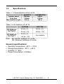
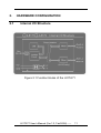
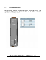
I-8172(H)/71(H) User’s Manual Warranty All products manufactured by ICP DAS are warranted against defective materials for a period of one year from the date of delivery to the original purchaser. Warning ICP DAS assumes no liability for damages consequent to the use of this product. ICP DAS reserves the right to change this manual at any time without notice. The information furnished by ICP DAS is believed to be accurate and reliable. However, no responsibility is assumed by ICP DAS for its use, not for any infringements of patents or other rights of third parties resulting from its use. Copyright Copyright 2004 by ICP DAS. All rights are reserved. Trademark The names used for identification only may be registered trademarks of their respective companies. Web Site: http://www.icpdas.com I-8172/71 User’s Manual (Ver.1.2, Feb/2006) ----- 1 Tables of Contents 1. INTRODUCTION.............................................................3 1.1 FEATURES ..................................................................... 6 1.2 SPECIFICATIONS ............................................................ 8 1.3 ORDERING INFORMATION ............................................... 9 1.3.1Options...................................................................... 9 1.4 PRODUCT CHECK LIST ................................................. 10 2. HARDWARE CONFIGURATION .................................11 2.1 INTERNAL I/O STRUCTURE ........................................... 11 2.2 PIN ASSIGNMENTS ....................................................... 12 3. SOFTWARE FUNCTIONS ...........................................13 3.1 I-8000 CONTROLLERS ................................................. 13 3.2 WINCON-8000 CONTROLLERS ..................................... 15 4. FRNET APPLICATION STRUCTURE .........................16 I-8172/71 User’s Manual (Ver.1.2, Feb/2006) ----- 2 1. INTRODUCTION FRnet is a two-wire serial communication bus and is wired in a similar manner as the RS-485. FRnet devices connect to the communication by using the multi-drop method. Unlike most communication methods based on RS-485, FRnet does not use the traditional question/answer approach. Instead, it uses special chips to actively transmit data with a fixed scan time. Since there is no need of a CPU to process a communication protocol, FRnet can achieve high-speed data transmission in an isochronous manner. The I-8172/72H/71/71H is an isolated FRnet communication module designed for use in WinCon, LinCon and I-8000 controllers. I-8171 module has one FRnet port whereas the I-8172 module has two FRnet ports. Each FRnet port has 8 sender nodes and 8 receiver nodes. That is, the node address setting is defined as SA0~SA7 and RA8~RA15. Each node contains 16-bit data, which can be either a DI or DO type depending on what module you use. Therefore, it can control up to a maximum of 128 (= 16*8) digital output channels and 128 (= 16*8) digital input channels with a total scan time of 2.88ms for 250kbps or 0.72ms for 1Mbps (for the H version). Note: The H version modules can not work together with the normal speed modules. I-8172/71 User’s Manual (Ver.1.2, Feb/2006) ----- 3 I/O data transmission of the FRnet communication is controlled by the FRnet control chip which was developed by ICPDAS. It is designed to provide a deterministic high speed communication for this network. This communication mechanism is dominated by the token stream, which is generated by the network manager (located at SA0 node). It provides a fixed scan-time for I/O synchronization without special communication protocol. Furthermore, special antinoise circuitry has been built into the FRnet control chip to ensure communication reliability. However, the effectiveness of the FRnet depends on and is then ensured when the correct hardware configurations for the sender address (SA) and receiver address (RA) on the host controller and the remote module in the network have been installed properly. In general, the operating principle is structured by the strategy of delivering the 16-bit data from the specified sender address (SAn) to the corresponding receiver address (RAn) via the broadcasting method controlled by the token-stream of the network manger, SA0. Based on this algorithm, there are some general rules that need to be followed: (1) The sender address needs to be unique in order to avoid any communication collisions. (2) Each of FRnet bus needs one and only one network manger defined as SA0. It plays the important role of producing the token-stream in the network. I-8172/71 User’s Manual (Ver.1.2, Feb/2006) ----- 4 (3) The baud rates of the controller and the remote module need to be the same as on the FRnet. (4) The communication method is controlled by delivering the data of the specified sender address (SA) to the corresponding receiver address (RA) in the sequence of token 0 to (N-1) cyclically, as depicted below. (5) Due to the broadcasting algorithm adopted, the receiver address is not required to be unique. Therefore, it is easy to build in data delivery from one node (16-bit data) to a multinode. Figure 1.1 Token stream controlled by network manger, SA0 Each port of I-8172/71 host module contains nodes from SA0~7 and RA8~15. That means each port on I-8172/71 can connect to devices which have node addresses set between RA0~7 and SA8~15. The RA node on device can receive the command data from host module. Therefore, remote FRnet DO modules must have I-8172/71 User’s Manual (Ver.1.2, Feb/2006) ----- 5 RA nodes. In a similar way, the remote FRnet DI modules must have SA nodes. The registers of SA and RA nodes on the host are mapped to a region of host’s memory. Users can easily control the FRnet I/O module through reading and writing the specified memory located on the host computer. Figure 1.2 FRnet application structure 1.1 Features The Token stream is used to activate data transmission from the specified SA node to the corresponding RA nodes. The Network Manager is defined as SA0. Each of FRnet must have SA0 because it issues the Token stream into the network. The Token stream is produced cyclically by hardware at the fixed time interval, see Figure 1.1. Therefore, the FRnet I/O I-8172/71 User’s Manual (Ver.1.2, Feb/2006) ----- 6 system can provide both the isochronous and deterministic functionalities. It can provide data transmission from one node (SA) to remote multiple nodes (RA) at the same time. It implies that the SA address must be unique, but the RA address can be different or the same in the network. The FRnet system can be easily extended by adding new modules to the network. Device Inter-communication: A single device can talk to other devices by setting appropriate SA and RA node configurations. Adopt Memory-mapping technology to control I/O nodes. No software overhead: all data transmissions are performed automatically via the FRnet control chips. Therefore, there is no need for the CPU to process transmission protocols. It only needs simple RS-485 wiring method. OS (operation system) independent. I-8172/71 User’s Manual (Ver.1.2, Feb/2006) ----- 7 1.2 Specifications Table 1.1 Characteristics of the I-8172 I-8172/71 I-8172H/71H Transfer speed Scan time Max transfer length 250Kbps 2.88ms 400 m Table 1.2 I/O Address of I-8172 I-8172/H I/O Address for Port 0 I/O Address for Port 1 1Mbps 0.72ms 100 m I-8171/H SA [0]~[7] , SA [0]~[7] , RA [8]~[15] RA [8]~[15] SA [0]~[7] , RA [8]~[15] Not Available Note: SA: Sender Address of a node, RA: Receiver Address of a node. General specifications: • • • • Operation temperature: -25°C~+75°C Storage temperature: -30°C~+80°C Humidity: 5~95% Power consumption: 2 W(Max) I-8172/71 User’s Manual (Ver.1.2, Feb/2006) ----- 8 1.3 Ordering information • I-8172 : • I-8171 : • I-8172H: • I-8171H: 250Kbps (2 Ports: SA 0~7, RA 8~15) 250Kbps (1 Port : SA 0~7, RA 8~15) 1Mbps (2 Ports: SA 0~7, RA 8~15) 1Mbps (1 Port : SA 0~7, RA 8~15) Note: the high-speed version can be selected by an internal jumper. 1.3.1 Options z FR-2057 series: 16-channel Isolated Digital Output Distributed I/O Module. z FR-2053 series: 16-channel Isolated Digital Input Distributed I/O Module. z DN-20/1m: Terminal board with two 20-pin flat cables (CA2010). z FR-8R/16R/32R: 8/16/32-channel relay output terminal board. z FR-8P/16P/32P: 8/16/32-channel photo-isolated input terminal board. z FR-8A/16A/32A: 8/16/32-channel Open drain output terminal board. z Other FRnet modules: Please refer to the web site of ICP DAS. I-8172/71 User’s Manual (Ver.1.2, Feb/2006) ----- 9 1.4 Product Check list In addition to this manual, this package should include the following items: • One I-8172/71 module • One copy of the release notes Before continuing, please read the release notes first. They contain the following important information. 1. The location of the software driver and utility 2. FAQ’s Attention! If any of these items are missing or damaged, contact the dealer from whom you purchased the product. Save all shipping materials and the carton in case you need to ship or store the product in the future. I-8172/71 User’s Manual (Ver.1.2, Feb/2006) ----- 10 2. 2.1 HARDWARE CONFIGURATION Internal I/O Structure Figure 2.1 Function blocks of the I-8172/71 I-8172/71 User’s Manual (Ver.1.2, Feb/2006) ----- 11 2.2 Pin Assignments I-8172 module has two FRnet ports (similar to RS-485 ports). The definitions of the pins on the connectors for the FRnet ports are shown in the following Table. I-8172/71 User’s Manual (Ver.1.2, Feb/2006) ----- 12 3. 3.1 SOFTWARE FUNCTIONS I-8000 Controllers BC and TC users can use i8172_Init(), i8172_Write_DO_Group() and i8172_Read_DI_Group() functions to control the FRnet DI/O. The necessary step and function description are as follows. 1. Add “#Include “i8172.h” to the header of project. 2. Function Lists: int i8172_Init (int iSlot); /****************************************************** Use this function to initialize the assigned module. iSlot: 0~7 return: 0: OK; -1: Error *******************************************************/ void i8172_Write_DO_Group (int iSlot, int iPort, int iGroup, unsigned int iData); /********************************************************** Use this function to write value to DO module. iSlot: 0~7 iPort: 0 or 1 iGroup: 0~7 iData: Every group has 16 DO channels. Each bit in iData sets a DO value. ***********************************************************/ void i8172_Write_DO_Bit(int iSlot, int iPort, int iGroup, int iBit, int iStatus); /**************************************************************** Use this function to set a DO of the assigned module. iSlot: 0~7 iPort: 0 or 1 iGroup: 0~7 I-8172/71 User’s Manual (Ver.1.2, Feb/2006) ----- 13 iBit: 1~16 iStatus: 0: OFF; 1: ON ****************************************************************/ unsigned int i8172_Read_DI_Group (int iSlot, int iPort, int iGroup); /************************************************************** Use this function to read the assigned group’s DI value. iSlot: 0~7 iPort: 0 or 1 iGroup: 0~7 Every group has 16 channels. **************************************************************/ unsigned int i8172_Read_DI_Bit (int iSlot, int iPort, int iGroup, int iBit); /************************************************************* Use this function to read single channel from DI module. iSlot: 0~7 iPort: 0 or 1 iGroup: 0~7 iBit: 1 ~ 16 ************************************************************/ int i8172_GetLibVersion ( ); /********************************************************* Read the version of the library file. *********************************************************/ void i8172_GetLibDate (unsigned char *LibDate); /******************************************************** Read the released date of the library file. *********************************************************/ I-8172/71 User’s Manual (Ver.1.2, Feb/2006) ----- 14 3.2 WinCon-8000 controllers For eVC++ 4.0 user only use FRNET_SA() and FRNET_RA() function can control the FRNET DI/O. The necessary step and function description are as follows. 1. 2. Added “#Include “WinConSDK.h” to the header of project. Use FRNET_SA() for DO output; and use FRNET_RA() for DI input. FRNET_SA (BYTE Slot, BYTE Port, BYTE wSA, WORD Data); For example: FRNET_SA(1, 0, 0, 0x3); // Write 0x3 to SA 0 of FRnet port 0 on the host module located // at Slot 1. This value will be sent to remote FRnet RA module // (DO) and set the bit 0 and 1 to be active (On). FRNET_RA (BYTE Slot, BYTE Port, BYTE wRA); For example: WORD Read_BK = FRNET_RA (1, 0, 8); // Get the DI status from RA 8 of FRnet port 0 on the host // module located at Slot 1. The value is saved to the // Read_BK variable. NOTE: For more detailed information, please refer to the manual of WinCon-8000 ( WinCon EVC++ SDK). I-8172/71 User’s Manual (Ver.1.2, Feb/2006) ----- 15 4. FRnet APPLICATION STRUCTURE Figure 4.1 Note: 1. Refer to the “FRnet distributed I/O module manual” for details regarding the settings of the DSW (dipswitch). 2. The high-speed FRnet cards and modules can only work together with high-speed remote modules. Similarly, the normal speed cards can only work with normal speed remote modules. 3. The cabling method is similar to that used with the RS-485 networks. For long distance usage, a shielded twisted pair cable is required. I-8172/71 User’s Manual (Ver.1.2, Feb/2006) ----- 16