1
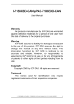
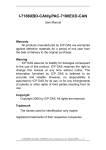
I-87120
User Manual
Warranty
All products manufactured by IPC DAS are warranted
against defective materials for a period of one year from
the date of delivery to the original purchaser.
Warning
ICP DAS assume no liability for damages consequent
to the use of this product. ICP DAS reserves the right to
change this manual at any time without notice. The
information furnished by ICP DAS is believed to be
accurate and reliable. However, no responsibility is
assumed by ICP DAS for its use, nor for any infringements
of patents or other rights of third parties resulting from its
use.
Copyright
Copyright 2005 by ICP DAS. All rights are reserved.
Trademark
The names used for identification only maybe registered
trademarks of their respective companies.
I-87120 user manual (ver. 2.30, Jul/23/2008) ------1
Tables of Content
1
2
3
4
5
Introduction.............................................................................................4
1.1 Overview.........................................................................................4
1.2 Specifications ................................................................................5
1.3 Features..........................................................................................5
Hardware Specification ..........................................................................6
2.1 Hardware Structure........................................................................6
2.2 Wire Connection ............................................................................7
2.3 Power LED....................................................................................10
2.4 Tx/Rx LED.....................................................................................10
2.5 ERR LED .......................................................................................10
I-87120 Host Function Library ............................................................. 11
3.1 Function List ................................................................................ 11
3.2 Programmable Flow Chart ..........................................................12
3.3 I87KCANConfig ............................................................................14
3.4 GetI87KCANConfig ......................................................................15
3.5 SetCANBaud ................................................................................16
3.6 GetCANBaud ................................................................................17
3.7 SetCANMask ................................................................................18
3.8 GetCANMask ................................................................................20
3.9 ClearStatus ...................................................................................21
3.10 GetStatus ......................................................................................22
3.11 ResetI87KCAN..............................................................................23
3.12 I87KCANInit ..................................................................................24
3.13 GetCANMsg..................................................................................26
3.14 SendCANMsg ...............................................................................27
3.15 Function Return Error Code .......................................................28
Demo Programs ....................................................................................29
4.1 TC++1.01 Demo For I-8000 Series MCU .....................................31
4.2 EVC++ Demo For WinCon Series MCU ......................................40
4.3 EVC++ Demo For WinPAC Series MCU......................................48
4.4 GCC Demo For LinCon Series MCU ...........................................55
User-defined Flexibility Firmware .......................................................60
5.1 UserIrqFunc..................................................................................61
5.2 UserInitFunc.................................................................................62
5.3 UserDefCmdFunc ........................................................................63
5.4 UserDefBinaryFunc .....................................................................64
I-87120 user manual (ver. 2.30, Jul/23/2008) ------2
5.5
5.6
6
7
UserLoopFunc .............................................................................65
Others support functions for I-87120 firmware .........................66
5.6.1
I87KCANConfig................................................................66
5.6.2
CAN_Reset.......................................................................67
5.6.3
SetCANBaud ....................................................................68
5.6.4
GetCANBaud....................................................................69
5.6.5
SetCANMask ....................................................................70
5.6.6
GetCANMask....................................................................72
5.6.7
SendCANMsg...................................................................73
5.6.8
GetCANMsg .....................................................................74
5.6.9
GetCANStatus..................................................................75
5.6.10 RxMsgCount ....................................................................76
5.6.11 ClearTxSoftBuffer............................................................77
5.6.12 ClearRxSoftBuffer ...........................................................78
TC++1.01 Firmware Demo For I-87120 ................................................79
Troubleshooting....................................................................................88
I-87120 user manual (ver. 2.30, Jul/23/2008) ------3
1 Introduction
1.1 Overview
CAN (Controller Area Network) is a serial bus control protocol especially
suited to structure intelligent industry devices networks and build smart automatic
control systems. It is popularly applied in the industrial automation, building
automation, vehicle, marine, and embedded control network. In order to expand
the CAN functions of ICPDAS products, I-87120 module is developed for this
purpose. It is a kind of slot module, and need to be plugged into a host unit, such
as I-8000 series, WinCon-8000 series, LinCon-8000 series, and WinPAC-8000
series PACs (Programmable Automation Controller). I-87120 gives a way to
connect to these ICPDAS host units with CAN network. Owing to the features of
PACs, these host units can be arranged to be a CAN converter, CAN slave device
and CAN master device in a CAN network. The following figure shows the
application architecture for I-87120 modules.
I-87120 user manual (ver. 2.30, Jul/23/2008) ------4
1.2 Specifications
z
z
z
z
z
CPU:80186, 80MHz
Philip SJA1000 CAN controller with 16MHz clock
Philip 82C250 CAN transceiver
Power LED, Tx/Rx LED, Error LED
120Ω terminal resister selected by jumper
z
z
z
z
z
CAN bus interface: ISO 11898-2, 5-pin screw terminal with on-board
optical isolator protection.
2500 Vrms isolation on CAN side
Power Consumption: 2W
Operating Temperature:-25°C to +75°C
Storage Temperature:-30°C to +85°C
z
Humidity:5%~95%
1.3 Features
Common Features:
z One CAN port expansion for I-8000 series, WinCon-8000,
LinCon-8000, and WinPAC-8000 PACs.
z 4096 records CAN message receive-buffer size.
z 4096 records buffer size for the command from I-8000/WinCon-8000
/LinCon-8000/WinPAC-8000 to I-87120.
z Provide C/C++ function libraries to send and receive CAN messages.
z Demos and utility are provided.
z 3 indication LEDs (Rx, Tx and Err LEDs)
CAN Port Features:
z Support user-defined baud
z 2500 Vrms isolation
z Baud : 5Kbps, 10Kbps, 20Kbps, 25Kbps, 50Kbps, 100Kbps, 125Kbps,
200Kbps, 250Kbps, 500Kbps, 800Kbps, 1Mbps.
I-87120 user manual (ver. 2.30, Jul/23/2008) ------5
2 Hardware Specification
2.1 Hardware Structure
Tx/Rx LED
Err LED
Power LED
CAN Port
I-87120 user manual (ver. 2.30, Jul/23/2008) ------6
2.2 Wire Connection
In order to minimize the reflection effects on the CAN bus line, the CAN
bus line has to be terminated at both ends by two terminal resistances as in the
following figure. According to the ISO 11898-2 spec, each terminal resistance
is 120Ω (or between 108Ω~132Ω). The length related resistance should have
70 mΩ/m. Users should check the resistances of the CAN bus, before they
install a new CAN network.
Device 1
Device 2
...
Device N
120Ω
120Ω
CAN_H
CAN_L
Moreover, to minimize the voltage drop over long distances, the terminal
resistance should be higher than the value defined in the ISO 11898-2. The
following table can be used as a good reference.
Bus Cable Parameters
Terminal
Resistance
(Ω)
Bus Length
(meter)
Length Related
Resistance
(mΩ/m)
0~40
70
0.25(23AWG)~
0.34mm2(22AWG)
124 (0.1%)
40~300
< 60
0.34(22AWG)~
0.6mm2(20AWG)
127 (0.1%)
300~600
< 40
0.5~0.6mm2
(20AWG)
150~300
600~1K
< 20
0.75~0.8mm2
(18AWG)
150~300
Cross Section
(Type)
I-87120 user manual (ver. 2.30, Jul/23/2008) ------7
In I-87120, the 120Ω terminal resistance is supplied. The JP1 of I-87120 is
for the terminal resistance and the JP2 is RS232 COM port for download
firmware of I-87120. Users can use special cable to download the firmware
into I-87120. This cable is named CA0904 and shown as follows:
The JP3 is the initial jumper of I-87120. If users want to stop the firmware,
uses need to turn off the I-87120 and connect the JP3 jumper. Then turn on the
I-87120. The locations of all jumpers are shown in the following figure.
Hardware Profile
I-87120 user manual (ver. 2.30, Jul/23/2008) ------8
The following connection statuses are presented for the condition if the
terminal resister is enabled or disabled.
JP1 Jumper selection
JP3 Jumper selection
The pin assignment of I-87120 CAN bus connector is shown below.
Pin No.
Signal
Description
1
N/A
No use
2
CAN_H
CAN_H bus line (dominant high)
3
CAN_SHLD
Optional CAN Shield
4
CAN_L
CAN_L bus line (dominant low)
5
N/A
No use
I-87120 user manual (ver. 2.30, Jul/23/2008) ------9
2.3 Power LED
I-87120 slot module needs 2W power consumption. If the electric power is
supplied normally, the Power LED will be turn on always. If any other situation,
please check the power supply or contact to your distributor.
2.4 Tx/Rx LED
Each I-87120 slot module provides Tx/Rx LED to check the CAN
messages transmission and reception situation. If the I-87120 is transmitting or
receiving a CAN message, the Tx/Rx LED will blink. If I-87120’s loading is
heavy, the Tx/Rx LED will always turn on.
2.5 ERR LED
The ERR LED indicates the error status of the CAN physical layer and
indicates the errors due to missing CAN messages. When the I-87120 ERR
LED is turned on, users can use the function GetStatus( ) to obtain the error
status and know what is happen. If the ERR LED is turned on due to the
software buffer overflow, the buffer error flag can be clear by using the function
ClearStatus(). For more detail about these functions, please refer to the
section 3.
I-87120 user manual (ver. 2.30, Jul/23/2008) ------10
3 I-87120 Host Function Library
3.1 Function List
In order to use the I-87120 more easily, the I-87120 function library used in
host side is provided. There are several function libraries for different compiler,
such as BC/TC/MSC (I-8000 series), EVC (WinCon-8000 and WinPAC-8000),
and GCC (LinCon-8000). Users can use these functions to control the I-87120
by the functions. The following table shows the all functions provided by the
I-87120 library.
Function Name
Description
Configure the I-87120
I87KCANConfig
GetI87KCANConfig
Obtain the I-87120 configuration
SetCANBaud
Set the I-87120 CAN baud rate
GetCANBaud
Obtain the CAN baud rate stored in the I-87120
SetCANMask
Set the I-87120 CAN message filter
GetCANMask
Obtain the CAN message filter stored in the I-87120
ClearStatus
GetStatus
ResetI87KCAN
Clear the I-87120 software buffer overflow status
Get the I-87120 software buffer or CAN status
Reset the I-87120 module
I87KCANInit
Initiate the I-87120 module. Users need to set the
proper CAN and I-87120 configuration to the I-87120
GetCANMsg
Obtain the CAN message received by the I-87120
SendCANMsg
Send a CAN message to the CAN network
I-87120 user manual (ver. 2.30, Jul/23/2008) ------11
3.2 Programmable Flow Chart
If users want to develop the program with I-87120 module, the following
procedure may be a good reference.
Start
Note 1
InstallCom0( )
Note 2
ChangeToSlot( )
I87KCANInit( )
Send CAN
message?
Yes
No
GetCANMsg( )
Yes
SendCANMsg( )
Exit Program?
No
Note 3
RestoreCom0( )
End
I-87120 user manual (ver. 2.30, Jul/23/2008) ------12
Note1: If the host side is I-8000 series main control unit, the function
InstallCom0( ) is used here. If the host side is WinCon-8000,
LinCon-8000 or WinPAC-8000, the function Open_Com( ) is used.
Note2: If the host side is I-8000 series main control unit, the function
ChangeToSlot( ) is used here. If the host side is WinCon-8000 or
WinPAC-8000, the function ChangeSlotTo87K( ) is used. In
LinCon-8000 host side, the function Open_Slot( ) is needed.
Note3: If the host side is I-8000 series main control unit, the function
RestoreCom0( ) is used here. If the host side is WinCon-8000,
LinCon-8000 or WinPAC-8000, the function Close_Com( ) is used.
Take the I-8000 series main control unit for example. Before users use the
I-87120 functions, the function InstallCom0( ) and ChangeToSlot( ) must be
used first. The function ChangeToSlot( ) is used to define which I-87K series
slot module users want to operate now. For example, if users want to use the
I-87120 module plugged in the slot 0, the code is shown as follows.
ChangeToSlot(0);
Afterwards, users need to initiate the I-87120 module by using the function
I87KCANInit( ). Then, users can use I87KCAN.lib arbitrarily. Before users
close their application program, don’t forget to use the function RestoreCom0( )
to recover the COM port setting.
I-87120 user manual (ver. 2.30, Jul/23/2008) ------13
3.3 I87KCANConfig
z
Description:
Use this function to set the I-87120 configuration.
z
Syntax:
int I87KCANConfig(unsigned char Ack, unsigned char BufferSize)
z
Parameters:
Ack: This parameter is used for setting the host command acknowledge
status. If this parameter is set to 1, the I-87120 would not send the
acknowledge message or error message after receiving a host
command. Therefore, users function would not hang because of
waiting the acknowledge message or error message. In some
application case, it may reduce the communication time.
BufferSize: Setting this parameter to 1 will disable the software buffer
functionality. This means that the I-87120 would have no
buffer to store the CAN message. In this case, the I-87120
would recover the previous CAN data when the new CAN
message is received. Therefore, users would lose the CAN
data if they don’t read back the data and the new one is
coming. The advantage is that users can always get the
newest CAN message.
z
Return:
CAN87K_OK
CAN87K_PARATERS_ERROR
CAN87K_TIMEOUT
I-87120 user manual (ver. 2.30, Jul/23/2008) ------14
3.4 GetI87KCANConfig
z
Description:
Use this function to get the Ack and BufferSize parameters stored in the
I-87120.
z
Syntax:
int GetI87KCANConfig (unsigned char *Ack, unsigned char *BufferSize)
z
Parameters:
*Ack: The pointer for obtaining the Ack parameter stored in the I-87120.
For more information about the Ack parameter, please refer to the
section 3.3.
*BufferSize: The pointer for obtaining the BufferSize parameter stored in
the I-87120. About the information of BufferSize parameter,
please refer to the section 3.3.
z
Return:
CAN87K_OK
CAN87K_PARATERS_ERROR
CAN87K_TIMEOUT
I-87120 user manual (ver. 2.30, Jul/23/2008) ------15
3.5 SetCANBaud
z
Description:
Call this function to set the I-87120 CAN baud rate.
z
Syntax:
int SetCANBaud(unsigned long Baud, unsigned char BT0,
unsigned char BT1)
z
Parameters:
Baud: I-87120 slot module has several predefine CAN baud rates. Use
this parameter to decide what kind of baud rate users want to use.
Here, twelve kinds of baud rates are supported. They are 5K, 10K,
20K, 25K, 50K, 100K, 125K, 200K, 250K, 500K, 800K and 1000K
bps. For example, set the Baud value to 250000L to set I-87120
CAN baud to 250K bps. The letter L means that the value 250000
is the long integer format. If users can’t find out the proper CAN
baud rate for their application, the user-defined baud rate
functionality may be needed. The parameters BT0 and BT1 are
specially used for setting the user-defined baud rate. When users
call the function SetCANBaud() without using the Baud value listed
above, the Baud value is useless, and the parameters BT0 and
BT1 would be applied for user-defined CAN baud rate.
BT0, BT1: These parameters are useful for user-defined CAN baud rate.
The values of BT0 and BT1 need to be calculated according to
the SJA1000 CAN controller datasheet. For more information
about how to calculate the CAN baud, please refer to the
following web site.
http://www.semiconductors.philips.com
z
Return:
CAN87K_OK
CAN87K_CAN_REG_ERROR
CAN87K_PARATERS_ERROR
CAN87K_TIMEOUT
I-87120 user manual (ver. 2.30, Jul/23/2008) ------16
3.6 GetCANBaud
z
Description:
Call this function to get the CAN baud used by the I-87120.
z
Syntax:
int GetCANBaud(unsigned long *Baud, unsigned char *BT0,
unsigned char *BT1)
z
Parameters:
* Baud: The pointer for obtaining the CAN baud rate. If users use the
predefine baud rate, the function GetCANBaud() would return
the CAN baud rate used by I-87120. If the return value of Baud
is 0, it means that the I-87120 use user-defined CAN baud. In
this case, the CAN baud rate would be indicated by using the
parameters *BT0 and *BT1.
* BT0, * BT1: The pointer for obtaining the user-defined CAN baud used
by I-87120.
z
Return:
CAN87K_OK
CAN87K_PARATERS_ERROR
CAN87K_TIMEOUT
I-87120 user manual (ver. 2.30, Jul/23/2008) ------17
3.7 SetCANMask
z
Description:
Use this function to set the I-87120 parameters.
z
Syntax:
int SetCANMask(unsigned long AccCode, unsigned long AccMask)
z
Parameters:
AccCode, AccMask: The AccCode is used for deciding what kind of ID the
CAN controller would accept. The AccMask is used
for deciding which bit of ID would need to check with
AccCode. If the bit of AccMask is set to 0, it means
that the bit in the same position of ID needs to be
checked, and that ID bit value needs to match the bit
of AccCode in the same position. The following table
shows each situation of AccCode and AccMask.
For 11-bit ID Message:
AccCode and AccMask
Bit Position
Filter Target
high byte of the high word
bit7~bit0
bit10 ~ bit3 of ID
low byte of the high word
bit7~bit5
bit2 ~ bit0 of ID
low byte of the high word
bit4
RTR
low byte of the high word
bit3~bit0
no use
high byte of the low word
bit7~bit0
bit7 ~ bit0 of 1st byte data
low byte of the low word
bit7~bit0
bit7 ~ bit0 of 2nd byte data
I-87120 user manual (ver. 2.30, Jul/23/2008) ------18
For 29-bit ID Message:
AccCode and AccMask
Bit Position
Filter Target
high byte of the high word
bit7~bit0
bit28~ bit21 of ID
low byte of the high word
bit7~bit0
bit20 ~ bit13 of ID
high byte of the low word
bit7~bit0
bit12 ~ bit5 of ID
low byte of the low word
bit7~bit3
bit4 ~ bit0 of ID
low byte of the low word
bit2
RTR
low byte of the low word
bit1~bit0
no use
For example (In 29 bit ID message):
AccCode :
00h
00h
00h
A0h
AccMask :
FFh
FFh
FFh
1Fh
ID bit
ID Value
bit28~bit21 bit20~bit13 bit12~bit5
:
xxxx xxxx
xxxx xxxx
xxxx xxxx
bit4~bit0
101x x
will be accepted
(Note: The mark “x” means don’t care. And the mark “h” behind the value means hex format.)
z
Return:
CAN87K_OK
CAN87K_CAN_REG_ERROR
CAN87K_PARATERS_ERROR
CAN87K_TIMEOUT
I-87120 user manual (ver. 2.30, Jul/23/2008) ------19
3.8 GetCANMask
z
Description:
Call this function to get the CAN message filter situation.
z
Syntax:
int GetCANMask(unsigned long *AccCode, unsigned long *AccMask)
z
Parameters:
*AccCode, *AccMask: These pointer for obtaining the AccCode and
AccMask used by the I-87120. For more
information about these two parameters, please
refer to the section 3.7.
z
Return:
CAN87K_OK
CAN87K_PARATERS_ERROR
CAN87K_TIMEOUT
I-87120 user manual (ver. 2.30, Jul/23/2008) ------20
3.9 ClearStatus
z
Description:
This function is used for cleaning the CAN and host command software
buffer overflow error flag. When the CAN message software buffer or host
command software buffer is full, the CAN or host command buffer
overflow error flag will be set to 1. In this case, users need to use this
function to clear the error flag to acknowledge the error information.
z
Syntax:
int ClearStatus(void)
z
Parameters:
None
z
Return:
CAN87K_OK
CAN87K_PARATERS_ERROR
CAN87K_TIMEOUT
I-87120 user manual (ver. 2.30, Jul/23/2008) ------21
3.10 GetStatus
z
Description:
Read the I-87120 CAN controller status and software buffer error flag
message
z
Syntax:
int GetStatus(unsigned char *CANReg, unsigned char *OverflowFlag)
z
Parameters:
* CANReg: The pointer for obtain the I-87120 current CAN controller
status. For the information about the CANReg value meaning,
please refer to the following table.
Bit NO.
Description
7 (MSB)
Bus status. 1 for bus off, 0 for bus on.
6
Error status. 1 for at least one error, 0 for OK.
5
Transmit status. 1 for transmitting, 0 for idles.
4
Receive status. 1 for receiving, 0 for idles.
3
Transmit complete status. 1 for complete, 0 for incomplete.
2
Transmit buffer status. 1 for released, 0 for locked
1
Data overrun status. 1 for reception buffer overrun, 0 for OK.
0 (LSB)
Receive buffer status. 1 for at least one message stored in the
reception buffer, 0 for empty.
* OverflowFlag: CAN and host command buffer overflow flag information.
For the information about the OverflowFlag value
meaning, please refer to the following table.
Bit NO.
Others
1
0 (LSB)
z
Description
Reserved
1 for host command buffer overflow. 0 for normal.
1 for CAN receive message buffer overflow. 0 for normal.
Return:
CAN87K_OK
CAN87K_PARATERS_ERROR
CAN87K_TIMEOUT
I-87120 user manual (ver. 2.30, Jul/23/2008) ------22
3.11 ResetI87KCAN
z
Description:
This function is used to reset the I-87120 module. Calling this function will
clear not only the CAN controller register error flag but also CAN and host
command software buffer error flags. When the CAN controller is bus-off,
it may be called. After applying this function, the I-87120 configuration,
CAN baud, and CAN message filter stored in the I-87120 EEPROM
would be applied when the I-87120 reboots.
z
Syntax:
int ResetI87KCAN(void)
z
Parameters:
None
z
Return:
CAN87K_OK
CAN87K_PARATERS_ERROR
CAN87K_TIMEOUT
I-87120 user manual (ver. 2.30, Jul/23/2008) ------23
3.12 I87KCANInit
z
Description:
When users want to use I-87120 module, this function must be called first.
Afterwards, The CAN baud, CAN message filter and I-87120
configurations would be applied to the I-87120.
z
Syntax:
int I87KCANInit(unsigned long CANBaud, unsigned char BT0,
unsigned char BT1, unsigned long CAN_AccCode,
unsigned long CAN_Mask, unsigned char Ack,
unsigned char BufferSize)
z
Parameters:
CANBaud: Set this parameter to configure the I-87120 CAN baud rate.
For example, use the value 250000L to set the CAN baud rate
to 250K bps. The letter L means long integer format for the
value 250000.
BT0, BT1: If the CANBaud parameter is set to 0, the BT0 and BT1 will be
used for configuring the I-87120 baud rate. This case will be
applied if users want to define a special CAN baud rate. For
more information about how to set the BT0 and BT1 value,
please refer to the SJA1000 CAN controller datasheet. Users
can find it on the following website.
http://www.semiconductors.philips.com
CAN_AccCode, CAN_Mask: Set this parameter for CAN message filter.
The using method is the same with the AccCode and AccMask
parameters of function SetCANMask. Therefore, please refer
to the section 3.7 to know about the CAN message filter
configuration.
I-87120 user manual (ver. 2.30, Jul/23/2008) ------24
Ack: This parameter is used for setting the host command acknowledge
status. If this parameter is set to 1, the I-87120 would not send the
acknowledge message after receiving a host command. Therefore,
users function would not hang because of waiting the acknowledge
message. In some application case, it may reduce the
communication time.
BufferSize: Setting this parameter to 1 would disable the CAN software
buffer functionality. This means that the I-87120 would have no
buffer to store the CAN message. In this case, the I-87120
would recover the previous CAN data when the new CAN
message is received. Therefore, users would lose the CAN
data if they don’t read back the data and the new one is
coming. The advantage is that users can always get the
newest CAN message.
z
Return:
CAN87K_OK
CAN87K_PARATERS_ERROR
CAN87K_CAN_REG_ERROR
CAN87K_INIT_ERROR
CAN87K_TIMEOUT
I-87120 user manual (ver. 2.30, Jul/23/2008) ------25
3.13 GetCANMsg
z
Description:
If the CAN message is received by I-87120 module, use this function to
read back the CAN messages.
z
Syntax:
int GetCANMsg(unsigned char *Mode, unsigned long *MsgID,
unsigned char *RTR, unsigned char *DataLen,
unsigned char *Data)
z
Parameters:
*Mode: The parameter *Mode is used to point out the CAN message
specification. If the CAN message is CAN 2.0A specification,
the Mode value is given to 0. If it is CAN 2.0B specification, the
value is 1.
*MsgID: The parameter *ID is used to point to the attribution ID of a CAN
message. If the I-87120 receive a CAN message with
specification 2.0A, the ID value range is from 0x0 to 0x3FF. If
CAN message is 2.0B, the ID value range is from 0x0 to
0x1FFFFFFF.
*RTR: This parameter is used to get the RTR status of a CAN message.
The RTR value is 0 if the CAN message is normal CAN frame. If it
is 1, the CAN message is remote-transmit-request CAN frame.
*DataLen: The *DataLen is point to the value indicates how many data
stored in the array Data[ ] (see the parameter *Data below).
The maximum value is 8.
*Data: This parameter needs a pointer to point an array which is used to
stored the CAN message data. Because the maximum data
numbers of one CAN message is 8 bytes, it is recommend that the
array Data[ ] size is 8 bytes.
Return:
CAN87K_OK
CAN87K_PARATERS_ERROR
CAN87K_FIFO_EMPTY
CAN87K_TIMEOUT
I-87120 user manual (ver. 2.30, Jul/23/2008) ------26
3.14 SendCANMsg
z
Description:
If users want to send a CAN message by I-87120 module, use this
function to transmit the CAN message.
z
Syntax:
int SendCANMsg(unsigned char Mode, unsigned long MsgID,
unsigned char RTR, unsigned char DataLen ,
unsigned char* Data)
z
Parameters:
Mode: The parameter Mode is used set the transmitting CAN message
specification. If the CAN message is CAN 2.0A specification, the
Mode value is 0. If it is CAN 2.0B specification, the value is 1.
MsgID: The parameter ID is used to set the attribution ID of a CAN
message. If the transmitting CAN message is for specification
2.0A, the ID value range is from 0x0 to 0x3FF. If the CAN
message is for specification 2.0B, the ID value range is from 0x0
to 0x1FFFFFFF.
RTR: Use this parameter to set the RTR status of the transmitting CAN
message. The RTR value is 0 if the CAN message is normal CAN
frame. If it is 1, the CAN message is remote-transmit-request CAN
frame.
DataLen: The DataLen indicates how many data will be transmitted in the
array Data[ ] (see the parameter *Data below). The maximum
value of DataLen is 8.
*Data: This parameter needs a pointer to point an array. This array
include the date which would be transmitted to the CAN network.
Because the maximum data numbers of a CAN frame is 8 bytes,
more than 8 bytes data in the array Data[ ] will be ignored.
z
Return:
CAN87K_OK
CAN87K_PARATERS_ERROR
CAN87K_FIFO_FULL
CAN87K_TIMEOUT
I-87120 user manual (ver. 2.30, Jul/23/2008) ------27
3.15 Function Return Error Code
The following table displays the function return error codes which may
return from the functions provided by I87KCAN library.
Error code
value
Description
CAN87K_OK
0
OK
CAN87K_TIMEOUT
21
No message response before
time is up.
CAN87K_FIFO_EMPTY
22
The software buffer which stores
the CAN messages is empty.
CAN87K_FIFO_FULL
23
The software buffer which stores
the host commands is full.
CAN87K_INIT_ERROR
24
Initiate I-87120 failure
CAN87K_PARATERS_ERROR
25
Host command error
CAN87K_CAN_REG_ERROR
26
Set CAN controller register
failure
I-87120 user manual (ver. 2.30, Jul/23/2008) ------28
4 Demo Programs
The following architecture is the demos and libraries positions in the path
CAN/SlotModule/I_87120 in CAN CD.
|--\manual
|--\FirmwareLib
|--\DefFirm
|--\Library
|--\Demos
|--\I-8000
|--\87CANLib
|--\MCU_Lib
|--\Download_Tool
|--\MCU_OS
|--\Demos
|--\BCPP31
|--\TCPP101
|--\MSC6
|--\WinCE
|--\EVC
|--\WinCon
|--\87CANLib
|--\SendMsg
|--\RecMsg
|--\Demo_ALL
|--\WinPAC
|--\87CANLib
|--\SendMsg
|--\RecMsg
|--\Demo_ALL
|--\Linux
|--\GCC
|--\87CANLib
|--\SendMsg
|--\RecMsg
Æ Users manual
Æ Library and demo for I-87120
Æ I-87120 default firmware
Æ I-87120 library for user-defined firmware
Æ All the demo of the user-defined firmware
Æ demos and library for I-8000 series MCU
Æ I-87120 library for I-8000 series MCU
Æ I-8000 series MCU library
Æ I-8000 series MCU program download tool
Æ I-8000 series MCU OS image
Æ I-87120 demo programs
Æ demos for Borland C++ 3.1
Æ demos for Turbo C++ 1.01
Æ demos for MSC 6.0
Æ demos and library for WinCon series MCU
Æ I-87120 demos for EVC++ 4.0
Æ demos and library for WinCon series MCU
Æ I-87120 library for WinCon series MCU
Æ I-87120 send CAN messages demo
Æ I-87120 receive CAN messages demo
Æ WinCon CAN Utility program source code
Æ demos and library for WinPAC series MCU
Æ I-87120 library for WinPAC series MCU
Æ I-87120 send CAN messages demo
Æ I-87120 receive CAN messages demo
Æ WinPAC CAN Utility program source code
Æ demos and library for LinCon series MCU
Æ I-87120 demos for GCC
Æ I-87120 library for LinCon series MCU
Æ I-87120 send CAN messages demo
Æ I-87120 receive CAN messages demo
I-87120 user manual (ver. 2.30, Jul/23/2008) ------29
Here, we provide the demo programs about how to use the I-87120 library
in I-8000 series MCU, WinCon series MCU, LinCon series MCU, and WinPAC
series MCU. For I-8000 series MCU, the demo program for BC++3.1 (Borland
C++ version 3.1), TC++1.01 (Turbo C++ version 1.01), and MSC6 (Microsoft
C++ 6.0) compliers is given. In WinCon and WinPAC series MCU, the demos
for EVC++ 4.0 (Embedded Visual C++) is provided. In LinCon series MCU, we
provide the GCC demo program. The step-by-step demo procedure for
TC++1.01, EVC++, and GCC will be given in the following section.
When users want to compile the demo program for I-8000 series MCU,
please copy the demo folder into a new folder named with max 8 letters
because the compiler is 16-bit compiler and may have a trouble due to the long
file name. All of these demos may give a good model to show how to build an
execution file with I87KCAN library. Take a note that if users don’t have any
program development tools, the TC++1.01 and EVC++ can be free download
form the Borland and Microsoft web site. They are shown below.
Download TC++ 1.01:
http://community.borland.com/museum
Download EVC++ 4.0:
http://www.microsoft.com/downloads/details.aspx?familyid=1DACDB3D-50D1
-41B2-A107-FA75AE960856&displaylang=en
The LinCon program development tool, GCC, can also free download on the
ICPDAS web site:
Download GCC:
http://ftp.icpdas.com.tw/pub/cd/linconcd/napdos/linux/sdk/
I-87120 user manual (ver. 2.30, Jul/23/2008) ------30
4.1 TC++1.01 Demo For I-8000 Series MCU
Here, it is considered that how to build an execution file with C87H103L.lib
and how to run this program on the I-8000 series MCU. In this demo, the
I-8811 MCU with 40 MHz and TC++1.01 compiler will be used. The procedure
for all the other I-8000 MCUs will be the same with this demo.
Step1: Create a folder named “MyDemo” in the C disk.
Step2: Copy users’s .c file, and I-87120 library files (C87H103L.lib and
I87KCAN.h) into MyDemo folder. Users can find them with version 1.03
in the path CAN\SlotModule\I_87120\I_8000\87CANLib\ver_103 in
CAN product CD.
I-87120 user manual (ver. 2.30, Jul/23/2008) ------31
Step3: Copy I-8000 series MCU library files (8000.h and 8000E.lib) into
MyDemo folder, too. Users can find them in the path
CAN\SlotModule\I_87120\I_8000\MCU_Lib in CAN product CD.
Step4: Open your .c file with Notepad. Confirm the 8000.h and I87KCAN.h
path in the “#include” syntax. They are shown below.
#include “8000.h”
#include “I87KCAN.h”
I-87120 user manual (ver. 2.30, Jul/23/2008) ------32
Step5: Run the TC++1.01 development environment. Click the “Options\Full
menus” to expand the all functions list in the menus.
Step6: Click the “Project\Open project…” to create a new project. Input the
project name “MyDemo.PRJ”, and click OK button to continue.
I-87120 user manual (ver. 2.30, Jul/23/2008) ------33
Step7: Click Add function on the bottom of TC++1.01 window. Search all .c file
by setting c:\MyDemo\*.c in the Name field of popup window. Then, use
the Add button to add the users’ .c file in to MyDemo project. Then,
change
the
search
command
from
“c:\MyDemo\*.c”
to
“c:\MyDemo\*.lib” in the Name field. Add the library files C87H103L.lib
and 8000E.lib into MyDemo project by the same way.
Step8: After finishing the Step7, the TC++1.01 window will look like as follows.
I-87120 user manual (ver. 2.30, Jul/23/2008) ------34
Step9: Click the “Options/Compiler/Code generation…” to set the compiler
model to the large mode. Afterwards, click “More…” to set the “Floating
point” and “Instruction Set” parameters, the Emulation and 80186 item
will be used respectively. Then, click OK to save the configuration.
Step10: Click the “Option/Debugger...” to set the “Source Debugging”
parameter. Here, select “None” for this parameter setting.
I-87120 user manual (ver. 2.30, Jul/23/2008) ------35
Step11: Click the “Option/Directories...” to set the “Output Directory” parameter.
Here, set the “C:\MyDemo” for the “Output Directory” parameter.
Step12: After finishing the parameters setting, click the “Options/save” to save
this project.
I-87120 user manual (ver. 2.30, Jul/23/2008) ------36
Step13: After finishing the parameters setting, click the “Compile/build all” to
produce the execution file. Users can find the execution file in the
MyDemo folder. Its name is MyDemo.exe.
Step14: Copy the file 7188xw.exe and 7188xw.ini files into the MyDemo folder.
These two files can be found in CAN product CD. Their path is
“CAN\SlotModule\I_87120\I_8000\Download_Tool”.
I-87120 user manual (ver. 2.30, Jul/23/2008) ------37
Step15: Use Notepad to modify the first line of 7188xw.ini in MyDemo folder.
This part of parameters is used to set the PC RS-232 com port
parameters. Words “C1” means the PC COM port number. “B115200”
indicates the baud of PC COM port. “P0” is parity setting. “D8” is data
bit setting. “S1” is stop bit setting. For example, if users use PC COM1
to connect with the COM1 of I-8000 series MCU for program download,
the first line of 7188xw.ini is “C1 B115200 P0 D8 S1”. If users use PC
COM2 to connect with the COM1 of I-8000 series MCU, the first line is
set to “C2 B115200 P0 D8 S1”.
Step16: If the COM1 of I-8811 has connected to the PC COM1, the hint
sign,”I-8000>”, will be shown in the 7188xw.exe window after pressing
the Enter key in the 7188xw.exe program. (Note: Different type of
I-8000 series MCU or different OS version of I-8000 series MCU will
have different hint sign.)
I-87120 user manual (ver. 2.30, Jul/23/2008) ------38
Step17: Key the command, “load” in the 7188xw.exe program. Follow the hint
command to press “Alt+E” and input the file name “MyDemo.exe“ to
download the execution file. Then, press Enter to continue.
Step18: After finishing the download procedure, key in the command “run” to
implement the execution file ”MyDemo.exe”.
I-87120 user manual (ver. 2.30, Jul/23/2008) ------39
4.2 EVC++ Demo For WinCon Series MCU
Step1: Download EVC++ 4.0 from Microsoft website. Then, install EVC++4.0 in
your PC. (Note: About the hardware and OS limitation of EVC++,
please refer to the Microsoft website)
Step2: Double click WinConSDK_8X3X_EVC_20050617.msi file to install the
WinConSDK in your PC, users can find this file in the path
“WinCE\SDK\ WinconSDK_8X3X_EVC_20050617.msi” in the WinCon
product CD. For more information about WinCon hardware and how to
use WinConSDK, please refer to the user manuals in the path
“WinCE\User Manual” in WinCon product CD.
Step3: Execute the EVC++.
I-87120 user manual (ver. 2.30, Jul/23/2008) ------40
Step4: Click “File\New…” to create a new project.
Step5: Select “WCE MFC AppWizard (exe)” for this project template. The
project name is “MyDemo”. The location of this project is “C:\MyDemo”.
The CPU type in the CPUs field is set to “Win32 (WCE ARMV4)”
because the WinCon series MCU use the ARMV4 series CPU. Then,
click OK to the next.
Step6: Select “Dialog based” item for this demo. Choose the language which
you want to see in your resources file. Here, “English (United States)”
item is used. Click “Finish” button to finish the project creation.
I-87120 user manual (ver. 2.30, Jul/23/2008) ------41
Step7: Copy the I-87120 library files “I87KCAN.h” and “I87KCAN.lib” into the
MyDemo folder in disk C.
Step8: Select the active configuration to “SA_IA” and “Win32 Release” mode.
I-87120 user manual (ver. 2.30, Jul/23/2008) ------42
Step9: Select “File View” tag, and expand the tree view. Right click the “Source
Files” folder icon and click Add Files to Folder…” item.
Step10: In the popup dialog, select “Library Files (*.lib)” in the “Files of type”
filed. Select the I87KCAN.lib library files and then click OK button to
add the library file into MyDemo project. After finishing the Step, the
tree view of “File View” is shown below.
Step11: Click the “Tools\Options…” to set the “include” and “library” directory.
I-87120 user manual (ver. 2.30, Jul/23/2008) ------43
Step12: Click “Directories” tab, and select “Include files” in the “Show
directories” field. Set the directories as follows.
Step13: Select the “Library files” in the “Show directories” field, and set the
library directory as follows. After finishing the Step12 and Step13, click
OK button to save the parameter settings.
I-87120 user manual (ver. 2.30, Jul/23/2008) ------44
Step14: Program users’ application and design the dialog screen in EVC++
environment. When program the .cpp program, user need to include
the “uartce.h”, “WinconSDK.h” and “I87KCAN.h”. The “#include”
syntaxes are shown below.
#include <WinconSDK.h>
#include <UARTCE.h>
#include “I87KCAN.h”
Step15: For add “WinconSDK.lib” and “UartCe.lib”, users must go to
“ProjectÆSettingsÆLink” and type WinconSDK.lib and UartCe.lib in
“Object/library modules” as follow.
Step16: When finishing the program, select the project configuration to “Win32
(WCE ARMV4) Release” and click “Build\Rebuild All” to build an
execution file.
I-87120 user manual (ver. 2.30, Jul/23/2008) ------45
Step17: Use ftp method to copy the execution file and necessary .dll file into
WinCon series MCU. First, Open the IE (internet explorer) and key the
“ftp://192.168.0.115” and press Enter key in the Address filed. The
192.168.0.115 is your WinCon’s IP address.
Step18: After connecting to the WinCon series MCU, drag and drop the
execution MyDemo.exe and I87KCAN.dll file into the IE window. Users
can find the MyDemo.exe in the “C\MyDemo\ARMV4Rel” folder. The
I87KCAN.dll is in CAN product CD. Its path is as follows.
CAN\SlotModule\I_87120\WinCE\EVC\WinCon\87KCANLib\ver_110
I-87120 user manual (ver. 2.30, Jul/23/2008) ------46
Step19: Then, users can find these two files in the WinCon default ftp folder
“\Temp”, and execute the execution file MyDemo.exe by double
clicking the MyDemo.exe icon in the WinCE platform of WinCon
series MCU. If users want to change the default ftp folder, the WinCon
Utility is needed. For more detail information, please refer to the
“WinCON Getting Started.pdf” in the following path in WinCon product
CD.
\WinCE\User Manual\WinCon Getting Started.pdf
I-87120 user manual (ver. 2.30, Jul/23/2008) ------47
4.3 EVC++ Demo For WinPAC Series MCU
Step1: Download EVC++ 4.0 from Microsoft website. Then, install EVC++4.0 in
your PC. (Note: About the hardware and OS limitation of EVC++,
please refer to the Microsoft website)
Step2:
Double click PAC270_SDK_20080512.msi file to install the
WinPACSDK in your PC, users can find this file in the WinPAC product
CD or on the FTP of ICP DAS. For more information about WinPAC
hardware and how to use WinPACSDK, please refer to the user
manuals of WinPAC in the WinCon product CD.
Step3: Execute the EVC++.
Step4: Click “File\New…” to create a new project.
I-87120 user manual (ver. 2.30, Jul/23/2008) ------48
Step5: Select “WCE MFC AppWizard (exe)” for this project template. The
project name is “MyDemo”. The location of this project is “C:\MyDemo”.
The CPU type in the CPUs field is set to “Win32 (WCE ARMV4I)”
because the WinPAC series MCU use the ARMV4I series CPU. Then,
click OK to the next.
Step6: Select “Dialog based” item for this demo. Choose the language which
you want to see in your resources file. Here, “English (United States)”
item is used. Click “Finish” button to finish the project creation.
I-87120 user manual (ver. 2.30, Jul/23/2008) ------49
Step7: Copy the I-87120 library files “I87KCAN.h” and “I87KCAN_PAC.lib” into
the MyDemo folder in disk C.
Step8: Select active configuration to “PAC270” and “Win32 Release” mode.
Step9: Select “File View” tag, and expand the tree view. Right click the “Source
Files” folder icon and click Add Files to Folder…” item.
I-87120 user manual (ver. 2.30, Jul/23/2008) ------50
Step10: In the popup dialog, select “Library Files (*.lib)” in the “Files of type”
filed. Select the I87KCAN.lib library files and then click OK button to
add the library file into MyDemo project. After finishing the Step, the
tree view of “File View” is shown below.
Step11: Click the “Tools\Options…” to set the “include” and “library” directory.
Step12: Click “Directories” tab, and select “Include files” in the “Show
directories” field. Set the directories as follows.
I-87120 user manual (ver. 2.30, Jul/23/2008) ------51
Step13: Select the “Library files” in the “Show directories” field, and set the
library directory as follows. After finishing the Step12 and Step13, click
OK button to save the parameter settings.
Step14: Program users’ application and design the dialog screen in EVC++
environment. When program the .cpp program, user need to include
the “uartce.h”, “WinconSDK.h” and “I87KCAN.h”. The “#include”
syntaxes are shown below.
#include <WinconSDK.h>
#include <UARTCE.h>
#include “I87KCAN.h”
I-87120 user manual (ver. 2.30, Jul/23/2008) ------52
Step15: For adding “WinconSDK.lib” and “UartCe.lib”, users must type
WinconSDK.lib and UartCe.lib in “Object/library modules” item of
“ProjectÆSettingsÆLink” tab as follows.
Step16: When finishing the program, select the project configuration as “Win32
(WCE ARMV4I) Release” and click “Build\Rebuild All” to build an
execution file.
Step17: Use ftp method to copy the execution file and necessary .dll file into
WinPAC series MCU. First, Open the IE (internet explorer) and key the
“ftp://192.168.0.115” and press Enter key in the Address filed. The
192.168.0.115 is your WinPAC’s IP address.
Step18: After connecting to the WinPAC series MCU, drag and drop the
I-87120 user manual (ver. 2.30, Jul/23/2008) ------53
execution MyDemo.exe and I87KCAN_PAC.dll file into the IE window.
Users can find the MyDemo.exe in the “C\MyDemo\ARMV4IRel” folder.
The I87KCAN_PAC.dll is in CAN product CD. Its path is as follows.
CAN\SlotModule\I_87120\WinCE\EVC\WinPAC\87KCANLib\ver_110
Step19: Then, users can find these two files in the WinPAC default ftp folder
“\Temp”, and execute the execution file MyDemo.exe by double
clicking the MyDemo.exe icon in the WinCE platform of WinPAC
series MCU. For more detail information, please refer to the “WinPAC
Getting Started.pdf” in the WinPAC product CD.
I-87120 user manual (ver. 2.30, Jul/23/2008) ------54
4.4 GCC Demo For LinCon Series MCU
Step1 : Download the GCC from web site and install it in the disk C of your PC.
Users can check the chapter 2 of the LinCon manual,
LinCon_Manual.pdf, to understand the installation procedure.
Step2: After finishing the installation, double click the icon, LinCon-8000 Build
Environment, on the desktop to enter the LinCon-8000 SDK
environment.
Step3: Create a folder named as MyDemo in your disk C. Then, copy the
87CANLib folder to the MyDemo folder and create a new folder named
as Demo1 in the MyDemo folder. Users can find the 87CANlib folder in
following path of CAN CD: CAN\SlotModule\I_87120\Linux\GCC
I-87120 user manual (ver. 2.30, Jul/23/2008) ------55
Step4: Put users program into Demo1 folder. Here, the UserApp.c is used.
Copy the compile.bat file into the Demo1 folder. Users can find the
compile.bat file in the each folder of LinCon I-87120 demos.
Step5: In order to build an execution file, key the “cd \MyDemo\Demo1\
command in the LinCon-8000 Environment window to enter the folder
path “C:\MyDemo\Demo1”. Then, key the “compile UserApp” under the
hint “C:\MyDemo\Demo1>”. The letters “UserApp” are user’s program
name without auxiliary file name. If there is no error and warning during
the compile procedure, the “Compile OK!” will be shown in the
LinCon-8000 Environment window.
I-87120 user manual (ver. 2.30, Jul/23/2008) ------56
Step6: After finishing the compiling, the execution file, UserApp.exe, is
produced in the Demo1 folder.
Step7: Open the IE window and input the URL “ftp:/root:[email protected]”
to download the file into LinCon by using FTP. The first root is the user
name of LinCon FTP server, and the second root is the password of
LinCon FTP server. The letters “192.168.0.100” are the LinCon IP
address.
I-87120 user manual (ver. 2.30, Jul/23/2008) ------57
Step8: Copy the file into the IE window of LinCon FTP site.
Step9: Right click the UserApp.exe icon and set the file properties as follows.
I-87120 user manual (ver. 2.30, Jul/23/2008) ------58
Step10: Key the “telnet 192.168.0.100” in the path “Start\Run…”. The
“192.168.0.100” is LinCon IP address.
Step11: Enter the user name, root, and password, root, in the Telent window.
Step11: Key “cd /root” to enter the root folder, and use “ls” to check all the files
in the root folder. Then, key “UserApp.exe” to execute the .exe file.
I-87120 user manual (ver. 2.30, Jul/23/2008) ------59
5 User-defined Flexibility Firmware
There are four functions, UserIrqFunc, UserInitFunc, UserDefCmdFunc,
and UserLoopFunc, for creating users’ flexibility firmware of I-87120. Users
can design a I-87120 firmware with special features and communication
commands by these functions. Then download it into I-87120, and make the
I-87120 more powerful and friendly. Of cause, if users don’t want to code any
programs, just let these 4 functions empty and compile them with firmware
library, you will get a default firmware of I-87120.
I-87120 user manual (ver. 2.30, Jul/23/2008) ------60
5.1 UserIrqFunc
z
Description:
This function would be called when the CPU of I-87120 get an interrupt
from CAN controller. If users need the interrupt functionalities, design
their interrupt programs in this function.
z
Syntax:
void
z
UserIrqFunc(char INTT)
Parameter:
INTT: The status of interrupt register of CAN bus.
z
Bit 7
Bus Error Interrupt
Bit 6
Arbitration Lost Interrupt
Bit 5
Error Passive Interrupt
Bit 4
Wake-Up Interrupt
Bit 3
Data Overrun Interrupt
Bit 2
Error Warning Interrupt
Bit 1
Transmit Interrupt
Bit 0
Receive Interrupt
Example:
When I-87120 receive/transmit a CAN message, the screen would show
“Receive/Transmit a CAN message” information.
void UserIrqFunc(char INTT){
if(INTT & 0x01) Print(“ Receive a CAN message \r\n”);
if(INTT & 0x02) Print(“ Transmit a CAN message \r\n”);
}
I-87120 user manual (ver. 2.30, Jul/23/2008) ------61
5.2 UserInitFunc
z
Description:
If some functionalities or parameters of users programs need to be
initialized during the system boot-up, users can initialize these
functionalities or parameters in this function. Be attention that this
function will be only called once after the I-87120 is turned on.
z
Syntax:
void UserInitFunc(void)
z
Parameter:
None
z
Example:
Two parameters, TxCount and RxCount are global variables. Users need
to initialize them after the I-87120 is turned on.
void UserInitFunc(void){
TxCount = 0;
RxCount = 0;
}
I-87120 user manual (ver. 2.30, Jul/23/2008) ------62
5.3 UserDefCmdFunc
z
Description:
If users want to define some user-defined commands in I-87120, this
function would be useful. Be attention that all user-defined commands
defined in this function must have a fixed header character, _, for
example, “_A01”.
z
Syntax:
void UserDefCmdFunc(unsigned int CmdLength, char *UserCmd)
z
Parameter:
CmdLength: The length of user-defined command received from the
UserDefCmdFunc function.
*UserCmd:
z
The user-defined command
UserDefCmdFunc function.
received
from
the
Example:
If the command “_AS” defined by users had been received, some CAN
message will be sent.
void UserDefCmdFunc(unsigned int CmdLength, char *UserCmd){
char data[8];
if(CmdLength < 2) return;
switch(UserCmd[1]){
case ‘A’:
switch(UserCmd[2]){
case ‘S’:
{
data[0] = 0xff;
SenCANdMsg(0,0x601,0,1,data);
break;
}
}
break;
}
}
I-87120 user manual (ver. 2.30, Jul/23/2008) ------63
5.4 UserDefBinaryFunc
z
Description:
If users want to define some user-defined binary commands in I-87120,
this function would be useful. Be attention that all user-defined binary
commands defined in this function must have a fixed header character, |,
and two bytes binary data length, for example, “|0300112233”. The “|” is
the binary header and the 0300 is means there are three bytes data to
send (03 is LSB and 00 is HSB) and the 112233 is the three bytes data.
z
Syntax:
void UserDefBinaryFunc(unsigned int CmdLength, char *UserCmd)
z
Parameter:
CmdLength: The length of user-defined binary command received from
the UserDefBinaryFunc function. The CmdLength includes
from “|” to the least byte data.
*UserCmd: The user-defined command received from the
UserDefBinaryFunc function.
z
Example:
If the command “|02000100” defined by users has been received, then
some thing would be do.
void UserDefBinaryFunc(unsigned int CmdLength, char *UserCmd){
unsigned int length, comm;
if(CmdLength < 3) return;
length = ((UserCmd[2]*256) + UserCmd[1]);
if(length == 2){
comm = ((UserCmd[4]*256) + UserCmd[3]);
}
switch(comm){
case 1:
// do something
break;
}
}
I-87120 user manual (ver. 2.30, Jul/23/2008) ------64
5.5 UserLoopFunc
z
Description:
This function will be called in a loop after the I-87120 had been configured.
If there are some functionalities or parameters of users programs need to
be executed in the loop, this function will be used. Please note that insert
the function RefreshWDT( ) in UserLoopFunc( ) if the content of
UserLoopFunc( ) is too large.
z
Syntax:
void UserLoopFunc(void)
z
Parameter:
None
z
Example:
This loop function is always called to check if a CAN message is received
or not. When a CAN message have been received, the CAN message
data will be printed on the screen.
void UserLoopFunc(void){
int Ret,i;
unsigned char Mode,RTR,DataLen,Data[8];
unsigned long ID;
Ret = GetCANMsg(&Mode,&ID,&RTR,&DataLen,Data);
if(!Ret){
for(i=0;i<DataLen;i++){
Print(“%x ”,Data[i]);
}
Print(“\r\n”);
}
}
I-87120 user manual (ver. 2.30, Jul/23/2008) ------65
5.6 Others support functions for I-87120 firmware
The following functions are used for user-defined firmware of I-87120. All
the parameters and function description of these functions are similar as those
of the functions used in host side.
5.6.1 I87KCANConfig
z
Description:
Use this function to configure CAN chip. If users have called the
CAN_Reset function to reset CAN chip, users must to use
I87KCANConfig function to configure CAN chip.
z
Syntax:
int I87KCANConfig(void)
z
Parameters:
None
z
Return:
CAN_NoError
CAN_ResetError
CAN_ConfigError
I-87120 user manual (ver. 2.30, Jul/23/2008) ------66
5.6.2 CAN_Reset
z
Description:
Use this function to reset CAN chip. If users still want to use I-87120 after
calling CAN_Reset function, the function I87KCANConfig must be used.
z
Syntax:
void CAN_Reset(void)
z
Parameters:
None
z
Return:
None
I-87120 user manual (ver. 2.30, Jul/23/2008) ------67
5.6.3 SetCANBaud
z
Description:
Call this function to set the I-87120 CAN baud rate.
z
Syntax:
int SetCANBaud(unsigned long Baud, unsigned char BT0,
unsigned char BT1)
z
Parameters:
Baud: I-87120 slot module has several predefine CAN baud rates. Use
this parameter to decide what kind of baud rate users want to use.
Here, twelve kinds of baud rates are supported. They are 5K, 10K,
20K, 25K, 50K, 100K, 125K, 200K, 250K, 500K, 800K and 1000K
bps. For example, set the Baud value to 250000L to set I-87120
CAN baud to 250K bps. The letter L means that the value 250000
is the long integer format. If users can’t find out the proper CAN
baud rate for their application, the user-defined baud rate
functionality may be needed. The parameters BT0 and BT1 are
specially used for setting the user-defined baud rate. When users
call the function SetCANBaud() without using the Baud value listed
above, the Baud value is useless, and the parameters BT0 and
BT1 will be applied for user-defined CAN baud rate.
BT0, BT1: These parameters are useful for user-defined CAN baud rate.
The values of BT0 and BT1 need to be calculated according the
SJA1000 CAN controller datasheet. For more information about
the CAN baud, please refer to the following web site.
http://www.semiconductors.philips.com
z
Return:
CAN_NoError
CAN_SetBaudRateError
CAN_ResetError
I-87120 user manual (ver. 2.30, Jul/23/2008) ------68
5.6.4 GetCANBaud
z
Description:
Call this function to get the CAN baud used by the I-87120.
z
Syntax:
void GetCANBaud(unsigned long *Baud, unsigned char *BT0,
unsigned char *BT1)
z
Parameters:
* Baud: The pointer for obtain the CAN baud rate. If users use the
predefine baud rate. The function GetCANBaud() would return
the CAN baud rate used by I-87120. If the return value of Baud
is 0, it means that the I-87120 use user-defined CAN baud. In
this case, the CAN baud rate will be indicated by using the
parameters *BT0 and *BT1
.
* BT0, * BT1: The pointer for obtain the user-defined CAN baud used by
I-87120.
z
Return:
None
I-87120 user manual (ver. 2.30, Jul/23/2008) ------69
5.6.5 SetCANMask
z
Description:
Use this function to set the I-87120 message filter.
z
Syntax:
int SetCANMask(unsigned long
z
AccCode, unsigned long
AccMask)
Parameters:
AccCode, AccMask: The AccCode is used for deciding what kind of ID the
CAN controller will accept. The AccMask is used for
deciding which bit of ID will need to check with
AccCode. If the bit of AccMask is set to 0, it means
that the bit in the same position of ID need to be
checked, and that ID bit value needs to match the bit
of AccCode in the same position. The following table
shows each situation of AccCode and AccMask.
For 11-bit ID Message:
AccCode and AccMask
Bit Position
Filter Target
high byte of the high word
bit7~bit0
bit10 ~ bit3 of ID
low byte of the high word
bit7~bit5
bit2 ~ bit0 of ID
low byte of the high word
bit4
RTR
low byte of the high word
bit3~bit0
no use
high byte of the low word
bit7~bit0
bit7 ~ bit0 of 1st byte data
low byte of the low word
bit7~bit0
bit7 ~ bit0 of 2nd byte data
I-87120 user manual (ver. 2.30, Jul/23/2008) ------70
For 29-bit ID Message:
AccCode and AccMask
Bit Position
Filter Target
high byte of the high word
bit7~bit0
bit28~ bit21 of ID
low byte of the high word
bit7~bit0
bit20 ~ bit13 of ID
high byte of the low word
bit7~bit0
bit12 ~ bit5 of ID
low byte of the low word
bit7~bit3
bit4 ~ bit0 of ID
low byte of the low word
bit2
RTR
low byte of the low word
bit1~bit0
no use
For example (In 29 bit ID message):
AccCode :
00h
00h
00h
A0h
AccMask :
FFh
FFh
FFh
1Fh
ID bit
ID Value
bit28~bit21 bit20~bit13 bit12~bit5
:
xxxx xxxx
xxxx xxxx
xxxx xxxx
bit4~bit0
101x x
will be accepted
(Note: The mark “x” means don’t care. And the mark “h” behind the value means hex format.)
z
Return:
CAN_NoError
CAN_ResetError
CAN_SetACRError
CAN_SetAMRError
I-87120 user manual (ver. 2.30, Jul/23/2008) ------71
5.6.6 GetCANMask
z
Description:
Call this function to get the CAN message filter situation.
z
Syntax:
void SetCANMask(unsigned long *AccCode,
unsigned long *AccMask)
z
Parameters:
*AccCode, *AccMask: These pointer for obtain the AccCode and
AccMask used by the I-87120. For more
information about these two parameters, please
refer to the section 5.5.5.
z
Return:
None
I-87120 user manual (ver. 2.30, Jul/23/2008) ------72
5.6.7 SendCANMsg
z
Description:
If uses want to send a CAN message by I-87120 module, use this
function to transmit the CAN message.
z
Syntax:
int SendCANMsg(unsigned char Mode, unsigned long MsgID,
unsigned char RTR, unsigned char DataLen ,
unsigned char *Data)
z
Parameters:
Mode: The parameter Mode is used set the transmitting CAN message
specification. If the CAN message is CAN 2.0A specification, the
Mode value is 0. If it is CAN 2.0B specification, the value is 1.
MsgID: The parameter ID is used to set the attribution ID of a CAN
message. If the transmitting CAN message is for specification 2.0A,
the ID value range is from 0x0 to 0x3FF. If the CAN message is for
specification 2.0B, the ID value range is from 0x0 to 0x1FFFFFFF.
RTR: Use this parameter to set the RTR status of the transmitting CAN
message. The RTR value is 0 if the CAN message is normal CAN
frame. If it is 1, the CAN message is remote-transmit-request CAN
frame.
DataLen: The DataLen indicates how many data will be transmitted in the
array Data[ ] (see the parameter *Data below). The maximum
value of DataLen is 8.
*Data: This parameter needs a pointer to point an array. This array
include the date which will be transmitted to the CAN network.
Because the maximum data numbers of a CAN frame is 8 bytes,
more than 8 bytes data in the array Data[ ] will be ignored.
z
Return:
CAN_NoError
CAN_TransmitIncomplete
CAN_DataOverrun
I-87120 user manual (ver. 2.30, Jul/23/2008) ------73
5.6.8 GetCANMsg
z
Description:
If a CAN message is received by I-87120 module, use this function to
read a CAN message from software buffer.
z
Syntax:
int GetCANMsg(unsigned char *Mode, unsigned long *MsgID,
unsigned char *RTR, unsigned char *DataLen ,
unsigned char *Data)
z
Parameters:
*Mode: The parameter is used to point the CAN message specification. If
the CAN message is CAN 2.0A specification, the Mode value is
given to 0. If it is CAN 2.0B specification, the value is 1.
*MsgID: The parameter *ID is used to point to the attribution ID of a CAN
message. If the I-87120 receive a CAN message with
specification 2.0A, the ID value range is from 0x0 to 0x3FF. If
CAN message is 2.0B, the ID value range is from 0x0 to
0x1FFFFFFF.
*RTR: This parameter is used to get the RTR status of a CAN message.
The RTR value is 0 if the CAN message is normal CAN frame. If
it is 1, the CAN message is remote-transmit-request CAN frame.
*DataLen: The *DataLen is point to the value indicates how many data
stored in the array Data[ ] (see the parameter *Data below). The
maximum value is 8.
*Data: This parameter needs a pointer to point an array which is used to
stored the CAN message data. Because the maximum data
numbers of one CAN message is 8 bytes, it is recommend that
the array Data[ ] size is 8 bytes.
z
Return:
CAN_NoError
CAN_SoftBufferIsEmpty
CAN_DataLengthError
I-87120 user manual (ver. 2.30, Jul/23/2008) ------74
5.6.9 GetCANStatus
z
Description:
Obtain the status of the CAN controller of the specific I-87120 slot
module.
z
Syntax:
int GetCANStatus(void)
z
Parameters:
None.
z
Return:
Bit
Name
Bit 7
Bus Status
Bit 6
Error Status
Bit 5
Transmit Status
Bit 4
Receive Status
Bit 3
Transmission Complete Status
Bit 2
Transmit Buffer Status
Bit 1
Data Overrun Status
Bit 0
Receive Buffer Status
Value
Status
1
Bus-off
0
Bus-on
1
Error
0
OK
1
Transmit
0
Idle
1
Receive
0
Idle
1
Complete
0
Incomplete
1
Release
0
Locked
1
Overrun
0
Absent
1
Not Empty
0
Empty
I-87120 user manual (ver. 2.30, Jul/23/2008) ------75
5.6.10 RxMsgCount
z
Description:
Obtain the message count of CAN message in software buffer.
z
Syntax:
int RxMsgCount(void)
z
Parameters:
None.
z
Return:
CAN message count.
I-87120 user manual (ver. 2.30, Jul/23/2008) ------76
5.6.11 ClearTxSoftBuffer
z
Description:
Clear the software buffer of transmission.
z
Syntax:
void ClearTxSoftBuffer(void)
z
Parameters:
None.
z
Return:
None.
I-87120 user manual (ver. 2.30, Jul/23/2008) ------77
5.6.12 ClearRxSoftBuffer
z
Description:
Clear the software buffer of receipt
z
Syntax:
void ClearRxSoftBuffer(void)
z
Parameters:
None.
z
Return:
None.
I-87120 user manual (ver. 2.30, Jul/23/2008) ------78
6 TC++1.01 Firmware Demo For I-87120
Here, it is considered that how to build an execution file with C87S107.lib
and how to run this execution file on the I-87120 slot module.
Step1: Create a folder named “MyDemo” in the C disk.
Step2: Copy users’s .c file, and I-87120 library files (C87S107.lib, C87S107.h,
C829L.lib, and C829.h) into MyDemo folder. Users can find them in the
path “CAN\SlotModule\I_87120\FirmwareLib\” in CAN product CD.
I-87120 user manual (ver. 2.30, Jul/23/2008) ------79
Step3: Open your .c file with Notepad. Confirm the C87S107.h and C829.h
path in the “#include” syntax. They are shown below.
#include “C829.h”
#include “C87S107.h”
In this demo, these four functions, UserIrqFunc, UserInitFunc,
UserDefcmdFunc, and UserLoopFunc are kept empty. But Users can
write some c code in these functions as users wish.
Step4: Run the TC++1.01 development environment. Click the “Options\Full
menus” to expand the all functions list in the menus.
I-87120 user manual (ver. 2.30, Jul/23/2008) ------80
Step5: Click the “Project\Open project…” to create a new project. Input the
project name “MyDemo.PRJ”, and click OK button to continue.
Step6: Click Add function on the bottom of TC++1.01 window. Search all .c file
by setting c:\MyDemo\*.c in the Name field of popup window. Then, use
the Add button to add the users’ .c file in to MyDemo project. Then,
change
the
search
command
from
“c:\MyDemo\*.c”
to
“c:\MyDemo\*.lib” in the Name field. Add the library files C87S107.lib
and C829L.lib into MyDemo project by the same way.
I-87120 user manual (ver. 2.30, Jul/23/2008) ------81
Step7: After finishing the Step6, the TC++1.01 window will look like as follows.
Step8: Click the “Options/Compiler/Code generation…” to set the compiler
model to the large mode. Afterwards, click “More…” to set the “Floating
point” and “Instruction Set” parameters, the Emulation and 80186 item
will be used respectively. Then, click OK to save the configuration.
I-87120 user manual (ver. 2.30, Jul/23/2008) ------82
Step9: Click the “Option/Debugger...” to set the “Source Debugging” parameter.
Here, select “None” for this parameter setting.
Step10: Click the “Option/Directories...” to set the “Output Directory” parameter.
Here, set the “C:\MyDemo” for the “Output Directory” parameter.
I-87120 user manual (ver. 2.30, Jul/23/2008) ------83
Step11: After finishing the parameters setting, click the “Options/save” to save
this project.
Step12: After finishing the parameters setting, click the “Compile/build all” to
produce the execution file. Users can find the execution file in the
MyDemo folder. Its name is MyDemo.exe.
I-87120 user manual (ver. 2.30, Jul/23/2008) ------84
Step13: Copy the file 7188xw.exe and 7188xw.ini files into the MyDemo folder.
These two files can be found in CAN product CD. Their path is
“CAN\SlotModule\I_87120\FirmwareLib \Download_Tool”.
.
Step14: Use Notepad to modify the first line of 7188xw.ini in MyDemo folder.
This part of parameters is used to set the PC RS-232 com port
parameters. Words “C1” means the PC COM port number. “B115200”
indicates the baud of PC COM port. “P0” is parity setting. “D8” is data
bit setting. “S1” is stop bit setting. For example, if users use PC COM1
to connect with the COM1 of I-87120 slot module for program
download, the first line of 7188xw.ini is “C1 B115200 P0 D8 S1”. If
users use PC COM2 to connect with the COM1 of I-87120, the first
line is set to “C2 B115200 P0 D8 S1”.
I-87120 user manual (ver. 2.30, Jul/23/2008) ------85
Step15: If the COM1 of I-87120 has connected to the PC COM1, the hint
sign,”C829(8KCAN)>”, will be shown in the 7188xw.exe window
after pressing the Enter key in the 7188xw.exe program.
Step16: Key the command, “load” in the 7188xw.exe program. Follow the hint
command to press “Alt+E” and input the file name “MyDemo.exe“ to
download the execution file. Then, press Enter to continue.
I-87120 user manual (ver. 2.30, Jul/23/2008) ------86
Step17: After finishing the download procedure, key in the command “run” to
implement the execution file ”MyDemo.exe”.
I-87120 user manual (ver. 2.30, Jul/23/2008) ------87
7 Troubleshooting
When users call the I87KCAN library functions, the error code may return if
some occurs. This section will give some basic diagnostic methods for
reference.
Error code
Troubleshooting
CAN87K_TIMEOUT
1. Check if any huge current or huge
voltage bypasses the I-87120 module.
2. Reset the I-87120 module and try it
again.
CAN87K_FIFO_EMPTY
1. No CAN message is received.
2. CAN channel is not connected.
3. CAN baud rate is different to the CAN
network.
4. CAN network terminal resister is not
equipped properly.
5. CAN network span distance is too long.
CAN87K_FIFO_FULL
CAN87K_INIT_ERROR
1. Host commands are too much to
process.
2. CAN channel is not connected.
3. CAN network terminal resister is not
equipped properly.
1. CAN baud rate is different to the CAN
network.
2. CAN network terminal resister is not
equipped properly.
CAN87K_PARATERS_ERROR Check if any huge current or huge voltage
bypasses the I-87120 module.
CAN87K_CAN_REG_ERROR
Check if any huge current or huge voltage
bypasses the I-87120 module.
I-87120 user manual (ver. 2.30, Jul/23/2008) ------88
If the I-87120 Err LED is turned on, uses can use function GetStatus( ) to
check what is happen on the I-87120. The troubleshooting methods and return
value meanings of the function GetStatus( ) is shown as follows.
Error Status
Troubleshooting
Bus off
Reset the I-87120 module by using the function
ResetI87KCAN( ).
At least one error
These errors are occurred by different problems in the
CAN network. This kind of errors may disappear after
receiving or transmit several CAN message
successfully. If users want to clean this error status
immediately, call the function ResetI87KCAN( ) for the
purpose.
Transmit
incomplete
This problem may due to the different CAN baud
between I-87120 and CAN network. Use functions
GetCANBaud( ) and SetCANBaud( ) to fix this problem.
Transmit buffer is
locked
This problem may due to the different CAN baud
between I-87120 and CAN network. Use functions
GetCANBaud( ) and SetCANBaud( ) to fix this problem.
Reception buffer
overrun
When the CAN bus loading is heavy, this problem mab
be happen. In this case, the received CAN messages
will be lost. Reducing the bus loading will improve this
situation.
CAN message
buffer overflow
This problem is caused by that the host unit can’t
receive the CAN message in time. Use functions
ClearStatus( ) to clean this error flag.
host command
buffer overflow
When the I-87120 is too busy to process the host
commands, this problem is happen. Use functions
ClearStatus( ) to clean this error flag.
If users can’t fix the problem after following the steps of the
troubleshooting table, please contact to your local distributor to fix the problem.
I-87120 user manual (ver. 2.30, Jul/23/2008) ------89