1
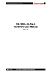
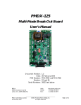
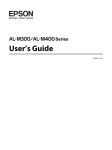
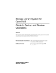
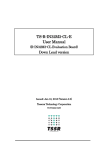
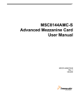
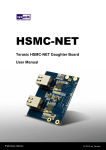
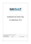
1 CONTENTS Chapter 1 Introduction ..................................................................................................................... 3 1.1 Features ..................................................................................................................................................................... 3 1.2 Getting Help .............................................................................................................................................................. 4 Chapter 2 Architecture ..................................................................................................................... 5 2.1 Block Diagram .......................................................................................................................................................... 6 Chapter 3 Pin Description ................................................................................................................ 7 3.1 HSMC Expansion Connector .................................................................................................................................... 7 Chapter 4 Components ................................................................................................................... 14 4.1 RGMII Ethernet PHY ............................................................................................................................................. 14 4.2 USB 2.0 OTG PHY ................................................................................................................................................. 16 4.3 RS-485/RS-232 Interface ........................................................................................................................................ 17 4.4 CAN Interface ......................................................................................................................................................... 21 4.5 GPIO Interface ........................................................................................................................................................ 21 4.6 DVI Output ............................................................................................................................................................. 22 4.7 SD/SDIO/MMC reader ........................................................................................................................................... 24 4.8 EEPROM ................................................................................................................................................................ 25 4.9 Power ...................................................................................................................................................................... 25 Chapter 5 Appendix ....................................................................................................................... 27 5.1 Revision History ..................................................................................................................................................... 27 5.2 Copyright Statement................................................................................................................................................ 27 2 Chapter 1 Introduction The HSMC Communication card adds key interfaces to support a wide range of industrial, image processing, scientific and measurement requirements. From 10/100/1000 Ethernet PHY, to CAN, RS232, RS485, the HSMC Communication card can quickly get you started with your designs. Also included is a digital DVI transmitter port to display FPGA driven video content. The card allows users to evaluate included interfaces with any HSMC interface host boards. 1.1 Features Figure 1-1 shows the photo of the HSMC Communication card. The important features are listed below: RGMII Ethernet PHY, RJ-45 connector USB 2.0 OTG PHY with ULPI RS-485 x2 with 2x5 0.1″header CAN x2 with DB9 connector GPIO with 2x3 0.1″connector SD Card Socket DVI Transmitter with DVI-D Connector HSMC identification is facilitated via the on board I2C EEPROM. 3 Figure 1-1 Picture of the HSMC Communication card 1.2 Getting Help Here are some places to get help if you encounter any problem: Email to [email protected] Taiwan & China: +886-3-550-8800 Korea : +82-2-512-7661 Japan: +81-428-77-7000 4 Chapter 2 Architecture This chapter describes the architecture of the HSMC Communication card including block diagram and components. A photograph of the HSMC Communication card is shown in Figure 2-1 and Figure 2-2. It depicts the layout of the board and indicates the location of the connectors and key components. Figure 2-1 The HSMC Communication PCB and component diagram Figure 2-2 The HSMC Communication card back side 5 2.1 Block Diagram Figure 2-3 shows the block diagram of the HSMC Communication card. Figure 2-3 Block diagram of the HSMC Communication card 6 Chapter 3 Pin Description This chapter describes the detailed information of the connector interfaces, and the pin description on the HSMC Communication card. 3.1 HSMC Expansion Connector The HSMC Communication card contains a HSMC connector. Figure 3-1, Figure 3-2 and Figure 3-3 show the pin-outs of the HSMC connector on the Mass Storage and Video card. 7 Figure 3-1 Pin-outs of Bank 1 on the HSMC connector 8 Figure 3-2 Pin-outs of Bank 2 on the HSMC connector 9 Figure 3-3 Pin-outs of Bank 3 on the HSMC connector Table 3-1 shows the pin description of the HSMC connector. 10 Table 3-1 The pin mappings of the HSMC connector HSMC Expansion Connector Pin Number Signal Name Direction Function 134 CAN_0_RX Output CAN Receive Data Output 149 CAN_0_TX Input CAN Transmit Data Input 146 CAN_1_RX Output CAN Receive Data Output 97 CAN_1_TX Input CAN Transmit Data Input 157 DVI_CLK Input DVI Transmitter CLK 138 DVI_DATA[0] Input DVI Transmitter Data Bit 0 137 DVI_DATA[1] Input DVI Transmitter Data Bit 1 119 DVI_DATA[10] Input DVI Transmitter Data Bit 10 115 DVI_DATA[11] Input DVI Transmitter Data Bit 11 113 DVI_DATA[12] Input DVI Transmitter Data Bit 12 107 DVI_DATA[13] Input DVI Transmitter Data Bit 13 103 DVI_DATA[14] Input DVI Transmitter Data Bit 14 101 DVI_DATA[15] Input DVI Transmitter Data Bit 15 92 DVI_DATA[16] Input DVI Transmitter Data Bit 16 90 DVI_DATA[17] Input DVI Transmitter Data Bit 17 86 DVI_DATA[18] Input DVI Transmitter Data Bit 18 84 DVI_DATA[19] Input DVI Transmitter Data Bit 19 133 DVI_DATA[2] Input DVI Transmitter Data Bit 2 91 DVI_DATA[20] Input DVI Transmitter Data Bit 20 89 DVI_DATA[21] Input DVI Transmitter Data Bit 21 85 DVI_DATA[22] Input DVI Transmitter Data Bit 22 83 DVI_DATA[23] Input DVI Transmitter Data Bit 23 128 DVI_DATA[3] Input DVI Transmitter Data Bit 3 126 DVI_DATA[4] Input DVI Transmitter Data Bit 4 122 DVI_DATA[5] Input DVI Transmitter Data Bit 5 116 DVI_DATA[6] Input DVI Transmitter Data Bit 6 110 DVI_DATA[7] Input DVI Transmitter Data Bit 7 104 DVI_DATA[8] Input DVI Transmitter Data Bit 8 102 DVI_DATA[9] Input DVI Transmitter Data Bit 9 139 DVI_DE Input DVI Transmitter Data Valid 143 DVI_HSYNC Input DVI Transmitter HSYNC 67 DVI_INTn_OUT Output DVI Transmitter VSYNC 151 DVI_VSYNC Input RGMII Receive Clock 40 ENET_CONN_RX_CLK Output RGMII Transmit Clock 155 ENET_GTX_CLK Input Management Interrupt 98 ENET_INTn Output Management Data Clock 41 ENET_MDC Input Management Data 44 ENET_MDIO Bi-directional Ethernet Hardware Reset 56 ENET_RESETn Input RGMII Receive Control 11 80 ENET_RX_DV Output RGMII Receive Data bit 0 74 ENET_RXD[0] Output RGMII Receive Data bit 1 78 ENET_RXD[1] Output RGMII Receive Data bit 2 53 ENET_RXD[2] Output RGMII Receive Data bit 3 50 ENET_RXD[3] Output RGMII Transmit Control 59 ENET_TX_EN Input RGMII Transmit Data bit 0 68 ENET_TXD[0] Input RGMII Transmit Data bit 1 48 ENET_TXD[1] Input RGMII Transmit Data bit 2 54 ENET_TXD[2] Input RGMII Transmit Data bit 3 47 ENET_TXD[3] Input RS-485/RS-232 Receive Data 152 HSMC_0_RXD Output RS-485/RS-232 Transmit 145 HSMC_0_TXD Input RS-485/RS-232 Receive 114 HSMC_1_RXD Output RS-485/RS-232 Transmit 131 HSMC_1_TXD Input EEPROM Serial Clock 34 HSMC_SCL Input EEPROM Serial Address/ 33 HSMC_SDA Bi-directional GPIO Input Data 150 PIO_0_IN Output GPIO Bi-directional Data 55 PIO_0_OUT[0] Bi-directional GPIO Bi-directional Data 71 PIO_0_OUT[1] Bi-directional GPIO Bi-directional Data 61 PIO_0_OUT[2] Bi-directional RS-485 Request to Send 127 RS485_0_RTS Input RS-485 Request to Send 121 RS485_1_RTS Input SD Card Detection 158 SD_CD Output SD Card Reader Clock 95 SD_CLK Input SD Card Reader Command 144 SD_CMD Bi-directional SD Card Reader Readback 96 SD_CONN_RCLK Output from Level Translator 140 SD_DATA[0] Bi-directional SD Card Reader Data Bit 125 SD_DATA[1] Bi-directional SD Card Reader Data Bit 120 SD_DATA[2] Bi-directional SD Card Reader Data Bit 108 SD_DATA[3] Bi-directional SD Card Reader Data Bit 156 SD_WP Output SD Card Write Protect 39 USB_CONN_CLK Output USB 60MHz Reference 43 USB_DATA[0] Bi-directional USB Data bit 0 49 USB_DATA[1] Bi-directional USB Data bit 1 72 USB_DATA[2] Bi-directional USB Data bit 2 66 USB_DATA[3] Bi-directional USB Data bit 3 62 USB_DATA[4] Bi-directional USB Data bit 4 65 USB_DATA[5] Bi-directional USB Data bit 5 73 USB_DATA[6] Bi-directional USB Data bit 6 77 USB_DATA[7] Bi-directional USB Data bit 7 60 USB_DIR Output USB Data Direction 109 USB_NXT Output USB NXT 12 42 USB_STP Input USB STP 132 - - - 79 - - - Table 3-2 below outlines HSMC power levels that host boards guarantee from on-board power supplies (minimum) according to the HSMC specification. Theses power rails will be delivered via designated pins on the HSMC connector. Table 3-2 HSMC Power Levels WAX Voltage Current Rating 12V 1.0A 12.0W 3.3V_HSMC 2.0A 6.6W Total Wattage 18.6W 13 Chapter 4 Components This chapter gives a simple description of the on board components, such as operational mode, signaling standard. For more detailed information you could refer to its datasheet which is available on manufacturer’s website or from our provided system CD. 4.1 RGMII Ether net PHY This card supports copper RJ-45 10/100/1000 base-T Ethernet using an external Marvell 88E1111. The PHY-to-MAC interface employs an RGMII interface. A block diagram is shown in Figure 4-1 where the MAC is found in the FPGA. Figure 4-1 Marvell RGMII Diagram This device uses 2.5V and 1.1V power rails and requires a 25MHz reference clock (+/-50ppm tolerance) to be driven from a dedicated oscillator. It interfaces to a HALO HFJ11-1G02E model RJ-45 with internal magnetics. The bootstrapping pins are wired to default to “RGMII to copper mode” (HWCFG_MODE[3:0] = 1011). The table below summarizes the pins of the 10/100/1000 Ethernet interface. Signal names and directions are relative to the host board. Table 4-1 Ethernet PHY Interface I/O Signal Name Description Type ENET_GTX_CLK 125MHz GMII Transmit 2.5V CMOS output Clock ENET_TX_CLK 25MHz MII Transmit n/a Clock ENET_TX_ER GMII Transmit Error n/a (tie to GND) 14 ENET_TX_EN GMII Transmit Enable 2.5V CMOS output ENET_TXD(7:4) GMII Transmit Data Bus GND ENET_TXD(3:0) RGMII Transmit Data Bus 2.5V CMOS output ENET_RX_CLK GMII Receive Clock 2.5V CMOS input ENET_RX_ER GMII Receive Error n/a ENET_RX_DV RGMII Receive Control 2.5V CMOS input ENET_RXD(7:4) GMII Receive Data Bus n/a ENET_RXD(3:0) RGMII Receive Data Bus 2.5V CMOS input ENET_CRS GMII Carrier Sense n/a ENET_COL GMII Collision n/a ENET_RESETn Reset 2.5V CMOS input ENET_MDC Management Bus Data 2.5V CMOS input Clock ENET_MDIO Management Bus Data 2.5V CMOS input ENET_INTn Management Bus Interrupt 2.5V CMOS input ENET_MDI(3:0)p/n Media Dependent Interface n/a (to RJ-45 and transformers) ENET_S_CLKp/n SGMII 625MHz Clock n/a ENET_S_OUTp/n SGMII Receive Data n/a ENET_S_INp/n SGMII Receive Data n/a ENET_LED_LINK1 10Mb Link LED n/a (driven to LED) 100Mb Link LED n/a (driven to LED) 1000Mb Link LED n/a (driven to LED) Duplex/Collision LED n/a ENET_LED_RX RX Data Active LED n/a (driven to LED) ENET_LED_TX TX Data Active LED n/a (driven to LED) TMS JTAG Mode Select n/a TCK JTAG Clock n/a TDO JTAG Data Out n/a TDI JTAG Data In n/a TRSTn JTAG Reset Pull to GND with 4.7k_ CONFIG0 Mode configuration pin 0 n/a (tie to GND) CONFIG1 Mode configuration pin 1 n/a (tie to GND) CONFIG2 Mode configuration pin 2 n/a (tie to 2.5V) CONFIG3 Mode configuration pin 3 n/a (tie to GND) CONFIG4 Mode configuration pin 4 n/a (tie to LED_DUPLEX) CONFIG5 Mode configuration pin 5 n/a (tie to LED_LINK100) CONFIG6 Mode configuration pin 6 n/a (tie to LED_RX) 0 ENET_LED_LINK1 00 ENET_LED_LINK1 000 ENET_LED_DUPL EX 15 VDDO I/O Power Pin 2.5V VDDH I/O Power Pin 2.5V VDDX I/O Power Pin 2.5V AVDD Analog Power Input 2.5V DVDD Digital Power Input 1.2V GND - Ground Ethernet PHY The 88E1111 uses a multi-level bootstrap encoding scheme to allow a small set of pins (7) to set up a very large number of default settings within the device. The level encoding scheme is shown in the table below from the Marvel datasheet. The CONFIG[6:0] signals should be tied directly to VDDO, GND or the defined Ethernet pin as described below. Table 4-2 Ethernet PHY Bootstrap Encoding Pin Bit[2:0] VDDO 111 LED_LINK10 110 LED_LINK100 101 LED_LINK1000 100 LED_DUPLEX 011 LED_RX 010 LED_TX 001 VSS 000 Table 4-3 Ethernet PHY Bootstrap Settings Pin Pin Connection Setting Definition CONFIG0 GND 000 MDIO PHY Address bit (2:0) = 000 CONFIG1 GND 000 Enable Pause = 0, PHY Address bits (4:3) = 00 CONFIG2 VDDO (2.5V) 111 Auto-negotiate, advertise all capabilities, prefer CONFIG3 GND 000 Disable crossover, disable CLK125 CONFIG4 LED_DUPLEX 011 Hardware Config Mode Reg (2:0) = 011 CONFIG5 LED_LINK100 101 Disable fiber/copper autosel, enable sleep mode CONFIG6 LED_RX 010 (enable energy detect), Hardware Config Mode 4.2 USB 2.0 OTG PHY The USB 2.0 PHY interface supports the On-The-Go (OTG) protocol and is pinned out with UTMI+Low Pin Interface (ULPI). The USB transceiver will be routed to a mini-AB type connector. 16 Figure 4-2 USB 2.0 Block Diagram 4.3 RS-485/RS-232 Interface There are two multiplexer circuit allowing the ability to switch between an RS-232 or RS-485 interface. This interface contains two independent RS-485 ports and two independent RS-232 ports. Each RS-485 interface is routed to a 2x5 0.1” header and a DB-9 female connector. One RS-232 interface is routed to a 2x5 0.1” header and the second RS-232 interface is routed to a DB-9 male connector. A jumper is used on the board to select between RS-485 port 0 or RS-232 port 0 and RS485 port 1 or RS-232 port 1. 17 Figure 4-3 RS-485/RS-232 Interface Block Diagram RS-485 port 0 is connected to the 2x5 header and DB-9 connector as described in the table below, pin-out and signal description are relative to the header: Table 4-4 RS485 Port 0 Interface Connector Pin-out Pin 2x5 Name Direction Description 1 NC - Not Connected 2 5.0V Power 5V 3 NC - Not Connected 4 NC - Not Connected 5 B Bidirectional inverting driver output/receiver input. 6 A Bidirectional Non-inverting driver output/receiver input. 7 DE Input Driver Enable 8 NC - Not Connected 9 GND Power Signal Ground 10 NC - Not Connected 18 Pin DB9 Name Direction Description 1 GND Power Signal Ground 2 NC - Not Connected 3 B Bidirectional inverting driver output/receiver input. 4 DE Input Driver Enable 5 GND Power Signal Ground 6 5.0V Power 5V 7 NC - Not Connected 8 A Bidirectional Non-Inverting driver output/receiver input. 9 - - - RS-485 port 1 is a profibus type connection. It is connected to the 2x5 header and DB-9 connector as described in the table below, pin-out and signal description are relative to the header: Table 4-5 RS485 (profibus) Port 1 Interface Connector Pin-out Pin 2x5 Name Direction Description 1 NC - Not Connected 2 5.0V Power 5V 3 NC - Not Connected 4 NC - Not Connected 5 A Bidirectional Non-inverting driver output/receiver input. 6 B Bidirectional Inverting driver output/receiver input. 7 DE Input Driver Enable 8 NC - Not Connected 9 GND Power Signal Ground 10 NC - Not Connected - Pin DB9 Name Direction Description 1 GND Power Signal Ground 2 NC - Not Connected 3 A Bidirectional Non-inverting driver output/receiver input. 4 DE Input Driver Enable 5 GND Power Signal Ground 6 5.0V Power 5V 7 NC - Not Connected 8 B Bidirectional Inverting driver output/receiver input. 9 - - 19 RS-232 port 0 is routed to the DB-9 connector as described in Table 4-6 below, pin-out and signal description are relative to the connector: Table 4-6 RS232 Port 0 Interface Connector Pin-out Pin DB9 Name Direction Description 1 NC - Not Connected 2 RXD Output Receive Data Line 3 TXD Input Transmit Data Line 4 NC - Not Connected 5 GND Power Signal Ground 6 NC - Not Connected 7 NC - Not Connected 8 NC - Not Connected 9 NC - Not Connected RS-232 port 1 is routed to the 2x5 header as described in the table below, pin-out and signal description are relative to the connector: Table 4-7 RS232 Port 1 Interface Connector Pin-out Pin DB9 Name Direction Description 1 NC - Not Connected 2 NC - Not Connected 3 RXD Output Receive Data Line 4 NC - Not Connected 5 TXD Input Transmit Data Line 6 NC - Not Connected 7 NC - Not Connected 8 NC - Not Connected 9 GND Power Signal Ground 10 NC - Not Connected 20 4.4 CAN Interface There are two CAN interfaces from the HSMC to two DB9 male connectors. Figure 4-4 CAN Interface Block Diagram Both CAN circuits are connected the same. Table 4-8 CAN DB9 Connector Pin-out Pin DB9 Name Direction Description 1 NC - Not Connected 2 CANL 2 CAN bus line low 3 GND Power Signal Ground 4 NC - Not Connected 5 GND Power Signal Ground 6 GND Power Signal Ground 7 CANH 7 CAN bus line high 8 NC - Not Connected 9 NC - Not Connected 4.5 GPIO Interface There is one 2x3 0.1” header for a GPIO interface. This interface contains 4 single ended lines that can be used for general purpose I/O. However there are some limitations on the IO direction. GPIO_Out lines can be used for bi-directional signals, however GPIO_Input can only be used as a host board input signal. 21 Figure 4-5 GPIO Interface Block Diagram The GPIO head contains 6 pins with the following pin-out: Table 4-9 GPIO Header Pin-out Pin Name Direction Description 1 GPIO_In Input GPIO Input 2 GPIO_Out[0] Bi-Dir GPIO Bi-directional 0 3 GPIO_Out[1] Bi-Dir GPIO Bi-directional 1 4 GPIO_Out[2] Bi-Dir GPIO Bi-directional 2 5 +3.3V - 3.3V Power 6 GND - Ground 4.6 DVI Output DVI Output with be able to support standard DVI-D interface, targeting UXGA resolution, that implies pixel rate of 165MHz. The block diagram is presented on the next figure: *I2C can be shared with other devices Figure 4-6 DVI Interface Block Diagram 22 The purpose of DVI transmitter is to arrange the inbound pixels and generic sync signals to be compatible with DVI interface standard and transmit the encoded data over 4 differential lanes. These lanes are routed to standard DVI connector so it can be connected to imaging device with standard cable. The image data is loaded to transmitter through HSMC interface accompanied by required line and field synchronization signals. Transmitter has I2C port that is used for configuration and diagnostic tasks and it can be shared with other on board I2C enabled devices. In addition this interface is used to communicate with DDC enabled monitors. Here is the pin description of DVI connector: Table 4-10 DVI Connector Pin-out Pin Name Direction Description 1 TMDS Data2- Out Digital red - 2 TMDS Data2+ Out Digital red + 3 TMDS Data2/4 Shield - shield 4 TMDS Data4- Out Not in use 5 TMDS Data4+ Out Not in use 6 SCL Out DDC channel clock 7 SDA Bidir DDC channel data 8 Analog vertical sync Out Not in use 9 TMDS Data1- Out Digital green - 10 TMDS Data1+ Out Digital green + 11 TMDS Data1/3 Shield - shield 12 TMDS Data3- Out Not in use 13 TMDS Data3+ Out Not in use 14 +5V Power Power for monitor during stand-by 15 Ground Power Return for +5V (pin 14) 16 Hot plug detect In Hot plug detect 17 TMDS Data0- Out Digital blue - 18 TMDS Data0+ Out Digital blue + 19 TMDS Data0/5 Shield - shield 20 TMDS Data5- Out Not in use 21 TMDS Data5+ Out Not in use 22 TMDS Clock Shield - shield 23 TMDS Clock+ Out Digital clock - 24 TMDS Clock- Out Digital clock + C1 Analog red Out Not in use C2 Analog green Out Not in use C3 Analog blue Out Not in use C4 Analog horizontal sync Out Not in use C5 Analog ground - Not in use *The signal direction is referred to HSMC card. 23 4.7 SD/SDIO/MMC reader Memory Card Reader interface block diagram is shown on the next figure: Figure 4-7 SD Card Reader Block Diagram This interface should include bi-directional voltage translators in order to be compatible with SD/SDIO cards standard voltage levels. The Storage Cards will be plugged into on-board connector, which will support hot-plugging of the card. The following table describes the SD Card pin-out: Table 4-11 SD Card Reader Socket Pin-out Pin Name Direction Description 1 CD/DAT3 Bidir Card Detect/Data line 2 CMD Bidir Command/Response 3 Vss1 Power Ground 4 Vdd Power Supply Voltage 5 CLK Input Clock 6 Vss2 Power Ground 7 DAT0 Bidir Data line 0 8 DAT1 Bidir Data line 1 9 DAT2 Bidir Data line 2 In addition to card interface, the card socket contains two physical switches that used to detect card insertion/de-insertion and status on the write protect switch on the card. The status of these switches is routed to HSMC interface as well. SD Card bus time diagram is shown below: 24 Figure 4-8 SD Card Signal Timing 4.8 EEPROM The Microchip Technology Inc. 24AA08/24LC08B (24XX08*) is an 8 Kbit Electrically Erasable PROM. The device is organized as four blocks of 256 x 8-bit memory with a 2-wire serial interface. Low-voltage design permits operation down to 1.7V, with standby and active currents of only 1 μA and 1 mA, respectively. The 24XX08 also has a page write capability for up to 16 bytes of data. The 24XX08 is available in the standard 8-pin PDIP, surface mount SOIC, TSSOP, 2x3 DFN, 2x3 TDFN and MSOP packages, and is also available in the 5-lead SOT-23 package. 4.9 Power There are two power rails that are supplied through HSMC connector +12V and +3.3V. All the required on-board voltages are generated from these voltage rails. However due to possible excessive power requirements to support two hard drives, there is an option to supply the power from external power supply through power plug. On board DC/DC regulator will generate +12V and supply it to all the downstream power rails. This option is selected by on-board jumper. 25 Figure 4-9 Power Tree 26 Chapter 5 Appendix 5.1 Version V1.0 V1.1 5.2 Revision Histor y Change Log Initial Version (Preliminary) Modify Table 4-9 Copyright Statement Copyright © 2011 Terasic Technologies. All rights reserved. 27