1
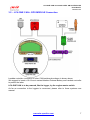
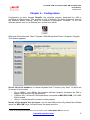
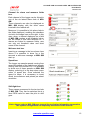
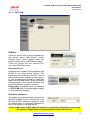
LCU-ONE CAN connected to
MXL QM and EVO3 QM
User Manual
LCU-ONE CAN connected to MXL QM and EVO3 QM
User Manual
Release 1.04
INDEX
Chapter 1 – LCU–ONE ....................................................................................................... 2 1.1 – Part number ........................................................................................................................................ 2 Chapter 2 – LCU–ONE and Lambda probe mounting ..................................................... 3 Chapter 3 – Connection to MXL – EVO3 QM ................................................................... 5 3.1 – LCU-ONE CAN Connection ............................................................................................................... 5 3.2 – LCU-ONE CAN + GPS MODULE Connection ................................................................................... 7 Chapter 4 – Configuration ................................................................................................. 8 4.1 – Select configuration ........................................................................................................................... 9 4.2 – Channels ........................................................................................................................................... 10 4.3 – System configuration....................................................................................................................... 11 4.3.1 – Configuring MXL QM .................................................................................................................. 11 4.3.2 – EVO3 QM .................................................................................................................................... 13 Chapter 5 – Configuration on MXL QM – EVO3 QM ...................................................... 14 Chapter 6 – Data Visualisation on MXL QM/EVO3 QM.................................................. 18 6.1 – Data Visualisation on MXL QM ....................................................................................................... 18 6.2 – Data Visualisation on EVO3 ............................................................................................................ 18 Chapter 7 – Data Analysis with QMAn ........................................................................... 19 Appendix – Technical drawings ..................................................................................... 20 www.aim-sportline.com
1
LCU-ONE CAN connected to MXL QM and EVO3 QM
User Manual
Release 1.04
0
Chapter 1 – LCU–ONE
LCU-ONE is a lambda controller unit for the wide band BOSCH LSU 4.9 Lambda probe; it
fits petrol (2 and 4 strokes), diesel and methane engines as well as alcohol based fuel
engines. It is intended to check lambda probe proper working as well as to transmit the
Air/fuel ratio values providing MXL Pro/Pista QM (from here onwards MXL QM) and
EVO3 Pro/Pista QM (from here onwards EVO3 QM) with lambda values through the CAN
bus.
Lambda value is defined as: LAMBDA =(A/F)/(A/F) Stoichiometric
Where:
A= incoming part of air;
F= parts of petrol the carburettor introduces in the engine;
A / F Stoichiometric = parts of air needed to burn Stoichiometric F;
Gasoline, for example, needs 14,57 parts of air to completely burn a part of gasoline,
obtaining Lambda value= 1 read by the probe.
LCU–ONE controller can detect lambda values in a range from 0.65 to 1.6 (free air).
It is reminded that LAMBDA values lower than 1 means a rich mixture, while
LAMBDA values higher than 1 means a lean mixture.
Wide band Lambda probe need to be heated to work properly and not poisoned with
exhaust gas. LCU-ONE controller precisely manages the probe heater so to keep
temperature value within the optimum working range.
During its working period, Lambda probe used with LCU-ONE controller becomes very hot
(around 700-800 °C, 1292-1472 °F); it is thereby necessary AVOIDING:
•
•
Touching it;
Placing it in contact with flammable stuff or fuel.
Please note:
disrespect of these precautions can cause shocks, burnings or explosions.
8
1.1 – Part number
Kits part number are:
•
•
Controller LCU-ONE (Complete kit with Lambda probe)
BOSCH LSU 4.9 Lambda probe
www.aim-sportline.com
X08LCU03K0
XO5LSU490
2
LCU-ONE CAN connected to MXL QM and EVO3 QM
User Manual
Release 1.04
1
Chapter 2 – LCU–ONE and Lambda probe mounting
LCU-ONE controller should be installed in a flat location and far from heat sources; it
should be mounted steady using the suited bracket.
The wiring has to be arranged so to be far from heat sources.
BOSCH LSU 4.9 lambda probe should be installed on the vehicle exhaust pipe using a
specific adaptor that comes with the kit and should be welded on the same pipe. The
probe should be sufficiently near to the engine.
Probe working temperature should not exceed 900°C (1652°F), neither be exposed to the
free flame coming from the exhaust system.
Probe installation angle should be of at least 10° to avoid liquid condensation stuff to come
in contact with the probe, polluting it.
When the probe has been installed, do not let the cable pass close to heat sources (the
exhaust pipe for example).
BOSCH LSU 4.9 probe auto-calibrates: no calibration is then required.
Solvents or additives should not be used to clean the probe connector. We would thereby
suggest to remove it from the dragster when cleaning the vehicle, to avoid probe pollution
caused by detergents.
REMINDER: never switch the vehicle on with Lambda probe installed and not connected
to a correctly working LCU-ONE controller: a probe not heated and exposed to exhaust
gas would be irremediably damaged.
Attention: BOSCH LSU 4.9 Lambda probe has been designed to be used with
unleaded or diesel engines. It can be used with other kinds of engine too, but its
duration needs to be verified by the user with specific tests.
www.aim-sportline.com
3
LCU-ONE CAN connected to MXL QM and EVO3 QM
User Manual
Release 1.04
We suggest to install Lambda controller and the related probe as shown in the following
pictures.
Moreover we advise to install a 10 Ampere fuse in series between the external battery and
lambda controller.
We would suggest to install the probe in the exhaust pipe (see picture below):
www.aim-sportline.com
4
LCU-ONE CAN connected to MXL QM and EVO3 QM
User Manual
Release 1.04
2
Chapter 3 – Connection to MXL – EVO3 QM
LCU-ONE CAN can be connected to all MXL and EVO3 QM.
Warning: connect LCU-ONE to MXL QM or EVO3 QM OFF.
9
3.1 – LCU-ONE CAN Connection
Lambda controller connection scheme is showed above.
To protect Lambda Controller we suggest to insert one 10 A fuse for each controller in
series between external battery and Lambda controller.
LCU-ONE CAN is to be powered, like the logger, by the engine master switch.
As far as connection with the loggers is concerned, please refer to those systems user
manuals.
www.aim-sportline.com
5
LCU-ONE CAN connected to MXL QM and EVO3 QM
User Manual
Release 1.04
In case more than one Lambda Controller are to be connected, for a better engine control
(one probe for each engine bank or even one probe for each cylinder), peripherals
connection scheme is the following:
Each Lambda controller has to be connected to the battery.
We would suggest to protect each Lambda controller with a 10 A fuse.
When MXL/EVO3 QM is switched off all peripherals are automatically switched off.
www.aim-sportline.com
6
LCU-ONE CAN connected to MXL QM and EVO3 QM
User Manual
Release 1.04
13
3.2 – LCU-ONE CAN + GPS MODULE Connection
Lambda controller connection to other CAN peripherals scheme is shown above.
We suggest to insert a 10 A fuse in series between External Battery and Lambda controller
to protect the latter.
LCU-ONE CAN is to be powered, like the logger, by the engine master switch.
As far as connection to the loggers is concerned, please refer to those systems user
manual.
www.aim-sportline.com
7
LCU-ONE CAN connected to MXL QM and EVO3 QM
User Manual
Release 1.04
3
Chapter 4 – Configuration
Configuration is done through DragOn, the software properly developed by AIM to
configure its QM products. This software is rich of features: we would suggest to practice
the software before starting, using its advanced configuration functions. To run the
software double click on its desktop icon, shown here below
Otherwise follow this path: Start \ Program \ AIM Racing Data Power \ Dragster \ DragOn.
This window appears.
On the left of the window is a vertical keyboard with 7 buttons, only three 1 of which are
of interest in this tutorial:
•
•
•
“Go to QMAn”: runs QMAn, the analysis software properly developed by AIM to
analyse data stored in its QM products;
“CAN-net info”: shows all CAN expansions connected to MXL/EVO3 QM, LCU-ONE
CAN included;
“Online”: checks that all the network works properly.
On top of the window four top layers: one for each QM product. By default the software
opens on “MXL QM” layer. All layers have the same structure.
1
As far as all other keyboard buttons are concerned, refer to MXL/EVO3 QM user manual.
www.aim-sportline.com
8
LCU-ONE CAN connected to MXL QM and EVO3 QM
User Manual
Release 1.04
On top of each layer is a photo of the logger the layer refers to. On its right are:
•
•
•
“Transmit” button: transmits the configuration to the logger;
“Receive” button: reads the configuration of a logger connected to the PC and
stores it in the configuration database;
“Current configuration” table: shows all the most important information concerning
the configuration user is working on.
To transmit a configuration:
•
•
•
connect the logger to the PC USB port through the included USB cable;
turn the logger on;
click on “Transmit”.
Warning: transmission of a configuration deletes all data stored in the logger
memory. It is thereby recommended to make data download before transmitting a
configuration to the logger.
To receive a configuration:
•
•
•
connect the logger to the PC USB port through the included USB cable;
turn the logger on;
click on “Receive” button
Configuration database will show one more row, highlighted in yellow, on bottom of the
central table of “Select Configuration” layer.
10
4.1 – Select configuration
DragOn software features a configuration database to trace all possible data acquisition
settings. In “Select configuration” layer is a top keyboard that allows the user to:
•
•
•
•
•
New: create a new configuration
Delete: delete an existing configuration
Clone: copy an existing configuration
Import: import a configuration in the database
Export: export a configuration
Under the keyboard is a central table whose columns are:
•
•
•
•
•
•
•
N: progressive number of the configuration in this database; this digit cannot be
modified and is attributed to the configuration when it is created/imported/cloned
Installation Name: shows the configuration name; to edit it double click on the cell.
ECU Manufacturer: if the vehicle the logger is connected to is equipped with an
ECU supported 2 by DragOn software, it is possible to select its manufacturer in the
pop up menu that appears double clicking on the cell; default setting is “none”.
ECU Model: if the vehicle the logger is connected to is equipped with an ECU
supported by DragOn software, it is possible to select its model in the pop up menu
that appears double clicking on the cell; default setting is “none”.
Vehicle Name: shows the vehicle name; double click on the cell to change it.
Created: creation date of the configuration
Tot. Expansions: number of CAN expansions the logger is connected to.
2
To know if the ECU installed on the vehicle is supported by DragOn software refer to ECU-AIM logger Pdf
document available on aim website download area/documentation.
www.aim-sportline.com
9
LCU-ONE CAN connected to MXL QM and EVO3 QM
User Manual
Release 1.04
14
4.2 – Channels
In order to correctly sample data transmitted by any additional sensor connected to the
logger, each sensor needs to be connected to a proper analog channel and configured. To
do so, it is necessary to set “Channels” layer. First of all activate it as shown here below:
Central in this layer is channels table, whose columns are:
Channel identifier: shows default channel identifier and cannot be modified.
Enabled\Disabled: shows channel status; “enabled” means the channel will be
sampled, “disabled” means it won’t. To change channel status check/un-check the
related checkbox.
• Channel name: shows the channel name: double click on the cell to change it.
• Sampling frequency: shows logger sampling frequency of that channel.
Note: the higher is total sampling frequency, the less is the available time (red
circled in the above figure), because memory fills up quicker. Each channel is set on
a default sampling frequency that depends on the type of sensor installed on that
channel. It is suggested to be careful changing this value, because it may impact on
the quantity of runs the logger can store. AIM QM products can acquire up to
2000Hz total sampling frequency (max 500Hz per channel depending on the sensor
installed; thermocouples, for example, cannot sample more than 100Hz).
• Sensor type: shows the type of sensor installed on that channel; to select the right
sensor double click on the cell and scroll the pop up menu.
• Measure unit: shows unit of measure used to sample that channel. It can be
changed double clicking on the cell.
3
• Low / High Scale: shows the range of values used to draw QMAn graphs.
Some channels (i.e. speed) need additional information to properly acquire data. In this
case additional panel(s) appears over channels table. In the above image the logger has
one speed and the related panel needs to be filled in.
•
•
3
QMAn is the analysis software properly developed by AIM to analyse data stored by its QM products. It is
available for free download on AIM website download area/software.
www.aim-sportline.com
10
LCU-ONE CAN connected to MXL QM and EVO3 QM
User Manual
Release 1.04
15
4.3 – System configuration
System configuration is the most important operation to make in order to correctly sample
data and show them on the logger display (if available). This layer layout depends on the
logger to be configured: activate “System configuration layer” and fill in the window.
16
4.3.1 – Configuring MXL QM
RPM box:
If the info comes from a sensor installed on
the vehicle, press “AIM sensor”: ‘multiply
factor’ case enables: insert the proper
multiply factor and RPM max value.
In case this info comes from the vehicle
ECU, insert only RPM Max value.
Moreover it is possible to link an alarm led
to an over-rev threshold value to be
inserted in the related case.
Gear sensor box:
The engaged gear number can be sampled
and shown or not (In this case press “None”
button). As shown here on the right the
information can come from a gear
potentiometer installed on the vehicle, from
the ECU or can be calculated through an
algorithm based on RPM and speed. Press
the button corresponding to the vehicle
situation and insert highest gear number if
required.
www.aim-sportline.com
11
LCU-ONE CAN connected to MXL QM and EVO3 QM
User Manual
Release 1.04
Channel for alarm and measure fields
box:
Each channel of the logger can be linked to
one of the six lateral alarm leds of MXL
QM.
These channels can also be displayed on
MXL QM display with the short name
inserted in the related cell.
Moreover it is possible to link alarm leds to
the fields displayed, enabling the checkbox
circled in the image here on the right. In this
case, when a channel displayed on a field
of MXL QM reaches a set threshold value,
the led linked to that field switches on. If
alarms are linked to measure fields, user
can only set threshold value and short
name of the channel.
Welcome text box:
Inserting a message in the box shown here
above it is possible to show for a few
seconds a welcome message at MXL QM
start up.
Speed box:
The logger can sample speeds coming from
sensors installed on the vehicle and speeds
coming from the vehicle ECU. It is possible
to show one of these speeds on MXL QM
display, selecting it in the drop down menu
menu of speed box. Once selected the
speed to show, it is necessary to insert
wheel circumference and pulses per wheel
revolution.
Shift light box:
These cases correspond to the ten top leds
of MXL QM. They can be switched on at a
fixed RPM value to warn the pilot to shift
gear.
Note: always refer to MXL QM user manual for any further information concerning
the system configuration not expressly discussed in this tutorial.
www.aim-sportline.com
12
LCU-ONE CAN connected to MXL QM and EVO3 QM
User Manual
Release 1.04
17
4.3.2 – EVO3 QM
RPM box:
If this info comes from a sensor installed on
the vehicle, press “AIM sensor” button:
‘Multiply factor’ case enables: insert the
proper multiply factor and RPM max value.
If this info comes from the vehicle ECU,
only insert RPM Max value.
Gear sensor box:
Engaged gear number can be sampled and
shown or not (press “None” button). The
information can come from the ECU, from a
gear potentiometer installed on the vehicle,
or can be calculated through an algorithm
based on RPM and speed. Press the button
corresponding to the vehicle situation and
insert highest gear number if required.
Please note: calculated gears are available
on EVO3 QM only if a showing gear display
is connected to the logger.
Reference speed box:
The logger can sample speeds coming from
sensors installed on the vehicle and from
the vehicle ECU. Reference speed is used
to calculate gear: it is strongly suggested to
select the speed of a driving wheel.
Note: always refer to MXL QM user manual for any further information concerning
the system configuration not expressly discussed in this tutorial.
www.aim-sportline.com
13
LCU-ONE CAN connected to MXL QM and EVO3 QM
User Manual
Release 1.04
4
Chapter 5 – Configuration on MXL QM – EVO3 QM
To use LCU-ONE CAN with MXL/EVO3 QM you need to configure it using DragOn
software. Please refer to the installation manual for further information about the software.
To configure Lambda Controller run the software and select the logger manager layer as
explained before. To configure LCU-ONE it is necessary to activate “CAN-Expansions
configurator” layer, present in all loggers manager layer
In case of very first configuration the layer appears empty as shown below.
Press “Add Expansion” button and the
window here on the right appears.
Select LCU-ONE CAN (only CAN). The
field under the keyboard enables, press
“Get serial number from a connected
expansion” button and the system
reads the LCU-ONE serial number. It is
also possible to manually insert the
serial number getting it from LCU-ONE.
This operation is to be repeated as
many times as many Lambda probes
are connected.
www.aim-sportline.com
14
LCU-ONE CAN connected to MXL QM and EVO3 QM
User Manual
Release 1.04
The layer will be modified as shown below and as many additional layers as many lambda
probes have been added appear.
In case serial number has not been get, press “Get serial number from a connected
expansion” button.
Warning: this operation is necessary to be able to transmit the configuration to the logger.
LCU-ONE layer is shown above.
On top
•
Name of expansion configuration (6 characters max.) and serial number fields.
Inserting a configuration name the layer label is modified live.
Central in the page a table shows LCU-ONE channels. The table has 7 columns.
•
•
•
•
•
•
Enabled/Disabled: shows the channel status (enabled/disabled) and can be
modified checking or un-checking the related checkbox. LCC_lambda (lambda
value) and LCC_AFR (AFR value) channels are enabled by default.
Channel name: shows the channel name and can be modified double clicking on
the cell, which becomes editable.
Sampling frequency: shows the channel sampling frequency and can be set
selecting the desired value from the pop up menu that appears double clicking on
the cell (accepted values are from 1 to 50 Hz).
Sensor Type: shows the sensor installed on that channel and cannot be modified.
Measure Unit: shows the selected unit of measure of that channel and can be
modified double clicking on the cell.
Low/High scale: shows the channel high and low scale and can be modified double
clicking on the cells, which become editable.
Under the table is “Multiplier to calculate AFR from lambda” field. It allows the user to
change the used fuel and to insert a new one. Select the used fuel to see its AFR value.
www.aim-sportline.com
15
LCU-ONE CAN connected to MXL QM and EVO3 QM
User Manual
Release 1.04
In case a fuel not included in the database is being used and only in case its
Stoichiometric value is known, press “Add custom value” button and the window shown
below appears.
Fill in the window with Multiplier value and related legend. Press “Add new item to list” and
then “Save”.
Likewise, selecting a multiplier from the left box labelled “Custom multiplier value list” and
pressing “Remove selected item from list” button the multiplier is removed.
Once enabled/disabled the channels, it is possible to decide if and what Lambda channels
to show on the display, depending on the logger and on the connected peripherals. In case
of an MXL QM, Lambda channels can be shown setting them in “System Configuration”
layer as shown here below. In the example enabled channels are: LCC_Lambda,
LCC_Diagn and LCC_AFR AND each of them can be shown in one field of the display.
www.aim-sportline.com
16
LCU-ONE CAN connected to MXL QM and EVO3 QM
User Manual
Release 1.04
In case of an EVO3 QM, data visualisation is only possible if the logger is connected to a
Formula Steering Wheel or to a MyChron3 Dash and displayed channels are set in that
display configuration, as shown below.
Note: LCC_diagnosys channel shows LCU-ONE working status and can show up to four
messages:
•
•
•
•
0: status OK
1: probe not connected
2: +12V short circuit
3: GND short circuit
The configuration is now ready to be transmitted to the logger.
Warning: configuration has to be repeated for all LCU-ONE connected to the logger.
Press “Transmit” button on DragOn top keyboard. If the transmission is ok no message is
shown. If, LCU-ONE serial number has not been get, the window here below appears. It
tells the user that no serial number has been assigned to the connected expansion. Close
this window button and get the expansion serial number as explained before.
www.aim-sportline.com
17
LCU-ONE CAN connected to MXL QM and EVO3 QM
User Manual
Release 1.04
5
11
Chapter 6 – Data Visualisation on MXL QM/EVO3 QM
6.1 – Data Visualisation on MXL QM
Lambda channels visualisation on MXL QM works exactly like the visualisation of any
other MXL QM channel: switch from one page to the other is made using “MEM/View”
button. Please refer to MXL QM user manual for further information. In the image below
lambda value is 0.955 and assigned Short Name is LAM.
Powering MXL QM and Lambda controller on at the same time, LCU-ONE CAN is
recognised at start-up and probe warm-up procedure starts. During this period the
controller takes the probe to its working temperature (until around 780 °C – 1436 °F).
During warm-up (around 20-30 seconds), displayed lambda value is 1.00.
When the probe is 100% working, displayed value turns, with the engine off, into 1.60 (free
air value).
Warning: it is reminded that LCU-ONE, like the logger, has to be powered by the engine
master switch.
12
6.2 – Data Visualisation on EVO3
Lambda channels visualisation on EVO3 QM works exactly as the visualisation of any
other EVO3 QM channel and is thereby possible only if the logger is connected to a
display. The only displays that show Lambda value are MyChron3 Dash and Formula
Steering wheel. Please refer to EVO3 QM user manual for further information. In the
image below Lambda value is 0.95 and the field is labelled “λ”
Switching EVO3 QM on Lambda controller is recognised at start up and probe warm-up
procedure starts. During this period the controller takes the probe to its working
temperature (until around 780 °C – 1436 °F).
During warm-up (around 20-30 seconds), displayed lambda value is 1.00.
When the probe is 100% working displayed value turns, with the engine off, into 1.60 (free
air value).
Warning: it is reminded that LCU-ONE, like the logger, has to be powered by the engine
master switch.
www.aim-sportline.com
18
LCU-ONE CAN connected to MXL QM and EVO3 QM
User Manual
Release 1.04
6
Chapter 7 – Data Analysis with QMAn
During data analysis, the presence of Lambda controller adds two channels to measures
and laps toolbar (as shown below):
Lambda: shows lambda value recorded during the session;
Lambda _Temp: indicates the probe internal working temperature
To better analyse carburetor values we would suggest to show XY diagram of Lambda
probe with RPM values on abscissa axle and Lambda values on ordinate axle.
This way a more immediate reading of carburetion status is available.
www.aim-sportline.com
19
LCU-ONE CAN connected to MXL QM and EVO3 QM
User Manual
Release 1.04
7
Appendix – Technical drawings
www.aim-sportline.com
20
LCU-ONE CAN connected to MXL QM and EVO3 QM
User Manual
Release 1.04
www.aim-sportline.com
21