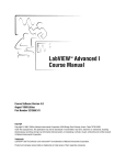
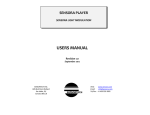
1
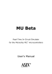
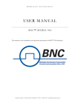
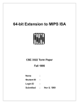
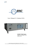
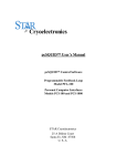
•
20 independent delay channels,
•
100 ps delay resolution,
•
10 seconds delay range,
•
Adjustable output level, polarity and width.
BNC Ed. 1
User's manual - 745-20C-T
Date : 05/02/2013
TABLE DES MATIERES
EDITION
3
REFERENCE DOCUMENTS ......................................................................................................................................... 3
1.
GENERAL INFORMATION .......................................................................................................................... 4
1.1.
DESCRIPTION ...............................................................................................................................................
1.2.
INSTALLATION .............................................................................................................................................
1.2.1.
Power source.......................................................................................................................................
1.2.2.
Power cord ..........................................................................................................................................
1.3.
OPERATING TEMPERATURE ..........................................................................................................................
1.4.
RACK MOUNTING INFORMATION ..................................................................................................................
1.5. SELF-TEST ....................................................................................................................................................
1.6.
OPTIMAL PERFORMANCE..............................................................................................................................
4
5
5
5
5
5
5
5
2.
SPECIFICATIONS ........................................................................................................................................... 6
3.
OPERATING INFORMATION ...................................................................................................................... 7
3.1.
PRINCIPLE – BLOCK DIAGRAM .....................................................................................................................
3.2.
LOCAL COMMAND AND PARAMETER ............................................................................................................
3.3.
FRONT PANEL OPERATION SUMMARY ...........................................................................................................
3.3.1.
LCD .....................................................................................................................................................
3.3.2.
AUX 1 to 3 ...........................................................................................................................................
3.4.
REAR PANEL OPERATION SUMMARY...........................................................................................................
3.4.1.
Power switch .....................................................................................................................................
3.4.2.
Ethernet port (LAN)...........................................................................................................................
3.4.3.
Trigger input (TRIG IN) ....................................................................................................................
3.4.4.
Trigger ouptut (T0)............................................................................................................................
3.4.5.
Clock output (CLK OUT) ..................................................................................................................
3.4.6.
Clock input (CLK IN) ........................................................................................................................
3.4.7.
Trigger output T1 to T20 ...................................................................................................................
3.5.
DEFAULT VALUE ........................................................................................................................................
4.
CONNECTING TO THE INSTRUMENT VIA ETHERNET .................................................................... 12
4.1.
GENERALITY ..............................................................................................................................................
4.2.
COMMAND STRUCTURE ..............................................................................................................................
4.2.1.
*IDN? ................................................................................................................................................
4.2.2.
DELAY...............................................................................................................................................
4.2.3.
TRIG ..................................................................................................................................................
4.2.4.
VOLTAGE LEVEL.............................................................................................................................
4.2.5.
WIDTH ..............................................................................................................................................
4.2.6.
POLARITY.........................................................................................................................................
4.2.7.
FREQUENCY....................................................................................................................................
4.2.8.
RUN...................................................................................................................................................
4.2.9.
STAT ..................................................................................................................................................
4.2.10. IP adress............................................................................................................................................
4.2.11. Net mask adress.................................................................................................................................
4.2.12. GW adress .........................................................................................................................................
4.3.
REMOTE CONTROL VIA INTERNET...............................................................................................................
5.
7
8
9
9
9
10
10
10
10
10
10
10
10
11
12
12
13
13
14
14
15
15
16
16
17
18
18
19
20
SOFTWARE .................................................................................................................................................... 21
BERKELEY NUCLEONICS
Page - 2 / 22-
User's manual - 745-20C-T
BNC
Ed. 1
Date : 05/02/2013
Edition
Write by :
Date & Visa : Massy, le
MONNIER-BOURDIN
Technical manager
Ed.
Date
Description
1
1/2013
Creation
Reference documents
Documents
Reference
DR 1
DR 2
DR 3
DR 4
BERKELEY NUCLEONICS
Page - 3 / 22-
User's manual - 745-20C-T
1.
BNC Ed. 1
Date : 05/02/2013
GENERAL INFORMATION
1.1.
Description
The 745-20C-T Digital Delay Generator provides twenty independent delayed output pulses.
Delays up to 10 seconds may be programmed with 100ps resolution and channel to channel jitter
less than 50 ps rms.
BNC outputs deliver pulses, with adjustable level (3 to 6V) and polarity, into 50Ω load.
A trigger out signal (T0) is provided to reference the delayed outputs in different operation mode.
745-20C-T parameters may be remote controlled via an Ethernet interface (10/100Mb/s) (basic
commands or Web page).
Instrument Options
Option 1
Clock output (same frequency as specified clock input)
Option 2
2.5 to 10 V channels, 1 ns rise time, positive polarity
Option 3
Amplitude up to 20 V, adjustable
Option 4
Maximum amplitude up to 32V (fixed)
Option 5
1 ps resolution
Option 6
Front panel for local control (touchscreen)
Other
trigger source saved after shut down, Immediate modification of output pulse
without validation, specific options available upon request.
Package contents:
The box you receive should contain the
following: o 745-20C-T
instrument,
o Power cable, o
User’s manual,
o
CD containing DLL and Labview driver.
BERKELEY NUCLEONICS product:
For more information about Berkeley Nucleonics product see our web site:
www.berkeleynucleonics.com
BERKELEY NUCLEONICS
Page - 4 / 22-
User's manual - 745-20C-T
1.2.
BNC Ed. 1
Date : 05/02/2013
Installation
1.2.1. Power source
The 745-20C-T can be operated from 90 VAC to 240 VAC nominal supply source.
The maximum power consumption of the 745-20C-T is 80 W.
1.2.2. Power cord
The 745-20C-T comes with a removable power cord for European usage. It has a three
contact plug for connection to both the power source and protective ground.
1.3.
Operating temperature
The 745-20C-T can be operated where the ambient air temperature is 0°C to 35°C and can be
stored in ambient temperature from - 10°C to + 60°C. The 745-20C-T is cooled by air circulation.
To prevent instrument damage a clearance of 2 inches on the side and 1 inch on the rear must be
maintained for proper cooling.
1.4.
Rack mounting information
The 745-20C-T will fit a 19 inch rack.
1.5.
Self-test
The model, firmware version, serial numbers for the units and self-test will be displayed a certain
time after the power is applied, depending on the ambient temperature. The self-test should not
exceed 1 minute.
1.6.
Optimal performance
To ensure optimal performance, it is recommended to wait 1 hour after the equipment’s switching
on.
BERKELEY NUCLEONICS
Page - 5 / 22-
BNC Ed. 1
User's manual - 745-20C-T
2.
Date : 05/02/2013
SPECIFICATIONS
Delays
Channels
20 independent delay channels
Range
0 to 10 seconds
Resolution
100 ps
RMS Jitter
< 50 ps + delay x 10
-7
rms
Internal time base
Frequency
CLK RF
Stability
10
-8
Trigger
Single shot source SS1 and
SS2 (synchronous of F3)
Ethernet or Web page or trigger input
Synchronous
triggers
3 frequencies: F1> F2 > F3
repetitive
F1: 1000, 500, 200, 100, 50, 20, 10, 5, 2 Hz
F2: 200, 100, 50, 20, 10, 5, 2, 1, 0.5 Hz
F3: 50, 20, 10, 5, 2, 1, 0.5, 0.2, 0.1 Hz
Outputs
Delayed output (T1 to T20)
Reference output (T0)
Positive or negative pulse into 50 Ω,
Amplitude 3 to 6 V , resolution: 10 mV,
Rise time : < 5 ns,
Tm :
Fall time: < 10 ns,
< 3 ns
Width: 100 ns to 300 ms
Connector type BNC,
Level: 3 to 6 V
Width :
100 ns to 300 ms
Positive pulse into 50 Ω, amplitude 3 to 6V, resolution 10 mV
Rise time < 5 ns, fall time < 10 ns, width 100ns to 300 ms
Connector type BNC
CLK RF / 2 clock output
(option)
Frequency: CLK RF / 2, > 1V / 50 Ω,
Connector type BNC,
Interface
Front panel (option), Ethernet 10/100 Mb/s, Internet (Web page)
General
Power Required
90 – 220 V / 50 – 60 Hz / 1 A.
Weight
Net: < 10 kg
Dimensions
19’’, 2 U, 320 mm without handles
BERKELEY NUCLEONICS
Page - 6 / 22-
BNC Ed. 1
User's manual - 745-20C-T
3.
Date : 05/02/2013
OPERATING INFORMATION
3.1.
Principle – Block diagram
The principle of the programmable delay generator is described in the figure bellow:
CLK RF
Clock
Delay Reference
T0
T1
Trigger
(TRIG IN)
Clock
Controller
20 Digital Delays
T2
Analog
Vernier
T3
T20
KeyBoard
Display
Interface Controller
Ethernet
The sequence follows 3 phases:
•
After on insertion delay a reference pulse appear at the “T0” output,
•
Following the reference a pulse will appear on each channel after a specified delay,
•
At the end of sequence, after last delayed pulse outputs, the delay generators are initiate.
When a sequence is in progress the instrument will not respond to a trigger event.
Each delayed values output pulse (T1 to T20) can be independently adjustable in level and width.
All values (delay, level, width) are saving when shut down the equipment, except the trigger source
(option). After the power on, all trigger sources are off (INH).
BERKELEY NUCLEONICS
Page -7 / 22 -
BNC Ed. 1
User's manual - 745-20C-T
3.2.
Date : 05/02/2013
Local command and parameter
The following chart described the trigger source, amplitude and width for each trigger out T0 and delayed
output T1 to T20:
745-20C-T
T0 to T20
SOURCE
Inhibited (INH)
Repetitive F1 (F1)
TRIGG
ER
Repetitive F2 (F2)
Repetitive F3 (F3)
Single Shot 1 (SS1)
Single Shot 2 (SS2)
AMPLITUDE
3 V to 6 V in 10 mV steps
WIDTH
100 ns to 300 ms in CLK RF steps
BERKELEY NUCLEONICS
Page -8 / 22 -
User's manual - 745-20C-T
3.3.
BNC Ed. 1
Date : 05/02/2013
Front panel operation summary
The 745-20C-T front panel consists of a LCD display and 3 BNC.
BNC 745-20C-T
3.3.1. LCD
The LCD is screen tactile (option).
3.3.2. AUX 1 to 3
TBD.
BERKELEY NUCLEONICS
Page -9 / 22-
User's manual - 745-20C-T
3.4.
BNC Ed. 1
Date : 05/02/2013
Rear panel operation summary
All input or output connections to the 745-20C-T are made on the rear panel.
3.4.1. Power switch
The unit is turned on by depressing the POWER button. The 745-20C-T can be operated
from 90 to 240 V at a line frequency of 50 – 60 Hz.
3.4.2. Ethernet port (LAN)
The RJ45 Ethernet rear panel connector allows a computer to control the 745-20C-T.
3.4.3. Trigger input (TRIG IN)
BNC connector for application of the trigger input signal that generates the single shot
sequence.
3.4.4. Trigger ouptut (T0)
BNC connector for signal output. This is the output reference. This should be terminated in
50Ω.
3.4.5. Clock output (CLK OUT)
BNC connector for signal output. This is the 85 MHz reference. This should be terminated in
50 Ω.
3.4.6. Clock input (CLK IN)
BNC connector for signal input. This is the 85 MHz reference.
3.4.7. Trigger output T1 to T20
BNC connectors for delayed signal outputs. This should be terminated in 50 Ω.
BERKELEY NUCLEONICS
Page -10 / 22 -
User's manual - 745-20C-T
3.5.
BNC Ed. 1
Date : 05/02/2013
Default value
The default values are the following:
•
IP ADRESS : 99.0.0.18,
•
GATEWAY ADRESS : 99.0.0.01,
•
NET MASK : 255.0.0.0,
•
F1 : 1000 Hz,
•
F2 : 100 Hz,
•
F3 : 10 Hz
•
Level: 5.00 V,
•
Width: 500 ns.
BERKELEY NUCLEONICS
Page -11 / 22 -
BNC Ed. 1
User's manual - 745-20C-T
4.
Date : 05/02/2013
CONNECTING TO THE INSTRUMENT VIA ETHERNET
4.1.
Generality
For connecting over the LAN, you would do have the following:
•
Connect the instrument to the LAN physically,
•
On the user interface, either specify the LAN address,
•
On the control PC, enter the instrument’s IP address,
•
After the connection has been established, the following commands can be used to
modify the settings:
Set the instrument’s IP address with: IP XXX.XXX.XXX.XXX
o
o Query the instrument’s IP address with: IP? ⇒ :IP XXX.XXX.XXX.XXX o
Set the instrument’s IP mask with: NM XXX.XXX.XXX.XXX
o Query the instrument’s IP mask with: NM? ⇒ :NM XXX.XXX.XXX.XXX o
Set the instrument’s IP gateway: GW XXX.XXX.XXX.XXX
o
4.2.
Query the instrument’s IP gateway with: GW? ⇒ :GW XXX.XXX.XXX.XXX
Command structure
745-20C-T is compatible with all command of the LIL timing system.
Each command description has at least some of the following items:
•
Full command syntax,
•
Form Set / Query,
•
Brief description,
•
Parameters,
•
RST value,
•
Specified limits.
•
Example.
BERKELEY NUCLEONICS
Page -12 / 22 -
BNC Ed. 1
User's manual - 745-20C-T
Date : 05/02/2013
4.2.1. *IDN?
Syntax:
*IDN?
Form:
Query
Description:
Queries instrument identification. Response gives instrument model,
serial number and firmware version.
Parameter:
-
RST value
-
Example:
GFTy/MIPSI,745-20C-T,SN101/000000,V1.0
Instrument model: 745-20C-T
Serial number: 101,
Firmware version: 1.1
4.2.2. DELAY
Syntax:
DELAY Tn,<D>
DELAY? Tn
Form:
Set & Query
Description:
Delay time of channel Tn is set to <D> picosecond relative to T0
channel
Parameter:
Tn: channel number 1 to 20
<D> : picosecond delay
RST value
-
Specified limit
0 to 9 999 999 999 999 picoseconds
Example:
Set : program 1 ns to channel 2 : DELAY T2,1000
Query: DELAY? T2 => :DELAY T2,1000
BERKELEY NUCLEONICS
Page -13 / 22 -
BNC Ed. 1
User's manual - 745-20C-T
Date : 05/02/2013
4.2.3. TRIG
Syntax:
TRIG Tn,<T>
TRIG? Tn
Form:
Set & Query
Description:
Set channel T0 trigger mode to Frequency 1, Frequency 2, Frequency
3, Single shot 1, Single shot 2.
Parameter:
Tn : channel number 0 to 20
<T>: trigger mode :F1, F2, F3, SS1, SS2, INH
RST value
INH
Example:
Internal mode 1 to channel 2 : TRIG T2,F1
Query mode to channel 2 : TRIG? T2 => :TRIG T2,F1
4.2.4. VOLTAGE LEVEL
Syntax:
AMPL Tn,<V>
AMPL? Tn
Form:
Set & Query
Description:
Set channel Tn to voltage level <V>
Parameter:
Tn : channel number 0 to 20
<V> : voltage level in mV
RST value
-
Specified limit
3000 to 6 000 mV
Example:
3.5 V to channel 4 : AMPL T4,3500
Query mode to channel 4: AMPL? T4 => :TRIG T4,3500
BERKELEY NUCLEONICS
Page -14 / 22 -
BNC Ed. 1
User's manual - 745-20C-T
Date : 05/02/2013
4.2.5. WIDTH
Syntax:
WIDTH Tn,<W>
WIDTH? Tn
Form:
Set & Query
Description:
Set channel Tn at specified <W> width
Parameter:
Tn: channel number 0 to 10
<W> : width in ns
RST value
-
Specified limit
100 to 300 000 000 ns
Example:
250 ns to channel 4 : WIDTH T4,250
Query mode to channel 4 : WIDTH? T4 => :WIDTH T4,2500
4.2.6. POLARITY
Syntax:
TTL Tn,<P>
TTL? Tn
Form:
Set & Query
Description:
Set channel Tn at specified <P> polarity (positive or negative)
Parameter:
Tn : channel number 0 to 20
<P> : polarity : POS, NEG
RST value
POS
Example:
Negative-going pulses on channel 3 : TTL T3,NEG
TTL? T3 => :TTL T3,NEG
BERKELEY NUCLEONICS
Page -15 / 22 -
BNC Ed. 1
User's manual - 745-20C-T
Date : 05/02/2013
4.2.7. FREQUENCY
Syntax:
FREQ Fn,<F>
FREQ?
Form:
Set & Query
Description:
Set the frequency in internal mode
Parameter:
Fn : F1, F2 or F3
<F> : frequency in Hz
RST value
-
Specified limit
0.10 to 1 000 Hz
Example:
FREQ F2,100
FREQ? F2 => :FREQ F2,100
4.2.8. RUN
Syntax:
RUN
Form:
Set
Description:
Software trigger
Parameter:
-
RST value
OFF
Example:
RUN
BERKELEY NUCLEONICS
Page -16 / 22 -
BNC Ed. 1
User's manual - 745-20C-T
Date : 05/02/2013
4.2.9. STAT
Syntax:
STAT CLEAR
STAT? <XXXX>
Form:
Set & Query
Description:
Equipment information
Parameter:
<XXXX> :
TEMP: Temperature
POPT: Optical power
CLK: INTERNAL / EXTERNAL
POW : Level + 6 V, -6 V, +3.3 V, + 1.8 V and + 11 V
TRIG: trigger channel 1 to 20
RST value
OFF
Example:
STAT CLEAR : clear the information
STAT? TEMP => :STAT TRET,10.00
STAT? POPT=> :STAT POPT,-19,69
STAT? CLK => :STAT CLK,INTERNAL
STAT? POW => :STAT POW,6.00,-5.99,3.35,1.75,11.45
STAT? TRIG => :STAT TRIG,1,0,0,1,0,0,0,0,0,0,0,0,0,0,0,1,1,0,0,0
(1 if Channel 1 to 20 is trigged)
STAT? MTRIG => :STAT MTRIG,0 (1 if single shot is trigged)
BERKELEY NUCLEONICS
Page -17 / 22 -
BNC Ed. 1
User's manual - 745-20C-T
Date : 05/02/2013
4.2.10. IP adress
Syntax:
IP x.x.x.x
IP?
Form:
Set & Query
Description:
IP Adress
Parameter:
x.x.x.x : IP address
RST value
Off
Example:
IP 172.17.23.6
IP? => :IP 172.17.23.6
4.2.11. Net mask adress
Syntax:
NM x.x.x.x
NM?
Form:
Set & Query
Description:
Net mask Address
Parameter:
x.x.x.x : NW address
RST value
Off
Example:
NW 255.255.0.0
NW? => :NW 255.255.0.0
BERKELEY NUCLEONICS
Page -18 / 22 -
BNC Ed. 1
User's manual - 745-20C-T
Date : 05/02/2013
4.2.12. GW adress
Syntax:
GW x.x.x.x
GW?
Form:
Set & Query
Description:
GW Address
Parameter:
x.x.x.x : GW address
RST value
Off
Example:
GW 172.17.23.6
GW? => :GW 172.17.23.6
BERKELEY NUCLEONICS
Page -19 / 22 -
User's manual - 745-20C-T
4.3.
BNC Ed. 1
Date : 05/02/2013
Remote control via internet
With Internet explorer or Firefox, you can open a web page to drive the 745-20C-T:
BERKELEY NUCLEONICS
Page -20 / 22 -
User's manual - 745-20C-T
5.
BNC Ed. 1
Date : 05/02/2013
SOFTWARE
The 745-20C-T comes with DLL drivers for Windows XP or Seven. Our primary objective in designing
software drivers is to get the user up and running as quickly as possible.
Software drivers are provides as a Dynamic Link Library (DLL) which is compatible with most 32-bit
windows based development software. The main program is written on Labview v11 or later.
The listing of files is the following:
• 745-20C-T: main program,
BERKELEY NUCLEONICS
Page -21 / 22 -
BNC Ed. 1
User's manual - 745-20C-T
Date : 05/02/2013
• DLL or vi:
o
*.dll or *.vi : set the value,
o
*_val.dll or *_val.vi : query the value.
Delay
void Delay(LVRefNum *IDConnexionIN, uInt8 Channel, floatExt DelayPs, TD1 *entrEDErreurPasDErreur,
LVRefNum *IDDeConnexionOUT, TD1 *errorOut)
Delay_val
void Delay_val(LVRefNum *IDConnexionIN, uInt8 Channel, TD1 *entrEDErreurPasDErreur, LVRefNum
*IDDeConnexionOUT, uInt8 *ChannelOut, floatExt *DelayPs, TD1 *errorOut)
Identifiant_val
void Identifiant_val(LVRefNum *IDConnexionIN, TD1 *entrEDErreurPasDErreur, LVRefNum
*IDDeConnexionOUT, LStrHandle *dataOut, TD1 *errorOut)
Softtrigger
void Softtrigger(LVRefNum *IDConnexionIN, TD1 *entrEDErreurPasDErreur, LVRefNum
*IDDeConnexionOUT, TD1 *errorOut)
Trigger
void Trigger(LVRefNum *IDConnexionIN, uInt8 Channel, uInt16 Trigger2, TD1 *entrEDErreurPasDErreur,
LVRefNum *IDDeConnexionOUT, TD1 *errorOut)
trigger_val
void Trigger_val(LVRefNum *IDConnexionIN, uInt8 Channel, TD1 *entrEDErreurPasDErreur, LVRefNum
*IDDeConnexionOUT, uInt8 *ChannelOut, uInt16 *TriggerOut, TD1 *errorOut)
sta_val
void Sta_val(LVRefNum *IDConnexionIN, TD1 *entrEDErreurPasDErreur, LVRefNum
*IDDeConnexionOUT, TD2Hdl *Surveillance, TD1 *errorOut)
BERKELEY NUCLEONICS
Page -22 / 22 -