1
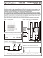
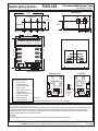
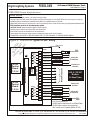
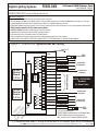
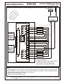
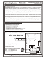
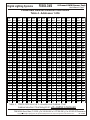
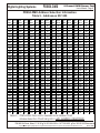
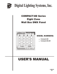
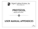
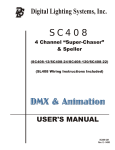
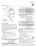
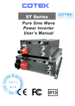
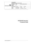
Digital Lighting Systems, Inc.
PD804-DMX
Eight Channel DMX Dimmer
and Switch Packs
PD804-DMX
S2 S1
1 2 3 4
S2 S1
5 6 7 8
USER'S MANUAL
PD804-DMX-UM
Rev. A - 04/02
Digital Lighting Systems
PD804-DMX
8-Channel DMX Dimmer Pack
User's Manual - Page 1
GENERAL DESCRIPTION
The PD804-DMX is an 8-channel DMX-512 compatible dimmer pack. It contains three printed circuit boards, the load driver module (LDM) and
two INT04 control modules. The LDM is equivalent to eight solid-state relays (SSR's) assembled on a single circuit board. Power is fed to the
PD804-DMX from two 20 Amp. breakers on the same electrical phase. Each breaker feeds four relays and each relay is rated for a maximum
output current of 4 amperes. The LDM is mounted at the bottom of the PD804-DMX's enclosure which also serves as a heat sink. The relays
are triggered by low-voltage signals generated by the INT04 modules. These signals are optically-isolated by the LDM circuitry from all line
voltage elements. A step-down 10 VAC- transformer on the LDM board supplies power to the INT04 modules.
DMX-512 control information is received by the INT04’s over a shielded twisted-pair cable. Several PD804-DMX and/or PD408-DMX dimmer
packs may be daisy-chained together using standard DMX cables with 5-pin XLR type connectors. Each PD804-DMX has two sets of address
selectors which may be set to unique addresses and will occupy the next four DMX control channels beginning with the address selected at the
front panel. When two or more units are set to the same address, their respective outputs work in unison, increasing the amount of load that can
be controlled by a single DMX channel. Each of the PD804-DMX outputs may be independently configured not to dim. In such case, a DMX
input value greater than 3 switches its respective output to 100%, else the output remains at 0%.
Figure 1 shows a functional block diagram of the PD804-DMX. Figure 2 shows a PD804-DMX and a PD408-DMX in a typical installation.
Figure 1 - PD804-DMX Functional Block Diagram
Table 1 - Terminals Definition
LDM Load Driver Module
DESCRIPTION
Output Of Solid-State Relay #1
Output Of Solid-State Relay #2
Output Of Solid-State Relay #3
Output Of Solid-State Relay #4
Output Of Solid-State Relay #5
Output Of Solid-State Relay #6
Output Of Solid-State Relay #7
Output Of Solid-State Relay #8
Hot Line Feed For Relays 1, 2, 3 & 4
Hot Line Feed For Relays 5, 6, 7 & 8
Neutral Bus Connections.
Triac2
Triac3
Electrical Characteristic
Terminal Maximum
Relay Load Current
1 to 8
4 Amps.
Input Current For Relays 1 & 2
H1
20 Amps.
Input Current For Relays 3 & 4
H2
20 Amps.
Input Voltage
H1-H2 240 VAC, 1-Phase.
INT04
Control
Board
Triac6
Triac7
Triac8
J3
N1
N2
N3
N4
N5
N6
N7
N8
5
6
7
8
H2
XLR Type DMX Connectors
4 #12 AWG Typical
To Distribution Panel
To Loads
PD804-DMX
NEUTRAL BUS
Triac5
Figure 2 - Typical Installation
DMX CONTROL
EQUIPMENT
3
4
Triac4
10 VAC
Transformer
INT04
Control
Board
Table 2 - Absolute Maximum Electrical Ratings
4 #12 AWG Typical
To Distribution Panel
H1
1
2
Triac1
SSR's OPTICAL ISOLATORS
NAME
1
2
3
4
5
6
7
8
H1
H2
N1-N8
To Loads
PD408-DMX
DMX-CC-LEN -Standard DMX Cable with 5-pin XLR Connectors
7588 NW 8th Street, Miami, Fl. 33126
Table 3 - XLR DMX Connectors Pin Assignment
Pin Function
Ground Shield
-DATA
+DATA
Empty
Empty
Pin No.
1
2
3
4
5
Tel: 305-264-8391 or 1-877-264-8391
Fax: 305-261-6637PD804-DMX-UM
Copyright 1999 Digital Lighting Systems, All rights Reserved Specifications are subject to change without notice. Printed in U.S.A.
Rev. A - 04/02
PD804-DMX
Digital Lighting Systems
8-Channel DMX Dimmer Pack
User's Manual - Page 2
Bottom View
8-1/4"
(210 mm)
IN
½" Conduit Ports
4-1/4"
(108 mm)
Top View
1
2
2"
(51 mm)
2-5/8"
(67 mm)
2"
(51 mm)
5
5
4
3
4
1
3
2
DMX Ports
2.600"
(66 mm)
2-3/16"
(56 mm)
OUT
1-1/2"
(38 mm)
2.000"
(51 mm)
1.500"
(38 mm)
5" (127 mm)
PD804-DMX Front Cover
PD804-DMX ( LDM) Load Driver Module
T8
T3
T7
T2
T6
T1
PD804
9 VAC
1
W1
INT04#1
3
2
W2
4
5
10
7
6
INT04#1
8
INT04#2
1 10
1
S2 S1
1 2 3 4
DMX XLR Connectors
LED OUTPUT
MONITORS
Components Side
INT04
S2 S1
1 2 3 4
Solder Side
INT04
3
2
4
3
2
1
4
1
5
5
S3
D
BC E
D
BC E
F 012
789A
789A
6
F 012
3456
S2
3456
INT04 Circuit Legend
1
Microprocessor.
2
Nonvolatile Memory.
3
Communications Chip.
4
Quartz Crystal.
5
Power Supply Capacitor.
6
Voltage Regulator.
7
Signal & Power Connector.
8
Output LED Monitors.
S1-2 Address Selectors.
S3
Address Expansion
INT04#2
ADDRESS SELECTORS
T5
LED
Transformer
10-5/8" (270 mm)
T4
PD804
9-3/4" (248 mm)
H1 1 2 3 4 N N N N N N N N 1 2 3 4 H2
8
S1
S3
7
Address
Expansion
Jumper (S3)
On Solder
Side
S1
S2
8
S3
6
7
Figure 3.
PD804-DMX Enclosure And Circuit Details
Enclosure Installation
Surface mount the dimmer pack in a well ventilated area where the ambient temperature does not exceed 90° F for full load operation. Allow
4" of side clearance for proper air circulation. Installation clearance shall meet local and/or NEC code requirements. Enclosures may be
attached to the wall or other mounting surface by holes in the heat sink flanges. Refer to the drawings above for the proper dimensions.
Conduit shall be pulled to the top of the dimmer packs.
NOTE
The PD804-DMX may create a slight buzzing noise and should not be located where this is objectionable.
7588 NW 8th Street, Miami, Fl. 33126
Tel: 305-264-8391 or 1-877-264-8391
Fax: 305-261-6637PD804-DMX-UM
Copyright 1999 Digital Lighting Systems, All rights Reserved Specifications are subject to change without notice. Printed in U.S.A.
Rev. A - 04/02
PD804-DMX
Digital Lighting Systems
8-Channel DMX Dimmer Pack
User's Manual - Page 3
PD804-DMX General Wiring Instructions
Wiring Notes
0 DO NOT EXCEED 480 W (4 Amps. ) per dimmer output @ 120VAC.
0 All wiring between the DMX control panel, dimmers, and other DMX equipment is low voltage (NEMA Class 2) and may be run with one
shielded twisted pair #18 AWG wire. Standard Industry DMX-512 compatible cables may be used.
0 PD804-DMX dimmer packs may be fed by one or two 20 A (maximum) branch circuits and may have up to eight separately dimmed loads.
0 Both breakers must be on the same power phase.
0 CAUTION: DO NOT attempt to parallel outputs to increase capacity.
0 Installations must conform to local and/or NEC code requirements.
0 Each load must have its own Neutral wire for full load operation.
0 All line voltage wires must have copper conductors of adequate Gauge with 90° C wire insulation.
0 POWER EACH LOAD DIRECTLY BEFORE CONNECTING IT TO THE PD804-DMX, TO ENSURE PROPER WIRING.
Earth Ground
LDM Load Driver Module
H1
1
2
Triac1
Triac2
Triac3
INT04
Control
Board
1,2,3,4
NEUTRAL BUS
10 VAC
Transformer
SSR's OPTICAL ISOLATORS
Triac4
INT04
Control
Board
1,2,3,4
Ground
3
4
N1
N2
N3
N4
N5
N6
N7
ON
HOT out # 1
HOT out # 2
HOT out # 3
HOT out # 4
LOAD #2
Triac6
Triac7
Triac8
5
6
7
8
H2
20 A
To Neutral Bus
in PD804 board
LOAD #3
LOAD #4
To Breaker Panel
Neutral Bus
2x20 A - 120 VAC
Breakers
On Same Phase
To Breaker Panel
Neutral Bus
N8
Triac5
Breaker
LOAD #1
Neutral From Loads
12 PD CAU
0 80 TIO
VA 4
- N
O C M DM
NL o X
Y de
ls
Figure 4. PD804-DMX Typical 120 VAC Wiring.
HOT out # 5
HOT out # 6
HOT out # 7
HOT out # 8
LOAD #5
LOAD #6
To Neutral Bus
in PD804 board
LOAD #7
LOAD #8
ON
Breaker
20 A
For Full Load Operation Use:
#12 AWG copper conductor wire for Line & Neutral Feeds.
#14 AWG copper conductors in/out to each load.
Max. Load per circuit : 4 Amperes (480W at 120 VAC).
7588 NW 8th Street, Miami, Fl. 33126
Tel: 305-264-8391 or 1-877-264-8391
Fax: 305-261-6637PD804-DMX-UM
Copyright 1999 Digital Lighting Systems, All rights Reserved Specifications are subject to change without notice. Printed in U.S.A.
Rev. A - 04/02
PD804-DMX
Digital Lighting Systems
8-Channel DMX Dimmer Pack
User's Manual - Page 4
PD804-DMX-220 General Wiring Instructions
Wiring Notes
0 DO NOT EXCEED 960 Watts (4 Amps) per dimmer output at 240 VAC.
0 All wiring between the DMX control panel, dimmers, and other DMX equipment is low voltage (NEMA Class 2) and may be run with one
shielded twisted pair #18 AWG wire. Standard Industry DMX-512 compatible cables may be used.
0 PD804-DMX dimmer packs may be fed by one or two 20 A (maximum) branch circuits and may have up to eight separately dimmed loads.
0 Both breakers must be on the same power phase.
0 CAUTION: DO NOT attempt to parallel outputs to increase capacity.
0 Installations must conform to local and/or NEC code requirements.
0 Each load must have its own Neutral wire for full load operation.
0 All line voltage wires must have copper conductors of adequate Gauge with 90° C wire insulation.
0 POWER EACH LOAD DIRECTLY BEFORE CONNECTING IT TO THE PD804-DMX, TO INSURE PROPER WIRING.
Figure 5. PD804-DMX Typical 220/240 VAC Wiring.
Earth Ground
LDM Load Driver Module
Triac2
Triac3
INT04
Control
Board
1,2,3,4
NEUTRAL BUS
10 VAC
Transformer
SSR's OPTICAL ISOLATORS
Triac4
3
4
N1
N2
N3
N4
N5
N6
N7
HOT out # 2
HOT out # 3
HOT out # 4
Triac5
5
6
Triac6
7
8
Triac8
H2
7588 NW 8th Street, Miami, Fl. 33126
Breaker
20 A
LOAD #1
LOAD #2
To Neutral Bus
in PD804 board
LOAD #3
LOAD #4
To Breaker Panel
Neutral Bus
2x20 A - 220/240 VAC
Breakers
On Same Phase
To Breaker Panel
Neutral Bus
N8
Triac7
22
C
0- PD AU
24 80 TI
0 4- O N
V
O AC DM
NL M X
Y
od
el
s
ON
HOT out # 1
Neutral From Loads
H1
1
2
Triac1
INT04
Control
Board
1,2,3,4
Ground
HOT out # 5
HOT out # 6
HOT out # 7
HOT out # 8
LOAD #5
LOAD #6
To Neutral Bus
in PD804 board
LOAD #7
LOAD #8
ON
Breaker
20 A
For Full Load Operation Use:
#12 AWG copper conductor wire for Line & Neutral Feeds.
#14 AWG copper conductors in/out to each load.
Max. Load per circuit : 4 Amperes (960W at 240VAC).
Tel: 305-264-8391 or 1-877-264-8391
Fax: 305-261-6637PD804-DMX-UM
Copyright 1999 Digital Lighting Systems, All rights Reserved Specifications are subject to change without notice. Printed in U.S.A.
Rev. A - 04/02
PD804-DMX
Digital Lighting Systems
8-Channel DMX Dimmer Pack
User's Manual - Page 5
Figure 6. PD804-DMX-24/12 Low Voltage Load and Power Wiring
P C
PD D80 AU
T
M 804 4-D ION
od -D M
el M X-2
s O X- 4
NL 12
Y
NEUTRAL
PRIMARY
SECONDARY
X1
LDM Load Driver Module
H1
1
2
Triac1
Triac2
Triac3
INT04
Control
Board
1,2,3,4
NEUTRAL BUS
10 VAC
Transformer
SSR's OPTICAL ISOLATORS
Triac4
INT04
Control
Board
1,2,3,4
ON
Electrical
Distribution Panel
3
4
N1
N2
N3
N4
N5
N6
N7
HOT out # 1
HOT out # 2
HOT out # 3
HOT out # 4
X4
LOAD #1
LOAD #2
LOAD #3
LOAD #4
N8
Triac5
Triac6
Triac7
Triac8
5
6
7
8
HOT out # 5
HOT out # 6
HOT out # 7
HOT out # 8
LOAD #5
LOAD #6
LOAD #7
LOAD #8
H2
For Full Load Operation Use:
#12 AWG copper conductor wire for Line & Neutral Feeds.
#14 AWG copper conductors in/out to each load.
Max. Load per circuit : 4 Amperes (96W at 24 VAC).
NOTES
1
2
3
4
5
With PD804-DMX-24 you may use a single 24 VAC-800 VA or better transformer or two separate 24 VAC-400 VA or better transformers.
With PD804-DMX-12 you may use a single 12 VAC-400 VA or better transformer or two separate 12 VAC-200 VA or better transformers.
Follow transformer's installation & wiring instructions from manufacturer.
Maximum Load Per Output: 48 Watts at 12 VAC.
Maximum Load Per Output: 96 watts at 24 VAC.
7588 NW 8th Street, Miami, Fl. 33126
Tel: 305-264-8391 or 1-877-264-8391
Fax: 305-261-6637PD804-DMX-UM
Copyright 1999 Digital Lighting Systems, All rights Reserved Specifications are subject to change without notice. Printed in U.S.A.
Rev. A - 04/02
PD804-DMX
Digital Lighting Systems
8-Channel DMX Dimmer Pack
User's Manual - Page6
DMX Address Setting
Up to 128 INT04-DMX boards (two in each PD804-DMX, one in each PD408-DMX) may be installed in any one system. Their DMX inputs
should be daisy-chained using standard DMX-512 cables. Different addresses ranging from 1 to 509 may be selected for each dimmer,
depending on which DMX channel(s) will be used to control it. Each INT04 uses four consecutive DMX bytes from the input stream beginning
at the address selected using rotary selectors S1, S2 and address expansion jumper S3. (See Figure 3 on page 2 for selectors location).
The PD804-DMX is shipped from the factory with jumpers S3 installed allowing a DMX address range between 1 and 256 to be selected by
S1 & S2 (See Table 4). For higher addresses ( 257-509) jumper S3 must be removed (See Table 5).
Non-Dim Output Setting
Any or all of the PD804-DMX outputs may be configured for non-dim (switch only) operation. This prevents inadvertent dimming, or damage,
of loads that cannot be dimmed, such as contactors, mechanical relays, motors, non-dim fluorescent, etc...
Since this procedure involves adding external wire jumpers to the INT4 board, it is preferable to have it performed by the factory, at time of
order. However, a qualified electronic technician can perform the procedure in the field when necessary. Figure 8 shows the location for
installing the non-dim (ND) jumpers.
The numbers shown next to the ND jumpers represent the corresponding output number of the PD804-DMX. Installing an ND jumper makes
the corresponding output non-dim (switch only). A DMX value greater than 3 turns a non-dim output to full intensity. A DMX value of 3 or less
turns it fully off.
PD804-DMX Installation Check List
BEFORE ENERGIZING THE PD804-DMX MAKE SURE:
0 Loads are tested before connecting to dimmers.
0 Breaker feed lines are on same electrical phase.
0 PD804-DMX has been properly grounded.
0 All line voltage screw terminals are properly tightened to prevent hot spots.
0 Low voltage data lines connections are properly insulated.
0 Low voltage data lines polarity is observed throughout the system.
Figure 7 - PD804-DMX Address & Mode Selection.
40TNI
INT04 Solder (Back) Side
ND1
ND2
ND3
3
2
10
ND4
1
5
5
1
Non-Dim Jumpers ND1-ND4
Installed
Removed
Output Is Non-Dim (Switch Only)
Normal Dimmer Output.
1S
Unit is shipped without ND jumpers.
Address Expansion Jumper (S3)
Installed
Removed
4
(S2,S1) Address Range: 1-256
(S2,S1) Address Range: 257-509
Unit is shipped with S3 Installed.
7588 NW 8th Street, Miami, Fl. 33126
2S
8
S3
6
7
Tel: 305-264-8391 or 1-877-264-8391
Fax: 305-261-6637PD804-DMX-UM
Copyright 1999 Digital Lighting Systems, All rights Reserved Specifications are subject to change without notice. Printed in U.S.A.
Rev. A - 04/02
PD804-DMX
Digital Lighting Systems
8-Channel DMX Dimmer Pack
User's Manual - Page 7
PD804-DMX Address Selection Information
Table 4 - Addresses 1-256
Cha.
Select
Cha.
Select
Cha.
Select
Cha.
Select
Cha.
Select
Cha.
Select
Cha.
Select
Cha.
Select
Addr.
S2 S1
Addr.
S2 S1
Addr.
S2 S1
Addr.
S2 S1
Addr.
S2 S1
Addr.
S2 S1
Addr.
S2 S1
Addr.
S2 S1
1
00
33
20
65
40
97
60
129
80
161
A0
193
C0
225
E0
2
01
34
21
66
41
98
61
130
81
162
A1
194
C1
226
E1
3
02
35
22
67
42
99
62
131
82
163
A2
195
C2
227
E2
4
03
36
23
68
43
100
63
132
83
164
A3
196
C3
228
E3
5
04
37
24
69
44
101
64
133
84
165
A4
197
C4
229
E4
6
05
38
25
70
45
102
65
134
85
166
A5
198
C5
230
E5
7
06
39
26
71
46
103
66
135
86
167
A6
199
C6
231
E6
8
07
40
27
72
47
104
67
136
87
168
A7
200
C7
232
E7
9
08
41
28
73
48
105
68
137
88
169
A8
201
C8
233
E8
10
09
42
29
74
49
106
69
138
89
170
A9
202
C9
234
E9
11
0A
43
2A
75
4A
107
6A
139
8A
171
AA
203
CA
235
EA
12
0B
44
2B
76
4B
108
6B
140
8B
172
AB
204
CB
236
EB
13
0C
45
2C
77
4C
109
6C
141
8C
173
AC
205
CC
237
EC
14
0D
46
2D
78
4D
110
6D
142
8D
174
AD
206
CD
238
ED
15
0E
47
2E
79
4E
111
6E
143
8E
175
AE
207
CE
239
EE
16
0F
48
2F
80
4F
112
6F
144
8F
176
AF
208
CF
240
EF
17
10
49
30
81
50
113
70
145
90
177
B0
209
D0
241
F0
18
11
50
31
82
51
114
71
146
91
178
B1
210
D1
242
F1
19
12
51
32
83
52
115
72
147
92
179
B2
211
D2
243
F2
20
13
52
33
84
53
116
73
148
93
180
B3
212
D3
244
F3
21
14
53
34
85
54
117
74
149
94
181
B4
213
D4
245
F4
22
15
54
35
86
55
118
75
150
95
182
B5
214
D5
246
F5
23
16
55
36
87
56
119
76
151
96
183
B6
215
D6
247
F6
24
17
56
37
88
57
120
77
152
97
184
B7
216
D7
248
F7
25
18
57
38
89
58
121
78
153
98
185
B8
217
D8
249
F8
26
19
58
39
90
59
122
79
154
99
186
B9
218
D9
250
F9
27
1A
59
3A
91
5A
123
7A
155
9A
187
BA
219
DA
251
FA
28
1B
60
3B
92
5B
124
7B
156
9B
188
BB
220
DB
252
FB
29
1C
61
3C
93
5C
125
7C
157
9C
189
BC
221
DC
253
FC
30
1D
62
3D
94
5D
126
7D
158
9D
190
BD
222
DD
254
FD
31
1E
63
3E
95
5E
127
7E
159
9E
191
BE
223
DE
255
FE
32
1F
64
3F
96
5F
128
7F
160
9F
192
BF
224
DF
256
FF
Table 4 - PD804-DMX Decimal to Hexadecimal Address Chart.
Address Selection Chart Using S2-S1 with JUMPER 3 INSTALLED
7588 NW 8th Street, Miami, Fl. 33126
Tel: 305-264-8391 or 1-877-264-8391
Fax: 305-261-6637 PD804-DMX-UM
Copyright 1999 Digital Lighting Systems, All rights Reserved Specifications are subject to change without notice. Printed in U.S.A.
Rev. A - 04/02
PD804-DMX
Digital Lighting Systems
8-Channel DMX Dimmer Pack
User's Manual - Page 8
PD804-DMX Address Selection Information
Table 5 - Addresses 257-509
Cha.
Select
Cha.
Select
Cha.
Select
Cha.
Select
Cha.
Select
Cha.
Select
Cha.
Select
Cha.
Select
Addr.
S2 S1
Addr.
S2 S1
Addr.
S2 S1
Addr.
S2 S1
Addr.
S2 S1
Addr.
S2 S1
Addr.
S2 S1
Addr.
S2 S1
257
00
289
20
321
40
353
60
385
80
417
A0
449
C0
481
E0
258
01
290
21
322
41
354
61
386
81
418
A1
450
C1
482
E1
259
02
291
22
323
42
355
62
387
82
419
A2
451
C2
483
E2
260
03
292
23
324
43
356
63
388
83
420
A3
452
C3
484
E3
261
04
293
24
325
44
357
64
389
84
421
A4
453
C4
485
E4
262
05
294
25
326
45
358
65
390
85
422
A5
454
C5
486
E5
263
06
295
26
327
46
359
66
391
86
423
A6
455
C6
487
E6
264
07
296
27
328
47
360
67
392
87
424
A7
456
C7
488
E7
265
08
297
28
329
48
361
68
393
88
425
A8
457
C8
489
E8
266
09
298
29
330
49
362
69
394
89
426
A9
458
C9
490
E9
267
0A
299
2A
331
4A
363
6A
395
8A
427
AA
459
CA
491
EA
268
0B
300
2B
332
4B
364
6B
396
8B
428
AB
460
CB
492
EB
269
0C
301
2C
333
4C
365
6C
397
8C
429
AC
461
CC
493
EC
270
0D
302
2D
334
4D
366
6D
398
8D
430
AD
462
CD
494
ED
271
0E
303
2E
335
4E
367
6E
399
8E
431
AE
463
CE
495
EE
272
0F
304
2F
336
4F
368
6F
400
8F
432
AF
464
CF
496
EF
273
10
305
30
337
50
369
70
401
90
433
B0
465
D0
497
F0
274
11
306
31
338
51
370
71
402
91
434
B1
466
D1
498
F1
275
12
307
32
339
52
371
72
403
92
435
B2
467
D2
499
F2
276
13
308
33
340
53
372
73
404
93
436
B3
468
D3
500
F3
277
14
309
34
341
54
373
74
405
94
437
B4
469
D4
501
F4
278
15
310
35
342
55
374
75
406
95
438
B5
470
D5
502
F5
279
16
311
36
343
56
375
76
407
96
439
B6
471
D6
503
F6
280
17
312
37
344
57
376
77
408
97
440
B7
472
D7
504
F7
281
18
313
38
345
58
377
78
409
98
441
B8
473
D8
505
F8
282
19
314
39
346
59
378
79
410
99
442
B9
474
D9
506
F9
283
1A
315
3A
347
5A
379
7A
411
9A
443
BA
475
DA
507
FA
284
1B
316
3B
348
5B
380
7B
412
9B
444
BB
476
DB
508
FB
285
1C
317
3C
349
5C
381
7C
413
9C
445
BC
477
DC
509
FC
286
1D
318
3D
350
5D
382
7D
414
9D
446
BD
478
DD
510
N/A
287
1E
319
3E
351
5E
383
7E
415
9E
447
BE
479
DE
511
N/A
288
1F
320
3F
352
5F
384
7F
416
9F
448
BF
480
DF
512
N/A
Table 5 - PD804-DMX Decimal to Hexadecimal Address Chart.
Address Selection Chart Using S2-S1 with JUMPER 3 REMOVED
7588 NW 8th Street, Miami, Fl. 33126
Tel: 305-264-8391 or 1-877-264-8391
Fax: 305-261-6637PD804-DMX-UM
Copyright 1999 Digital Lighting Systems, All rights Reserved Specifications are subject to change without notice. Printed in U.S.A.
Rev. A - 04/02
LIMITED WARRANTY
Digital Lighting Systems, warrants to the purchaser that its
products have been carefully manufactured and inspected and
are warranted to be free from defects of workmanship and
materials when used as intended. Any abuse or misuse contrary
to normal operation shall void this warranty.
Upon request, replacement unit(s) will be shipped as soon as
available. Unless immediate shipment of replacement
merchandise is requested, Digital Lighting Systems will not
ship replacement merchandise until defective merchandise is
received, inspected, and determined to be defective.
Digital Lighting Systems' obligation under this warranty shall be
limited to replacement or repair of any units as shall within two
years of date of invoice from Digital Lighting Systems, prove
defective; and Digital Lighting Systems shall not be liable for
any other damages, whether direct or consequential. The
implied warranties of merchantability and fitness for a
particular purpose are limited to the duration of the
expressed warranty. Some states do not allow the exclusion of
the limitation of incidental or consequential damages, so the
above limitation or exclusion may not apply to you. This
warranty gives you specific legal rights, you may also have other
legal rights which vary from state to state.
No labor charges in connection with warranty problems will
be reimbursed by Digital Lighting Systems without prior
written approval from the factory.
Defective merchandise may be returned to Digital Lighting
Systems, prepaid, after prior notification has been given and
approval obtained for the return. To obtain prior approval for the
return of the defective items, contact your local Digital Lighting
Systems distributor, representative, or:
Digital Lighting Systems, Inc.
Attn: Customer Service Department
7588 NW 8th Street
Miami, FL 33126
(305) 264-8391
Digital Lighting Systems distributors and representatives have
no authority to change this warranty without written permission.
Digital Lighting Systems reserves the right to determine the
best method of correcting warranty problems.
Digital Lighting Systems, Inc.
7588 NW 8th Street
Miami, FL 33126
www.digitallighting.com
Tel
Fax
e-m
305-264-8391
305-261-6637
[email protected]
Printed in U.S.A.
April 2002