1
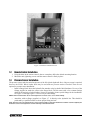
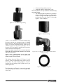
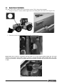
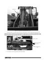
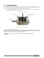
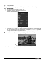
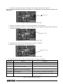
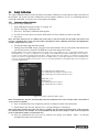
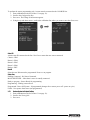
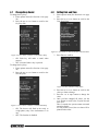
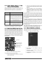
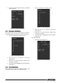
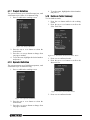
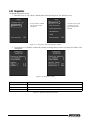
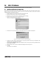
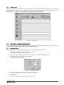
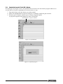
WLS-1
Wheel Loader Scale
Version 2.0
Installation & User Manual
To be the best by every measure
101063
Contents
Introduction.............................................................................................................................................. 1
1.0
Installation ................................................................................................................................... 1
1.1
1.2
1.3
1.4
1.5
2.0
Indicator Installation . . . . . . . . . . . . . . . . . . . . . . . . . . . . . . . . . . . . . . . . . . . . . . . . . . . . . . . . . . . . . .
Remote Control Installation. . . . . . . . . . . . . . . . . . . . . . . . . . . . . . . . . . . . . . . . . . . . . . . . . . . . . . . . .
Pressure Sensor Installation . . . . . . . . . . . . . . . . . . . . . . . . . . . . . . . . . . . . . . . . . . . . . . . . . . . . . . . .
Angle Sensor Installation . . . . . . . . . . . . . . . . . . . . . . . . . . . . . . . . . . . . . . . . . . . . . . . . . . . . . . . . . .
Junction Box Installation. . . . . . . . . . . . . . . . . . . . . . . . . . . . . . . . . . . . . . . . . . . . . . . . . . . . . . . . . . .
1
3
3
6
8
Display Indications and Button Functions ................................................................................... 9
2.1 Indicator Display . . . . . . . . . . . . . . . . . . . . . . . . . . . . . . . . . . . . . . . . . . . . . . . . . . . . . . . . . . . . . . . . . 9
2.2 Indicator Buttons . . . . . . . . . . . . . . . . . . . . . . . . . . . . . . . . . . . . . . . . . . . . . . . . . . . . . . . . . . . . . . . 10
2.3 Remote Control . . . . . . . . . . . . . . . . . . . . . . . . . . . . . . . . . . . . . . . . . . . . . . . . . . . . . . . . . . . . . . . . 11
3.0
Calibration ................................................................................................................................. 12
3.1 Entering Calibration Mode . . . . . . . . . . . . . . . . . . . . . . . . . . . . . . . . . . . . . . . . . . . . . . . . . . . . . . . . 12
3.2 Area Ratio . . . . . . . . . . . . . . . . . . . . . . . . . . . . . . . . . . . . . . . . . . . . . . . . . . . . . . . . . . . . . . . . . . . . 13
3.3 Angle Calibration . . . . . . . . . . . . . . . . . . . . . . . . . . . . . . . . . . . . . . . . . . . . . . . . . . . . . . . . . . . . . . . 14
3.3.1
Calibration Procedure . . . . . . . . . . . . . . . . . . . . . . . . . . . . . . . . . . . . . . . . . . . . . . . . . . . . . . . . . . . . . 14
3.4 Empty Calibration . . . . . . . . . . . . . . . . . . . . . . . . . . . . . . . . . . . . . . . . . . . . . . . . . . . . . . . . . . . . . . . 16
3.4.1
Performing an Empty Calibration . . . . . . . . . . . . . . . . . . . . . . . . . . . . . . . . . . . . . . . . . . . . . . . . . . . . . 16
3.5 Loaded Calibration . . . . . . . . . . . . . . . . . . . . . . . . . . . . . . . . . . . . . . . . . . . . . . . . . . . . . . . . . . . . . . 17
3.6 Known Load. . . . . . . . . . . . . . . . . . . . . . . . . . . . . . . . . . . . . . . . . . . . . . . . . . . . . . . . . . . . . . . . . . . 18
3.7 Configuration Menu . . . . . . . . . . . . . . . . . . . . . . . . . . . . . . . . . . . . . . . . . . . . . . . . . . . . . . . . . . . . . 18
3.7.1
3.7.2
Program Angular Sensor Id . . . . . . . . . . . . . . . . . . . . . . . . . . . . . . . . . . . . . . . . . . . . . . . . . . . . . . . . . 19
Restore System to Original Setting . . . . . . . . . . . . . . . . . . . . . . . . . . . . . . . . . . . . . . . . . . . . . . . . . . . 20
3.8 Parameters. . . . . . . . . . . . . . . . . . . . . . . . . . . . . . . . . . . . . . . . . . . . . . . . . . . . . . . . . . . . . . . . . . . . 21
3.8.1
4.0
Setting and Saving Parameters . . . . . . . . . . . . . . . . . . . . . . . . . . . . . . . . . . . . . . . . . . . . . . . . . . . . . . 22
Operation.................................................................................................................................... 23
4.1 Making a Weighment . . . . . . . . . . . . . . . . . . . . . . . . . . . . . . . . . . . . . . . . . . . . . . . . . . . . . . . . . . . .
4.2 Setting a New Tare. . . . . . . . . . . . . . . . . . . . . . . . . . . . . . . . . . . . . . . . . . . . . . . . . . . . . . . . . . . . . .
4.3 Disabling the Weighing Feature . . . . . . . . . . . . . . . . . . . . . . . . . . . . . . . . . . . . . . . . . . . . . . . . . . . .
4.4 Entering Options Menu. . . . . . . . . . . . . . . . . . . . . . . . . . . . . . . . . . . . . . . . . . . . . . . . . . . . . . . . . . .
4.5 Change Display Brightness. . . . . . . . . . . . . . . . . . . . . . . . . . . . . . . . . . . . . . . . . . . . . . . . . . . . . . . .
4.6 Change Display Colors . . . . . . . . . . . . . . . . . . . . . . . . . . . . . . . . . . . . . . . . . . . . . . . . . . . . . . . . . . .
4.7 Change Beep Sound . . . . . . . . . . . . . . . . . . . . . . . . . . . . . . . . . . . . . . . . . . . . . . . . . . . . . . . . . . . .
4.8 Setting Date and Time . . . . . . . . . . . . . . . . . . . . . . . . . . . . . . . . . . . . . . . . . . . . . . . . . . . . . . . . . . .
4.9 Configure Alarm Clock . . . . . . . . . . . . . . . . . . . . . . . . . . . . . . . . . . . . . . . . . . . . . . . . . . . . . . . . . . .
4.10 Count Down Function . . . . . . . . . . . . . . . . . . . . . . . . . . . . . . . . . . . . . . . . . . . . . . . . . . . . . . . . . . .
4.11 Select Machine . . . . . . . . . . . . . . . . . . . . . . . . . . . . . . . . . . . . . . . . . . . . . . . . . . . . . . . . . . . . . . . .
4.12 Partial Zeroing, Partial x 2, Total, Totals, and Tare Procedure . . . . . . . . . . . . . . . . . . . . . . . . . . . . .
4.13 Multi-Product/Multi-Truck Function . . . . . . . . . . . . . . . . . . . . . . . . . . . . . . . . . . . . . . . . . . . . . . . . .
4.14 Material Definition and Density . . . . . . . . . . . . . . . . . . . . . . . . . . . . . . . . . . . . . . . . . . . . . . . . . . . .
4.15 Customer Definition . . . . . . . . . . . . . . . . . . . . . . . . . . . . . . . . . . . . . . . . . . . . . . . . . . . . . . . . . . . .
23
23
23
24
24
24
25
25
26
26
26
27
27
27
28
Technical training seminars are available through Rice Lake Weighing Systems.
Technical training seminars are available through Rice Lake Weighing Systems.
Course
datescan
canbe
beviewed
viewed
www.ricelake.com/training
Coursedescriptions
descriptions and
and dates
at at
www.ricelake.com/training
ororobtained
by
calling
715-234-9171
and
asking
for the
training
department.
obtained by calling 715-234-9171 and asking for the
training
department.
© 2010 Rice Lake Weighing Systems. All rights reserved. Printed in the United States of America.
Specifications subject to change without notice.
Rice Lake Weighing Systems is an ISO 9001 registered company.
Version 2.0, November 2010
i
4.16 Truck Definition . . . . . . . . . . . . . . . . . . . . . . . . . . . . . . . . . . . . . . . . . . . . . . . . . . . . . . . . . . . . . . .
4.17 Project Definition . . . . . . . . . . . . . . . . . . . . . . . . . . . . . . . . . . . . . . . . . . . . . . . . . . . . . . . . . . . . . .
4.18 Operator Definition . . . . . . . . . . . . . . . . . . . . . . . . . . . . . . . . . . . . . . . . . . . . . . . . . . . . . . . . . . . . .
4.19 Database Totals Summary . . . . . . . . . . . . . . . . . . . . . . . . . . . . . . . . . . . . . . . . . . . . . . . . . . . . . . .
4.20 Printer Function . . . . . . . . . . . . . . . . . . . . . . . . . . . . . . . . . . . . . . . . . . . . . . . . . . . . . . . . . . . . . . .
4.20.1
4.20.2
4.20.3
4.20.4
4.20.5
Printing the Ticket . . . . . . . . . . . . . . . . . . . . . . . . . . . . . . . . . . . . . . . . . . . . . . . . . . . . . . . . . . . . . . . .
Printer Options . . . . . . . . . . . . . . . . . . . . . . . . . . . . . . . . . . . . . . . . . . . . . . . . . . . . . . . . . . . . . . . . . .
Zero or Change the Ticket Number . . . . . . . . . . . . . . . . . . . . . . . . . . . . . . . . . . . . . . . . . . . . . . . . . . .
Setting a Print Header. . . . . . . . . . . . . . . . . . . . . . . . . . . . . . . . . . . . . . . . . . . . . . . . . . . . . . . . . . . . .
Remote Control Printing . . . . . . . . . . . . . . . . . . . . . . . . . . . . . . . . . . . . . . . . . . . . . . . . . . . . . . . . . . .
28
29
29
29
30
30
30
31
31
31
4.21 Correction Function . . . . . . . . . . . . . . . . . . . . . . . . . . . . . . . . . . . . . . . . . . . . . . . . . . . . . . . . . . . . 31
4.22 Alarms . . . . . . . . . . . . . . . . . . . . . . . . . . . . . . . . . . . . . . . . . . . . . . . . . . . . . . . . . . . . . . . . . . . . . . 31
4.23 Diagnostics . . . . . . . . . . . . . . . . . . . . . . . . . . . . . . . . . . . . . . . . . . . . . . . . . . . . . . . . . . . . . . . . . . 32
5.0
WLS-1 PC Software.................................................................................................................... 33
5.1 Installing and Obtaining a License Code . . . . . . . . . . . . . . . . . . . . . . . . . . . . . . . . . . . . . . . . . . . . . 33
5.2 Databases . . . . . . . . . . . . . . . . . . . . . . . . . . . . . . . . . . . . . . . . . . . . . . . . . . . . . . . . . . . . . . . . . . . . 34
5.2.1
5.2.2
Entering Database Information . . . . . . . . . . . . . . . . . . . . . . . . . . . . . . . . . . . . . . . . . . . . . . . . . . . . . . 34
Database Totals . . . . . . . . . . . . . . . . . . . . . . . . . . . . . . . . . . . . . . . . . . . . . . . . . . . . . . . . . . . . . . . . . 35
5.3 Uploading and Downloading Data . . . . . . . . . . . . . . . . . . . . . . . . . . . . . . . . . . . . . . . . . . . . . . . . . . 35
5.3.1
5.3.2
5.3.3
Connection Options . . . . . . . . . . . . . . . . . . . . . . . . . . . . . . . . . . . . . . . . . . . . . . . . . . . . . . . . . . . . . . 35
Uploading Data from the PC to the WLS-1 Indicator . . . . . . . . . . . . . . . . . . . . . . . . . . . . . . . . . . . . . . 36
Downloading Data from the WLS-1 Indicator to the PC. . . . . . . . . . . . . . . . . . . . . . . . . . . . . . . . . . . . 37
5.4 File Management . . . . . . . . . . . . . . . . . . . . . . . . . . . . . . . . . . . . . . . . . . . . . . . . . . . . . . . . . . . . . . . 37
5.4.1
Saving and Opening Files . . . . . . . . . . . . . . . . . . . . . . . . . . . . . . . . . . . . . . . . . . . . . . . . . . . . . . . . . . 37
5.5 Data Logger . . . . . . . . . . . . . . . . . . . . . . . . . . . . . . . . . . . . . . . . . . . . . . . . . . . . . . . . . . . . . . . . . . 38
6.0
Printer ........................................................................................................................................ 39
6.1 Specifications . . . . . . . . . . . . . . . . . . . . . . . . . . . . . . . . . . . . . . . . . . . . . . . . . . . . . . . . . . . . . . . . . 40
7.0
Appendix .................................................................................................................................... 41
7.1 System Diagram . . . . . . . . . . . . . . . . . . . . . . . . . . . . . . . . . . . . . . . . . . . . . . . . . . . . . . . . . . . . . . . 41
WLS-1 Limited Warranty ........................................................................................................................ 43
For More Information ............................................................................................................................. 44
Rice Lake continually offers web-based video training on a growing selection
of product-related topics at no cost. Visit www.ricelake.com/webinars.
ii
WLS-1 Wheel Loader Scale
Introduction
This manual is intended for use by technicians
responsible for installing and servicing the WLS-1
Wheel Loader Scale, color indicator version.
Authorized distributors and their employees
can view or download this manual from the
Rice Lake Weighing Systems distributor site
at www.ricelake.com.
Unpack the contents of the shipment your system
arrived in and verify the contents are correct, using the
packing slip. Check for damage that could have
occurred during shipment, and report any
discrepancies immediately.
Before installing, ensure you have the following:
• Welder
• Mechanical and electrical tools
• Set of assorted wrenches
• Set of assorted screwdrivers
• Grinder
• Voltmeter
• Assorted hydraulic fittings
1.0
If washing the machine with a
high-pressure power washer, you
must protect all system components
from direct spraying to avoid damage.
Warning
Safety Considerations
Before installing the WLS-1 Wheel Loader Scale,
take the following measures to ensure your safety:
• Lower the wheel loader’s bucket completely
to the ground
• Remove keys from the ignition
Hydraulic Parts
Discharge all pressure from the hydraulic circuit
before disconnecting or removing any plumbing,
connector, or relative component. Always make
certain that all moving parts have been locked and
check for any residual pressure when disconnecting
any hydraulic plumbing. Always let the bucket or
other similar parts down to ground-level before
carrying out any work on the machine.
Before working on any hydraulic lines, they must be
removed for modification, then properly cleaned
before re-installation.
Installation
When installing the components, use the appropriate brackets supplied. These can be mounted inside the cab
onto the cab structure. It is recommended that you consult the machine’s operator to ensure the indicator and
remote control are mounted in convenient locations based on his/her needs. Make sure the components do not
restrict the operator’s vision or interfere with bodily movements.
Do not attach the brackets to the dashboard or other non-metallic surface. Prior to altering the
Warning cab structure, customer approval should be attained due to EROPS and ROPS certifications.
1.1
Indicator Installation
1. Use the bracket as a template to drill holes. Then, mount the bracket. Or, use the suction cup mount.
2. Fasten screws holding the bracket in place. The bracket can now accept the indicator.
3. Loosen the bracket handle shown in Figure 1-1, find the desired angle, and tighten the handle.
Bracket handle
Figure 1-1. Bracket screwed in place (left); Suction cup bracket (right)
WLS-1 Wheel Loader Scale - Installation
1
Display
Setting and
Operating Keys
Signal lamps
indicate when
the maximum
load set has
been reached
Menu Keys
Figure 1-2. Indicator Front
On/Off Switch
Connection to Printer or PC
Connection to the
Junction Box
Connection to Auxiliary
External Device
Figure 1-3. Indicator Back
2
WLS-1 Wheel Loader Scale
Figure 1-4. Indicator Mounted in Cab
1.2
Remote Control Installation
1. Using the holes in the remote control’s base as a template, drill at the desired mounting location.
2. Mount the unit, tightening screws until the remote control is firmly in place.
1.3
Pressure Sensor Installation
The pressure sensor reads the main line pressure of the lift cylinder (hydraulic line). Only one sensor is required;
however, the WLS-1 Wheel Loader Scale may be used with two pressure sensors if needed. There are two
options for pressure sensor installation:
• Install a flange block where the hydraulic line attaches to the hydraulic fluid distributor. Use one of the
fittings supplied to attach the sensor to the flange block. The kit comes with a few common fittings
which fit the majority of wheel loaders. It may be required to locate special fittings for the installation.
See Figure 1-5 through Figure 1-8 for a list of provided fittings.
NOTE: Some manufacturers do not use flange blocks. In these cases, use a swivel T-fitting.
•
Attach the weld-on flange (supplied, see Figure 1-7 4) directly to the hydraulic line. This should be
performed by a qualified welder to ensure proper fitting and seal.
Note: The best source for flange blocks is the local heel loader or skid steer dealer that sold the machine originally. An
alternative source for flange blocks is www.mainmfg.com/mainhome.html.
WLS-1 Wheel Loader Scale - Installation
3
1. Select the fitting which works best.
2. Attach the fitting to the hydraulic valve.
Note: The hydraulic line may need to be removed if using
the weld-on flange.
3. The fitting should be mounted in a position to
allow it to self-bleed with gravity. If possible,
mount at an angle rather than perpendicular to
the hydraulic line. (See Figure 1-10 through
Figure 1-12 for examples).
Figure 1-5. 1/4" BSPP Straight Fitting
Figure 1-7. Weld-on Flange
Figure 1-6. 1/4" NPT Male to 1/4" Female Straight Fitting
Pressure sensors are equipped with 1/4" BSPP
threads; therefore, the fittings shown in Figure 1-5 and
Figure 1-6 can be connected directly to the sensor
with the copper o-ring seal (see Figure 1-9) in
between. This seal must be installed on all pressure
sensors to ensure an air-tight seal.
Notes: The copper o-ring seal has a smooth side and a
rough side. The seal should be installed so the smooth
side touches the sensor.
Figure 1-8. 1/4" NPT male to 1/4" BSPP Female Swivel
90-Degree Fitting
There is also a rubber gasket on the sensor (see
Figure 1-12 on page 5). Keep this in a safe place until
ready to install, as it falls off easily.
The fittings shown in Figure 1-5, Figure 1-6 and
Figure 1-8 can be connected directly to the valve of
the machine. The weld-on fitting (Figure 1-7) can be
used on the steel tubing of the cylinder line if you
cannot tap the line.
The fitting shown in Figure 1-8 cannot be connected
directly to the pressure sensor due to a 37-degree flare
swivel end.
4
WLS-1 Wheel Loader Scale
Figure 1-9. Copper O-Ring Seal
Figure 1-10. Flange Welded to Hydraulic Line at Desired Angle
Figure 1-11. Sensor Mounted at Non-Recommended Angle
Rubber gasket
Figure 1-12. Sensor Mounted at Recommended Angle; Rubber Gasket Highlighted
4. Place the copper o-ring between the sensor and fitting (with the smooth side towards the sensor) and
tighten the sensor with a crescent wrench.
5. Once the sensor is mounted, the hydraulic line can be bled.
6. After starting the machine, partially loosen the sensor.
7. Wait until fluid leaks out without any air bubbles before tightening it down.
8. Route wire back to where the j-box will be installed (preferably the cab). Route along a stationary area;
tying to existing electrical lines is recommended (see).
9. Tie off excess wire in an open area of the wheel loader.
10. Check for leaks again after running the machine for a short period of time.
WLS-1 Wheel Loader Scale - Installation
5
1.4
Angle Sensor Installation
The angle sensor can be installed in lieu of proximity sensors. This is the preferred method.
1. Using two to three 1" beads, weld the angle sensor’s mounting plate to the inside of the support arm.
Mounting plate
Figure 1-13. Weld The Angle Sensor Mounting Plate Onto The Support Arm
2. Fasten the sensor housing and angle sensor to the mounting plate.
Figure 1-14. Attached sensor on plate
NOTE: Angle sensor on boom is mounted so that the cable is at 3 o’clock (cable pointed toward cab). This cable
connects to the chassis sensor. Angle sensor on chassis is mounted with both cables pointed down. This cable
connects to junction box. See Figure 1-16. Both angle sensors should be mounted on the same side of the machine (left
or right).
Figure 1-15. Install the sensor on the plate as shown
6
WLS-1 Wheel Loader Scale
Angle Sensor
Figure 1-16. Angle Sensor Installed On Support Arm.
3. Route the sensor’s wire back to the area where the junction box will be installed (preferably the cab).
Notes: Ensure there is enough slack in the wire to allow the support arm to rise fully without over-tightening the wire.
Route along a stationary area of the wheel loader. Figure 1-17 shows the pressure sensor and angle sensor wires routed
between a stationary cylinder and existing electrical line; this provides optimal protection.
stationary cylinder
pressure and angle
sensor wires
existing electrical
line
Figure 1-17. Wires Routed Along Existing Electrical Line.
4. Tie off excess wire in an open area of the wheel loader.
WLS-1 Wheel Loader Scale - Installation
7
1.5
Junction Box Installation
Before you begin wiring the junction box, select an area where it can sit unobstructed. Beneath the operator’s
seat is typically a good choice. Avoid areas where it may be stepped on or have its connections pulled. See
Figure 7-1, “WLS-1 System Diagram,” on page 41 for a detailed system diagram.
1. Connect the remote control, pressure sensor wire, angle sensor wire, indicator cable, and power supply to
the junction box’s inputs, as shown in Figure 1-18.
High chamber pressure transducer
Low chamber
pressure transducer
Proximity sensors
Display cable
Power supply
Angle sensors
Figure 1-18. Junction Box Connections
2. Connect power to the junction box.
NOTE: The system comes with a power cable, which has a (brown/white) +VB (power 10-30 vdc input), (yellow/green)
-VB (ground), and shield cable (ground). It is recommended that the power supply AND ground be connected to the
battery, or to an unused circuit breaker to avoid any issues with the system.
+VB connects to + (positive) side of battery and -VB to negative battery terminal.
8
WLS-1 Wheel Loader Scale
2.0
2.1
Display Indications and Button Functions
Indicator Display
Rice Lake Weighing Systems’ WLS1 indicator is capable of displaying multiple readouts depending on the
function. Refer to Figure 2-1 for an explanation of these readouts.
Figure 2-1. Indicator Display Readouts
WLS-1 Wheel Loader Scale - Display Indications and Button Functions
9
2.2
Indicator Buttons
Indicator buttons are your interface for communicating with the indicator.
8, 9, 10
1
2
3
4
5
6
7
Figure 2-2. Indicator Keypad Buttons
Number referenced in
Figure 2-2
Button
Function
1
Short press: option menu
Long press: diagnostic and calibration
2
Exit (back to previous menu page).
3
Enable/disable the weighing system
4
Tare
5
Printer page and total visualization
6
Zeroing page
7
Enter in the menu indicated by the above icon
8
Confirm the selected function / enter in the selected menu
9
Cursor up/down in the text menu
10
Value decrease/increase in text menu
Table 2-1. Keypad Button Functions
10
WLS-1 Wheel Loader Scale
2.3
Remote Control
The remote control has three switches numbered 1 through 3 as shown in Figure 2-3. It also includes an audible
alarm/horn of operation, reference number 4, which is active in the measurement phase. See Table 2-2 for a
description of each remote control function.
4
5
1
3
2
Figure 2-3. Remote Control
Number Referenced in Figure 2-3
Function
1
Print the ticket
2
Quick press: Partial value (last bucket) zeroing
Press and hold for 5 seconds: Total value (truck) zeroing
3
Quick press:
• If OnDemandSum function is OFF: Enable or disable the weighing system
• If OnDemandSum function is ON: Add the partial weigh to the total weigh
Press and hold for 5 seconds: Will print and zero the total
4
Acoustic sound during operation
5
Connecting cable
Table 2-2. Remote Control Functions
WLS-1 Wheel Loader Scale - Display Indications and Button Functions
11
3.0
Calibration
To calibrate the WLS-1, you must enter calibration
mode. This allows you to alter system settings.
NOTE: Angle calibration must be performed prior to
loaded calibration.
3.1
Entering Calibration Mode
1. Press and hold the Diagnostic and
Calibration button on the indicator’s
keypad.
The display changes to the system menu,
shown in Figure 3-1.
Figure 3-2. Access Code Entered in Display
NOTE: Use the < and > selections to navigate the cursor
and correct any typing errors.
4. Once 04482 is present on the display press
Enter.
Figure 3-1. System Menu
2. Press the Enter button.
3. Using the Up, Down, Left, or Right buttons,
scroll to the each number of the access code
and press the Enter button.
The default access code is 04482. You must
enter this code to enter the calibration area of
the system.
Figure 3-3. Press Enter to Proceed to Calibration Menu
NOTE: If you are calibrating a second machine using the
same indicator see Section 4.11 on page 26.
12
WLS-1 Wheel Loader Scale
3.2
Area Ratio
The Area Ratio is the ratio between the cylinder’s
chambers where the pressure transducers are installed.
This type of calibration is used only in systems with
two pressure transducers are installed.
1. Enter calibration mode (See Section 3.1 on
page 12).
2. Scroll down to the Area Ratio line and press
Enter.
The Area Ratio Calibration menu appears.
3. Insert the circumferences value of the
cylinder (low chamber, rising chamber) and
the piston (rod, high chamber) expressed in
meters (m) or feet (f). Must be between 0 and
1000.
Figure 3-5. High and Low Chamber Measure Point
Locations
4. Press Enter to calculate the Area Ratio value.
Figure 3-4. Area Ratio Menu
WLS-1 Wheel Loader Scale - Calibration
13
3.3
Angle Calibration
This type of calibration is used only in systems with the angle sensor installed rather than proximity switches.
3.3.1
Calibration Procedure
1. Enter calibration mode (See Section 3.1 on page 12).
2. Scroll down to the Angle Calibration line and press Enter.
The Angle Calibration menu appears.
Figure 3-6. Angle Calibration Menu
3. Normally, the sensor is installed on the left side boom and chassis; if the sensor is installed on the right
side, scroll the cursor to Chassis Side and Boom Side line using the Up, Down, Left, or Right buttons,
change the parameter numbers as desired and press Enter.
You must first zero the angle sensors before you start the angle calibration. See Steps 4 - 5.
4. Roll the bucket back and lower boom to ground. See Figure 3-7.
Bucket Position
Figure 3-7. Bucket Position for Ang. Ground
5. Scroll to down to the Ang. Ground line and press and release Enter to zero the sensors.
14
WLS-1 Wheel Loader Scale
6. Scroll to the Start position and raise the boom to the weighing start point. See Figure 3-8.
Note: The weighing start point will be when the imaginary line, pin of the boom - pin of the bucket, is parallel to the
ground level.
Bucket Position
Figure 3-8. Bucket Position for Get Start Angle
7. Press the Enter button to confirm it. The system will take the value in memory.
8. Raise the boom up approximately 6-10 degrees higher than the weighing start point (read the position on
the display in Angle).
Bucket Position
Figure 3-9. Bucket Position for Start Angle Value
9. Scroll the curser to the Stop line and press the Enter button to confirm it.
10. Raise the boom approximately 1 foot off the ground.
Bucket Position
Figure 3-10. Bucket Position for Get Reset Angle
11. Scroll the curser to the Ang. Reset line and press the Enter button to confirm it.
Parameter
Side
Actual
Function
Side where the sensor is mounted
Selections
Left or Right
Actual sensor value
Ang. Ground
Minimum reachable angle by the boom. It’s
used to zero the sensor angle.
Ang. Reset
It’s necessary to move the boom below this
angle before to perform a new weighing.
The installer is free to choose this angle.
Ang. Start
Start weigh angle
The two boom pivots should be at the same height.
Ang. Stop
End weigh angle
Move the boom at least 6-10 degrees above the start weigh
point to have a weighing phase that last a couple of seconds
at maximum speed.
Table 3-1. Angle Calibration Parameters
WLS-1 Wheel Loader Scale - Calibration
15
3.4
Empty Calibration
The empty calibration menu is where the data for the empty calibration is created with no load in the bucket of
the machine. The system can store calibrations for four separate machines. If you’re re-calibrating and have
cleared the calibration, you need to save to incorporate the changes.
3.4.1
Performing an Empty Calibration
To perform an empty calibration:
1. Enter calibration mode (See Section 3.1 on page 12).
2. Scroll to the Empty Calibration line.
3. Press Enter. The Empty Calibration menu appears.
4. Use the Up or Down arrows to scroll to the desired Cal. line in which you want to store data.
5. Press Enter.
Note: The values must be zero. To calibrate the system with no load, the bucket must be empty and closed. If the
machine is equipped with a boom easy ride feature, disengage this when calibrating and keep it disengaged when
testing or weighing with the system.
6. Position the bucket flat and on the ground.
7. Starting from 2250 RPM, slowly sweep the boom from bottom to the top of the stroke and continue this
process until you have reached 1350 RPM to save the time and pressure values.
Example: RPM @ 2250, slowly sweep the bucket the entire stroke of the cylinder. Now go to 2150 RPMs and repeat, then
2050 RPMs and so on until you complete the cycle starting at 1350 RPM. During the various RPM ranges, the accelerator
must be constant and the raise (lifting) lever fully open to obtain max pressure in all conditions. 10 setpoints must be made in
order for the system to weigh properly. Decrease the motor RPMs evenly to save proportional points over the entire pressure
curve. Use the machine RPM counter if there is one; if not, decelerate gradually on the pedal and listen for the engine noise
to decrease appropriately.
Last weighing length (samples taken)
Low chamber pressure (expressed in bit 0-1023)
High chamber pressure (exprsesed in bit 0-1023)
Table index (1-20)
Weighing time
Low chamber pressure acquired
High chamber pressure acquired
Figure 3-11. Empty Calibration Menu Values
Notes: The display time, pressure, and index (Idx) values will change after each cycle. The index value is the number of
cycles you have completed.
8. Once 10 setpoints have been completed, press the Exit button to return to the main menu.
9. Scroll down to the Save line and press Enter. “Saving in Progress” is displayed.
Note: Saving data should be done after each menu is complete. You must return to the main menu, scroll to the Save
line, and press Enter to save changes. It is recommended to do this after each change is made. In the event that the
power is switched off, all data not saved will be lost.
10. Once the information has been saved to memory, the display will indicate “Done.” It will then
automatically return to the main menu.
16
WLS-1 Wheel Loader Scale
3.5
Loaded Calibration
The loaded calibration menu is where the data for the loaded calibration is created with a known load in the
bucket of the machine.
1. Enter calibration mode (See Section 3.1 on page 12).
2. Scroll to the Loaded Calibration line.
3. Press Enter.
4. Using the up and down arrows, scroll to the calibration line where you want to store data.
5. Press Enter.
The Calibration menu appears
Last weighing length (samples taken)
Low chamber pressure (expressed in bit 0-1023)
High chamber pressure (exprsesed in bit 0-1023)
Table index (1-20)
Weighing time
Low chamber pressure acquired
High chamber pressure acquired
Figure 3-12. Loaded Calibration Menu Values
Notes: When using material for the known load, use approximately 3/4 of a bucketful and equally distribute material in
the bucket to ensure you do not lose any material. If using solid weight, it must fit entirely inside the bucket, and be
equally distributed and secure. The bucket must be loaded and closed.
If the machine is equipped with a boom easy ride feature, disengage this when calibrating and keep it disengaged when
testing or weighing with the system.
6. Position the bucket flat and on the ground.
7. Starting from the maximum machine RPM, slowly sweep the boom from bottom to the top of the stroke
and continue this process until you have reached the minimum RPM range to save the time and pressure
values.
Example: RPM @ 2250, slowly sweep the bucket the entire stroke of the cylinder. Now go to 2150 RPMs and repeat, then
2050 RPMs and so on until you get to the idle position. During the various RPM ranges, the accelerator must be constant
and the raise (lifting) lever fully open to obtain max pressure in all conditions. 10 setpoints must be made in order for the
system to weigh properly. Decrease the motor RPMs evenly to save proportional points over the entire pressure curve. Use
the machine RPM counter if there is one; if not, decelerate gradually on the pedal and listen for the engine noise to decrease
appropriately. Make sure the bucket is closed during calibration.
Note: The display time, pressure and index (Idx) values will change after each cycle. The index value is the number of
cycles you have completed. You can view this information by scrolling to the Options line and pressing Enter. Graphics
of each pressure curve can be viewed by selecting the Plot line. You can also see the graphics of each pressure curve by
selecting Options, then Plot line.
8. Once 10 setpoints have been completed, press the Exit button to return to the main menu.
9. Scroll down to the Save line and press Enter.
“Saving in Progress” is displayed.
Note: Saving data should be done after each menu is complete. You must return to the main menu, scroll to the Save
line, and press Enter to save changes. It is recommended to do this after each change is made. In the event that the
power is switched off, all data not saved will be lost.
10. Once the information has been saved to memory, the display will indicate “Done.” It will then
automatically return to the main menu. Pressing the Exit button will return the display to the normal
operation mode.
WLS-1 Wheel Loader Scale - Calibration
17
3.6
Known Load
The known load value is the real weight of the material present in the bucket during the loaded calibration. The
ideal situation is to weigh the machine (or a truck) on a certified weighing bridge with and without the material to
determine the actual weight of the product and enter this value in the indicator.
How to Enter the Known Load Value
1. Enter calibration mode (See Section 3.1 on page 12).
2. Scroll to the Known Load line.
3. Press Enter.
Figure 3-13. Known Load Menu
4. Using the Up, Down, Left, or Right buttons, enter the known load weight value.
5. Scroll down to the Save line and press Enter.
“Saving in Progress” is displayed.
6. Once the information has been saved to memory, the display will indicate “Done.” It will then
automatically return to the main menu. Pressing the Exit button will return the display to the normal
operation mode.
3.7
Configuration Menu
1. Enter calibration mode (See Section 3.1 on page 12).
2. Scroll to the Configuration line and press Enter.
Figure 3-14. Enter Configuration Menu
18
WLS-1 Wheel Loader Scale
3. Select machine type.
Figure 3-15. System Selection Menu
4. Select system language, unit of measure for length and weigh, and date format.
Figure 3-16. Locale Menu
5. To change settings, use the Left or Right buttons to select the parameter and press the Enter button.
NOTE: A parameter is not saved until using the Save command in the Calibration menu.
Language
System language
Length
Unit of measure used for lengths
Weigh
Unit of measure used for mass
Date Format
How the date is shown
3.7.1
Program Angular Sensor Id
This procedure can be used to program the angular sensor identifier that distinguishes one angular sensor to
another over the CAN-BUS digital line. This could be useful to replace a bad sensor having a sensor with
different ID as spare part.
WLS-1 Wheel Loader Scale - Calibration
19
To perform the sensor programming only 1 sensor must be connected to the CAN-BUS line.
1. Enter calibration mode (See Section 3.1 on page 12).
2. Scroll to the Configuration line.
3. Press Enter. The Change Id ASA menu appears.
4. Using the up and down arrows, scroll to the calibration line where you want to store data. Press Enter.
Figure 3-17. Angular Sensor ID Menu
Actual ID
Actual sensor ID connected to the line. Zero if no or more than one sensor connected.
Chassis = ID63
Boom1 = ID64
Boom2 = ID65
Boom3 = ID66
Bucket = ID67
New ID
Select the new Id that must be programmed. Press Enter to program.
Status Line
Nothing Connected – No Sensor Connected.
MANY RECEIVED – More than 1 sensor is actually connected.
Ready to program – Sensor Ready for programming.
Programming…Waiting sensor answer.
Programmed / Power Off System – Id programmed (changes after a sensor power off / power on cycle).
Failed – No response from sensor (not programmed)
3.7.2
Restore System to Original Setting
1. Enter calibration mode (See Section 3.1 on page 12).
2. Scroll to the Zeroing line.
3. Press Enter.
20
WLS-1 Wheel Loader Scale
4. Using the up and down arrows, scroll to the line where you want to clear stored data. Press Enter.
Figure 3-18. Zeroing Menu
ALL
Restore the system to the original setting, calibration, parameters, names and totals are zeroed.
Calibration
Delete the system calibration (both machines) and restore the system original parameters.
Database Totals
Delete the system calibration (both machines) and restore the system original parameters.
Database Names
Zeroing of all the names set.
3.8
Parameters
Parameters are settings that the system uses to enable or disable a particular function.
Note: Modifying a parameter can compromise system stability if an incorrect value is entered. A parameter is not saved
until using the Save command in the Calibration menu.
Parameter
Function
Rounding
Sets the rounding value (rounds up based on
the increment set)
5: 10lb/5kg
10: 20lb/10kg
20: 40lb/20kg
50: 100lb/50kg
Selects system printer
STP6 (Thermal Printer)
STM295 (Ticket Printer)
Printer
ShowNames
Selections
Show the names of the items in use in the
main display page.
SerialPort
Enables the send of the message through the
serial line to communicate with an auxiliary
device.
Press. Tra.
It’s possible to set the correct value of the
pressure transducer used. It’s used only to
have a proper visualization in the diagnostic
page.
0: disabled
1 or greater: enabled (frequency of the message is 50 ms
multiplied the set number).
Table 3-2. Parameter functions and selections
WLS-1 Wheel Loader Scale - Calibration
21
3.8.1
Setting and Saving Parameters
To set parameters and save changes:
1. Enter calibration mode (See Section 3.1 on page 12).
2. Scroll to the Parameters line and press Enter.
Figure 3-19. Parameters Menu
3. Using the Up, Down, Left, or Right buttons, change the parameter numbers as desired.
4. Once you have entered the proper numbers in the Parameters menu, press the Exit button to return to the
main menu.
5. Scroll down to the Save line and press Enter. “Saving in Progress” is displayed.
Figure 3-20. Saving in Progress Message
Note: Saving data should be done after each menu is complete. You must return to the main menu, scroll to the Save
line, and press Enter to save changes. It is recommended to do this after each change is made. In the event that the
power is switched off, all data not saved will be lost.
6. Once the information has been saved to memory, the display will indicate “Done.” It will then
automatically return to the main menu. Pressing the Exit button will return the display to the normal
operation mode.
22
WLS-1 Wheel Loader Scale
4.0
Operation
The WLS1 system is based on the measurement of the
lift cylinder piston pressure (by means of the pressure
transducer) and the calculation of the raise speed (with
angle sensor).
4.1
Making a Weighment
1. Raise the arm while keeping the engine RPMs
constant and the lift lever full open.
2. Wait for the unit to give the audible signal.
This indicates when the system is performing
the weighing.
Note: During this audible signal, do not alter the
conditions of the machine. The bucket must be
completely closed, upward movement must remain
constant as well as the RPMs. The machine must work
level and should be subjected to as few movements as
possible.
3. When the audible signal is finished, the
central unit display will show the unit of
measurement, the number of weighing, the
customer code number or name, the material
code number or name, the total weight, and
the weight of the single load. See Figure 2-1
9 for a description of the unit display.
Figure 4-1. Set Tare Menu
3. Press Enter to save the new tare value.
Note: If you press the Tare function by mistake, press
EXIT to restore the old value.
4. Pressing and holding the Tare button for more
than 5 seconds will zero the tare value. Press
and release the Utility button to change the
display.
The tare value is displayed across from the
tare line, on the right side of the label.
5. Using the remote control, pressing and
holding the Total Zero switch will tare the
value. To perform an empty weighing, press
and hold the Total Zero switch and raise the
boom at a constant RPM, with the raise lever
fully open. The audible alarm will sound and
stop.
The new tare value is saved automatically.
Note: Units of measurement that can be displayed
include mTon (metric ton), LBS (pounds) iTon (Imperial/
Long ton), sTon (short ton), and KG (kilogram).
4.2
Setting a New Tare
A new tare should be set when the bucket is changed
or the oil changed in the hydraulic system, or when
residual material is built up in the bucket. When
setting a new tare, the weight of the quantity deposited
can be zeroed and only the material which is
effectively loaded into the truck is weighed. Before
beginning the loading operations, the state of the tare
should be checked by performing an empty weighing.
Repeat the process 2-3 times per day to compensate
for variation of hydraulic oil temperature.
1. Perform an empty weighment while
maintaining a constant raise speed. After the
audible weighing signal (weighing performed
correctly) is given, proceed with Step 2.
2. Press the Tare button.
The displayed load will indicate zero.
4.3
Disabling the Weighing Feature
During the loading process, the machine may be used
for other reasons and you might want to keep the
value of the load performed to this point. The
weighing can be suspended temporarily and then
resumed later to finish loading the
truck.
1. Press the Enable/Disable button.
2. Follow the on-screen instructions to disable.
WLS-1 Wheel Loader Scale - Operation
23
4.4
Entering Options Menu
1. Press the Option button on the indicator’s
keypad. (Short press of the diagnostic and
calibration button)
The display changes to the option menu,
shown in Figure 4-2.
Figure 4-2. Options Menu
2. Using the Up or Down buttons, scroll to the
option selection and press the Enter button.
4.5
Change Display Brightness
To change the brightness of the display,
1. Enter options menu (See Section 4.4 on page
24).
2. Press the Up or Down button to scroll to the
Brightness line.
4.6
Change Display Colors
To change the indicator display item colors,
1. Enter options menu (See Section 4.4 on page
24).
2. Press the Up or Down button to scroll to the
Graphics line.
Figure 4-4. Press Enter to Proceed to Colors Menu
3. Press the Left or Right buttons to change the
color.
The color number is shown together with an
example box.
Figure 4-5. Colors Menu
Figure 4-3. Press Enter to Adjust Brightness
3. Press the Left (-) or Right (+) button to adjust
the brightness.
Display brightness settable from 0 to 100.
24
WLS-1 Wheel Loader Scale
4. Press Enter to see the complete colors palette
and select the desired color using the arrows
and then confirming by pressing Enter.
5. Scroll down to the Save line and press Enter.
“Saving in Progress” is displayed.
NOTE: It is necessary to perform a save in order to keep
the color the next time the system is powered on.
4.7
Change Beep Sound
To change the key beep,
1. Enter options menu (See Section 4.4 on page
24).
2. Press the Up or Down button to scroll to the
Key Beep line.
4.8
Setting Date and Time
1. Enter options menu (See Section 4.4 on page
24).
2. Press the Up or Down button to scroll to the
Time Setting line.
Figure 4-8. Press Enter to Proceed to Date and Time Menu
Figure 4-6. Press Enter to Enable or Disable Key Beep
3. Press Enter to confirm.
•
ON: Each key will make a sound when
pressed.
• OFF: No sound when a key is pressed.
To change the key beep,
1. Enter options menu (See Section 4.4 on page
24).
2. Press the Up or Down button to scroll to the
Wait Beep line
Figure 4-9. Time and Date Setting Menu
Figure 4-7. Press Enter to Enable or Disable Wait Beep
•
•
ON: The buzzer will flash in the ready to
weigh phase (only if the inclinometer is in
use).
OFF: The function is disabled.
4. Press the Up or Down button to scroll to the
value you want to change.
5. Press the Left or Right button to change the
value.
6. Once you have changed all values, use the
Down button to scroll to the Confirm line and
press Enter.
After 5 seconds, the system returns to normal
operation display.
If a roll printer is used, the new date will be
printed on the ticket.
WLS-1 Wheel Loader Scale - Operation
25
4.9
Configure Alarm Clock
When the alarm occurs, the buzzer will irregularly
sound and the time indication in the working screen
will become red.
1. Enter options menu (See Section 4.4 on page
24).
2. Press the Up or Down button to scroll to the
Alarm Clock line.
4.10 Count Down Function
When using this feature, you must enter a target load
in order for it to countdown the weight. Once
activating the Count Down function, the maximum
load value is shown on the display. Each partial is
subtracted from the maximum load and when the
maximum load is exceeded, the audible alarm will
sound when the load is below zero.
To activate or deactivate the count down function,
1. Enter options menu (See Section 4.4 on page
24).
2. Press the Up or Down button to scroll to the
Count Down line.
Figure 4-10. Press Enter to Proceed to Alarm Clock Menu
3. Press Enter to confirm selection.
Figure 4-12. Enable or Disable Countdown
3. Press Enter to enable (on) or disable (off) the
function.
4.11 Select Machine
The system can store up to two separate machine
calibrations. Press Enter to select machine in use.
Figure 4-11. Alarm Clock Settings Menu
4. Press Enter to enable (on) or disable (off) the
alarm clock.
5. Press the Up or Down button to scroll to the
value you want to change.
6. Press the Left or Right button to change the
alarm clock time.
7. Press Exit button to disable the alarm.
NOTE: Alarm clock 1 can be used to sound at a specific
time. Alarm clocks 2 and 3 are useful to enable on a daily
basis to sound off at, for example, the start and the end of
the day.
26
WLS-1 Wheel Loader Scale
4.12 Partial Zeroing, Partial x 2, Total,
Totals, and Tare Procedure
When you press the Zeroing button, you can select to
delete Partial (bucket), Partial x 2, Total (truck), and
Materials Total. The functions are described below.
Function
Description
Partial (bucket)
Cancels the last weighing
Partial x 2
Last weight calibration function. When the last
bucket load did not empty completely, to find out
the effective total quantity unloaded, weigh the
material which has remained in the bucket and
use this function. It will remove twice the last
value weighed from the total so you can find out
the total value of material which has actually
been put into the truck.
Total (Truck)
Cancels the total load
Materials Total
Cancels the totals in the memory (end of the day,
end of the week, etc.). This operation takes
approximately 30 seconds.
Table 4-1. Load Zeroing
2. After one or more buckets, the operator is free
to select another material and start to load this
material.
3. When the quantity of the second material is
enough, the operator can select a third
material to load or return to the first,
continuing from the previous value of load
reached.
If you have used the multi-product function during the
load of a truck, you can see in the printer ticket the
total truckload as usual and the single load of each
material. The system memorizes this data at the end of
the truckload as usual, keeping the correct load for
every material.
The multi-truck function is always enabled and is
completely transparent by the operator. Changing the
truck selected during a load (Total Load > 0) will
freeze the system and reset the load to 0. Then, you
can finish the second truck (usually with print total
and delete total) and load again the previous truck,
selecting its code.
To return to the main display, press the Exit button.
Note: Using multi-product and multi-truck will lose all
partial values when cycling the power during a load.
4.13 Multi-Product/Multi-Truck Function
4.14 Material Definition and Density
The multi-product function enables the possibility to
load up to 10 different products on the same truck.
The system memorizes all the material loaded at the
end of the truckload. When “delete total” is pressed,
actual total weight is stored in the total of the product
selected in this moment. Nothing happens if the
operator changes the product selected in the middle of
the truckload.
The system can store up to 200 different materials.
Each name can be up to 16 characters long.
1. Press F1 while in the working screen.
Last bucket
Total of the selected
material that has been
loaded on the truck
Total load of the truck
(includes all the
materials loaded
Figure 4-13. Multi-Product Display Example
To use this function proceed as follows:
1. Select as usual the first material to load and
start to fill the truck.
Figure 4-14. Material Database
2. Press the Up or Down button to select the
desired item.
3. Press the Left or Right button to change from
one page to another.
4. To set the name, highlight the desired number
and press F5.
WLS-1 Wheel Loader Scale - Operation
27
5. Press F3 to set the material density. (Available
only in Kg/m3)
1. Press F3 while in the working screen.
Figure 4-17. Trucks Database
Figure 4-15. Specific Gravity Menu
4.15 Customer Definition
The system can store up to 1000 different customers,
each with a name up to 8 lines of 16 characters long.
1. Press F2 while in the working screen.
2. Press the Up or Down button to select the
desired item.
3. Press the Left or Right button to change from
one page to another.
4. To set the name, highlight the desired number
and press F5.
To set the max load,
1. Select the truck and press F3.
Figure 4-16. Customer Database
2. Press the Up or Down button to select the
desired item.
3. Press the Left or Right button to change from
one page to another.
4. To set the name, highlight the desired number
and press F5.
4.16 Truck Definition
The system can store up to 500 different trucks, each
with a name up to 8 lines of 16 characters long.
28
WLS-1 Wheel Loader Scale
Figure 4-18. Max Load Menu
4.17 Project Definition
The system can store up to 100 different projects, each
with a name up to 8 lines of 16 characters long.
1. Press F4 while in the working screen
4. To set the name, highlight the desired number
and press F5.
4.19 Database Totals Summary
To view database totals,
1. Press the Print button while in the working
screen.
2. Press the Up or Down button to scroll to the
Show Totals line.
Figure 4-19. Project Database
2. Press the Up or Down button to select the
desired item.
3. Press the Left or Right button to change from
one page to another.
4. To set the name, highlight the desired number
and press F5.
4.18 Operator Definition
Figure 4-21. Press Enter to Proceed to Show Totals
3. Press Enter to confirm selection.
4. Press the Up or Down button to scroll to the
Materials line.
The system can store up to 50 different operators, each
with a name up to 16 characters long.
1. Press F4 while in the working screen
Figure 4-22. Select Item to Show Totals
5. Press Enter to confirm selection.
Figure 4-20. Operators Database
2. Press the Up or Down button to select the
desired item.
3. Press the Left or Right button to change from
one page to another.
WLS-1 Wheel Loader Scale - Operation
29
The complete list of the selected item with
total load is shown
4.20.1
Printing the Ticket
1. Press the Print button.
The Print menu appears.
Total Load
(truck)
Figure 4-23. Materials Totals Summary
6. Press the Left or Right button to change from
one page to another.
NOTE: It is possible to singularly zero the total of each
material by pressing F1 while selected and confirming by
pressing Enter.
4.20 Printer Function
If you have a printer installed, the following
information can be printed on the ticket:
• Company name (Header 1)
• Date and time
• Ticket Number
• Header 2
• Code and Name of the selected material
• Code and Name of the selected customer
• Code and Name of the selected truck
• Code and Name of the selected project
• Code and Name of the selected operator
• Bucket number (bucket performed to load the
truck)
• Signature (space for a sign on the ticket)
• Total load (load in the truck)
Figure 4-24. Print Menu
2. Press the Down button to show the cursor.
3. Position the cursor on the Total line and press
Enter.
The printer will print the actual total.
4. To print the end of day summary, move the
cursor to End of the day and press Enter.
5. Press Enter again on End of the day to start the
summary print. Otherwise, move the cursor to
one of the other lines and press Enter to select
what you want to be printed (marked with an
asterisk).
4.20.2
Printer Options
When Options is selected from the Print menu, the
following menu is displayed (only for a 24-column
roll printer).
Figure 4-25. Ticket Options Menu
30
WLS-1 Wheel Loader Scale
•
•
•
•
4.20.3
Copies Nr: Number of copies printed
automatically.
Same Number: Keep the same ticket number
for all the copies printed automatically.
Print: Using the Up, Down, Left, or Right
buttons, scroll to the item and press Enter on
the item that has to be included (ON) or
excluded (OFF) on the ticket.
Delete after the printing: Zeroes the actual
truck load automatically after the printing.
Zero or Change the Ticket Number
If the ticket number is not zeroed, the system
automatically zeroes when it reaches 30,000. To
manually change the ticket number:
1. Scroll the cursor to Ticket Number.
2. Press Enter.
3. Using the Left, or Right buttons, you can
modify the number. Or press the Tare button to
zero the number.
4.20.4
Setting a Print Header
1. Scroll the cursor to Header 1 (header before
time print) or Header 2 (header after time
print).
2. Press Enter.
3. Type the information that you want to be
printed (i.e., company name).
4. Proceed the same way for customer or
material name insertion.
4.20.5
Remote Control Printing
Pressing and releasing the Print switch will print the
ticket of the load performed.
Pressing and releasing the Print switch for five
seconds will print the total loads saved.
4.21 Correction Function
This function is used to correct constant errors in the
weighing accuracy without affecting the calibration of
the system when a variation is seen by the operator.
1. Press the Diagnostic and Calibration button.
2. Press the Up or Down button to scroll to the
Correction 100 line.
Figure 4-26. Correction Menu
3. Press Left (-) or Right (-) to increase or decrease
the correction.
Example: If the WLS1 works with 5 percent less than the
real weight, the value of correction must be increased 5
percentage points, to equal 105 percent. If the WLS1
works with 5 percent more than the real weight, the value
of correction must be decreased by 5 percentage points
to equal 95 percent. Once the situation changes due to
temperature, etc. the correction should be returned to
100 percent.
4.22 Alarms
During the normal work, if the indicator doesn’t
receive a sensor, the alarm page will appear.
Please note that if the problem is a broken cable, all
the sensor after the failure in the line will be in alarm.
It’s also possible that if there’s a short circuit in the
line all the angular sensor will be in alarm.
The user can verify the status of the cables/connectors
and restart the indicator to see if the problem persist.
In this situation the system can’t be used and it’s only
possible to enter in the system menu / diagnostic and
eventually in the calibration section with the proper
password.
WLS-1 Wheel Loader Scale - Operation
31
4.23 Diagnostics
To enter the Diagnostics menu,
1. Press the Diagnostic and Calibration button and scroll to the Diagnostic line, then press Enter.
If a password is needed
the menu on the left
will appear.
The menu on the right
is shown only if the
password has been
entered.
Figure 4-27. Selection to enter the Diagnostics Menu
2. Using the Up, Down buttons, scroll to the selection to change and press the Enter button. See Table 4-2 for
descriptions.
Figure 4-28. Diagnostics Menu
Selection
Description
Pressure Sensors
Pressure reading express in BAR (analog signal 0-5,5V)
Angles
Angles received from the angular sensor (CAN-BUS digital line)
On/Off Input
Digital input 0-12V
Table 4-2. Diagnostics Menu Description
32
WLS-1 Wheel Loader Scale
5.0
WLS-1 PC Software
WLS-1 PC software allows you to manage databases and data on a personal computer.
5.1
Installing and Obtaining a License Code
The software CD is equipped with a code to protect it from being copied. The CD is usable on only one PC.
When you open the CD case and remove the CD, you will see a serial code number, which will be needed to
validate the license and unlock the software.
1. Weight indication of the material inside the bucket and truck total.
2. Insert the CD into the drive and it will start automatically.
3. Follow the on-screen instructions to complete the software loading.
4. Double-click the desktop icon to launch the software.
The License Validation dialog box appears.
Figure 5-1. License Validation dialog box
5. Click on the Personal Code text box. A code unique to the PC is copied to the clipboard.
Figure 5-2. Personal code copied to clipboard dialog box
6. Compose an email, using the Paste function to insert the personal code from your clipboard. Also
include the serial code found on the CD case.
7. Send the email to [email protected] or call 800-472-6703. A license code will be generated and sent
to you within 24-48 hours.
8. When the license code is received, complete the dialog box shown in Figure 5-1.
9. Click OK.
The software is now unlocked.
WLS-1 Wheel Loader Scale - WLS-1 PC Software
33
5.2
Databases
There are five database categories: customers, materials, operators, trucks, projects.
5.2.1
Entering Database Information
Databases for customers and projects have a limit of 128 characters. Materials, operators, trucks, and projects
have a 12 character limit. To enter database information:
1. From the left pane, click the button which corresponds to the desired database category.
Opens database totals
Opens existing file
Prints current grid
Saves the tile
Click a line to
add data
Click to
select
desired
category
Figure 5-3. Screen illustration
2. Double-click the desired line.
The line turns red to indicate data entry mode.
3. Click again to type data on that line.
The Display preview appears.
Figure 5-4. Display preview
4. When finished, press the Enter key on your keyboard or the click the Confirm button in the Display
preview to accept the data and move to the next line.
You can also click the Discard button in the Display preview to revert the line back to its previous state.
NOTE: When entering Materials data, the density value must be set in Ton/m3. For a decimal point, use a “comma.” For
example, 12,34 Ton/m3. The Max Net Weight value must be set in the unit of measurement selected previously. For a
decimal point, use a “comma.” For example, 7500Kg, 56,78 ton, 8300 lbs, 12,3 Tu.
34
WLS-1 Wheel Loader Scale
5.2.2
Database Totals
When you click the Totals button, the program will totalize the amount of materials loaded. If you are going to
download the data from the WLS-1 indicator, you must select the appropriate unit of measurement prior to the
download. Refer to Section 5.3 for information on uploading and downloading.
Select unit of measurement before download
Figure 5-5. Totals screen
5.3
Uploading and Downloading Data
If you have data complete in the program and want to upload it to the WLS-1 indicator, it is easy to do so. You
can also download data from the WLS-1 indicator to the program.
5.3.1
Connection Options
Before uploading and downloading data, ensure your connections options are correct.
1. From the Configure menu, select Set Connection Options.
You will be prompted to enter a password.
2. If you do not have the password, contact your dealer or Rice Lake Weighing Systems.
3. Enter your password and click the Login button.
The connection options appear.
Figure 5-6. Connection options
4. Specify the appropriate baud rate, com port, and byte units.
5. Click Confirm.
6. Restart the program for the new settings to take effect.
WLS-1 Wheel Loader Scale - WLS-1 PC Software
35
5.3.2
Uploading Data from the PC to the WLS-1 Indicator
If a totals page of a category is active, the upload function will remove the data from the program. Make sure to
save the data to a file prior to uploading if you want to preserve a copy.
7. From the left pane, select the category you want to upload.
8. Either click the Open button to open an existing file, or manually compile the grid as desired.
9. When the grid is complete, click the Up Arrow button to begin the upload.
A progress bar appears which displays the status of the upload.
Up Arrow button - begins the upload
Figure 5-7. Upload button
Figure 5-8. Upload in progress
36
WLS-1 Wheel Loader Scale
5.3.3
Downloading Data from the WLS-1 Indicator to the PC
1. From the left pane, select the category you want to download.
2. Click the Down Arrow button to begin the download.
When the download is complete, the program will prompt for a save location for the downloaded data.
Down Arrow button - begins the Download
Figure 5-10. Download progress bar (top) and
Download complete notification (bottom)
Figure 5-9. Download button
3. Navigate to the desired location and choose a name for the file. The Data Saved notification will display.
5.4
File Management
WLS-1 software uses the .csv (comma separated value) file format for both general database entries and totals.
The.csv format is supported by Microsoft Excel; thus, you can open and modify the data with Excel if you wish.
5.4.1
Saving and Opening Files
Saving a File
1. From the left pane, select the desired category (e.g., customers).
2. Click the Save button.
The Choose file name dialog box appears.
Open button Save button
Choose
file name
dialog box
Figure 5-11. Saving a file
WLS-1 Wheel Loader Scale - WLS-1 PC Software
37
3.
4.
5.
6.
Navigate to the desired save location.
In the File name text box, type the desired file name.
Ensure Comma Separated Value (*csv) is selected as the file type.
Click the Save button.
The file is saved at the specified location.
Opening a file
1. From the left pane, select the desired category.
2. Click the Open button, shown in Figure 5-11.
The Choose file name dialog box appears.
3. Navigate to and select the desired file.
4. Click the Open button.
5.5
Data Logger
The data logger saves data of each truck loaded. It records up to 700 lines of weights, bucket counts, customer
codes, material codes, operator codes, truck codes, dates, and hours. Data can be uploaded from the software to
the WLS-1 indicator, or downloaded from the indicator to the software. Refer to Section 5.3 on page 35 for
information on uploading and downloading data.
To view the data logger, select it from the left pane.
Download and Upload buttons
Select unit of measurement
Data Logger
button
Figure 5-12. Data logger
38
WLS-1 Wheel Loader Scale
6.0
Printer
The WLS-1 roll tape printer is a very easy to use 24 columns thermal printer. The printer has a thermal printing
head, fast type, and is to be used with standard thermal roll that are 57.5 mm width. Due to its lightness and
compact size, it can be easily fitted into a wide range of applications. The WLS-1 roll paper printer includes
customized programming capability making it capable to meet customized requirements. The printer includes a
standard interface RS 232 link, however an external power supply, direct current voltage, is not included but is
required.
Figure 6-1. Stand Alone Printer Unit (left) Printer Installed in Cab (right)
WLS-1 roll tape printer is provided with a single RJ11 pins connector including a RS232 link. The printer is also
available with a rugged connector cable
Printer
CV1 STP6/10 cable connector
PIN
Signal
PIN
Signal
1
+VB Power Supply
A
Power Supply
2
GND Signal ground
B
RX Input
3
RX Serial link input signal
C
TX Output
4
TX Serial link output signal
D
Ground
6
GND
Table 6-1. Interface Connections
WLS-1 Wheel Loader Scale - Printer
39
6.1
Specifications
Printer Method
Resolution
Printing speed
Column number
Character set
Print format
Paper width
Paper roll dimension
Interface
Baud Rate
Receiver buffer
Flash memory
Graphic memory
Power supply
Current consumption
Dimensions
Weight
Operating Temperature Range
Storage Temperature Range
Relative Humidity
Housing Protection
Thermal printing
203 dpi
> 50 mm/sec typical
24
ASCII standard, International
Normal, Double
58 mm
57.5 mm ±1 mm
RS232
600 to 38.400 bps
128 byte
32K
1 logo of 348 x 85 dot
10-30 VDC
During printing 600mA (idle 20mA)
146 x 88 x 96(with holding plate)
605 gr. approx (Printer and holding bracket)
-20 to + 70°C
-40°C to + 80° C
10% to + 90 %
IP40
64.5
96
112
88.2
146
Figure 6-2. Printer Dimensions
40
WLS-1 Wheel Loader Scale
7.0
Appendix
7.1
System Diagram
Brown/White (+VB) to positive
battery terminal
Green/Yellow (-VB ground) to
negative battery terminal.
Figure 7-1. WLS-1 System Diagram
Referenc
e
Quantity
1
1
Main Unit
2
1
Junction Box
3
2
Pressure Transducer
4
2
Proximity Sensor
5
1
Power Supply Cable
6
1
Pressure Transducer Cable Low Chamber
7
1
Proximity Sensor Cable
8
1
Installation Kit for Proximity
9
1
Installation Kit for Display
10
1
Cable Pressure Transducer High Chamber
Description
Table 7-1. Standard System Parts
WLS-1 Wheel Loader Scale - Appendix
41
Referenc
e
Quantity
12
1
Thermal Printer
13
1
Installation Kit for Printer
14
1
Printer Cable
Description
Figure 7-2. Optional Thermal Printer Parts
Referenc
e
Quantity
15
1
Ticket Printer
16
1
Mounting Kit for Printer
17
1
Cable Link
Description
Figure 7-3. Optional Ticket Printer Parts
42
WLS-1 Wheel Loader Scale
WLS-1 Limited Warranty
Rice Lake Weighing Systems (RLWS) warrants that all RLWS equipment and systems properly installed by a
Distributor or Original Equipment Manufacturer (OEM) will operate per written specifications as confirmed by
the Distributor/OEM and accepted by RLWS. RoughDeck fabricated platforms and weldments are warranted
against defects in materials and workmanship for five (5) years. Load cells and all other components are
warranted for two (2) years.
RLWS warrants that the equipment sold hereunder will conform to the current written specifications authorized
by RLWS. RLWS warrants the equipment against faulty workmanship and defective materials. If any equipment
fails to conform to these warranties, RLWS will, at its option, repair or replace such goods returned within the
warranty period subject to the following conditions:
• Upon discovery by Buyer of such nonconformity, RLWS will be given prompt written notice with a
detailed explanation of the alleged deficiencies.
• Individual electronic components returned to RLWS for warranty purposes must be packaged to prevent
electrostatic discharge (ESD) damage in shipment. Packaging requirements are listed in a publication,
“Protecting Your Components From Static Damage in Shipment,” available from RLWS Equipment
Return Department.
• Examination of such equipment by RLWS confirms that the nonconformity actually exists, and was not
caused by accident, misuse, neglect, alteration, improper installation, improper repair or improper
testing; RLWS shall be the sole judge of all alleged non-conformities.
• Such equipment has not been modified, altered, or changed by any person other than RLWS or its duly
authorized repair agents.
• RLWS will have a reasonable time to repair or replace the defective equipment. Buyer is responsible for
shipping charges both ways.
• In no event will RLWS be responsible for travel time or on-location repairs, including assembly or
disassembly of equipment, nor will RLWS be liable for the cost of any repairs made by others.
WARRANTIES EXCLUDE ALL OTHER WARRANTIES, EXPRESSED OR IMPLIED, INCLUDING WITHOUT
LIMITATION WARRANTIES OF MERCHANTABILITY OR FITNESS FOR A PARTICULAR PURPOSE . N EITHER
RLWS NOR DISTRIBUTOR WILL, IN ANY EVENT, BE LIABLE FOR INCIDENTAL OR CONSEQUENTIAL DAMAGES.
THESE
RLWS AND BUYER AGREE THAT RLWS’ SOLE AND EXCLUSIVE LIABILITY HEREUNDER IS LIMITED TO
REPAIR OR REPLACEMENT OF SUCH GOODS. IN ACCEPTING THIS WARRANTY, THE BUYER WAIVES ANY AND
ALL OTHER CLAIMS TO WARRANTY.
SHOULD THE SELLER BE OTHER THAN
WARRANTY CLAIMS.
RLWS,
THE BUYER AGREES TO LOOK ONLY TO THE SELLER FOR
No terms, conditions, understanding, or agreements purporting to modify the terms of this warranty shall have
any legal effect unless made in writing and signed by a corporate officer of RLWS and the Buyer.
© 2010 Rice Lake Weighing Systems, Inc. Rice Lake, WI USA. All Rights Reserved.
RICE LAKE WEIGHING SYSTEMS • 230 WEST COLEMAN STREET • RICE LAKE, WISCONSIN 54868 • USA
WLS-1 Wheel Loader Scale - Limited Warranty
43
For More Information
System Manuals
•
•
WLS-1 Wheel Loader Scale Installation & User Manual, PN 101063
WLS-1 Báscula de Cargador de Ruedas Manual de Instalación y de Usuario, PN 110818
Literature
•
WLS-1/WLS-C Wheel Loader Scales Sales Literature, PN 103216
Web Site
•
•
WLS-1 Wheel Loader Scale Product Page at http://www.ricelake.com/product.aspx?CatID=3433
Frequently Asked Questions (FAQs) at http://www.ricelake.com/faqs.aspx
Contact Information
Hours of Operation
Knowledgeable customer service representatives are available 6:30 a.m. - 6:30 p.m. Monday through Friday and
8 a.m. to 12 noon on Saturday. (CST)
Telephone
•
•
•
Sales/Technical Support 800-472-6703
Canadian and Mexican Customers 800-321-6703
International 715-234-9171
Immediate/Emergency Service
For immediate assistance call toll-free 1-800-472-6703 (Canadian and Mexican customers please call
1-800-321-6703). If you are calling after standard business hours and have an urgent scale outage or emergency,
press 1 to reach on-call personnel.
Fax
Fax Number 715-234-6967
Email
•
•
US sales and product information at [email protected]
International (non-US) sales and product information at [email protected]
Mailing Address
Rice Lake Weighing Systems
230 West Coleman Street
Rice Lake, WI 54868 USA
44
WLS-1 Wheel Loader Scale
PN 101063 11/10