1
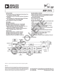
ADSP-2181
ADSP-2181 can fetch an operand from program memory and
the next instruction in the same cycle.
In addition to the address and data bus for external memory
connection, the ADSP-2181 has a 16-bit Internal DMA port
(IDMA port) for connection to external systems. The IDMA
port is made up of 16 data/address pins and five control pins.
The IDMA port provides transparent, direct access to the DSPs
on-chip program and data RAM.
An interface to low cost byte-wide memory is provided by the
Byte DMA port (BDMA port). The BDMA port is bidirectional
and can directly address up to four megabytes of external RAM
or ROM for off-chip storage of program overlays or data tables.
The byte memory and I/O memory space interface supports slow
memories and I/O memory-mapped peripherals with programmable wait state generation. External devices can gain control of
external buses with bus request/grant signals (BR, BGH and BG).
One execution mode (Go Mode) allows the ADSP-2181 to continue running from on-chip memory. Normal execution mode
requires the processor to halt while buses are granted.
The ADSP-2181 can respond to 13 possible interrupts, eleven
of which are accessible at any given time. There can be up to six
external interrupts (one edge-sensitive, two level-sensitive and
three configurable) and seven internal interrupts generated by
the timer, the serial ports (SPORTs), the Byte DMA port and
the power-down circuitry. There is also a master RESET signal.
The ADSP-2181 provides up to 13 general-purpose flag pins.
The data input and output pins on SPORT1 can be alternatively
configured as an input flag and an output flag. In addition, there
are eight flags that are programmable as inputs or outputs and
three flags that are always outputs.
A programmable interval timer generates periodic interrupts. A
16-bit count register (TCOUNT) is decremented every n processor cycles, where n is a scaling value stored in an 8-bit register (TSCALE). When the value of the count register reaches
zero, an interrupt is generated and the count register is reloaded
from a 16-bit period register (TPERIOD).
Serial Ports
The ADSP-2181 incorporates two complete synchronous serial
ports (SPORT0 and SPORT1) for serial communications and
multiprocessor communication.
Here is a brief list of the capabilities of the ADSP-2181 SPORTs.
Refer to the ADSP-2100 Family User’s Manual, Third Edition for
further details.
• SPORTs are bidirectional and have a separate, doublebuffered transmit and receive section.
• SPORTs can use an external serial clock or generate their
own serial clock internally.
• SPORTs have independent framing for the receive and transmit sections. Sections run in a frameless mode or with frame
synchronization signals internally or externally generated.
Frame sync signals are active high or inverted, with either of
two pulsewidths and timings.
The two serial ports provide a complete synchronous serial interface with optional companding in hardware and a wide variety of
framed or frameless data transmit and receive modes of operation.
Each port can generate an internal programmable serial clock or
accept an external serial clock.
21xx CORE
ADSP-2181 INTEGRATION
POWERDOWN
CONTROL
LOGIC
INSTRUCTION
REGISTER
DATA
ADDRESS
GENERATOR
#1
DATA
ADDRESS
GENERATOR
#2
PROGRAM
SRAM
16K 3 24
DATA
SRAM
16K 3 16
BYTE
DMA
CONTROLLER
2
8
PROGRAMMABLE
I/O
3
PROGRAM
SEQUENCER
FLAGS
PMA BUS
14
PMA BUS
DMA BUS
14
DMA BUS
14
MUX
EXTERNAL
ADDRESS
BUS
PMD BUS
24
PMD BUS
EXTERNAL
DATA
BUS
BUS
EXCHANGE
DMD
BUS
DMD BUS
MUX
24
16
INPUTREGS
REGS
INPUT
INPUTREGS
REGS
INPUT
INPUT REGS
ALU
ALU
MAC
MAC
SHIFTER
OUTPUT REGS
REGS
OUTPUT
OUTPUTREGS
REGS
OUTPUT
OUTPUT REGS
COMPANDING
CIRCUITRY
TIMER
16
TRANSMIT REG
TRANSMIT REG
RECEIVE REG
RECEIVE REG
SERIAL
PORT 0
SERIAL
PORT 0
R BUS
5
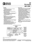
Figure 1. ADSP-2181 Block Diagram
REV. D
–3–
5
INTERNAL
DMA
PORT
16
4
INTERRUPTS