1
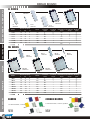
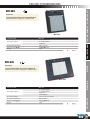
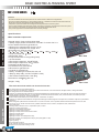
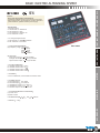
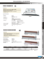
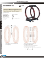
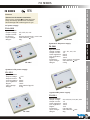
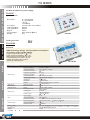
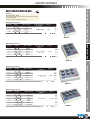
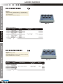
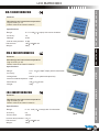
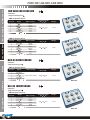
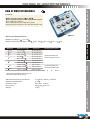
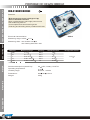
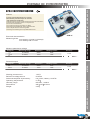
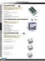
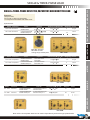
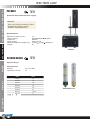
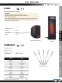
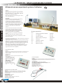
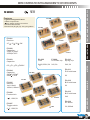
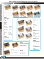
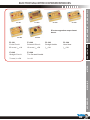
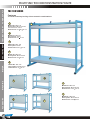
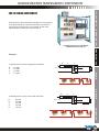
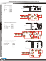
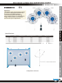
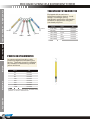
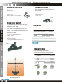
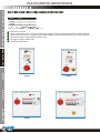
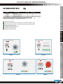
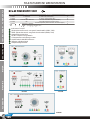
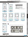
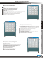
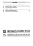
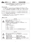
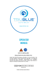
EDUCATION
EQUIPMENTS
ELECTRICAL TRAINING SYSTEM
RHEOSTAT
LAB DECADE BOX
ULTRASONIC WAVES EXPERIMENT SYSTEM
MECHANICS PRINCIPLE EXPERIMENT SYSTEM
AND MORE...
Content
50 -
Lab decade box
51 52 53 54 55 56 57 -
LCR matrix box
Single & three-phase load
Page 85
Page 86
Page 87
Page 88
Page 89
Page 90
Page 91
Page 92
Page 93
Page 94
Page 95
Page 96
Page 97
Page 98
Page 99
Page 100
Page 101
Page 102
Page 103
Page 104
Page 105
Page 106
58 -
Spectrum lamp
Page 107
P228001
P2281XX
P2181XX
Ultrasonic waves experiment system
Page 108
Page 109
Page 110
Page 113
Page 116
Page 118
Page 119
Page 120
Page 122
P218001
59 60 61 62 -
42 43 44-
Bread board
Power project board
Basic electrical training system
45 -
Digital training system
46 -
Rheostat
47 48 49 -
Teslameter & solenoid
Helmholtz coil
F8 series
Precise lab decade box
Protable dc wheatstone bridge
Portable dc kelvin bridge
Portable dc potentiometer
Experiment box
LL series
BL series JBL series
ML series
M21-500
M21-600
M21-1000
M21-1100
M21-2000
M21-3000
M21-5000
M21-7000
BXS series
BXD series
TM204
RXG250 series
RXH
F8-A1202 F8-5801
F8-1505
F8-1501
F8-1201
F8-LG100
BXR seires
BXL-07 series & BXC-05 series
RM-7
CM-5
IM-4
DBR series & DBL series & DBC series
DWB-01 wheatstone bridge
DKB-01 kelvin bridge
DPM-01 dc potentiometer
F5-001
F20-101
SRL-1000/TRL-3000
F4 series
SCL-1000/TCL-3000
SIL-1000/TIL-3000
63 64 -
Demonstration transparent component
Multi function demonstration frame
Mechanics principle experiment system
Training bench
Multi-purpose workstation
P416000/F16-014/F16-015...
F3 series
TB100 series
Dynamometeres
Pulleys & Weight sets
Various
TB series
TB150 series multi-purpose workstation
One-phase and three-phase
mains control unit
AC power supply unit
DC & AC power supply unit
Meters & sockets
65 -
Education house
Page 127
EH 818
LL SERIES
LL-11
740 holes
LL-21B
1380 holes
LL-10
640 holes
Model
LL-01
100 holes
Dimension(mm)
Terminal
holes
-
Terminal
strips
640
640
1
8
740
640
62
8
840
220
120
9
220
165
9
Holes
W
H
LL-01
170
12
8
100
LL-10
170
38
8
LL-11
170
40
LL-12
170
LL-21B
LL-24B
-
Distribution Distribution Binding
holes
strips
post
-
100
-
-
1
100
1
640
1
200
2
1380
1280
2
100
1
2
1380
1280
2
400
4
3
1
ML SERIES
ML-35B
2390 holes
MACHINE
ML-24B
1660 holes
Dimension(mm)
Terminal
holes
-
630
630
1
8
730
630
8
830
630
120
9
830
220
165
9
220
120
9
220
165
9
W
H
ML-01
170
12
8
100
ML-10
170
38
8
ML-11
170
40
ML-12
170
62
ML-21B
220
ML-24B
ML-35B
ML-47B
MCP
R
085
-
-
-
1
100
1
1
200
2
630
1
200
2
2
1660
1260
2
400
4
3
2390
1890
3
500
5
4
3220
2520
4
700
7
4
1
JBL2
BL6
BL1
JBL6
JBL3
JOINABLE BLOCKS
170 terminal holes, 7 colours, joinable
BL7
BL2
lab electronics
-
Distribution Distribution Binding
holes
strips
post
100
170 terminal holes, 7 colours
NEW
ML-47B
3220 holes
Terminal
strips
Holes
L
BLOCKS
ML-01
100 holes
ML-10
630 holes
ML-11
730 holes
ML-12
830 holes
Model
ACCESSORY
LL-24B
1680 holes
LL-12
840 holes
L
METER
SUPPLY
EDU. INSTRUMENT TEST INSTRUMENT POWER
POWER
SUPPLY
BREAD BOARD
BL3
JBL4
BL5
BL4
JBL5
NEW
JBL1
JBL7
SUPPLY
EDU. INSTRUMENT TEST INSTRUMENT POWER
POWER
SUPPLY
PROJECT POWER BOARD
M21-500
Features
.Low cost but ideal tool for breadboard
.With DC power supply for common use
M21-500
Technical Data
M21-500
0~+15VDC/500mA
0~-15VDC/500mA
+5VDC/1A
DC Output Voltage
Solderless Breadboard
2390 tie points
Dimensions(W
200
H
D)
Weight
80
250mm
4.5kg
M21-600
METER
Features
.Low cost but ideal tool for breadboard
.With DC, AC power supply for common use
Technical Data
MACHINE
M21-600
M21-600
DC Output Voltage
0~-15VDC/500mA
+5VDC/1A
-5VDC/500mA
AC Output Voltage
12V-6V-0-6V-12V, 300mA
Solderless Breadboard
2820 tie points
Dimensions(W
334
Weight
H
D)
95
ACCESSORY
0~+15VDC/500mA
258mm
4.5kg
R
MCP
lab electronics
086
METER
SUPPLY
EDU. INSTRUMENT TEST INSTRUMENT POWER
POWER
SUPPLY
BASIC ELECTRICAL TRAINING SYSTEM
M21-1000 SERIES
Features
.Provide available electrical components and interconnect in different configurations.
.Acquire the basic knowledge on electrical engineering, installations and electrical measurements.
.Study the means to check the main laws and principles.
.Component symbols and electrical diagrams are represented on the front panel.
.The symbols and electrical diagrams of each component are clearly represented on the front panel.
.The connections are eased by 4mm terminals and cables of different colors.
.The power supplies are included with extra low safety voltage.
Specifications
Main installed components:
General switch, fuse and signaling lamp
1 Safety single-phase transformer 115-230V / 6-12-24 VAC-1 A
2 Fuse-holder with fuse type 6x30-1A
1 Moving iron ammeter with range: 0.5-1A
1 Moving iron voltmeter with range: 25 V
10 Resistors of different values
(2 , 4 , 8 , 16 , 31.5 , 63 , 250 , 500 , 1000 , 2000 )
1 linear rheostat 100
/25W
4 Diodes 6A-100V
2 Lamp-holder with 24-V signaling lamp
1 24-Vac buzzer
1 Electrolytic capacitor, 100 F25Vdc
2 Electrolytic capacitors, 500 F25Vdc
2 Inductances 60 mH 0.5 A
2 Pushbuttons for general use
2 Shunters for general use
1 Inverter for general use
1 Relay, 2 exchange contacts, 24 Vac coil
1 Step-by-step relay, 24-Vac coil (M21-1100)
1 Set of 25mm cables with 4-mm plug
Dimensions: 258 95
M21-1000
334 mm
Weight: 4.5kg
M21-1100
ACCESSORY
MACHINE
The main exercises which can be carried out are:
AC voltage and current measurements
Diode insertion with different configurations Half-wave rectifier, Full-wave rectifier, Bridge rectifier, Voltage doublers
DC voltage and current measurements
Insertion of resistances with different configurations Resistance measurements, Checking the Ohm's law, Series resistors,
voltage divider, Parallel resistors, current divider, series and parallel resistors, max. power transfer, Kirchhoff's principle,
superimposition principle, Thevenin's theorem
Power measurements DC power measurement, Joule's law, AC power
Insertion of capacitors with different configurations Charge and discharge of a DC capacitor, series DC capacitors, parallel DC
capacitors
Electromagnetic phenomena Inductance of a coil, coils in series, coils in parallel, Ohmic/inductive/capacitive circuits, RC
circuit, RL circuit, series resonant circuit, parallel resonant circuit, Q-factor, coupled circuits, attenuators
The transformer
Leveling filters Inductive circuit, capacitive input, LC filter
Lighting of a lamp with switch
Lighting of more lamps with switch
Lighting of a lamp with shunters
Lighting of a lamp with shunters and inverter
Lighting of a hotel room
Lighting of a file room
Lighting of one or more lamps with relay
Lighting of one or more lamps with step-by-step relay (M21-1100)
Acoustic signaling
Light signaling
Acoustic/light signaling
Pulse remote control of a user with relay
Remote control with self-holding circuit
MCP
R
lab electronics
087
SUPPLY
EDU. INSTRUMENT TEST INSTRUMENT POWER
POWER
SUPPLY
BASIC ELECTRICAL TRAINING SYSTEM
NEW
M21-2000
Feature
. High level, high quality analog trainer
. Combines all essential function of analog experiment
. With analog meters, digital meters, function generator,
potentiometers, speaker and DC power supply
Specification
1. Analog meters:
A. AC ammeter: 0~100mA~1A
B. AC voltmeter: 0~30V
C. DC ammeter: 0~100mA~1A
D. DC voltmeter: 0~30V
2. 3 1/2 digits digital meters:
A. DC Ammeter: 0~2000 A~2000mA
B. DC voltmeter: 0~2V~200V
M21-2000
3. FUNCTION GENERATOR
(A)Frequency range: 1Hz 10Hz
10Hz 100Hz
100Hz 1kHz
1kHz 10kHz
10kHz 100kHz
(B)Amplitude
Sine wave output 0 10 Vpp variable
Triangle wave output 0 10 Vpp variable
Square wave output 0 10 Vpp variable
METER
4. POTENTIOMETERS:
A. Variable resistor VR1 = 100
B. Variable resistor VR2 = 1k
C. Variable resistor VR2 = 10k
D. Variable resistor VR2 = 100k
5. SPEAKER
2-1/2 inch diameter, 8 ohm/0.5W to be used for load.
MACHINE
6. POWER SUPPLY :
A. Fixed DC output +5V, 500A
B. Fixed DC output -5V, 500m A.
C. Variable DC output 0 to +15V, 1 A
D. Variable DC output 0 to 15V, 1 A
E. Fixed AC output: 12V-6V-0-6V-12V
7. OTHER STANDARD ACCESSORIES
(1) Power cord
(2)User manual
8. DIMENSIONS(W H
258
95
334mm
4.5kg
ACCESSORY
9. WEIGHT
D)
R
MCP
lab electronics
088
METER
SUPPLY
EDU. INSTRUMENT TEST INSTRUMENT POWER
POWER
SUPPLY
BASIC ELECTRICAL TRAINING SYSTEM
NEW
M21-3000
Feature
. High level, high quality digital-analog trainer
. Combines all essential function of digital experiment
. With DC power supply, IC sockets, two pulse switches,
data switch, LED data display, pulse switch, BCD display
and clock
Specification
1. IC sockets:
6 IC 20 pins sockets
2. DC POWER SUPPLY :
Fixed DC output +5V, 1A
M21-3000
3. SIXTEEN BITS DATA SWITCHES :
16pcs toggle switches and corresponding output point.
When switch is set at down position,the output is
LO level; contrarily, it is to be HI level while setting at
up position.
4. SIXTEEN BITS LED DISPLAY
16 red LED's separate input terminals. The LED
will be lighted up when input is at HI level ,and
it will be turned off when it is at no input or at LO level .
5. TWO PULSE SWITCH
(WITH 2 SET OF OUTPUT (A , A ,B , B))
2pcs pushbuttons contain switches debouncer for
eliminating the bounce caused by switch from open
to close or from close to open position.
6. TWO DIGITS OF 7 SEGMENT LED DISPLAY
(A) Output display
Numerical designs and resultant displays
0 12 3 4 56 78 9
0
1
2
3
4
5
7
6
8
56
9 10 11 12 13 14 15
MACHINE
segment identification
8
a
f g b
e
c
d
ACCESSORY
7. OTHER STANDARD ACCESSORIES
(1) Power cord
(2) Pin : 10cm 20pcs/20cm 20pcs
(3) User manual
8. DIMENSIONS(W H
9. WEIGHT
MCP
R
lab electronics
089
4.5kg
D): 258 95
334mm
(B) Function tables
Decimal
Or
Function
0
1
2
3
4
5
6
7
8
9
10
11
12
13
14
15
Inputs
D
L
L
L
L
L
L
L
L
H
H
H
H
H
H
H
H
C
L
L
L
L
H
H
H
H
L
L
L
L
H
H
H
H
B
L
L
H
H
L
L
H
H
L
L
H
H
L
L
H
H
Outputs
A
L
H
L
H
L
H
L
H
L
H
L
H
L
H
L
H
a
L
H
L
L
H
L
H
L
L
L
H
H
H
L
H
H
b
L
L
L
L
L
H
H
L
L
L
H
H
L
H
H
H
c
L
L
H
L
L
L
L
L
L
L
H
L
H
H
H
H
d
L
H
L
L
H
L
L
H
L
H
L
L
H
L
L
H
e
L
H
L
H
H
H
L
H
L
H
L
H
H
H
L
H
f
L
H
H
H
L
L
L
H
L
L
H
H
L
L
L
H
g
H
H
L
L
L
L
L
H
L
L
L
L
L
L
L
H
DIGITAL TRAINING SYSTEM
SUPPLY
EDU. INSTRUMENT TEST INSTRUMENT POWER
POWER
SUPPLY
M21-5000
Feature
. High level, high quality digital trainer
. Combines all essential function of digital experiment
. With removable breadboard, DC power supply,
pulse generator, two pulse switches, digital probe,
TTL/CMOS selector and etc.
Specification
1. SOLDERLESS BREADBOARD :
Interconnected with 2820 tie points nickel plated contact,
fitted all DIP sizes and all components with lead and solid
wire AWG # 22-30 (0.3-0.8mm).It can be changed and
replaced for different purpose and can be connected with
demonstration panel. Therefore, it is very convenient for
both teachers and students.
2. DC POWER SUPPLY :
A. Fixed DC output +5V, 1A
B. Fixed DC output -5V, 1 A.
C. Variable DC output +3V to +15V, 1 A
D. Variable DC output -3V to 15V, 1 A.
M21-5000
3. MODE SELECTOR SWITCH:
When the switch is put on "TTL" or "CMOS" position, the
input or output of pulse generator, pulser switches, 8 bits
data switches digital probe, 8 bit LED display will meet the
HI or LO level of "TTL" or "CMOS".
Optional accessories
4. TWO DIGITS OF 7 SEGMENT LED DISPLAY
5. PULSE GENERATOR
(A) Duty cycle: 50%
(B) Frequency range:
0.8 0.2V
2.3 0.2V
0.8 ~ 2.3
Green
Red
No display
Set mode selector switch to "CMOS" position
Logic
Input level
Display light up
Level
LO
30%+VDC 10%
Green
HI
70%+VDC 10%
Red
Open
30% ~ 70% +VDC
No display
7. TWO PULSE SWITCH:
A,/A,B,/B output
Output level:
TTL: HI=4V LO=0.1V
CMOS: HI=+VDC LO=0.1V
8. SIXTEEN DATA SWITCHES:
TTL: HI=4V LO=0V
CMOS: HI=+VDC LO=0V
9. DIGITAL PROBES:
Set mode selector switch to "TTL" position
Logic
Input level
Display light up
Level
LO
HI
Open
Transit
0.8 0.2V
2.3 0.2V
0.8 ~ 2.3
LO-- HI
L
H
O
P
Logic
Level
LO
HI
Open
Transit
Input level
Display light up
30%+VDC 10%
70%+VDC 10%
30% ~ 70% +VDC
LO-- HI
L
H
O
P
MACHINE
LO
HI
Open
Set mode selector switch to "CMOS" position
Memory: the two points of LED beside 7 segment
LED display will keep lighting when they
are in "level transition" (LO-- HI or HI-- LO)
10. UNIVERSAL CONNECTOR FIXED HOLDER
It reserves universal connector fixed holder on the panel
in order to be connected with various universal connectors,
which are available as below
optional accessories
(1) Straight header 60 pin
(2) Card edge connector 2.54mm 62pin
(3) D sub25 pin connector, male & female
(4) Card edge connector 3.96mm 56pin
(5) Dip sockets connector 28 pin & 40 pin
ACCESSORY
6. SIXTEEN BITS LED DISPLAY
Set mode selector switch to "TTL" position
Logic
Input level
Display light up
Level
METER
1Hz ~ 10Hz
10Hz ~ 100Hz
100Hz ~ 1kHz
1kHz ~ 10kHz
10kHz ~ 100kHz
100kHz ~ 1MHz
(C) Amplitude: 0 ~ 10Vpp
(D) TTL/CMOS mode output
TTL: + 4V
CMOS: + VDC (depend on the + VDC output)
11. OTHER STANDARD ACCESSORIES
(1) Power cord
(2) Pin : 10cm 20pcs/20cm 20pcs
(3).User manual
12. DIMENSIONS(W H
13. WEIGHT
D)
258
95
334mm
4.5kg
R
MCP
lab electronics
090
MACHINE
METER
SUPPLY
EDU. INSTRUMENT TEST INSTRUMENT POWER
POWER
SUPPLY
DIGITAL TRAINING SYSTEM
M21-7000
Feature
. High level, high quality digital-analog trainer
. Combines all essential function of analog and digital
experiment
. With removable breadboard, DC power supply,
function generator, two pulse switches, 2 1/2 inch
8 ohm 0.5W speaker and etc.
Specification
1. SOLDERLESS BREADBOARD :
Interconnected with 2820 tie points nickel
plated contact, fitted all DIP sizes and all
components with lead and solid wire
AWG # 22-30 (0.3-0.8mm).It can be changed
and replaced for different purpose and can be
connected with demonstration panel.
Therefore, it is very convenient for both teachers
and students.
2. DC POWER SUPPLY :
A. Fixed DC output +5V, 1A
B. Fixed DC output -5V, 1 A
C. Variable DC output 0V to +15V, 1 A.
D. Variable DC output 0V to 15V, 1 A.
M21-7000
3. POTENTIOMETERS:
A. Variable resistor VR1 = 1k
B. Variable resistor VR2 = 100k
(B) Function tables
4. FUNCTION GENERATOR
(A)Frequency range: 1Hz 10Hz
10Hz 100Hz
100Hz 1kHz
1kHz 10kHz
10kHz 100kHz
(B)Amplitude
Sine wave output 0 10 Vpp variable
Triangle wave output 0 10 Vpp variable
Square wave output 0 10 Vpp variable
TTL mode output 4 Vpp
5. SIXTEEN BITS DATA SWITCHES :
16pcs toggle switches and corresponding output point.
When switch is set at down position,the output is
LO level; contrarily, it is to be HI level while setting at
up position.
6. TWO PULSE SWITCH
(WITH 2 SET OF OUTPUT (A , A ,B , B))
2pcs pushbuttons contain switches debouncer for
eliminating the bounce caused by switch from open
to close or from close to open position.
7. SPEAKER
2-1/2 inch diameter, 8 ohm/0.5W to be used for load.
8. FOUR CHANNEL ADAPTOR
Both of the two banana sockets' and two BNC jacks'
point tips are changeable. It is suitable for M21-7000
to be connected with peripherals.
9. TWO DIGITS OF 7 SEGMENT LED DISPLAY
(A) Output display
Numerical designs and resultant displays
ACCESSORY
Optional accessories
0 12 3 4 56 78 9
0
1
2
3
4
5
6
segment identification
MCP
R
lab electronics
091
7
8
56
9 10 11 12 13 14 15
8
a
f g b
e
c
d
Decimal
Or
Function
0
1
2
3
4
5
6
7
8
9
10
11
12
13
14
15
Inputs
D
L
L
L
L
L
L
L
L
H
H
H
H
H
H
H
H
C
L
L
L
L
H
H
H
H
L
L
L
L
H
H
H
H
B
L
L
H
H
L
L
H
H
L
L
H
H
L
L
H
H
Outputs
A
L
H
L
H
L
H
L
H
L
H
L
H
L
H
L
H
a
L
H
L
L
H
L
H
L
L
L
H
H
H
L
H
H
b
L
L
L
L
L
H
H
L
L
L
H
H
L
H
H
H
c
L
L
H
L
L
L
L
L
L
L
H
L
H
H
H
H
d
L
H
L
L
H
L
L
H
L
H
L
L
H
L
L
H
e
L
H
L
H
H
H
L
H
L
H
L
H
H
H
L
H
f
L
H
H
H
L
L
L
H
L
L
H
H
L
L
L
H
g
H
H
L
L
L
L
L
H
L
L
L
L
L
L
L
H
10. SIXTEEN BITS LED DISPLAY
16 red LED's separate input terminals. The LED
will be lighted up when input is at HI level ,and
it will be turned off when it is at no input or at LO level .
11. UNIVERSAL CONNECTOR FIXED HOLDER
It reserves universal connector fixed holder on the panel
in order to be connected with various universal connectors,
which are available as below
optional accessories
(1) Straight header 60 pin
(2) Card edge connector 2.54mm 62pin
(3) D sub25 pin connector, male & female
(4) Card edge connector 3.96mm 56pin
(5) Dip sockets connector 28 pin & 40 pin
12. OTHER STANDARD ACCESSORIES
(1) Power cord
(2) Pin : 10cm 20pcs/20cm 20pcs
(3) User manual
13. DIMENSIONS(W H
14. WEIGHT
4.5kg
D): 258 95
334mm
SUPPLY
EDU. INSTRUMENT TEST INSTRUMENT POWER
POWER
SUPPLY
RHEOSTAT
BXS SERIES
Feature
. 100 scale division to show the resistance setting.
. Enclose in robust sheet metal cover
. Good linearity
. Sliding contact of coppers graphite
BXS 150
160
BXS 300
320
BXS 600
640
Resistance
( )
3.3
10
33
100
330
1000
3300
3.3
10
33
100
330
1000
3300
10000
1.6
5
16.5
50
165
500
1650
5000
Max.
Current
7A
4A
2.2A
1.25A
0.7A
0.4A
0.22A
10A
5.7A
3.1A
1.8A
1.0A
0.57A
0.31A
0.18A
20A
11.4A
6.2A
3.6A
2A
1.1A
0.63A
0.36A
Dimensions
(W H D)
Ceramic
Pipe diameter
Weight
(kg)
285
140
95mm
47mm
1.8
385
140
95mm
47mm
2.4
100mm
64mm
3.2
485
160
METER
Power
VA
BXS 600
MACHINE
Model
380VAC, 400VDC
10%
3 10 9
0.1
see table
ACCESSORY
Specifications
. Max. Working Voltage:
. Resistance tolerance:
. Insulation resistance:
. Earthing resistance:
. Rated resistance:
R
MCP
lab electronics
092
BXD SERIES
Feature
. 100 scale division to show the resistance setting.
. Good linearity
. Fused safety socket of the slide bar
. Enclose in robust sheet metal cover
. Sliding contact of coppers graphite
. More tighter structure
. New appearance design
Specifications
. Max. working voltage:
. Resistance tolerance:
. Insulation resistance:
. Earthing resistance:
. Rated resistance:
Model
ACCESSORY
MACHINE
METER
SUPPLY
EDU. INSTRUMENT TEST INSTRUMENT POWER
POWER
SUPPLY
RHEOSTAT
MCP
R
lab electronics
093
380VAC, 400VDC
10%
3 10 9
0.1
see table
Power
VA
BXD160
160
BXD300
320
BXD600
640
Resistance
( )
3.3
10
33
100
330
1000
3300
3.3
10
33
100
330
1000
3300
10000
1.6
5
16.5
50
165
500
1650
5000
BXD160
Max.
Current
7A
4A
2.2A
1.25A
0.7A
0.4A
0.22A
10A
5.7A
3.1A
1.8A
1.0A
0.57A
0.31A
0.18A
20A
11.4A
6.2A
3.6A
2A
1.1A
0.63A
0.36A
BXD300
Dimensions
(W H D)
Ceramic
Pipe diameter
Weight
kg
240
180
195mm
64mm
2.2
380
180
100mm
64mm
2.8
480
180
100mm
64mm
3.5
SUPPLY
EDU. INSTRUMENT TEST INSTRUMENT POWER
POWER
SUPPLY
TESLAMETER & SOLENOID
TM204 TESLAMETER
Features
.Switching measures of BX and BZ
.Biaxial probe removable and graduation provided
.Double sensors protection
.2 ranges of measure:20 mT or 100mT
.Analog output
Specifications
.Range:
.Display:
.Resolution:
.Accuracy:
.Analog:
.Power supply:
.Dimensions:
.Weight:
20mT
200mT
2000 digits LCD
10 T
2%Rdg
3 digits (20mT)
2%Rdg
1 digit (100mT)
Sensitivity:
10mV/mT(20mT)
1mV/mT(100mT)
Impendence: 4.7k
Connection:
safety socket 4mm
220-240V, 50-60Hz
230(W) 85(H) 240(D)mm
1kg
TM204
RXG250 SERIES SOLENOID
.Simple application allows you to perform
various manipulations
.Influence of L, I and the number of turns
.Axial guide for teslameter probes
METER
Features
RXG250
Specifications
500mm
Ceramic
50mm
Copper wires
620(W) 100(H)
3kg
RXG250B
MACHINE
.Pipe length:
.Pipe material:
.Pipe diameter:
.Windings material:
.Dimensions:
.Weight:
120(D)mm
RXG250T
RXG250
RXG250B
RXG250T
Windings
2
250T
500T
250T+250T
Windings diameter
I max
0.92mm
7A(parallel)
0.92mm
1.0mm, 0.77mm
3.5A
3.5A
Intermediary terminals
ACCESSORY
Model
R
MCP
lab electronics
094
RXH HELMHOLTZ COIL
NEW
Features
.Pair of coils in Helmholtz configuration used to
produce a homogeneous magnetic field
.The coils can be switched in parallel or in series
.A spring clip is used to mount the Hall sensor
Specifications
.Coil diameter:
.Max. field:
.Number of turns:
.DC resistance:
.Max. coil current:
.Terminals:
.Weight:
Approx. 300mm
3.8mT
124
1.2
5A
4mm safety socket
4kg
RXH
MACHINE
METER
SUPPLY
EDU. INSTRUMENT TEST INSTRUMENT POWER
POWER
SUPPLY
HELMHOLTZ COIL
ACCESSORY
The mean coil radius is the same as
the coil spacing.
There is am uniform magnetic field
in the pair of Helmholtz coil.
The magnetic field's direction depends
on current's direction of the coil.
The magnetic flux density B of the magnetic field:
3
2
4
B= ( - )
5
MCP
R
lab electronics
095
0
I
n
R
F8 SERIES
NEW
SUPPLY
EDU. INSTRUMENT TEST INSTRUMENT POWER
POWER
SUPPLY
F8 SERIES
Features
.Plastic box for double insulation
.Dimensions: 240(W) 90(H) 170(D)mm
.Easy and safety operation for students
.Novel design and various types for you
AC power supply
F8-A1202
Specifications
.Output voltage:
.Output current:
.Protection:
.Input voltage:
.Weight:
2V, 6.3V, 9V, 12V
2A
Output short(buzzer), over heat
220~240VAC 10%
2kg
F8-A1202
Symmetric DC power supply
F8-5801
+5V, -5V, +8V, -8V
1A
50mV
50mV
10mV
Over current, over heat
220~240VAC 10%
2.5kg
METER
F8-5801
Specifications
.Output voltage:
.Output current:
.Load regulation:
.Line regulation:
.Ripple:
.Protection:
.Input voltage:
.Weight:
Symmetric DC power supply
15V
1A
20mV
20mV
10mV
220~240VAC
2.5kg
10%
F8-1501
regulated DC power supply
F8-1201
F8-1201
Specifications
.Output voltage:
.Output current:
.Load regulation:
.Line regulation:
.Ripple:
.Protection:
.Input voltage:
.Weight:
ACCESSORY
Specifications
.Output voltage:
.Output current:
.Load regulation:
.Line regulation:
.Ripple:
.Input voltage:
.Weight:
MACHINE
F8-1501
3V, 4.5V, 6V, 7.5V, 9V, 12V
1A
10mV
10mV
1mV
Current limit
220~240VAC 10%
2kg
R
MCP
lab electronics
096
METER
SUPPLY
EDU. INSTRUMENT TEST INSTRUMENT POWER
POWER
SUPPLY
F8 SERIES
AC & DC breadboard power supply
F8-1505
Specifications
.DC output:
.AC output:
.Load regulation:
.Line regulation:
.Ripple:
.Input voltage:
.Weight:
Audio generator
F8-LG100
NEW
.DDS technology design, ultra-low power consumption
.Frequency range: 0.01Hz~30kHz-6
.High frequency accuracy: 1 x 10⁻⁶
.High frequency stability: 1 x 10
.Max frequency resolution: 0.01Hz
.Low distortion sine wave: <0.8%
.Audio input and power output
.Optional USB interface
F8-LG100
Technical Data
Output frequency
Output waveforms
Frequency accuracy
Frequency resolution
Frequency stability
Output amplitude
Amplitude accuracy
Impedance
DC offset
Display
Sine wave
Square wave
Triangle wave
Audio input
Distortion factor
Rise or fall time
Linear
Frequency range
Voltage gain
Power output
ACCESSORY
F8-1505
Features
Main output
MACHINE
0~+15V/500mA
0~-15V/500mA
+5V/1A
-5V/500mA
12V-6V-0-6V-12V, 300mA
200mV
200mV
20mV
220~240VAC 10%
3kg
VCF
Power output
Power supply
Dimensions
Weight
MCP
R
lab electronics
097
Input voltage
Input impedance
Frequency change
Output amplitude
Output impedance
Output current
0.01Hz ~ 30kHz
Sine, Square, Triangle
5 x 10 -6
0.01Hz
1 x 10 -6
0.2~20Vp-p (no load)
10% (1kHz, 20Vp-p)
50
10%
5V (no load)
3 digits LED for frequency display
0.8% (at 1kHz)
5 us
98% 100Hz~100kHz
20Hz~20kHz
0~40dB
1.5W (4 load)
3W (8 load)
0~5V
10k
10%
0 to the current set of frequency value
20Vp-p (no load)
18Vp-p (10 load)
4
0.6Amrs
110~127 VAC 10%, 220~240VAC 10%, 50Hz 2Hz / 60Hz 2Hz
240(W) 90(H) 170(D)mm
1.5 kg
SUPPLY
EDU. INSTRUMENT TEST INSTRUMENT POWER
POWER
SUPPLY
LAB DECADE BOX
BXR SERIES RESISTOR BOX
Features
.High accuracy to 1%
.Economical, high performance high resistance decade
for all laboratory
.Plastic cabinet for better insulation
BXR-04 Specifications
Decade
1
2
Range
Max. Current
~10
1
3
10 ~100
100 ~1k
700mA
200mA
70mA
4
1k ~10k
20mA
Dimension(mm)
(L W H)
190
140
Weight
80
0.5kg
BXR-04
BXR-05 Specifications
Decade
1
2
3
4
5
Range
Max. Current
~10
700mA
200mA
70mA
1
10 ~100
100 ~1k
1k ~10k
10k ~100k
Dimension(mm)
(L W H)
190
140
80
Weight
0.5kg
20mA
7mA
METER
BXR-05
BXR-06 Specifications
1
2
3
1
Range
Max. Current
~10
700mA
200mA
70mA
10 ~100
100 ~1k
4
5
1k ~10k
10k ~100k
20mA
7mA
6
100k ~1M
1mA
Dimension(mm)
(L W H)
170
240
90
Weight
0.8kg
MACHINE
Decade
BXR-06
Decade
1
2
3
1
Range
Max. Current
~10
700mA
200mA
70mA
10 ~100
100 ~1k
4
5
1k ~10k
10k ~100k
20mA
7mA
6
100k ~1M
1mA
7
1M ~10M
0.11mA
Dimension(mm)
LxWxH
Weight
170x240x90
0.8Kg
ACCESSORY
BXR-07 Specifications
BXR-07
R
MCP
lab electronics
098
METER
SUPPLY
EDU. INSTRUMENT TEST INSTRUMENT POWER
POWER
SUPPLY
LAB DECADE BOX
BXL-07 INDUCTOR BOX
Features
.High accuracy to 5%(decade 1~6); 10%(decade 7)
.Economical, high performance high resistance decade
for all laboratory
.Plastic cabinet for better insulation
BXL-07
BXL-07 Specifications
3
10 H~100 H
100 H~1mH
Max.DC
Current
300mA
200mA
100mA
4
1mH~10mH
100mA
5
10mH~100mH
70mA
6
7
100mH~1H
1H~10H
50mA
Range
Decade
1
2
1
H~10 H
Dimension(mm)
(L W H)
170
240
90
Weight
1.2kg
40mA
BXC-05 CAPACITOR BOX
BXC-05
BXC-05 Specifications
Decade
Range
1
2
0.1nF~1nF
1nF~10nF
3
10nF~100nF
4
100nF~1 F
1 F~10 F
ACCESSORY
MACHINE
Features
.High accuracy to 5%
.Economical, high performance high resistance decade
for all laboratory
.Plastic cabinet for better insulation
5
MCP
R
lab electronics
099
Max.Voltage
300V DC /230V AC (50Hz)
Dimension(mm)
(L W H)
170
240
90
Weight
0.8kg
LCR MATRIX BOX
SUPPLY
EDU. INSTRUMENT TEST INSTRUMENT POWER
POWER
SUPPLY
RM-7 RESISTOR MATRIX
Features
.New design and convenience operation
.High accuracy to 1%
.Plastic cabinet for better insulation
Specifications
Range:
0~11.111M (1
Accuracy:
1%
Wattage:
0.5W
steps) with seven decades
Internal stray resistor: 0.3
Dimensions:
190 140 80 mm
Weight:
400g
RM-7
CM-5 CAPACITOR MATRIX
Features
.New design and convenience operation
.High accuracy to 5%
.Plastic cabinet for better insulation
Range:
0~11.111 F(100pF steps) with five decades
Accuracy:
5%
Voltage limit:
50VDC (non-polarized capacitor)
METER
Specifications
CM-5
Dimensions:
190 140 80 mm
Weight:
350g
MACHINE
Internal residual capacitor: 50pF
IM-4 INDUCTOR MATRIX
Features
.New design and convenience operation
.High accuracy to 5%
.Plastic cabinet for better insulation
Range:
0~111.1mH (10 H steps) with four decades
Accuracy:
5%
Current limit:
100mA
ACCESSORY
Specifications
IM-4
Internal stray inductor: 0.6 H
Dimensions:
190 140 80 mm
Weight:
450g
R
MCP
lab electronics
100
SUPPLY
EDU. INSTRUMENT TEST INSTRUMENT POWER
POWER
SUPPLY
PRECISE LAB DECADE BOX
DBR SERIES RESISTOR BOX
Features
. High accuracy to 1
DBR-06 Specifications
Decade
Range
0.1
10
1
10
10
10
100
10
1000
10
10000
10
1
2
3
4
5
6
Max. Current
Dimension(mm)
(W H D)
Weight
700mA
700mA
200mA
70mA
20mA
7mA
285 140 215
2.2kg
Max. Current
Dimension(mm)
(W H D)
Weight
700mA
700mA
700mA
200mA
70mA
20mA
7mA
285 140 215
2.2kg
DBR-06
DBR-07 Specifications
Decade
1
2
3
4
5
6
7
Range
0.01
10
0.1
10
1
10
10
10
100
10
1000
10
10000
10
DBR-07
DBC-05 CAPACITOR BOX
MACHINE
METER
Features
.High accuracy to 2
DBC-05 Specifications
Decade
1
2
3
4
5
Range
Max. Voltage
Dimension(mm)
(W H D)
Weight
0.1nF 10
1nF 10
10nF 10
100nF 10
1 F 10
300V DC/230V AC(50Hz)
285 140 215
2.2kg
DBC-05
DBL-06 INDUCTOR BOX
Features
.High accuracy to 2
DBL-06 Specifications
Decade
ACCESSORY
1
2
3
4
5
6
Range
0.01mH 10
0.1mH 10
1mH 10
10mH 10
100mH 10
1H 10
Max. Current
Dimension(mm)
(W H D)
Weight
200mA
100mA
100mA
70mA
50mA
40mA
285 140 215
2.2kg
DBL-06
MCP
R
lab electronics
101
PROTABLE DC WHEATSTONE BRIDGE
SUPPLY
EDU. INSTRUMENT TEST INSTRUMENT POWER
POWER
SUPPLY
DWB-01 WHEATSTONE BRIDGE
Features
.Wide measuring range 1 to 10M
.Built in galvanometer and bridge power source
.Null measuring method
.One multiplier and four measuring arms
.Guarding and shielding with a portable metal case
DWB-01
Electrical characteristics:
Multiplier
0.001
0.01
0.1
1
10
100
1000
Measuring range
1~11.11
10~111.1
100~1111
1k~5k
5k~11.11k
10k~50k
50k~111.1k
100k~500k
500k~1111k
1M~11.11M
10 + 100
Accuracy
0.5%*/0.5%**
0.2%*/0.2%**
0.1%*/0.1%**
0.1%*/0.1%**
0.2%*/0.1%**
0.1%*/0.1%**
1%*/0.1%**
2%*/0.2%**
5%*/0.2%**
20%*/0.5%**
10 + 10
10 + 1
10
Bridge power source
Internal battery 3V
External power 4.5V
Internal battery 3V
External power 15V
METER
Measuring range: 1 ~11.11M
Measuring armfour decade: 1000
*Use internal battery power source
**Use external power source
A/div., battery: 9V 6F22
5~35
85%max., relative
255 140 210 mm
2.5kg
MACHINE
Dimensions:
Weight:
0.6
ACCESSORY
Galvanometer(built-in)sensitivity:
Operating temperature:
Humidity range:
R
MCP
lab electronics
102
METER
SUPPLY
EDU. INSTRUMENT TEST INSTRUMENT POWER
POWER
SUPPLY
PORTABLE DC KELVIN BRIDGE
DKB-01 KELVIN BRIDGE
Features
.Wide measuring range 0.0001 to 11
.Built in standard resistors
.Built in galvanometer and bridge power source
.Null measuring method
.One multiplier and two measuring dials
.Guarding and shielding with a portable metal case
Electrical characteristics:
DKB-01
Measuring range: 0.0001 to 11
Measuring dials: one decade: 0.01 10
one linearity dial:0.001~0.01
Multiplier
100
10
1
0.1
0.01
Measuring range
1~11
0.1~1.1
0.01~0.11
0.001~0.011
0.0001~0.0011
Galvanometer(built-in)sensitivity:
Operating temperature:
Humidity range:
ACCESSORY
MACHINE
Dimensions:
Weight:
MCP
R
lab electronics
103
Accuracy
Standard resistor
0.2%
0.2%
0.2%
0.5%
1%
10
1
0.1
0.01
0.001
0.6 A/div., battery: 9V 6F22
5~35
85%max., relative
285 140 215 mm
2.5kg
Bridge power source
1.5V 2
PORTABLE DC POTENTIOMETER
SUPPLY
EDU. INSTRUMENT TEST INSTRUMENT POWER
POWER
SUPPLY
DPM-01 DC POTENTIOMETER
Features
.Precise measure DC potential or voltage
.Standard DC potential output for thermal
instrumentation calibration
.Calibrate thermocouple and secondary thermal instrumentation
.Together with standard resistor, it may measure
DC current and resistance
.Two measuring ranges 0~230mV, 0~46mV
.Null measuring method with built in galvanometer
.One multiplier and two measuring dials
.Guarding and shielding with a portable metal case
DPM-01
Electrical characteristics:
Measuring dials: one stepper: 0~220mV (22 steps)
one linearity dial:0~10mV
Measure potential or voltage
Multiplier
1
0.2
Measuring range
0~230mV
0~46mV
Resolution
Working current
Accuracy
50uV
10uV
5mA
1mA
0.1%
Resolution
Working current
Accuracy
50uV
10uV
5mA
1mA
0.1%
Measuring range
0~230mV
0~46mV
Working power source:
Reference voltage source:
Galvanometer(built-in)sensitivity:
Operating temperature:
Humidity range:
Dimensions:
Weight:
1.5V D
9V 6F22
0.6 A/div., battery: 9V 6F22
5~35
85%max., relative
285 140 215 mm
2.5kg
MACHINE
G1
G0.2
ACCESSORY
Multiplier
METER
Potential output
R
MCP
lab electronics
104
METER
SUPPLY
EDU. INSTRUMENT TEST INSTRUMENT POWER
POWER
SUPPLY
EXPERIMENTS BOX
F5-001 CAPACITOR BOX
Features:
.Safety moulded piggy-back jumper to make the
series and parallel connections easier
.Non-polar capacitor box
Specifications:
.0 to 15 F, supplied with 12 jumpers
.Accuracy: 1%
.U MAX: 400V
.Safety sockets: 4mm
.C( F): 0.5-1-2-2-5-5
.Dimensions(W H D): 90 100 160mm
.Weight: 0.5kg
F5-001
NEW
F20-101 DEMONSTRATION ELECTRIC COUNTER BOX
Features:
.Double insulation for safety using
.Terminals for current measuring
Specifications:
.Working voltage: 220V
.Working frequency: 50Hz
.Max. Current: 20A
.1kWh:300r/kWh
.Safety sockets: 4mm
.Protection: 20A fuse
.Dimensions(W H D): 160 160
.Weight: 0.5kg
130 mm
F20-101
F4 SERIES EXPERIMENTS BOXES
Features
. Plastic box can be mounted on other surface
. 4mm safety socket connection
. Dimensions (W H D): 115 80 130mm
MACHINE
F4-100 series transformer
. 230VAC input and 0-6VAC-12VAC output
. 50VA rated power (Max.)
. Fuse for over current protection
F4-101
ACCESSORY
F4-200 series current transformer
. 20A input and 5A, 2.5A output
. 720V operating voltage (Max.)
. Working frequency: 50Hz/60Hz
. Accuracy: 1.0%
F4-201
F4-300 series shunt
. 20A input and 100mV output
. Accuracy: 0.5%
MCP
R
lab electronics
105
F4-301
SINGLE & THREE-PHASE LOAD
SUPPLY
EDU. INSTRUMENT TEST INSTRUMENT POWER
POWER
SUPPLY
SINGLE & THREE-PHASE RESISTIVE, CAPACITIVE AND INDUCTIVE LOAD
Features:
.Steps of 20%
.DC mode or 220V single phase
.Three-phase star 380V and delta 220V
Specifications
Model
Character
SRL-1000 Resistive
TRL-3000 Resistive
Power
200W/400W/600W
800W/1000W
(200W/400W/600W
800W/1000W) X 3
SRL-1000
Model
Character
SCL-1000 Capacitive
Dimensions (W
H
Capacitor
13uF/26uF/39uF
53uF/66uF
(13uF/26uF/39uF
53uF/66uF) X 3
Weight(kg) Phase
200 250 425
8
Single
420 250 425
24
Three
Both SRL-1000 and
TRL-3000 have AC
cooling fan(s) on back panel
Power
200W/400W/600W
800W/1000W
(200W/400W/600W
800W/1000W) X 3
D)
TRL-3000
Dimensions (W
H
D)
Weight(kg) Phase
150 130 185
1.5
Single
300 130 185
3
Three
Model
Character
SIL-1000
Inductive
TIL-3000
Inductive
Power
200W/400W/600W
800W/1000W
(200W/400W/600W
800W/1000W) X 3
SIL-1000
TCL-3000
Dimensions (W H
Inductor
770mH/385mH/257mH
190 150 365
193mH/154mH
(770mH/385mH/257mH
380 150 365
193mH/154mH) X 3
D)
Weight
Phase
10
Single
30
Three
ACCESSORY
SCL-1000
MACHINE
METER
TCL-3000 Capacitive
Resistor
242 /121 /81
61 /48
(242 /121 /81
61 /48 ) X 3
TIL-3000
Note: all the three phase load can be used independently as three single phase loads
R
MCP
lab electronics
106
SUPPLY
EDU. INSTRUMENT TEST INSTRUMENT POWER
POWER
SUPPLY
SPECTRUM LAMP
NEW
P228001
Spectrum lamp holder & power supply
Features
.Pico 9 or E27 lamp socket for choice
(P228001 & P2281XX series)
.6 kinds of P2281XX series
Specifications
.Maximum output current:
.Lamp housing:
.Tripod rod:
.Lamp socket:
.Dimensions(power supply only):
.Weight:
1A
56(W) 190(H) 56(D)mm
295mm
Pico 9 or E27
153(W) 115(H) 195(D)mm
3k
P228001
P2281XX SERIES
NEW
Specifications
.Socket:
.Operating current:
ACCESSORY
MACHINE
METER
Spectral lamps
MCP
R
lab electronics
107
Pico 9 or E27
1A
Model
Filling
P228101
P228102
Cd
He
P228103
Hg
P228104
Na
P228105
Ne
P228106
P228107
Zn
Hg-cd
P228108
Tl
P2281XX series
SUPPLY
EDU. INSTRUMENT TEST INSTRUMENT POWER
POWER
SUPPLY
SPECTRUM LAMP
NEW
P218001
Spectrum tube power supply
Features
.Spring-contacts in fully insulated fixtures
.Protective window guarantee secure mounting
and reliable operation
.With safe lock protection: when the safe door opens, the spectrum
tube power supply will stops working even the power is still on.
.13 kinds of P2181XX series
Specifications
.Voltage:
.Maximum current:
.Dimensions:
.Weight:
5000V
10mA
118(W) 375(H) 120(D)mm
2.8kg
Safe lock protection
NEW
METER
P2181XX SERIES
P218001
Spectrum tubes
Specifications
Model
Filling
P218101
P218102
Air
Argon
P218103
Carbon dioxide
P218104
Helium
P218105
Hydrogen
P218106
Iodine
P218107
Krypton
P218108
Mercury
P218109
Neon
P218110
Nitrogen
P218111
Oxygen
P218112
Water vapor
P218113
Xenon
MACHINE
100mm
Approx. 260mm
P2181XXseries
ACCESSORY
.Capillary length:
.Total length:
R
MCP
lab electronics
108
METER
SUPPLY
EDU. INSTRUMENT TEST INSTRUMENT POWER
POWER
SUPPLY
ULTRASONIC WAVES EXPERIMENT SYSTEM
Ultrasonic waves experiment system of reflexion
Objects
Demonstrating the principle of an echo sounder.
Determining the velocity of sound in air from
the transit time of a sound pulse and the
distance to the reflecting object.
Determining distance by measuring the transit
time of the sound pulse.
Principles
Ultrasonic waves are reflected at the boundary
surfaces between media with differing
resistances to sound waves. An echo sounder
(or sonar)device emits pulsed ultrasonic
signals and measures the time in which a signal
is reflected from such a boundary surface to the
receiver. To simplify the configuration, the
transmitter and receiver are in the same
location.
The time between transmission and reception
can be used to determine the distance to the
reflecting object (if the velocity of sound is
known), or to determine the velocity of sound
over a known distance. This method is
commonly used e.g. to determine water depths
at sea.
In the experiment, the echo-sounder principle
is used to determine the velocity of sound in air, and to
determine distances.
Two ultrasonic transducers serve as the transmitter and receiver,
depending on their connection.
A piezoelectric body converts electrical to mechanical energy.
When the AC voltage is applied to the piezoelectric body, the
transducer configured as a transmitter supplies a sufficiently
high sound amplitude at a resonance frequencies (approx. 40
kHz). Conversely, sound waves generate mechanical
oscillations in the transducer when configured as a receiver.
The amplitude of the resulting piezoelectric AC voltage is
proportional to the sonic amplitude.
System composition
2 pcs
1 pc
1 pc
1 pc
2 pcs
2 pcs
1 pc
1 pc
Ultrasonic transducers 40 kHz
AC amplifier
Generator 40 kHz
Digital storage oscilloscope
Test leads
Stand base, V-shape
Metal scale, 1 m
Reflection plate
P416000
F16-015
F16-014
DQ7202CA
PTL927
P101413
F16-014 Generator 40 kHz
ACCESSORY
MACHINE
Features
With continuance and spacing square wave generator for operating source, for
ultrasonic transducer 40 kHz (P416000) as an emitter. Inner and external
frequency counter
Technical Data
Generator
Frequency range: 40 kHz, can be set from 35 kHz to 50 kHz
Pulse operation:
pulse duration approx. 0.2 ms
pulse spacing approx. 80 ms
Transducer output voltage: 18
Vpp
Trigger output voltage: 9 Vpp
Counter Frequency range:
1KHz~150kHz
Sensitivity: 100mV
Max. input voltage: 20V
Connection sockets: 4 mm dia.
Dimensions: 19 cm 13.5 cm
7 cm
P416000 Ultrasonic transducer 40 kHz
Features
Piezoelectric air ultrasonic transducer for experiments in the areas of
geometric and wave-mechanical acoustics. The transducer is used as
transmitter and receiver. In housing, on stand rod, with coax.
connection cable.
Technical Data
Resonance frequency: 40 kHz
Bandwidth: approx. 6 kHz
Capacitance: 2000 pF
Connection: 1 m coax. cable with 4 mm sockets
Housing: 48 mm 27 mm dia.
Stand rod: 20 cm
10 mm dia.
MCP
R
lab electronics
109
F16-015 AC-amplifier
Features
Sensitive amplifier with microphone input for verifying ultrasonic waves in
conjunction with an ultrasonic transducer (P416000) as a receiver, and sound
amplification
Technical Data
Gain: 10 to 1000 , continuously adjustable
Frequency range: 10 kHz (100Hz microphone input) to 50 kHz
Outputs: signal, trigger and level, short-circuit proof
Max. signal output: 4 Vp-p
Trigger output: TTL compatible
Max. DC level output: 4 V
Connection sockets: 4 mm dia.
Dimensions: 19 cm 13.5 cm 7 cm
Weight: 0.5kg
NEW
F3 SERIES
Features
F3-008
Light and magnetic fixture
Visible components
4mm safety socket connection
Customization allows
Dimensions (W H D):100 68 40mm
F3-013
F3-009
F3-001
Resistor
F3-014
F3-012
4.7 ,12 ,39 ,2W
F3-002
Capacitor
470pF,4700pF
47000pF,63V
F3-010
F3-003
Capacitor
0.5 F,1 F,2 F,400V
F3-004
Capacitor
220 F,470 F
2200 F,25V
F3-008
Fuse
F3-009
Crocodile clip
F3-010
Spring clip
6
24V,3A
24V,3A
20,250V,3A
F3-011
E10 bulb base
F3-001
6V
F3-002
F3-006
6V
F3-013
B15 bulb base
F3-006
Push switch
2
F3-007
F3-005
2,120V,5A
F3-007
Toggle switch
MACHINE
F3-012
B10 bulb base
F3-005
Inductor
1mH,10mH
100mH,100mA
1
METER
F3-011
24V
ACCESSORY
.
.
.
.
.
SUPPLY
EDU. INSTRUMENT TEST INSTRUMENT POWER
POWER
SUPPLY
DEMONSTRATION TRANSPARENT COMPONENTS
F3-014
DC Motor
F3-003
F3-004
3V,200mA
2,120V,5A
R
MCP
lab electronics
110
METER
SUPPLY
EDU. INSTRUMENT TEST INSTRUMENT POWER
POWER
SUPPLY
DEMONSTRATION TRANSPARENT COMPONENTS
F3-016
F3-015
F3-015
Buzzer
F3-16
Speaker
3~7V
8
F3-017
F3-018
F3-019
,0.3W
F3-020
F3-021
F3-022
F3-023
F3-017
Potentiometer
1K
F3-024
Toggle switch
,0.5W
F3-018
Diode
2X2
F3-024
1N4004
F3-019
Transistor
F3-020
Thyristor
2SC1008
97A6
F3-027
F3-025
Toggle switch
1X2
F3-026
DC current meter
F3-021
LED
F3-022
Rectifier
6V
400V,10A
F3-025
F3-028
0~5A
Accuracy: 2.5%
F3-027
DC voltage meter
F3-023
Transformer
F3-026
MACHINE
220V,6V-0-6V,1A
F3-029
0~30V
Accuracy: 2.5%
F3-028
AC current meter
F3-161
Amplifier modulation
Analog multiplier
ACCESSORY
F3-160
F3-162
0~5A
Accuracy: 2.5%
F3-029
AC voltage meter
0~30V
Accuracy: 2.5%
F3-160
F3-162
Operational amplifier Detector
Amplifier TL081
F3-161
MCP
R
lab electronics
111
The circuit for
demodulation
F3-301
F3-302
F3-303
SUPPLY
EDU. INSTRUMENT TEST INSTRUMENT POWER
POWER
SUPPLY
ELECTROMAGNETISM EXPERIMENT BOXES
F3-304
Electromagnetism experiment
boxes
F3-303
Straight ladder
F3-304
Head bow
25 turns, I Max=1A
10 turns, I Max=3A
I Max=3A
I Max=3A
F3-305
Straight Circuit
F3-306
The Oersted Needle
7 turns, I Max=3A
I Max=1A
MACHINE
F3-302
Solenoid Circuit
ACCESSORY
F3-301
Circle Circuit
METER
F3-306
F3-305
R
MCP
lab electronics
112
SUPPLY
EDU. INSTRUMENT TEST INSTRUMENT POWER
POWER
SUPPLY
MULTI FUNCTION DEMONSTRATION FRAME
TBF-100 SERIES
Features
.Vertical assembly facility, allows versatile combinations
1
Model No. TBF-100
Description: Multi function
demonstration frame
Dimensions: 97 85 34 cm
1
2
Model No. TBF-101
Description: Shelf
Dimensions: 93 32 cm
3
3
Model No. TBF-102
Description: Shelf
Dimensions: 46.5 32 cm
4
Model No. TBF-103
Description: Metal board
Dimensions: 93 62 cm
2
METER
5
Model No. TBF-104
Description: Metal board
Dimensions: 93 28 cm
6
MACHINE
4
6
Model No. TBF-105
Description: Metal board
Dimensions: 46.5 28 cm
ACCESSORY
7
5
MCP
R
lab electronics
113
7
Model No. TBF-106
Description: Metal board
Dimensions: 46.5 62 cm
SUPPLY
EDU. INSTRUMENT TEST INSTRUMENT POWER
POWER
SUPPLY
DEMONSTRATION TRANSPARENT COMPONENTS
THE F3 SERIES EXPERIMENT
Use F3 series demomstration transparent components
to do demonstrative experiment flexible. Choose the
components and put them on the table or TBF-100
demonstration frame then connect them.
F3 DEMONSTRATION TRANSPARENT
COMPONENTS WITH TBF-100
Example
K
1. Measurement of AC voltage with voltmeter
v
INPUT 220V~
V
METER
F3-007
F3-008
F3-023
F3-029
T
K
K
F
F
T
V
MACHINE
K:
F:
T:
V:
F
T
2. Measurement of AC current with ammeter
F3-007
F3-008
F3-023
F3-028
F3-001
INPUT 220V~
R
A
A
K
F
T
R
ACCESSORY
K:
F:
T:
A:
R:
A
R
MCP
lab electronics
114
K
3. Full-wave rectifier
F1
T
D1
A
+
A
K:
F1, F2:
T:
D1, D2:
C:
A:
R:
V:
F3-007
F3-008
F3-023
F3-018
F3-004
F3-026
F3-001
F3-027
C
INPUT 220V~
V
F2
D1
K
F1
A
K
V
C
T
R
D2
F2
F1
T
A1
R1
4. Series and parallel of resistors
K:
F1, F2:
T:
R1, R2, R3, R4:
A1, A2, A3:
V1, V2, V3:
v
R
D2
A
F3-007
F3-008
F3-023
F3-001
F3-028
F3-029
R2
INPUT 220V~
A2
v
R3
A
A3
V1
v
A
v
R4
V2
F2
R1
METER
SUPPLY
EDU. INSTRUMENT TEST INSTRUMENT POWER
POWER
SUPPLY
DEMONSTRATION TRANSPARENT COMPONENTS
A1
R2
R3
V1
K
F1
T
A3
A2
V3
F2
V2
R4
K1, K2, K3, K4:
F1, F2, F3:
T:
M:
L:
ACCESSORY
MACHINE
K1
F1
F3
T
5. A fan by a one-way switch and
a lamp by a two-way switch
F3-007
F3-008
F3-023
F3-014
F3-011
K2
M M
INPUT 220V~
K4
F2
K2
K1
MCP
R
lab electronics
115
K3
F1
T
F3
L
K3
M
K4
F2
L
V3
NEW
DYNAMOMETER
P102420
P102450
Features:
.The spring-type dynamometer can be
mounted on a magnetized board for
the purpose of demonstration.
.Includes pulley with ball bearing
axles and cord groove, cord and hook.
.Large, easily visible round dial as
well as zero-point adjustment.
P102410
P102400
Specifications:
Measuring precision
Diameter
Magnetic base
P102410
0.02N
2.5%
200mm
Ferrite
2N
P102420
0.05N
2.5%
200mm
Ferrite
5N
P102450
0.1N
2.5%
200mm
NdFeB
10N
P102400
0.1N
2.5%
200mm
NdFeB
MACHINE
No.
METER
Scale division
1N
ACCESSORY
Force
SUPPLY
EDU. INSTRUMENT TEST INSTRUMENT POWER
POWER
SUPPLY
MECHANICS PRINCIPLE EXPERIMENT SYSTEM
Composition of forces
R
MCP
lab electronics
116
TRANSPARENT DYNAMOMETER
Equipped with a scale on a
transparent plastic sleeve. Lucid
design, including a spring
overstretch protection mechanism.
Suitable for projection using the
overhead projector
Force
P102215
P102220
P102219
P102216
P102218
P102217
No.
1N
P102221
2N
P102222
5N
P102223
10N
P102224
20N
P102225
30N
P102226
50N
P102227
100N
P102228
length 250mm,scale length 130mm, diameter 18mm,
precision 1% of max. measurement
MCP
R
lab electronics
117
No.
blue
P102215
5N-500g
green
P102216
10N-1000g
brown
P102217
20N-2000g
red
P102218
30N-3000g
White
P102219
50N-5000g
yellow
P102220
In a strong aluminium alloy, with
protection against overloading the
spring. The scale is easily readable,
as it consists of alternating red and
yellow divisions
Force
color
2.5N-250g
PRECISION DYNAMOMETER
ACCESSORY
MACHINE
METER
SUPPLY
EDU. INSTRUMENT TEST INSTRUMENT POWER
POWER
SUPPLY
MECHANICS PRINCIPLE EXPERIMENT SYSTEM
P102221
SUPPLY
EDU. INSTRUMENT TEST INSTRUMENT POWER
POWER
SUPPLY
MECHANICS PRINCIPLE EXPERIMENT SYSTEM
PULLEYS
P101528
Pulley, pulley block, pulley with holder
Diameter
No.
50mm (with magnetic base)
P101513
70mm (with magnetic base)
P101514
50mm (with stand rod)
P101515
70mm
P101524
2 x 70mm
P101525
3 x 70mm
P101526
50mm+70mm
P101527
40mm+50mm+70mm
P101528
50mm
P101533
2 x 50mm
P101534
3 x 50mm
P101535
40mm+50mm
P101536
30mm+40mm+50mm
P101537
P101526
P101513
P101527
P101515
P101524
P101525
P101536
P101535
P101537
Description
P101533
P101534
Weights
Sets
No.
slotted weight set 100g
hook 10g x 1,weight 10g x 9
P101211
slotted weight set 200g
hook 20g x 1,weight 20g x 9
P101212
slotted weight set 250g
hook 50g x 1,weight 20g x 9/10g x 1/5g x 2
P101213
slotted weight set 500g
hook 50g x 1,weight 50g x 9
P101214
slotted weight set 1000g
hook 100g x 1,weight 100g x 9
P101215
Equipped on one side with a hook and
other side a dowel pin for mutual
attachment. Weights on hanger for
resolution of forces apparatus
hook weight set 10g~1000g
10g,20g x 2,50g,100g,200g x 2,500g,1000g
P101111
Equipped on both sides with a hook for
mutual attachment. Covering a wide
range of application as loads or weight
hook weight set 500g
50g x 10
P101112
Equipped on one side with a hook and
other side a dowel pin for mutual
attachment. Covering a wide range of
application as small loads or weight
plastic hook weight set 55g
1g x 10,2g x 10,5g x 5
P101113
MACHINE
Covering a wide range of
application as loads or weight
METER
WEIGHT SETS
ACCESSORY
P101112
P101111
Experiment with pulley
and pulley block
P101113
P101212
P101213
R
MCP
lab electronics
118
SUPPLY
EDU. INSTRUMENT TEST INSTRUMENT POWER
POWER
SUPPLY
MECHANICS PRINCIPLE EXPERIMENT SYSTEM
CLAMP WITH HOOK
UNIVERSAL BOSSHEAD
For connecting two stand tubes or
stand rods
For connecting two stand tubes or
stand rods
Material: Steel
Material: cast iron
Dimensions: 42 mm long, 28 mm dia.
Length: 15 cm
Clamping width: 8 to 12 mm
P101612
Clamping width: 8 to 14 mm
P101632
STAND BASE, V-SHAPE
For assemblies which require a high
degree of stability, also when subjected
to loads on one side.
Two holes with longitudinal slot and
tommy screw on the bridge and the
vertex. Two thread holes provided for
levelling screws.
Jaw width for stand rods: 8 to 12 mm
STAND ROD
Solid steel for suport any object
Dimensions
No.
Diameter 8mm, Length 25cm
P101013
Diameter 10mm, Length 50cm
P101026
Diameter 10mm, Length 50cm,M10
P101036
Material: castiron
P101013
Length of sides: 22 cm
Weight: 2.3 kg approx.
P101026
Levelling screws: Adjustment range 7 mm
P101036
METER
P101413
MAGNETIC BASE
For mounting experiment
instruments and other equipment
ACCESSORY
MACHINE
No.
Moment experiment
MCP
R
lab electronics
119
4-mm axis
P101311
4-mm socket
P101312
Clamp
P101313
Hook
P101314
M6 inner screw thread
P101315
P101313
P101311
P101314
P101312
P101315
SUPPLY
EDU. INSTRUMENT TEST INSTRUMENT POWER
POWER
SUPPLY
TRAINING BENCH
TB SERIES
Feature
.The benches are designed for the use of training, developing services, calibration and
assembling benches
TB 1000
Training bench
.Height:81.5cm
.Width: 157cm
.Depth: 90cm
.4 adjustable stands or 4 wheels
METER
TB 1000
TB1100
Training bench + Top frame
MACHINE
.Training bench (TB1000)
.Top frame
ACCESSORY
TB 1100
R
MCP
lab electronics
120
MACHINE
METER
SUPPLY
EDU. INSTRUMENT TEST INSTRUMENT POWER
POWER
SUPPLY
TRAINING BENCH
TB1200
Feature
.The benches are designed for the use of training,developing sevices,calibration and
assembling benches
TB1200
Training bench + instrument housing
1. Training bench (TB1000)
2. Instrument housing
.Oscilloscope: CQ620
1
.DC power supply: M10-TP3003L
1
.Function generator: SG1638
1
.RF generator: HG1500
1
.Digital multimeter: MT8145
1
. AC power supply: 0~250V, 6V, 12V, 24V
.Soldering station
1
. AC outlet
6
. Test leads holder: PTL2001
TB 1200
Brief technical data of installed instruments
2. 1 Oscilloscope: CQ620
Bandwidth: 20MHz
Vertical sensitivity: 1mV~5V
Sweep time: 20ns~0.5s
Trigger mode: auto, normal, TV-V, TV-H
2.2 DC power supply: M10-TP3003L
Output voltage: 0~30V 2
5V fixed
Output current: 0~3V 2
Max. 3A
Output mode: independent, series, parallel
2.3 Function generator: SG1638
Output frequency: 0.03Hz~2MHz
Output amplitude: 20Vp-p
Output waveforms: sine, square, triangle and TTL
Output impedance: 50
2.4 RF generator: HG1500
Output frequency: 100kHz~150MHz
INT. & EXT. modulation: AM, FM
Audio signal generator: 1kHz 10%
FM stereo signal generator: 88~108MHz
ACCESSORY
2.5 Digital multimeter: MT8145
MCP
R
lab electronics
121
MULTI-PURPOSE WORKSTATION
SUPPLY
EDU. INSTRUMENT TEST INSTRUMENT POWER
POWER
SUPPLY
MULTI-PURPOSE WORKSTATION
Feature
This multi-purpose workstation is worked with TB-1000 series training bench (Page 92). With the
various combination of the control units, you can make a customized workstation that meet your
requirement. Our control units can also be customized.
Three phase power input socket
TB150-1
411001
511001
232002
313001
132002
511001
411002
METER
313003
311004
TB150-2
411001
313001
313003
411002
511001
111002
411001
411002
MACHINE
312002
511001
313003
511001
334005
411001
411002
232002
ACCESSORY
TB150-3
132002
511001
R
MCP
lab electronics
122
SUPPLY
EDU. INSTRUMENT TEST INSTRUMENT POWER
POWER
SUPPLY
MULTI-PURPOSE WORKSTATION
ONE-PHASE AND THREE-PHASE MAINS CONTROL UNIT
Model
Phase
111001
111002
132001
132002
1
1
3
3
*N Block(s) size (W H
1
2
3
4
5
6
:
:
:
:
:
:
Block(s)
1
1
2
2
D) = (100 N) 194
231 mm
Indicator of On/Off
Single-phase electronic magnetic break switch (400V, 10A) and leakage protection switch (30mA)
Three-phase electronic magnetic break switch (690V, 50A) and leakage protection switch (30mA)
Emergency switch with On/Off key (660V,10A)
Emergency switch (660V,10A)
On/Off key (660V,10A)
1
2
4
6
METER
5
MACHINE
111001
111002
ACCESSORY
3
132001
MCP
R
lab electronics
123
132002
SUPPLY
EDU. INSTRUMENT TEST INSTRUMENT POWER
POWER
SUPPLY
MULTI-PURPOSE WORKSTATION
AC POWER SUPPLY UNIT
Model
AC output
212001
212002
234001
232002
*N Block(s) size (W H
5
6
7
2
2
4
2
231 mm
Indicator of on/off
Single-phase electronic magnetic break switch (400V, 10A)
Three-phase electronic magnetic break switch (690V, 50A)
Output fuse protection
Three-phase output socket
Voltage adjusting knob
Output safety sockets
1
2
METER
3
4
:
:
:
:
:
:
:
194
Block(s)
6
4
7
212001
212002
MACHINE
2
D) = (100 N)
1
1
3
3
3
5
234001
ACCESSORY
1
Phase
0~250V/4A
12V/24V/40V/250V/4A
0~250V/4A X 3 Phase
230V/4A X 3 Phase
232002
R
MCP
lab electronics
124
SUPPLY
EDU. INSTRUMENT TEST INSTRUMENT POWER
POWER
SUPPLY
MULTI-PURPOSE WORKSTATION
DC & AC POWER SUPPLY UNIT
AC output
Model
313001
312002
313003
311004
334005
0~250V/4A
NA
12V/24V/40V/250V/4A
NA
0~250V/4A X 3 Phase
*N Block(s) size (W H
1
2
3
4
5
6
7
8
9
:
:
:
:
:
:
:
:
:
D) = (100 N)
Block(s)
DC output
0~250V/4A(rectified DC)
0~30V/0~5A(regulated DC)
12V/24V/40V/250V/4A(rectified DC)
24V/10A(switching power supply)
0~250V/4A(three phase rectified, 4% small ripple)
194
3
2
3
1
4
231 mm
Indicator of on/off
Single-phase electronic magnetic break switch (400V, 10A)
Three-phase electronic magnetic break switch (690V, 50A)
Output fuse protection
AC/DC output change switch
Current meter and voltage meter
On/Off switch with LED indicator
Voltage adjusting knob
Output safety sockets
1
5
6
6
8
2
4
4
METER
9
313001
312002
MACHINE
7
ACCESSORY
313003
311004
3
334005
R
MCP
lab electronics
125
MULTI-PURPOSE WORKSTATION
Class
Block
411001
411002
411003
411004
411005
411006
2.5
2.5
1.5
1.5
1.5
1.5
1
1
1
1
1
1
*N Block(s) size (W
411001
411002
411003
411004
411005
H
D) = (100 N)
194
231 mm
METER
Model
SUPPLY
EDU. INSTRUMENT TEST INSTRUMENT POWER
POWER
SUPPLY
METER UNIT
411006
Note: Other measuring range can also be customized
SOCKET UNIT
Greece
511001
Model
511001
Spain
France
Italy
United Kingdom
ACCESSORY
Germany
MACHINE
511001 support the following kinds of power socket
Switzerland
Block
1
*N Block(s) size (W H
D) = (100 N) 194
231 mm
R
MCP
lab electronics
126
METER
SUPPLY
EDU. INSTRUMENT TEST INSTRUMENT POWER
POWER
SUPPLY
EDUCATIONAL HOUSE
EH818
EXPERIMENT SYSTEM OF ELECTRICAL INSTALLATIONS AND TESTING TECHNIQUES
Features
.Represent a small size building for residential use
.Analyze the correct mounting procedures such as:
1. Light and EMF distribution systems with
energy counter (kWh)
2. Stair light system
3. Interphone system
4. Protective earth and equipotential system
.Testing of electrical installations according to the
international (IEC) standards.
.Measure insulation, fault loop, impedance
and voltage drop
.Execute continuity tests and checking of the protection
devices on already wired and operative circuits
.Carrying out changes and transformations on
already existing installations.
Specifications
.Mechanical characteristics
.Build in welded, chemically treated and epoxy painted sheet steel
.Each of the 4 available walls, several electrical and electronic components,
embedded into flush-mounted junction boxes, are placed over hinged panels
.Whole structure is set on a wheel mobile base
Dimensions (W H
Weight: 100kg
D): 880 1300
800 mm
ACCESSORY
MACHINE
Electrical characteristics
Wall 1 (main entrance)
1 Main power supply 230 V 16 A
1 Single-phase energy counter 230 V 20 A
1 Switchboard with earth leakage circuit brake
and 3 thermal-magnetic circuit breakers
1 Interphone porter with 2 pushbuttons
and 2 illuminated name-plates
1 Electric lock
1 Equipotential protective earth collector
1 Ground connections with 1-ohm resistor
and sectioning terminals
MCP
R
lab electronics
127
SUPPLY
EDU. INSTRUMENT TEST INSTRUMENT POWER
POWER
SUPPLY
EDUCATIONAL HOUSE
Wall 2 (sitting room and kitchen)
1 Light installation with incandescent lamps 230V controlled
by 2 pushbuttons and step-by-step relay
2 Outlets 230V 16A for sitting room users
1 Incandescent lamp 230V with dimmer
1 Door bell
1 Thermostat (day-time area)
1 Low energy consumption lamp controlled by two-way switches
2 Outlets 230V 16 A for electric household appliances
1 Interphone communicating with the gate porter
1 Buzzer for calls from bathroom
Wall 3 (bedroom and bathroom)
MACHINE
METER
1 Incandescent lamp controlled by 2 two-way switches
and 1 intermediate switch
1 Outlet 230V 16A for electrical household appliances
1 Single-phase outlet 230V 10A for the lights
1 Thermostat (night-time area)
2 Pushbuttons for service call
1 Pushbutton for emergency calls from the bathroom
1 Thermostat (bathrooms)
1 Outlet 230V 16A for boiler supply.
Wall 4 (office, stairwell, heating plant)
ACCESSORY
2 Lamps with switch
1 Outlet 230V 16A for electric household appliances
1 Single-phase outlet 230V 10A for lights
1 Interphone communicating with the gate porter
1 Incandescent lamp 230V with two
pushbuttons and time relay
1 Outlets 230V 16A for heating plant
3 Pilot lamps (simulation of water
pumps for different heating areas)
R
MCP
lab electronics
128