1
l|||||||||||||ll||l||||||||l|||||||||||||||||||||||||||||||||||||||||l|||l||||||||||||||||
US 20030078748A1
(19) United States
(12) Patent Application Publication (10) Pub. N0.: US 2003/0078748 A1
Ayadi
(54)
(43) Pub. Date:
GRAPHICAL USER INTERFACE FOR
(52)
Apr. 24, 2003
US. Cl. .............................................................. .. 702/68
TESTING INTEGRATED CIRCUITS
(57)
(76) Inventor: KamelAyadi, Puchheim (TN)
ABSTRACT
A system that includes a graphical user interface (GUI)
Correspondence Address:
cognected
to antmput/output rtilevicei1 of' a compuger1 s§ltsterri
an one or more es ms rumen spro ucmg a se 0 e ec rica
225 FRANKLIN ST
BOSTON, MA 02110 (US)
signals. The system also Includes a probe card that has a
multi le robe needles used for measurin electronic char
.P . P
.
g
acteristics of each of the devices on a semiconductor Wafer.
(21)
AppL NO‘:
10/032,876
Each device has cells. Each cell has a set of bond pads. The
(22)
Filed:
Oct 24’ 2001
FISH & RICHARDSON PC
system also has a matrix sWitch and an interface conduit
electrically connecting the one or more test instruments, the
computer, the probe card, and the matrix sWitch together.
Publication Classi?cation
(51)
Int. Cl.7 ......................... .. G01R 13/02; G06F 19/00
The semiconductor Wafer is moved so that the probe needles
measure the electrical characteristics of each cell for each
device selected for testing
Patent Application Publication
Apr. 24, 2003 Sheet 1 0f 11
at,
93
US 2003/0078748 A1
' 2
___--i
Patent Application Publication
Apr. 24, 2003 Sheet 2 0f 11
US 2003/0078748 A1
30
IA
H
W
Patent Application Publication
Apr. 24, 2003 Sheet 3 0f 11
US 2003/0078748 A1
I IXI IXI IXI IXII IXI IXI
//
51,!
),
IXI IXI IXI IXI iIXI IXI I
, 37>
I I IXI IXI IXI IXI I><I
ZGLIXIJ‘XI IXI IXI IXI IXI I
ah.
w I I;<I I§I IXI IXI IXI IXI
‘1 3a/ 3aj \\3a
/
\
3s
Patent Application Publication
Apr. 24, 2003 Sheet 4 0f 11
US 2003/0078748 A1
59 Li
Patent Application Publication
Apr. 24, 2003 Sheet 5 0f 11
US 2003/0078748 A1
.- 5 a
. .
7 7\
.
lnltlalize
50
Send commands to
‘
Instruments
<
L‘
_
A $5
test instruments &
/
decrement row
Display
Index
Warning
NJ
ls row index
zero?
W
' 56’
Manual
Control
Inputs
Manual
‘
Determine
N
Mode
/
Setup
Send Electrical
& Display
Measurement
Result
‘l
Automatic
0
5‘!
Are
Selected?
menus
6
YES
4
o
i
,
76
Send command to
.
probe station
l
I
~
N°_*'
69*
Generate Output
File
& Assign indexes
,
Display "
/ 65
Warning
is at least
one lC chosen?
YES
t
6Q
Decrement lC
index
5
70
‘Yes
Close Output File
Patent Application Publication
Apr. 24, 2003 Sheet 6 0f 11
US 2003/0078748 A1
Patent Application Publication
Apr. 24, 2003 Sheet 7 0f 11
\WHanJwm mm In;
US 2003/0078748 A1
V?lim /
BEHS‘BLQ'! @IE 'JLEQH!
E I JE
\
Patent Application Publication
Apr. 24, 2003 Sheet 8 0f 11
US 2003/0078748 A1
Rars?8{:Eou.m2035in1683dm>,
?aunt.‘
LilQw
Patent Application Publication
PP1x
rm;
Apr. 24, 2003 Sheet 9 0f 11
US 2003/0078748 A1
Patent Application Publication
Apr. 24, 2003 Sheet 11 0f 11
US 2003/0078748 A1
.QENF
Apr. 24, 2003
US 2003/0078748 A1
GRAPHICAL USER INTERFACE FOR TESTING
INTEGRATED CIRCUITS
TECHNICAL FIELD
[0001]
This invention relates to a graphical user interface
for testing integrated circuits.
BACKGROUND
[0002]
Some semiconductor manufacturing processes test
integrated circuits (ICs) While the ICs are still a part of a
semiconductor Wafer. This is commonly referred to as
semiconductor Wafer level testing (WLT). Typically, WLT
involves placing a semiconductor Wafer in a vacuum chuck.
Aprobe card that has probe needles is placed in contact With
a set of bond pads on each of the ICs. The probes are used
to transmit electrical signals to the ICs from a set of test
instruments and to receive the corresponding electrical
response.
testing is an automatic test mode or a manual test mode
Where the automatic test mode includes selecting devices on
a semiconductor Wafer for testing and the manual test mode
includes the user setting the electrical signals of the test
instruments through the GUI. The method can also include
generating an output ?le for all devices tested and/or graph
ing the data in the output ?le on a display. The test
instruments can include a pulse generator and a parametric
analyZer. Testing can include measuring a silicon band gap
voltage. Testing can also include measuring for a capaci
tance.
[0007]
In still another aspect of the invention, an apparatus
includes a memory that stores executable instructions and a
processor. The processor executes instructions to select a test
con?guration using the GUI, and measure a set of electrical
characteristics of each device selected for testing. Each
device has cells and each cell has a set of bond pads. The
semiconductor Wafer is moved so that the probe needles
measure the electrical characteristics of each cell Within
each device selected for testing.
SUMMARY
[0008]
[0003] In one aspect of the invention, system includes a
graphical user interface (GUI) connected to an input/output
Other embodiments may include one or more of the
folloWing features. The apparatus includes instructions that
cause the machine to send a signal to activate a set of test
device of a computer system and one or more test instru
instruments. The apparatus also includes instructions that
ments producing a set of electrical signals. The system also
includes a probe card that has multiple probe needles used
for measuring the electronic characteristics of each of the
cause the machine to determine if the set of test instruments
are electrically connected. The instructions cause the
machine to designate if testing is an automatic test mode or
a manual test mode. The automatic test mode includes
devices on a semiconductor Wafer. Each device has cells.
Each cell has a set of bond pads. The system also has a
matrix sWitch and an interface conduit electrically connect
ing the one or more test instruments, the computer, the probe
selecting devices on a semiconductor Wafer for testing. The
manual test mode includes the user setting the electrical
card, and the matrix sWitch together. The semiconductor
tions that cause the machine to generate an output ?le for all
devices tested and to graph data in the output ?le on a
Wafer is moved so that the probe needles measure the
electrical characteristics of each cell Within each device
selected for testing.
[0004] Other embodiments may include one or more of the
folloWing features. The user can select a test con?guration
by interfacing the matrix sWitch through the GUI. The user
can also select either an automatic test mode or a manual test
mode. The automatic test mode includes selecting Which
devices on the semiconductor Wafer to test. The manual test
mode includes the user setting the electrical signals of the
test instruments through the GUI. The probe card transmits
a set of electrical signals from each test instrument through
the probe needles to each set of bond pads and generates a
test result for each device that is displayed graphically on the
display. The test instruments include a pulse generator and
a parametric analyZer. Testing can include measuring a
silicon band gap voltage. Testing can also include measuring
for a capacitance.
[0005] In another aspect of the invention, a method
includes selecting a test con?guration using the GUI and
measuring a set of electrical characteristics of each device
selected for testing. Each device has cells and each cell has
a set of bond pads. The semiconductor Wafer is moved so
that the probe needles measure the electrical characteristics
of each cell Within each device selected for testing.
signals of the test instruments through the GUI. The instruc
display. The testing includes testing a silicon band gap
voltage. The testing includes a measuring a capacitance.
[0009] In a still another aspect an article includes a
machine-readable medium that stores executable instruc
tions for testing devices on a semiconductor Wafer. The
instructions causing a machine to select a test con?guration
using the GUI, and to measure a set of electrical character
istics of each device selected for testing. Each device has
cells and each cell has bond pads. The semiconductor Wafer
is moved so that the probe needles measure the electrical
characteristics of each cell for each device selected for
testing.
[0010]
Other embodiments may include one or more of the
folloWing features. The article includes instructions that
cause the machine to send a signal to activate a plurality of
test instruments. The article also includes instructions that
cause the machine to determine if the plurality of test
instruments are electrically connected. The instructions
cause the machine to designate if testing is an automatic test
mode or a manual test mode. The automatic test mode
includes selecting devices on a semiconductor Wafer for
testing. The manual test mode includes the user setting the
electrical signals of the test instruments through the GUI.
The instructions cause the machine to generate an output ?le
folloWing features. The method can include sending a signal
for all devices tested and to graph data in the output ?le on
a display. The test instruments include a pulse generator and
to activate a set of test instruments. In addition, the method
may include determining if the test instruments are electri
a parametric analyZer. The testing includes measuring a
silicon band gap voltage. The testing also includes measur
cally connected. Other features can include designating if
ing a capacitance.
[0006]
Other embodiments may include one or more of the
Apr. 24, 2003
US 2003/0078748 A1
[0011] Each of the aspects above have the following
advantages. The method allows for the automated testing of
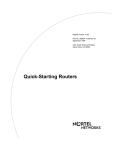
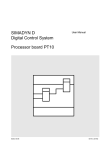
[0027] Referring to FIG. 2, each semiconductor Wafer 12
different cells on the IC Without damage to the IC or the rest
spaced apart by a distance or multiples of the distance, delta
of the semiconductor Wafer from the probe needles. By
automating the testing process With the IC, testing is done
distance, delta Y133.
faster and components Within the ICs are also tested.
DESCRIPTION OF THE DRAWINGS
[0012]
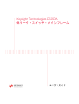
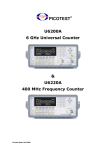
FIG. 1 is a functional diagram of a test system.
[0013]
FIG. 2 is a top vieW of a semiconductor Wafer
shoWing a matrix of integrated circuits (IC).
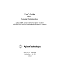
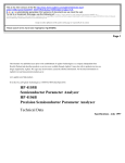
[0014]
FIG. 3 is a top vieW of the IC With a matrix of cells.
[0015]
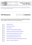
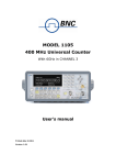
FIG. 4 is angle vieW of a probe card on the IC.
[0016]
FIG. 5 is How diagram for a process for testing ICs.
[0017]
FIG. 6 is a screenshot of a toolbar.
[0018]
FIG. 7 is a screenshot of a manual control user
interface.
[0019] FIG. 8 is a screenshot shoWing a virtual semicon
ductor Wafer map interface.
[0020]
FIG. 9A is a screenshot of the toolbar shoWing a
set of submenus a Product menu.
[0021]
FIG. 9B is a screenshot of a toolbar shoWing the
menus under a Mapping menu.
includes the matrix of ICs 11. The matrix of ICs 11 are
X131 and a second distance or multiples of the second
[0028]
Referring to FIG. 3, each IC 44 includes cells 32
in roWs 36a and 36b. Cells 32 are subcomponents of IC 44,
Which are electrical structures such as capacitors, memory
cells, etc. Each of the cells 32 has tWo bond pads 34, each
electrically connected to cell 32. Bond pads 34 are spaced
apart by a distance, delta X235, and a second distance, delta
Y237.
[0029] Referring to FIG. 4, during electrical measure
ments, probe card 20 With probe needles 40 is placed in
contact With bond pads 34 so that one probe needle is in
contact With one pad 34. Electrical signals received from test
instruments 13 are sent to probe card 20 to each IC 44 via
bond pads 34. After probe card 20 tests one set of pads in IC
44, computer 23 sends commands to probe station 28 to
move chuck 30 holding semiconductor Wafer 12 in a nega
tive Z-direction so that semiconductor Wafer 12 and the
matrix of ICs 11 move doWn and aWay from probe needles
40. In addition, computer 23 sends commands to probe
station 28 to move chuck 30 in the x-y plane. Computer 23
then moves chuck 30 in an upWard or a positive Z-direction
so that probe needles 40 are in contact With a neW set of bond
pads 34 so that neW electrical measurements may be taken.
Output Name submenu.
[0030] Referring to FIG. 5, a process 50 to test the matrix
of ICs 11 using GUI 26 is shoWn. GUI 26 alloWs the user
[0023]
(not shoWn) to provide inputs to test system 10 through
[0022]
FIG. 10 is a screen shot of a toolbar shoWing an
FIG. 11 is a screenshot of the virtual semiconduc
tor Wafer map and the GUI for silicon band gap measure
ment.
present the data graphically to the user using GUI 26.
[0024] FIG. 12 is a block diagram of a computer system
on Which the process of FIG. 5 may be implemented.
DETAILED DESCRIPTION
[0025]
menu driven commands. These user inputs alloW test system
10 to record electrical measurements of each IC 44 and to
Referring to FIG. 1, a test system 10 for measuring
the electrical characteristics of a matrix of integrated circuit
(IC) 11 on a semiconductor Wafer 12 includes, for example,
a set of instruments 13, Which include a parametric analyZer
14, a matrix sWitch 16, and a pulse generator 18. Parametric
analyZer 14 performs a parametric analysis in Which all
design variables, except one, are held constant. As an
independent or “free” variable is systematically altered, a
user evaluates the changes to the test using some kind of
measure of merit. Matrix sWitch 16 provides a sWitch to
channel the input signals received in test system 10 and
routes the signals to various output ports that are ultimately
connected to the matrix of ICs 11. Pulse generator 18
provides pulsed signals to test system 10.
[0026] Test system 10 also includes a probe card 20 that is
connected to matrix sWitch 16 by electrical coaxial 21. Via
the interface cable 22, a computer 23 With a mouse 24, a
monitor 25 and a graphical user interface (GUI) 26, controls
a probe station 28 having a vacuum chuck 30 that holds
semiconductor Wafer 12, and the set of instruments 13.
Probe card 20 is ?xed With screWs to probe station 28. More
speci?cally, a user (not shoWn), utiliZing GUI 26 controls the
movements of chuck 30 and moves semiconductor Wafer 12
[0031] Process 50 initialiZes (52) test instruments 13 by
sending a signal from computer 23 through interface cable
22 to each of the instruments. Process 50 checks (54) test
instruments 13 to ensure each are properly connected to
interface cable 22. If a bad connection exists, a Warning
message is displayed (55) on monitor 25 informing the user
of the lack of proper connections and process 50 reinitialiZes
(52) the test instruments.
[0032]
If the connections are good, process 50 reads (56)
the user’s inputs to determine if the test Will be in a manual
mode or an automatic mode. If the user makes no inputs,
process 50 defaults to the automatic mode.
[0033] Referring to FIGS. 6 and 7, in the manual mode,
process 50 receives (58) user manual control inputs. The
user manually places probe needles 40 in contact With bond
pads 34. The user selects a toolbar command by moving the
mouse cursor and clicking-on a “Mapping” menu 82 and
then selecting “manual control”84 from the “Mapping”
menu in turn brings up a manual control user interface 86.
In manual control user interface 86, the user can con?gure
test instruments 13 by controlling the parameters of each of
the instruments including, for example, voltage and current
characteristics and the timing characteristics associated With
each. Process 50 sends (59) the electrical set-up to the test
instruments 13 and displays (59) the measured results on
GUI 26.
along probe card 20 to collect electrical data from the matrix
[0034] Referring to FIG. 8, in the automatic mode, the
of ICs 11.
user has an option of selecting Which ICs 44 may be tested
Apr. 24, 2003
US 2003/0078748 A1
by selecting the speci?c ICs With mouse 24 on a virtual
semiconductor Wafer map 88 of semiconductor Wafer 12.
determines if there are any additional roWs 36 available. If
Virtual semiconductor Wafer map 88 depicts the positions of
the number of ICs left to test. If additional roWs 36 have not
the matrix of ICs 11. The user may select the entire matrix
of ICs 11 by clicking mouse 24 on a “Select All” button 89
or the user may put the mouse on individual squares 90
been tested (i.e., roW index is not equal to Zero), process 50
sends (76) commands to probe station 28 for chuck 30 to
separate from probe card 20 (i.e., probe card moves in a
representing each of the individual ICs 44 and clicking the
desired squares thus selecting the corresponding IC. Virtual
probe station 20 to move a distance delta X235 and a second
semiconductor Wafer map 88 leaves a check mark on each
not, process 50 decrements (66) IC index by one to re?ect
negative Z-direction). Process 50 sends (76) commands to
distance delta Y237 as appropriate to move probe needles 40
to a neW roW of pads 34. Process 50 also sends (76)
commands to enable test instruments 13. For example,
square selected for testing. An orientation notch 94 in virtual
map 88 corresponds to a notch normally found on semicon
ductor Wafers. A center square 92 is highlighted in a bright
process 50 triggers the pulse generator to get a package of
color (e.g., red) to orientate the user as to the center of the
virtual semiconductor Wafer map 88.
require different actions from test instruments 13. For
[0035] Referring to FIGS. 9A and 9B, in the automatic
mode, the limited user inputs includes inputting information
in a “Product” menu 96 and a “Set Home” submenu 98
under “Mapping” menu 82. For example, in “Product” menu
96, the user selects Which type of IC 44 is tested and at What
temperature the test Will be performed. By selecting “Prod
uct” menu 96, the process uses a prede?ned set of delta
X131, delta Y133, delta X235 and delta Y237 values for a
product selected and the temperature selected. The product
represents different con?gurations of IC 44. Since each
product is designed differently, these delta distances Will be
different. More importantly, due to the thermal expansion
and contraction of the ICs 44 during heat changes, these
delta distances are different by the temperature selected even
for the same product. In the automatic mode, the user must
also select “Set Home” submenu 98. By selecting “Set
Home” submenu 98, the user con?rms that probe card 20 is
positioned on semiconductor Wafer 12 and on a ?rst roW 36a
of the center IC 44 of semiconductor Wafer 12. The user can
use center square 92 and notch 94 to visually verify this.
[0036] Referring to FIG. 10, the user can also give a name
to an output ?le by selecting a “File” menu 77, selecting
“File” submenu 78 and selecting “Output Name” submenu
79. When a “Start” submenu 80 is selected by a mouse
command to commence testing, process 50 determines (60)
1,000 pulses at 1 MHZ. Different test measurements can
example, in testing capacitance, after a series of charging
and discharging of the parasitic capacitances in a cell 32,
process 50 sends a command to the parametric analyZer 14
to retrieve and record the currents. The capacitance value is
determined from the inputs and saved in the output ?le. After
test instruments 13 send and receive electrical data, process
50 decrements (66) the roW index. In this embodiment, the
number of probe needles 40 is equal to the number of pads
34 in roW 36 so that there is no need for chuck 30 to move
a delta X235 value Within roW 36.
[0040] Referring, to FIG. 11, the user is able to observe
the testing process for each test performed as the data is
collected. For example, the user can vieW virtual semicon
ductor Wafer map 87 While observing the curves on a
graphical display 100. As each IC 44 is tested GUI 26 shades
in each square 90 of virtual semiconductor Wafer display 87.
In addition, the user can read the data from a table 99 to
determine Which cell 32 in Which IC 44 is being measured.
When the test is completely performed, the user has the
capability to load the data saved in a ?le for display in table
99 and in graph 100 While also vieWing virtual map 87. A set
of graphs are sequentially displayed one after another With
a three to ?ve second delay to alloW the user to print or save
the displayed graph in a graph format ?le, or to alloW the
user to freeZe graph 100 by clicking on F10 keyboard key.
if “Product” menu 96 and “Set Home” submenu 98 received
user input. If not, a prompt WindoW indicates to the user that
action needs to be taken by the user to correct the situation.
[0041] In this embodiment, parametric analyZer 14 is a
[0037]
station 28 is a Cascade Microtech, Inc, Summit 300 mm.
Other test instruments that perform similar functions may
also be used. Interface cable 22 is a shielded General
Process 50 generates (62) the output ?le so that the
measured data collected may be stored on computer 23 and
assigns (62) an IC index to the number of ICs 44 selected for
test. In addition, a roW index is assigned indicating the
number of roWs 36 to be tested. Process 50 checks (64) to
determine that at least one IC is chosen for test. If at least one
IC is not chosen, process 50 displays (65) a prompt WindoW
Warning the user to take action.
[0038]
Process 50 decrements (66) the IC index by one.
Process 50 checks (68) to see if there are any additional ICs
44 to test by checking to see if the IC index is Zero. If the
IC index is Zero, process 50 saves (70) the last measurement
data in the ?le output ?le and closes the output ?le.
[0039]
If additional ICs 44 still need to be tested on
semiconductor Wafer 12, process 50 sends (72) commands
to test instruments 13 With assigned parameters. The dis
tance of IC 44 from the center square 92 is calculated using
delta X131 and delta Y133 values and relaying the data to
probe station 28 folloWing chuck 30 separation. The roW
index is decremented by one. Process 50 checks (74) and
HeWlett-Packard HP-4156B, matrix sWitch 16 is an Agilent
E5250A, Pulse generator 18 is an Agilent 81110A, and probe
Purpose Interface Bus (GPIB) cable manufactured by
National Instruments.
[0042] FIG. 12 shoWs a computer 23 for testing the matrix
of ICs 11 using process 50. Computer 23 includes a storage
medium 101 (e.g., hard disk), a processor 105, and interface
card 106, a memory 109, and GUI 26 for testing the matrix
of ICs 11 and the corresponding cells 32 in FIGS. 2 and 3.
Storage medium 101 stores operating system 103, data 104,
and computer instructions 102 Which are executed by pro
cessor 105 out of memory 109 to perform process 50.
Interface card 106 ensures the communication betWeen
computer 23 and the set of instruments 13 and probe station
28 via GPIB cable 22. In this embodiment, interface card
106 is a peripheral component interconnect (PCI)-GPIB card
manufactured by National Instruments.
[0043]
In this embodiment, the softWare program is Writ
ten in Microsoft Visual Basic 6.0. Process 50 is not limited
Apr. 24, 2003
US 2003/0078748 A1
to use With the hardware and software of FIG. 12 it may ?nd
2. The system of claim 1 Wherein a user selects a test
applicability in any computing or processing environment
and With any type of machine that is capable of running a
computer program. Process 50 may be implemented in
con?guration by interfacing the matrix sWitch through the
hardWare, softWare, or a combination of the tWo. Process 50
may be implemented in computer programs executed on
programmable computers/machines that each include a pro
cessor, a storage medium/article readable by the processor
(including volatile and non-volatile memory and/or storage
elements), at least one input device, and one or more output
devices. Program code may be applied to data entered using
an input device to perform process 50 and to generate output
information.
[0044] Each such program may be implemented in a high
level procedural or objected-oriented programming lan
guage to communicate With a computer system. HoWever,
the programs can be implemented in assembly or machine
language. The language may be a compiled or an interpreted
language. Each computer program may be stored on a
storage medium (article) or device (e.g., CD-ROM, hard
disk, or magnetic diskette) that is readable by a general or
special purpose programmable computer for con?guring and
operating the computer When the storage medium or device
is read by the computer to perform process 50. Process 50
may also be implemented as a machine-readable storage
GUI.
3. The system of claim 2 Wherein the user selects either an
automatic test mode or a manual test mode of the semicon
ductor Wafer, the automatic test modes alloWs the user to
select devices for testing.
4. The system of claim 3 Wherein the manual test mode
includes the user setting the electrical signals of the test
instruments through the GUI.
5. The system of claim 4 Wherein the probe card transmits
a set of electrical signals from each test instrument through
the probe needles to each set of bond pads and generating a
test result for each device that is displayed graphically on the
display.
6. The system of claim 5 Wherein the test instruments
include:
a pulse generator; and
a parametric analyZer.
7. The system of claim 1 Wherein the testing includes
measuring a silicon band gap voltage.
8. The system of claim 1 Wherein the testing includes
measuring a capacitance.
9. A method, comprising:
medium, con?gured With a computer program, Where upon
execution, instructions in the computer program cause the
computer to operate in accordance With process 50.
selecting a test con?guration through a graphical user
[0045] The invention is not limited to the speci?c embodi
ments described herein. For example, the invention can be
used to move any probe card along any surface. Other I/O
measuring a set of electrical characteristics of each of a
plurality of devices on a semiconductor Wafer selected
interfaces can be used instead of mouse 24 (e.g., a keyboard,
trackball, input tablet, joystick). The invention is also not
limited to testing ICs on semiconductor Wafers, but on ICs
detached from the semiconductor Wafer. The invention is not
limited to the speci?c processing order of FIG. 5. Rather, the
blocks of FIG. 5 may be re-ordered, as necessary, to achieve
the results set forth above.
[0046]
Other embodiments not described here are also
Within the scope of the folloWing claims.
What is claimed is:
1. A system, comprising:
a graphical user interface (GUI) connected to an input/
output device of a computer system;
one or more test instruments producing a set of electrical
signals;
a probe card having a plurality of probe needles used for
measuring electronic characteristics of each of a plu
rality of devices on a semiconductor Wafer, each device
having a plurality of cells, each cell having a set of
bond pads;
a matrix sWitch; and
an interface conduit electrically connecting the one or
interface (GUI) connected to an input/output (I/O)
device of a computer; and
for testing, the probe card having a plurality of probe
needles, each device having a plurality of cells, each
cell having a set of bond pads, the semiconductor Wafer
moving so that the probe needles measure the electrical
characteristics of each cell for each device selected for
testing.
10. The method of claim 9, further comprising sending a
signal to activate a plurality of test instruments.
11. The method of claim 10, further comprising deter
mining if the plurality of test instruments are electrically
connected.
12. The method of claim 11, further comprising designat
ing if testing is an automatic test mode or a manual test
mode, the automatic test mode includes selecting devices on
a semiconductor Wafer for testing, the manual test mode
includes the user setting the electrical signals of the test
instruments through the GUI.
13. The method of claim 12, generating an output ?le for
all devices tested.
14. The method of claim 13, further comprising graphing
data in the output ?le on a display.
15. The method of claim 14 Wherein the plurality of test
instruments include:
a pulse generator; and
a parametric analyZer.
16. The method of claim 1 Wherein the testing includes
measuring a silicon band gap voltage.
17. The method of claim 1 Wherein the testing includes
more test instruments, the computer, the probe card,
and the matrix sWitch together, the semiconductor
measuring a capacitance.
Wafer moving so that the probe needles measure the
electrical characteristics of each cell for each device
Wafer using a graphical interface (GUI) comprising:
selected for testing.
18. An apparatus for testing devices on a semiconductor
a memory that stores executable instructions; and
Apr. 24, 2003
US 2003/0078748 A1
a processor that executes the instructions to:
select a test con?guration using the GUI; and
measure a set of electrical characteristics of each device
selected for testing, the probe card having a plurality
of probe needles, each device having a plurality of
cells, each cell having a set of bond pads, the
semiconductor Wafer moving so that the probe
needles measure the electrical characteristics of each
cell for each device selected for testing.
19. The apparatus of claim 18, further comprising instruc
tions that cause the machine to send a signal to activate a
plurality of test instruments.
20. The apparatus of claim 19, further comprising instruc
tions that cause the machine to determine if the plurality of
test instruments are electrically connected.
21. The apparatus of claim 20, further comprising instruc
measure a set of electrical characteristics of each device
selected for testing, the probe card having a plurality of
probe needles, each device having a plurality of cells,
each cell having a set of bond pads, the semiconductor
Wafer moving so that the probe needles measure the
electrical characteristics of each cell for each device
selected for testing.
26. The article of claim 25, further comprising instruc
tions that cause the machine to send a signal to activate a
plurality of test instruments.
27. The article of claim 26, further comprising instruc
tions that cause the machine to determine if the plurality of
test instruments are electrically connected.
28. The article of claim 27, further comprising instruc
tions that cause the machine to designate if testing is an
automatic test mode or a manual test mode, the automatic
test mode includes selecting devices on a semiconductor
tions that cause the machine to designate if testing is an
Wafer for testing, the manual test mode includes the user
automatic test mode or a manual test mode, the automatic
test includes selecting devices on a semiconductor Wafer for
the GUI.
testing, the manual test mode includes the user setting the
electrical signals of the test instruments through the GUI.
22. The apparatus of claim 21, further comprising instruc
tions that cause the machine to:
generate data in an output ?le for all devices tested; and
graph data in the output ?le on a display.
23. The apparatus of claim 18 Wherein the testing includes
measuring a silicon band gap voltage.
24. The apparatus of claim 18 Wherein the testing includes
measuring a capacitance.
25. An article comprising a machine-readable medium
that stores executable instructions for testing devices on a
semiconductor Wafer, the instructions causing a machine to:
select a test con?guration using a graphical user interface
(GUI); and
setting the electrical signals of the test instruments through
29. The article of claim 28, further comprising instruc
tions that cause the machine to:
generate data in an output ?le for all devices tested; and
graph data in the output ?le on a display.
30. The article of claim 29 Wherein the plurality of test
instruments include:
a pulse generator; and
a parametric analyZer.
31. The
measuring
32. The
measuring
article of claim 25 Wherein the testing includes
a silicon band gap voltage.
article of claim 25 Wherein the testing includes
a capacitance.