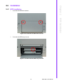
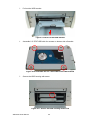
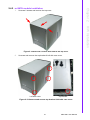
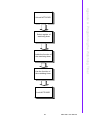
1
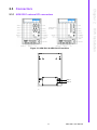
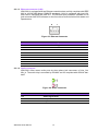
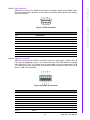
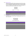
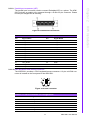
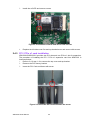
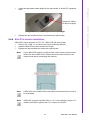
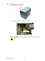
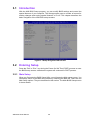
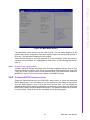
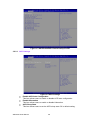
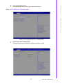
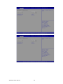
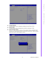
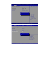
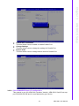
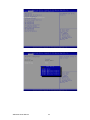
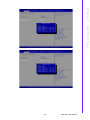
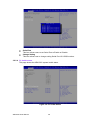
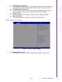
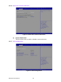
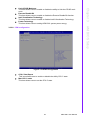
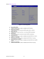
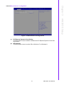
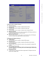
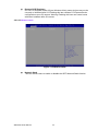
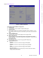
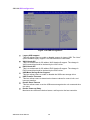
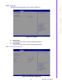
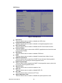
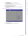
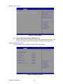
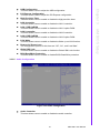
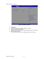
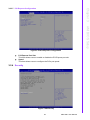
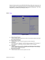
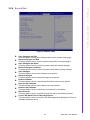
User Manual ARK-5261 Embedded IPC Attention! Please note: This package contains a hard-copy user manual in Chinese for China CCC certification purposes, and there is an English user manual included as a PDF file on the CD. Please disregard the Chinese hard copy user manual if the product is not to be sold and/or installed in China. ARK-5261 User Manual ii Copyright The documentation and the software included with this product are copyrighted 2015 by Advantech Co., Ltd. All rights are reserved. Advantech Co., Ltd. reserves the right to make improvements in the products described in this manual at any time without notice. No part of this manual may be reproduced, copied, translated or transmitted in any form or by any means without the prior written permission of Advantech Co., Ltd. Information provided in this manual is intended to be accurate and reliable. However, Advantech Co., Ltd. assumes no responsibility for its use, nor for any infringements of the rights of third parties, which may result from its use. Acknowledgements Award is a trademark of Award Software International, Inc. VIA is a trademark of VIA Technologies, Inc. IBM, PC/AT, PS/2 and VGA are trademarks of International Business Machines Corporation. Intel® and Pentium® are trademarks of Intel Corporation. Microsoft Windows® is a registered trademark of Microsoft Corp. RTL is a trademark of Realtek Semi-Conductor Co., Ltd. ESS is a trademark of ESS Technology, Inc. UMC is a trademark of United Microelectronics Corporation. SMI is a trademark of Silicon Motion, Inc. Creative is a trademark of Creative Technology LTD. CHRONTEL is a trademark of Chrontel Inc. Nuvoton is a trademark of Nuvoton Technology Corporation. All other product names or trademarks are properties of their respective owners. For more information about this and other Advantech products, please visit our website at: http://www.advantech.com/ http://www.advantech.com/ePlatform/ For technical support and service, please visit our support website at: http://support.advantech.com.tw/support/ Part No. 2001526101 Edition 2 Printed in China May 2015 iii ARK-5261 User Manual Product Warranty (2 years) Advantech warrants to you, the original purchaser, that each of its products will be free from defects in materials and workmanship for two years from the date of purchase. This warranty does not apply to any products which have been repaired or altered by persons other than repair personnel authorized by Advantech, or which have been subject to misuse, abuse, accident or improper installation. Advantech assumes no liability under the terms of this warranty as a consequence of such events. Because of Advantech’s high quality-control standards and rigorous testing, most of our customers never need to use our repair service. If an Advantech product is defective, it will be repaired or replaced at no charge during the warranty period. For outof-warranty repairs, you will be billed according to the cost of replacement materials, service time and freight. Please consult your dealer for more details. If you think you have a defective product, follow these steps: 1. Collect all the information about the problem encountered. (For example, CPU speed, Advantech products used, other hardware and software used, etc.) Note anything abnormal and list any onscreen messages you get when the problem occurs. 2. Call your dealer and describe the problem. Please have your manual, product, and any helpful information readily available. 3. If your product is diagnosed as defective, obtain an RMA (return merchandise authorization) number from your dealer. This allows us to process your return more quickly. 4. Carefully pack the defective product, a fully-completed Repair and Replacement Order Card and a photocopy proof of purchase date (such as your sales receipt) in a shippable container. A product returned without proof of the purchase date is not eligible for warranty service. 5. Write the RMA number visibly on the outside of the package and ship it prepaid to your dealer. Declaration of Conformity FCC Class A Note: This equipment has been tested and found to comply with the limits for a Class A digital device, pursuant to part 15 of the FCC Rules. These limits are designed to provide reasonable protection against harmful interference when the equipment is operated in a commercial environment. This equipment generates, uses, and can radiate radio frequency energy and, if not installed and used in accordance with the instruction manual, may cause harmful interference to radio communications. Operation of this equipment in a residential area is likely to cause harmful interference in which case the user will be required to correct the interference at his own expense. ARK-5261 User Manual iv Technical Support and Assistance 1. 2. Visit the Advantech web site at www.advantech.com/support where you can find the latest information about the product. Contact your distributor, sales representative, or Advantech's customer service center for technical support if you need additional assistance. Please have the following information ready before you call: – Product name and serial number – Description of your peripheral attachments – Description of your software (operating system, version, application software, etc.) – A complete description of the problem – The exact wording of any error messages Warnings, Cautions and Notes Warning! Warnings indicate conditions, which if not observed, can cause personal injury! Caution! Cautions are included to help you avoid damaging hardware or losing data. e.g. There is a danger of a new battery exploding if it is incorrectly installed. Do not attempt to recharge, force open, or heat the battery. Replace the battery only with the same or equivalent type recommended by the manufacturer. Discard used batteries according to the manufacturer's instructions. Note! Notes provide optional additional information. v ARK-5261 User Manual Safety Instructions 1. 2. 3. Please read these safety instructions carefully. Please keep this User’s Manual for later reference. Please disconnect this equipment from AC outlet before cleaning. Use a damp cloth. Don’t use liquid or sprayed detergent for cleaning. Use moist sheet or cloth for cleaning. 4. For pluggable equipment, the socket-outlet shall near the equipment and shall be easily accessible. 5. Please keep this equipment from humidity. 6. Lay this equipment on a reliable surface when installing. A drop or fall could cause injury. 7. The openings on the enclosure are for air convection hence protecting the equipment from overheating. DO NOT COVER THE OPENINGS. 8. Make sure the voltage of the power source when connecting the equipment to the power outlet. 9. Place the power cord such a way that people cannot step on it. Do not place anything over the power cord. 10. All cautions and warnings on the equipment should be noted. 11. If the equipment is not used for long time, disconnect the equipment from mains to avoid being damaged by transient over-voltage. 12. Never pour any liquid into ventilation openings; this could cause fire or electrical shock. 13. Never open the equipment. For safety reasons, only qualified service personnel should open the equipment. 14. If one of the following situations arises, get the equipment checked by service personnel: The power cord or plug is damaged. Liquid has penetrated into the equipment. The equipment has been exposed to moisture. The equipment does not work well, or you cannot get it to work according to the user's manual. The equipment has been dropped and damaged. The equipment has obvious signs of breakage. 15. DO NOT LEAVE THIS EQUIPMENT IN AN ENVIRONMENT WHERE THE STORAGE TEMPERATURE MAY GO BELOW -40° C (-40° F) OR ABOVE 85° C (185° F). THIS COULD DAMAGE THE EQUIPMENT. THE EQUIPMENT SHOULD BE IN A CONTROLLED ENVIRONMENT. 16. CAUTION: DANGER OF EXPLOSION IF BATTERY IS INCORRECTLY REPLACED. REPLACE ONLY WITH THE SAME OR EQUIVALENT TYPE RECOMMENDED BY THE MANUFACTURER, DISCARD USED BATTERIES ACCORDING TO THE MANUFACTURER'S INSTRUCTIONS. 17. The sound pressure level at the operator's position according to IEC 704-1:1982 is no more than 70 dB (A). 18. RESTRICTED ACCESS AREA: The equipment should only be installed in a Restricted Access Area. DISCLAIMER: This set of instructions is given according to IEC 704-1. Advantech disclaims all responsibility for the accuracy of any statements contained herein. ARK-5261 User Manual vi Packing List Before installation, please ensure the following items have been shipped: 1 x ARK-5261 unit 1 x Driver/Utility CD 1 x Registration and 2 years Warranty card 1x DB37 to 4x DB9 transfer cable (Only for Isolation version) Ordering Information Model Number Description ARK-5261S Series ARK-5261S-J0A1E Intel Celeron J1900 2 GHz, On-board 4Gb Memory, VGA, 2xGbE, 6xUSB ports, 4xCOM ports, audio, PCIex1 and 2xPCI expansion slots, 9V~30V DC power with 2pin Phonenix connector ARK-5261I Series ARK-5261I-J0A1E Intel Celeron J1900 2 GHz, On-board 4Gb Memory,VGA, 2xGbE, 6xUSB ports, 4x Isolation COM port, audio, PCIex1 and 2xPCI expansion slots, 9V~30V DC power with 2pin Phonenix connector ARK-5261P Series ARK-5261P-J0A1E Intel Celeron J1900 2GHz, On-board 4Gb Memory, VGA, 2xGbE, 5xUSB port, 4xCOM ports, audio, 3xPCI and 1xMini-PCIe expansion slot, 9~30V DC power with 2pin Phonenix connector Optional Accessories Part Number Description 1757003659 AC-to-DC Adapter, DC19 V/3.42 A 65 W, with Phoenix Power Plug 1700060202 PS/2 Keyboard/Mouse cable 1700001947 Power cable 2-pin 180 cm, USA 1700001948 Power cable 2-pin 180 cm, Europe 1700001949 Power cable 2-pin 180 cm, UK 1700021831-01 DP to DVI-D cable w/BKT PCA-TPM-00A1E TPM Module vii ARK-5261 User Manual ARK-5261 User Manual viii Chapter 1 1 General Introduction This chapter gives background information on ARK-5261. 1.1 Introduction ARK-5261 is a powerful, robust and fanless Embedded Box Computer. All electronic components are protected in a compact, sealed, aluminum case for easy embedding in the customer’s own housing, or as a stand-alone application where the environment is harsh. The ARK-5261 can be used as a standalone system or wall-mounted. The system accepts a wide range of DC power in and comes in a footprint of 137 x 189 x 221 mm. The rugged cast aluminum case not only provides great protection from EMI, shock/vibration, cold and heat, but, as we mentioned before, passive cooling for quiet fanless operation. The ARK-5261 is equipped with Intel® Celeron® Processor J1900 at 2GHz (up to 2.41 GHz), and 4 cores, making it highly suitable for embedded and industrial PC applications requiring high processor performance within a limited space. Featuring two PCI and one PCIe x1 slots or 3 PCI and one Mini-PCIE slot by ARK-5261P SKU., ARK-5261 also carries one USB3.0 and four USB2.0 and two gigabit LAN ports. It can support up to 8 GB DDR3L (low power DDR3) SDRAM of main memory and two easily maintained 2.5” SATA HDD. ARK-5261 offers four serial ports, and can support RS-232/422/485 by BIOS setting and COM1 & COM 2 supports 5V& 12V power inputs. For COM function, ARK-5261 also supports a isolation version that supports 4 x RS-422/485. ARK-5261 is ideal for embedded system applications such as machine automation, and industrial plant and cabinet integration. 1.2 Product Features 1.2.1 General CPU: Intel Celeron Processor J1900 at 2 GHz BIOS: AMI 16 M-bit Flash BIOS System Memory: Dual 204-pin SO-DIMM DDR3L-1333 MHz up to 8GB HDD: Support 2 drive bays space for SATA 2.5" HHD/SSD mSATA: Supports 1 x mSATA by mini-PCIE slot (shared with SATA II) Watchdog Timer: Single chip Watchdog 255-level interval timer, setup by software I/O Interface: 4 x RS-233/422/485, COM 1 & COM 2 with 5V/12V power, support Auto-flow control USB: 1 x USB3.0; 4 x USB 2.0 and 1 x Internal USB 2.0 (ARK-5261P series does not support type A USB connector) Audio: High Definition Audio (HD), Line-out, Mic-in DIO: 8-bit general purpose input/output (DB9 Connector) Expansion Interface: Supports maximum 15W power for each expansion slot Mini-PCIe: Only ARK-5261P series support Mini-PCIe slot m-SATA: ARK-5261 series supports m-SATA by Mini-PCIe socket Note! When the system has mSATA installed via mini-PCIe socket, SATAII will not function. ARK-5261 User Manual 2 Chipset: Chipset integrated Intel HD Graphic Memory Size: Up to 224 MB of dynamic video memory allocation Resolution: – VGA: Supports up to 2560 x 1600 @ 60 Hz 1.2.3 Ethernet 1.3 Chipset 1.3.1 Functional specification 1.3.1.1 Processor Processor Intel® Celeron® Processor J1900 at 2GHz with 2M Cache, up to 2.41 GHz Manufacturing Technology: 22nm 1.3.1.2 Chipset Memory Intel® Celeron® Processor J1900 Support DDR3L-1333 MHz (1.35V) up to 8GB SODIMM Socket: – 204-pin SO-DIMM sockets*2 Graphic and Video Controllers Chipset integrated Intel HD Graphic Supports Intel® Quick Sync Video Supports Intel® Virtualization Technology (VT-x) Supports Intel® 64 Supports Enhanced Intel SpeedStep® Technology VGA: supports resolution up to 2560 x 1600 @ 60Hz VGA Connector on board: D-SUB 15P SATA Interface SOC: Intel Bay trail J1900 Two (2) SATA Revision 2.0 ports (eSATA capable) Legacy IED (including IRQ)/Native IDE/AHCI appearance to OS Partial/ Slumber power management modes with wake Capable of 3Gbit/s transfer rate Audio Link SOC: Intel Bay trail J1900 Supports HD Codec Supports Link for Audio and Telephony CODECS 3 ARK-5261 User Manual General Introduction Chipset: – LAN1:Intel I211 – LAN2: Intel I211 Speed: 10/100/1000 Mbps Interface: 2 x RJ45 Standard: Compliant with IEEE 802.3, IEEE 802.3u, IEEE 802.ab. Chapter 1 1.2.2 Display USB Interface SOC: Intel Bay trail J1900 USB host interface with support for 1 USB3.0 port and 5 USB2.0 ports Supports high-speed, full-speed, and low-speed capable Supports legacy keyboard/mouse software Power Management SOC: Intel Bay trail J1900 Supports ACPI 5.0 ACPI Power Management Logic Support Power connector: Plug-In block 2P x 1 BIOS AMI 16Mb Flash BIOS via SPI 1.3.1.3 Others Serial ports Nuvoton NCT6106D support Up to 4 serial ports by Nuvoton NCT6106D support High Speed NS16C550A compatible UARTs with data rates to 1.5 Mbps Supports IRQ sharing among serial ports on XPE COM1 ~ COM4: Supports to RS-232/422/485 and setting by BIOS setting COM1 ~ COM4: RS-485 supports auto flow control COM 1~ COM 2: Supports 5V/12V power and setting by jumper (Default setting is no power) COM connector: D-SUB CON. 9P COM 1 ~ COM4: Supports RS-232/422/485 with auto-flow control and setting by BIOS ESD Protection: 15Kv Serial ports Surge production: 2Kv (Isolation Ports) Electrical Isolation: 2Kv COM connector: D-SUB CON. 37P with transfer cable LAN LAN 1 Intel I211, LAN2 Intel I211 Compliant with IEEE 802.3, IEEE 802.3u, IEEE 802.ab. Supports 10/100/1000 Mbps Supports Wake on LAN Audio Audio Codec: Realtek ACL892: Compliant with HD Audio specifications Supports to 16/20/24-bit DAC and 16/20/24-bit ADC resolution Support: Line-out, Mic-in DAC supports 16/20/24-bit PCM format, multiple stereo recording DIO Nuvoton NCT6106D support 10 I/O pins with one 5 V power ping and one ground pin 5 V tolerance I/Os. DIO Connectors: 9 pins DSUB connector Battery backup ARK-5261 User Manual BR2032 3 V/190mAh 4 Chapter 1 1.4 Mechanical Specifications 1.4.1 Dimensions 137.0 [5.39] x 189.0 [7.44] x 221.0 [8.70] Unit: mm [Inch] 137 240.97 90 234.07 5 General Introduction 189 215 234 11 90 5 221 120 Figure 1.1 ARK-5261 Mechanical Dimension Drawing 137 240.97 90 234.07 5 189 215 234 11 90 5 221 120 Figure 1.2 ARK-5261I Mechanical Dimension Drawing 1.4.2 Weight 4.2 kg (9.24 lbs) 5 ARK-5261 User Manual 1.5 Power Requirements 1.5.1 System power Minimum power input: DC 9V(-5%) ~ 30V(+10%), 6.6A~2A Caution! ARK-5261 total power consumption should not exceed 45W when DCIN voltage is under 10V. 1.5.2 RTC battery BR2032 3 V/190 mAh 1.6 Environment Specification 1.6.1 Operating temperature -20 ~ 60 °C with 0.7m/sec air flow: with 2 x Industrial SSD without PC expansion boards 1.6.2 System safety certification test temperature 0 ~ 50° C with 2.5” HDD 1.6.3 Relative humidity 95% @ 40 °C (non-condensing) 1.6.4 Storage temperature -40 ~ 85 °C (-40 ~ 185 °F) 1.6.5 Vibration during operation When system is equipped with SSD only: 5 Grms, IEC 60068-2-64, random, 5 ~ 500 Hz, 1 Oct/min., 1 hr/axis, x,y,z 3 axes. When system is equipped with 2.5-inch HDD: 1 Grms, IEC 60068-2-64, random, 5 ~ 500 Hz, 1 Oct/min., 1 hr/axis, x,y,z 3 axes. 1.6.6 Shock during operation When system is equipped with Compact Flash card only: 50 G, IEC 60068-2-27, half sine, 11 ms duration. When system is equipped with 2.5-inch: 20 G, IEC 60068-2-27, half sine, 11 ms duration. 1.6.7 Safety CCC, BSMI 1.6.8 EMC CE, FCC, CCC, BSMI ARK-5261 User Manual 6 Chapter 2 2 H/W Installation This chapter introduces external IO and the installation of ARK-5261 hardware. 2.1 Introduction The following sections show the internal jumper settings and the external connectors and pins assignment for applications. 2.2 Jumpers 2.2.1 Jumper description You may configure the ARK-5261 to match the needs of your application by setting jumpers. A jumper is a metal bridge used to close an electric circuit. It consists of two metal pins and a small metal clip (often protected by a plastic cover) that slides over the pins to connect them. To close a jumper, you connect the pins with the clip. To open a jumper, you remove the clip. Sometimes a jumper will have three pins, labeled 1, 2 and 3. In this case you would connect either pins 1 and 2, or 2 and 3. open closed closed 2-3 The jumper settings are schematically depicted in this manual as follows. 1 2 open 1 2 closed closed 2-3 A pair of needle-nose pliers may be helpful when working with jumpers. If you have any doubts about the best hardware configuration for your application, contact your local distributor or sales representative before you make any changes. Generally, you simply need a standard cable to make most connections. ARK-5261 User Manual 8 Chapter 2 2.2.2 Jumper list Table 2.1: Jumper List Label Function JCMOS1 Clear CMOS JCOMPWR1/JCOMPWR2 COM1 & COM2 power 5V & 12V option System AT/ATX mode option JIMINIPCIE1 Setting PCIE design agreement for Mini-PCIE 1.1 or 1.2 SWA1 Setting Power for Mini-PCIE 1.1 or 1.2 2.2.2.1 Clear CMOS ARK-5261 single board computer contains a jumper that can erase CMOS data and reset the system BIOS information. Normally this jumper should be set with pins 1-2 closed. If you want to reset the CMOS data, set CMOS1 to 2-3 closed for just a few seconds, and then move the jumper back to 1-2 closed. This procedure will reset the CMOS to its default setting. CMOS1 Clear CMOS Footprint 3x1 Pin Setting Function (1-2) Normal (default) (2-3) Clear CMOS 2.2.2.2 COM power function option ARK-5261 Supports COM1 & COM2 with power, the default is not power (RI). If you want to option COM 1 or COM 2 power, you should make sure your device power specification first. JCOMPWR1/JCOMPWR2 COM1 & COM2 Power Option FootPrint 3x2 Pin Setting Function (4-6) RI (Default No Power) (3-4) 5V Power (4-6) 12V Power 9 ARK-5261 User Manual H/W Installation PSON1 2.2.2.3 System AT/ATX module function option ARK-5261 support AT or ATX module and Default is ATX module. if you want to change to AT module that you can find AT/ATX module jumper in backplane. PSON1 System AT/ATX module option FootPrint 3x1 Pin Setting Function (1-2) AT module (2-3) ATX module 2.2.2.4 Mini-PCIE 1.1 or 1.2 power setting (only for ARK-5261P-J0A1E series) ARK-5261 supports PCIE design agreement both Mini-PCIE 1.1 & 1.2 that design differences is in standby power. If your Mini-PCIE doesn't work, please confirm MiniPCIE specification that you are using. JMINIPCI1 Mini-PCIE 1.1 & 1.2 option Foot Print 3x1 Pin Setting Function (1-2) Mini-PCIE 1.2 (for +V3.3 SB) (2-3) Mini-PCIE 1.1 (for +V2.2) There has two Jumpers to setting Mini-PCIE 1.1 or 1.2, you must be setting two jumpers together. Please check jumper setting drawing as below: ARK-5261 User Manual 10 Chapter 2 2.3 Connectors 2.3.1 ARK-5261 external I/O connectors HDD 1 HDD 2 Figure 2.2 ARK-5261 Rear View 11 ARK-5261 User Manual H/W Installation Figure 2.1 ARK-5261 & ARK-5261I Front View 2.3.1.1 COM connector ARK-5261 provides four D-sub 9-pin connectors, which offers RS-232/422/485 serial communication interface ports. Default setting is RS-232, if you want to use RS-422/ 485, you can change the mode in BIOS setting. You can find detailed setting methods in Chapter 3. Table 2.2: COM Connector Pin Assignments RS-232 RS-422 RS-485 Pin Signal Name Signal Name Signal Name 1 DCD Tx- DATA- 2 RxD Tx+ DATA+ 3 TxD Rx+ NC 4 DTR Rx- NC 5 GND GND GND 6 DSR NC NC 7 RTS NC NC 8 CTS NC NC 9 RI NC NC Note! NC represents “No Connection”. ARK-5261 User Manual 12 Pin 1 NC Pin 20 NC Pin 2 COM 1_422/485 TX- Pin 21 COM 1_422RX- Pin 3 COM1_GND Pin 22 NC Pin 4 NC Pin 23 NC Pin 5 COM 1_422/485 TX+ Pin 24 COM 1_422RX+ Pin 6 NC Pin 25 COM 2_422/485 TX- Pin 7 COM 2_422RX- Pin 26 COM2_GND Pin 8 NC Pin 27 NC Pin 9 NC Pin 28 COM 2_422/485 TX+ Pin 10 COM 2_422RX+ Pin 29 NC Pin 11 COM 3_422/485 TX- Pin 30 COM 3_422RX- Pin 12 COM 3_GND Pin 31 NC Pin 13 NC Pin 32 NC Pin 14 COM 3_422/485 TX- Pin 33 COM 3_422RX- Pin 15 NC Pin 34 COM 4_422/485 TX- Pin 16 COM 4_422RX- Pin 35 COM4_GND Pin 17 NC Pin 36 NC Pin 18 NC Pin 37 COM 4_422/485 TX+ Pin 19 COM 4_422RX+ 13 ARK-5261 User Manual H/W Installation Table 2.3: Isolation COM Connector Pin Assignments Chapter 2 2.3.1.2 Isolation COM connector (supports Isolation version) ARK-5261 Isolation version provides four RS-422/485 isolation serial communication interface ports, transferred from DB37 connector to the DB9 connector. 2.3.1.3 Ethernet connector (LAN) ARK-5261 is equipped with two Ethernet controllers that are fully compliant with IEEE 802.3u 10/100/1000 Mbps CSMA/CD standards. LAN1 is equipped with Intel I211 and LAN2 is equipped with Intel I211. The Ethernet port provides a standard RJ-45 jack connector with LED indicators on the front side to show its Active/Link status and Speed status. 8 1 Figure 2.3 Ethernet Connector Table 2.4: Ethernet Connector Pin Assignments Pin 10/100/1000BaseT Signal Name 1 TX+ 2 TX- 3 RX+ 4 MDI2+ 5 MDI2- 6 RX- 7 MDI3+ 8 MDI3- 2.3.1.4 Audio connector ARK-5261 offers stereo audio ports by three phone jack connectors of Line_Out, Mic_In. The audio chip is controlled by ACL892, and it’s compliant with AZALIA standard. Figure 2.4 Audio Connector Table 2.5: Audio Connector Pin Assignments Pin Audio Signal Name 1 Line_Out 2 Mic_In ARK-5261 User Manual 14 1 2 3 4 5 Chapter 2 2.3.1.5 DIO connector ARK-5261 provides one DSUB 9-pin female connector, which offers Digital Input/ Output communication interface. If users want to use DIO, please find the Pin assignment as following. 6 7 8 9 H/W Installation Figure 2.5 DIO Connector Table 2.6: DIO Connector Pin Assignments Pin Signal Name 1 DIO bit0 2 DIO bit1 3 DIO bit2 4 DIO bit3 5 VCC 6 DIO bit4 7 DIO bit5 8 DIO bit6 9 DIO bit7 2.3.1.6 USB 3.0 connector ARK-5261 provides one USB 3.0 interface connector, which gives complete Plug & Play and hot swapping for up to 127 external devices. The USB interface complies with USB XHCI, Rev. 3.0. Please refer to below table for its pin assignments. USB 3.0 connectors contain legacy pins to interface to USB 2.0 devices, and a new set of pins for USB 3.0 connectivity. Figure 2.6 USB 3.0 Connector Table 2.7: USB 3.0 Connector Pin Assignment Pin 1 +5V Pin 2 USB Data - Pin 3 USB Data + Pin 4 GND Pin 5 SSRX- Pin 6 SSRX+ Pin 7 GND Pin 8 SSTX- Pin 9 SSTX+ 15 ARK-5261 User Manual 2.3.1.7 USB 2.0 connector ARK-5261 provides five USB 2.0 interface connectors, 4 at front side and 1 at internal, which give complete Plug & Play and hot swapping for up to 127 external devices. The USB interface complies with USB UHCI, Rev. 2.0. Please refer to Table 2.7 for its pin assignments. The USB connectors are used to connect any device that conforms to the USB interface. Most digital devices conform to this standard. The USB interface supports Plug and Play without turning off computers. Figure 2.7 USB Connector Table 2.8: USB 2.0 Connector Pin Assignment Pin Signal name Pin Signal name 1 VCC 2 USB_data- 3 USB_data+ 4 GND 2.3.1.8 VGA connector The ARK-5261 provides a high resolution VGA interface connected by a D-sub 15pin connector to support a VGA CRT monitor. It supports display resolution of up to 2560 x 1600 @ 60 Hz. 5 10 15 1 6 11 Figure 2.8 VGA Connector Table 2.9: VGA Connector Pin Assignments Pin Signal Name Pin Signal Name 1 Red 2 Green 3 Blue 4 NC 5 GND 6 GND 7 GND 8 GND 9 NC 10 GND 11 NC 12 NC 13 H-SYNC 14 V-SYNC 15 NC ARK-5261 User Manual 16 Table 2.10: Parallel Port Connector Pin Assignments Pin Signal Name Pin Signal Name 1 PIO_STB 2 LPT_AFD# 3 PIO_PD0 4 LPT_ERR# 5 PIO_PD1 6 LPT_INIT# 7 PIO_PD2 8 LPT_SLIN# 9 PIO_PD3 10 GND 11 PIO_PD4 12 GND 13 PIO_PD5 14 GND 15 PIO_PD6 16 GND 17 PIO_PD7 18 GND 19 LPT_ACK# 20 GND 21 LPT_BUSY 22 GND 23 LPT_PE 24 GND 25 LPT_SLCT 2.3.1.10 PS/2 Keyboard and mouse connector The ARK-5261 provides a PS/2 keyboard/mouse connector. A 6-pin mini-DIN connector is located on the front panel of the ARK-5261. 6 5 4 3 2 1 Figure 2.10 PS/2 Connector Table 2.11: PS/2 Connector Pin Assignments Pin Signal Name 1 PS2_KBDAT 2 PS2_MSDAT 3 GND 4 VCC 5 PS2_KBCLK 6 PS2_MSCLK 17 ARK-5261 User Manual H/W Installation Figure 2.9 Parallel Port Connector Chapter 2 2.3.1.9 Parallel port connector (LPT) The parallel port is normally used to connect Embedded IPC to a printer. The ARK5261 includes a parallel port, accessed through a D-Sub 25-pin connector. Please find the pin assignment as following. 2.3.1.11 Power input connector ARK-5261 comes with a two pin header as default that carries 9 VDC (-5%) ~ 30 VDC (+10%) external power input. Figure 2.11 2-pins header Table 2.12: Power Connector for Pin Header Pin Assignments Pin Signal Name 1 GND 2 +9 VDC ~ 30 VDC 2.3.1.12 Power ON/OFF button ARK-5261 comes with a Power On/Off button with LED indicators on the front side to show its On status (Green LED) and Off/Suspend status (Orange LED), that support dual function of Soft Power -On/Off (Instant off or Delay 4 Second), and Suspend. Figure 2.12 Power Button 2.3.1.13 LED indicators ARK-5261 has one LED for System Storage status on front metal face. ARK-5261 User Manual 18 Chapter 2 2.4 Installation 2.4.1 HDD installation 1. Unscrew the HDD door screws. 2. Unscrew the HDD tracy's screw. Figure 2.14 Unscrew the HDD tracy's screw 19 ARK-5261 User Manual H/W Installation Figure 2.13 Unscrew the HDD door screws 3. Pull out the HDD bracket. Figure 2.15 Pull out the HDD bracket 4. Assemble 2.5' STAT HDD with four screws on bottom side of bracket. Figure 2.16 Assemble the 2.5" SATA HDD to the HDD bracket 5. Secure the HDD housing with screw. Figure 2.17 Secure the HDD housing with screw ARK-5261 User Manual 20 1. Chapter 2 2.4.2 m-SATA module installation Unscrew 2 screws and remove the top cover. H/W Installation Figure 2.18 Unscrew 2 screws and remove the top cover 2. Unscrew and remove the top bracket & left side case cover. Top Bracket Left side cover Figure 2.19 Unscrew and remove top bracket & left side case cover 21 ARK-5261 User Manual 3. Install the m-SATA and secure screws. Figure 2.20 Install the m-SATA and secure with screws 4. Replace the left side cover first and top bracket/cover and secure with screws. 2.4.3 PCI / PCIe x1 card installation ARK-5261S/ARK-5261I provides two PCI slots and one PCIe x1 slot for expansion. The procedure of installing the PCI / PCIe x1 expansion card into ARK-5261 is instructed below. 1. Refer to 2.4.2 step 1~2 to remove the top cover and top bracket. 2. Remove the PCI dummy bracket. 3. Insert the PCI Card and fasten with screw. Figure 2.21 Insert the PCI card and fasten the screw ARK-5261 User Manual 22 Adjust the depressed rubber height on the top bracket, to fit the PCI expansion card. Rotate the rubber to adjust its height 5. Replace the top bracket and top cover and secure with screws. 2.4.4 Mini-PCIe module installation ARK-5261P series supports 3 x PCI & 1 x Mini-PCIE (full size socket) 1. Refer to 2.4.2 step 1~2 to remove the top cover and top bracket. 2. Install the Mini-PCIe module and secure screws. 3. Replace the top bracket/cover and secure with screws. Note! If your Mini-PCIE module is a Wifi module, there are two antenna holes at the rear side of ARK-5261. Please remove the steel cutouts in the antenna hole before assembling the antenna. Note! If ARK-5261 uses a Wifi antenna, the wall-mount bracket will not need to be assembled. Note! ARK-5261 supports both Mini-PCIe 1.1 & 1.2 and setting by jumper. For detailed information, please see 2.2.2 Jumper List section. 23 ARK-5261 User Manual H/W Installation Figure 2.22 Adjust the depressed rubber height Chapter 2 4. 2.4.5 COM power jumper selection 1. Unscrew and remove left cover. 2. Setting COM1 & COM2 5V or 12V power via jumper. Warning! Please make sure of your device power specification before setting COM power. ARK-5261 User Manual 24 Chapter 3 3 AMI BIOS Setup This chapter introduces how to set BIOS configuration data. 3.1 Introduction With the AMI BIOS Setup program, you can modify BIOS settings and control the special features of your computer. The Setup program uses a number of menus for making changes and turning special features on or off. This chapter describes the basic navigation of the ARK-5261 setup screens. Figure 3.1 Setup Program Initial Screen 3.2 Entering Setup Press the "Del" or "Esc." key during the Power On Self Test (POST) process to enter the BIOS setup screen, otherwise the system will continue the POST process. 3.2.1 Main Setup When you first enter the BIOS Setup Utility, you will enter the Main setup screen. You can always return to the Main setup screen by selecting the Main tab. There are two Main Setup options. They are described in this section. The Main BIOS Setup screen is shown below. ARK-5261 User Manual 26 Chapter 3 AMI BIOS Setup Figure 3.2 Main Setup Screen The Main BIOS setup screen has two main frames. The left frame displays all the options that can be configured. Grayed-out options cannot be configured; options in blue can. The right frame displays the key legend. Above the key legend is an area reserved for a text message. When an option is selected in the left frame, it is highlighted in white. Often a text message will accompany it. 3.2.1.1 System Time / System Date Use this option to change the system time and date. Highlight System Time or System Date using the <Arrow> keys. Enter new values through the keyboard. Press the <Tab> key or the <Arrow> keys to move between fields. The date must be entered in MM/DD/YY format. The time must be entered in HH:MM:SS format. 3.2.2 Advanced BIOS features setup Select the Advanced tab from the ARK-5261 setup screen to enter the Advanced BIOS Setup screen. You can select any of the items in the left frame of the screen, such as ACPI Settings, to go to the sub menu for that item. You can display an Advanced BIOS Setup option by highlighting it using the <Arrow> keys. All Advanced BIOS Setup options are described in this section. The Advanced BIOS Setup screen is shown below. The sub menus are described on the following pages. 27 ARK-5261 User Manual Figure 3.3 Advanced BIOS Features Setup Screen 3.2.2.1 ACPI Settings Figure 3.4 ACPI Settings Enable ACPI Auto Configuration This item allows users to enable or disable ACPI auto configuration. Enable Hibernation This item allows users to enable or disable hibernation. ACPI Sleep State This item allows users to set the ACPI sleep state. S3 is default setting. ARK-5261 User Manual 28 Lock Legacy Resources This item allows users to lock legacy device resources. Chapter 3 3.2.2.2 NCT6106D Super IO Configuration AMI BIOS Setup Figure 3.5 NCT6106D Super IO Configuration Serial Port 1/2/3/4 Configuration This item allows users to enable or disable serial Ports 1/2/3/4. 29 ARK-5261 User Manual ARK-5261 User Manual 30 Chapter 3 AMI BIOS Setup Change Settings This item allows users to change the settings for serial Ports 1/2/3/4. Device mode This item allows user to change device mode for serial ports 1/2/3/4. Auto Direction Control When you modify Serial port function "Device Mode" Setting to [RS-485 (Half Duplex)], the "Auto Direction Control" manu will be showed out. This item allows user to on or off for "Auto Direction Control". 31 ARK-5261 User Manual ARK-5261 User Manual 32 Chapter 3 Parallel Port Confutation This item allows users to enable or disable Parallel Port. Change Settings This item allows users to change the settings for Parallel Port. Device mode This item allows users to change device mode for Parallel Port. 3.2.2.3 PCA-COM485SP0 Super I/O configuration This manual is only for ARK-5261I (Isolation Version). ARK-5261I Serial Ports support RS-422 & RS-485 and it is auto-detected by your device. 33 ARK-5261 User Manual AMI BIOS Setup ARK-5261 User Manual 34 Chapter 3 AMI BIOS Setup ARK-5261 User Manual 35 Serial Port This item allows users to set Serial Port to Enable or Disable. Change Setting This item allows user to change setting Serial Port IO & IRQ functions. 3.2.2.4 PC health status This page shows the ARK-5261 system health status. Figure 3.6 PC Health Status ARK-5261 User Manual 36 3.2.2.5 S5 RTC wake settings Figure 3.7 S5 RTC Wake Settings Wake System From S5 This item allows users to enable or disable system wake on alarm event. 37 ARK-5261 User Manual AMI BIOS Setup CPU Warning Temperature This item allows users to set the CPU temperature threshold. When the system CPU reaches the threshold temperature, a buzzer will emit a warning alert. ACPI Shutdown Temperature This item allows users to set the CPU temperature threshold at which the system automatically shuts down to prevent the CPU from overheating. Wake On Ring This item allows users to enable or disable Wake On Ring functionality. Watchdog Timer This item allows users to enable or disable the Watchdog timer. Chapter 3 3.2.2.6 Serial port console redirection Figure 3.8 Serial Port Console Redirection Console Redirection This item allows users to enable or disable console redirection. 3.2.2.7 CPU configuration Figure 3.9 CPU Configuration ARK-5261 User Manual 38 Limit CPUID Maximum This item allows users to enable or disable the ability to limit the CPUID maximum. Execute Disable Bit This item allows users to enable or disable the Execute Disable Bit function. Intel Virtualization Technology This item allows users to enable or disable Intel® Virtualization Technology. Power Technology This item allows users to setting ARK-5261 system power energy. AMI BIOS Setup 3.2.2.8 PPM configuration Figure 3.10 PPM Configuration Chapter 3 CPU C Stat Report This item allows users to enable or disable the ability CPU C state. Max CPU C-state This item allows users to set the CPU C-state. 39 ARK-5261 User Manual 3.2.2.9 IDE configuration Figure 3.11 IDE Configuration Serial-ATA (SATA) This item allows users to enable or disable the SATA device. SATA Speed Support This item allows users to select the SATA speed (Gen1 or Gen2). SATA ODD Port This item allows users to set Port 1 or 2 to have ODD functionality. SATA Mode This item allows users to select the mode for SATA controller(s). Serial-ATA Port 1 This item allows users to enable or disable the Serial-ATA Port 1 device. SATA Port 1 Hot Plug This item allows users to enable or disable the SATA Port 1 hot plug. Serial-ATA Port 2 /mSATA This item allows users to enable or disable the Serial-ATA Port 2 /mSATA device. SATA Port 2 Hot Plug This item allows users to enable or disable the SATA Port 2 hot plug. ARK-5261 User Manual 40 Chapter 3 3.2.2.10 Miscellaneous configuration AMI BIOS Setup Figure 3.12 Miscellaneous Configuration PCI Express Dynamic Clock Gating This item allows users to enable or disable the PCI Express Dynamic Clock Gating function. OS Selection This item allows users to set the OS as Windows 7 or Windows 8. 41 ARK-5261 User Manual 3.2.2.11 PCI subsystem setting Figure 3.13 PCI Subsystem Setting PCI Devices Common Settings: PCI Latency Timer This item allows users to program the timer value into the PCI Latency Timer Register. PCI-X Latency Timer This item allows users to program the timer value into the PCI-X Latency Timer. VGA Palette Snooping This item allows users to enable or disable VGA palette register snooping. PERR# Generation This item allows users to enable or disable PERR# Generation. SERR# Generation This item allows users to enable or disable SERR# Generation. Above 4G Decoding This item allows users to enable or disable 64-bit-capable device decoding in above 4G address spaces (if the system supports 64-bit PCI decoding). PCI Express Settings: ARK-5261 User Manual 42 Chapter 3 AMI BIOS Setup PCI Express Device Register Settings: Relaxed Ordering This item allows users to enable or disable relaxed ordering. Extended Tag This item allows users to enable or disable extended tags. No Snooping This item allows users to enable or disable the No Snooping function. Maximum Payload This item allows users to set the maximum payload for PCI Express devices or authorize the system BIOS to select the value. Maximum Read Request This item allows users to set the maximum read request size for PCI Express devices or authorize the system BIOS to select the value. PCI Express Link Register Settings: ASPM Support This item allows users to enable or disable ASPM support. Extended Synch This item allows users to enable or disable the Extended Synch function. Link Training Retry This item allows users to define the number of retry attempts for software link training. Link Training Timeout (uS) This item allows users to define the number of microseconds the software will wait before polling the “Link Training” bit in the link status register. Values range from 10 to 10000 uS. Unpopulated Links To save power, the software will disable unpopulated PCI Express links if this option set as “Disable Link”. 43 ARK-5261 User Manual Restore PCIE Registers On non-PCI Express aware OS (pre-Windows Vista), some devices may not be correctly re initialized after S3. Enabling this item restores PCI Express device configurations upon S3 resume. Warning: Enabling this item can cause issues with other hardware after S3 resume. 3.2.2.12 Network stack Figure 3.14 Network Stack Network Stack This item allows users to enable or disable the UEFI Network Stack function. ARK-5261 User Manual 44 Chapter 3 3.2.2.13 CSM configuration AMI BIOS Setup Figure 3.15 CSM Configuration Compatibility Support Module Configuration: CSM Support This item allows users to enable or disable CSM support. GateA20 Active Upon request - GA20 can be disabled using BIOS services. ALWAYS - do not allow disabling GA20; this option is useful when any RT code is executed above 1MB. Option ROM Messages This item allows users to set the display mode for Option ROM. INT19 Trap Response This item allows users to set the BIOS reaction to INT19 trapping by Option. ROM: “Immediate” - execute the trap right away; “postponed” - execute the trap during legacy boot. Boot Options Filter This item allows users to control the Legacy/UEFI ROM priority. Option ROM Execution – Network Controls the execution of UEFI and Legacy PXE OpROM. – Storage Controls the execution of UEFI and Legacy Storage OpROM. – Video Controls the execution of UEFI and Legacy Video OpROM. – Other PCI devices Determines the OpROM execution policy for devices other than network, storage, and/or video devices. 45 ARK-5261 User Manual 3.2.2.14 USB configuration Figure 3.16 USB Configuration Legacy USB support This item allows users to enable or disable support for legacy USB. The “Auto” option disables legacy support if no USB devices are connected. XHCI Hands Off This is a workaround for OS without XHCI hands-off support. The change in XHCI ownership should be claimed by the XHCI driver. EHCI Hands Off This is a workaround for OS without EHCI hands-off support. The change in EHCI ownership should be claimed by the EHCI driver. USB Mass Storage Driver Support This item allows users to enable or disable the USB mass storage driver. USB Transfer Timeouts This item allows users to determine the timeout values for control, bulk, and interrupt transfers. Device Reset Timeout This item allows users to set the USB mass storage device unit command timeout value. Device Power-up Delay Maximum time before the device issues a self-report to the host controller. ARK-5261 User Manual 46 Chapter 3 3.2.3 Chipset This page provides information of the chipset on ARK-5261. AMI BIOS Setup Figure 3.17 Chipset North Bridge This item provides details of the North Bridge parameters. South Bridge This item provides details of the South Bridge parameters. 3.2.3.1 Intel IGD configuration Figure 3.18 Intel IGD Configuration 47 ARK-5261 User Manual GOP Driver: Figure 3.19 GOP Driver GOP Driver This item allows users to enable or disable the GOP driver. Integrated Graphics Device This item allows users to enable or disable an integrated graphics device. IGD Turbo Enable This item allows users to enable or disable the IGD Turbo Enable function. Primary Display This item allows users to select which IGD/PCI graphics device should be used as the primary display. GFX Boost This item allows users to enable or disable GFX Boost. PAVC This item allows users to enable or disable Protected Audio Video Control. DVMT Pre-Allocated This item allows users to specify the DVMT 5.0 pre-allocated (fixed) graphics memory size to be used by the internal graphics device. DVMT Total Gfx Mem This item allows users to specify the DVMT 5.0 total graphics memory size to be used by the internal graphics device. Aperture Size This item allows users to select the aperture size. DOP CG This item allows users to enable or disable DOP CG. GTT Size This item allows users to select the GTT size. Spread Spectrum clock This item allows users to enable or disable the spread spectrum clock. ARK-5261 User Manual 48 ISP Enable/Disable This item allows users to enable or disable ISP function. ISP PCI Device Selection This item allows users to enable or disable ISP PCI device selection. VCC and VNN Configuration for Power State 2: Vcc_Vnn Config for Power State 2 This item allows users to enable or disable VCC and VNN Configuration for Power State 2. AMI BIOS Setup 3.2.3.2 Graphics Power Management Control Figure 3.20 Graphics Power Management Control RC6 (Render Standby) This item allows users to enable render standby support. 49 Chapter 3 ARK-5261 User Manual 3.2.3.3 LCD Control Figure 3.21 LCD Control Primary IGFX Boot Display (VBIOS Default) This item allows users to select the video device activated during POST. Secondary boot display options are presented according to users’ selection. 3.2.3.4 AZALIA HD Audio This item allows users to adjust the AZALIA HD audio options. Figure 3.22 Azalia HD Audio ARK-5261 User Manual 50 3.2.3.5 Audio Configuration Figure 3.23 Audio Configuration Audio Controller This item allows users to enable or disable the audio controller. 51 ARK-5261 User Manual AMI BIOS Setup USB Configuration This item allows users to adjust the USB configuration. PCI Express Configuration This item allows users to adjust the PCI Express configuration. High Precision Timer This item allows users to enable or disable the high-precision timer. LAN 1controller This item allows users to enable or disable the LAN 1 controller. LAN 1 PXE OpROM This item allows users to enable or disable the LAN 1 option-ROM. LAN 2 controller This item allows users to enable or disable the LAN 2 controller. LAN 2 PXE OpROM This item allows users to enable or disable the LAN 2 option-ROM. PCIe Wake This item allows users to enable or disable the Wake up on LAN function. Restore AC Power Loss The configuration options for this item are “Off”, “On”, and “Last State”. Global SMI Lock This item allows users to enable or disable the Global SMI Lock function. BIOS Read/Write Protection This item allows users to enable or disable BIOS Read/Write protection. Chapter 3 3.2.3.6 USB Configuration Figure 3.24 USB Configuration XHCI Mode This item allows users to enable or disable XHCI mode. USB2 Link Power Management| This item allows users to enable or disable USB2 link power management. USB 2.0 (EHCI) Support This item allows users to enable or disable USB 2.0 (EHCI) support. ARK-5261 User Manual 52 Chapter 3 3.2.3.7 PCI Express Configuration AMI BIOS Setup Figure 3.25 PCI Express Configuration PCI Express Port Slot This item allows users to enable or disable the PCI Express port slot. Speed This item allows users to configure the PCIe port speed. 3.2.4 Security Figure 3.26 Security 53 ARK-5261 User Manual Select the Security tab from the ARK-5261 BIOS Setup Utility main setup menu. All Security options, such as password protection and virus protection, are described in this section. To access the submenus for the “Change Administrator” and “User Password” items, select the item and press <Enter>. 3.2.5 Boot Figure 3.27 Boot Setup Prompt Timeout This item allows users to specify the number of seconds the system should wait for a setup activation key. Bootup NumLock State This item allows users to select the power-on state for Numlock. Quiet Boot If this item is set to “Disabled”, the BIOS displays standard POST messages. If set to “Enabled”, an OEM logo is shown instead of POST messages. Fast Boot This item allows users to enable or disable boot initialization with the minimum number of devices necessary to launch the active boot option. These settings have no effects for BBS boot options. Boot Option Priorities This item allows users to set the system boot order. ARK-5261 User Manual 54 Chapter 3 3.2.6 Save & Exit AMI BIOS Setup Figure 3.28 Save & Exit Save Changes and Exit This item allows users to save changes and exit the system setup page. Discard Changes and Exit This item allows users to exit the system setup without saving changes. Save Changes and Reset This item allows users to reset the system setup after saving changes. Discard Changes and Reset This item allows users to reset the system setup without saving changes. Save Changes This item allows users to save changes to all options. Discard Changes This item allows users to discard changes to all options. Restore Defaults This item allows users to restore/load the default values for all options. Save as User Defaults This item allows users to save changes as user defaults. Restore User Defaults This item allows users to restore the user defaults for all options. Boot Override This item allows users to override boot priority with a selected boot device. Launch EFI Shell From a Filesystem Device This item allows users to launch an EFI Shell application (Shellx64.efi) from an available filesystem device. 55 ARK-5261 User Manual ARK-5261 User Manual 56 Appendix A A Programming the Watchdog Timer A.1 Programming the Watchdog Timer The PCI-7032's watchdog timer can be used to monitor system software operation and take corrective action if the software fails to function within the programmed period. This section describes the operation of the watchdog timer and how to program it. A.1.1 Watchdog Timer Overview The watchdog timer is built into the super I/O controller NCT6106D. It provides the following user-programmable functions: Can be enabled and disabled by user program Timer can be set from 1 to 255 seconds or 1 to 255 minutes Generates an interrupt or resets signal if the software fails to reset the timer before time-out A.1.2 Programming the Watchdog Timer The I/O port address of the watchdog timer is 2E (hex) and 2F (hex). 2E (hex) is the address port. 2F (hex) is the data port. You must first assign the address of register by writing an address value into address port 2E (hex), then write/read data to/from the assigned register through data port 2F (hex). ARK-5261 User Manual 58 Appendix A Programming the Watchdog Timer Unlock NCT6106D Select register of watchdog timer Enable the function of the watchdog timer Use the function of the watchdog timer Lock NCT6106D 59 ARK-5261 User Manual Table A.1: Watchdog Timer Registers Address of Register (2E) Attribute Read/Write Value (2F) & description 87 (hex) ----- Write this address to I/O address port 2E (hex) twice to unlock the NCT6106D. 07 (hex) write Write 08 (hex) to select register of watchdog timer. 30 (hex) write Write 01 (hex) to enable the function of the watchdog timer. Disabled is set as default. F0 (hex) write Set seconds or minutes as units for the timer. Write 0 to bit 3: set second as counting unit. [default] Write 1 to bit 3: set minutes as counting unit. F1 (hex) write 0: stop timer [default] 01~FF (hex): The amount of the count, in seconds or minutes, depends on the value set in register F5 (hex). This number decides how long the watchdog timer waits for strobe before generating an interrupt or reset signal. Writing a new value to this register can reset the timer to count with the new value. F2 (hex) read/write Bit 7:Write 1 to enable mouse to reset the timer, 0 to disable[default]. Bit 6: Write 1 to enable keyboard to reset the timer, 0 to disable.[default] Bit 5: Write 1 to generate a timeout signal immediately and automatically return to 0. [default=0] Bit 4: Read status of watchdog timer, 1 means timer is “timeout”. AA (hex) ----- Write this address to I/O port 2E (hex) to lock the watchdog timer 2. ARK-5261 User Manual 60 1. Enable watchdog timer and set 10 sec. as timeout interval ;----------------------------------------------------------Mov dx,2eh ; Unlock NCT6106D Mov al,87h Out dx,al Out dx,al ;----------------------------------------------------------Mov al,07h ; Select registers of watchdog timer Out dx,al Inc dx Mov al,08h Out dx,al ;----------------------------------------------------------Dec dx ; Enable the function of watchdog timer Mov al,30h Out dx,al Inc dx Mov al,01h Out dx,al ;----------------------------------------------------------Dec dx ; Set second as counting unit Mov al,0f0h Out dx,al Inc dx In al,dx And al,not 08h Out dx,al ;----------------------------------------------------------Dec dx ; Set timeout interval as 10 seconds and start counting Mov al,0f1h Out dx,al Inc dx Mov al,10 Out dx,al ;----------------------------------------------------------Dec dx ; Lock NCT6106D Mov al,0aah Out dx,al 2. Enable watchdog timer and set 5 minutes as timeout interval ;----------------------------------------------------------Mov dx,2eh ; Unlock NCT6106D Mov al,87h Out dx,al Out dx,al 61 ARK-5261 User Manual Appendix A Programming the Watchdog Timer A.1.3 Example Program ;----------------------------------------------------------Mov al,07h ; Select registers of watchdog timer Out dx,al Inc dx Mov al,08h Out dx,al ;----------------------------------------------------------Dec dx ; Enable the function of watchdog timer Mov al,30h Out dx,al Inc dx Mov al,01h Out dx,al ;----------------------------------------------------------Dec dx ; Set minute as counting unit Mov al,0f0h Out dx,al Inc dx In al,dx Or al,08h Out dx,al ;----------------------------------------------------------Dec dx ; Set timeout interval as 5 minutes and start counting Mov al,0f1h Out dx,al Inc dx Mov al,5 Out dx,al ;----------------------------------------------------------Dec dx ; Lock NCT6106D Mov al,0aah Out dx,al 3. Enable watchdog timer to be reset by mouse ;----------------------------------------------------------Mov dx,2eh ; Unlock NCT6106D Mov al,87h Out dx,al Out dx,al ;----------------------------------------------------------Mov al,07h ; Select registers of watchdog timer Out dx,al Inc dx Mov al,08h Out dx,al ;----------------------------------------------------------- ARK-5261 User Manual 62 63 ARK-5261 User Manual Appendix A Programming the Watchdog Timer Dec dx ; Enable the function of watchdog timer Mov al,30h Out dx,al Inc dx Mov al,01h Out dx,al ;----------------------------------------------------------Dec dx ; Enable watchdog timer to be reset by mouse Mov al,0f2h Out dx,al Inc dx In al,dx Or al,80h Out dx,al ;----------------------------------------------------------Dec dx ; Lock NCT6106D Mov al,0aah Out dx,al 4. Enable watchdog timer to be reset by keyboard ;----------------------------------------------------------Mov dx,2eh ; Unlock NCT6106D Mov al,87h Out dx,al Out dx,al ;----------------------------------------------------------Mov al,07h ; Select registers of watchdog timer Out dx,al Inc dx Mov al,08h Out dx,al ;----------------------------------------------------------Dec dx ; Enable the function of watchdog timer Mov al,30h Out dx,al Inc dx Mov al,01h Out dx,al ;----------------------------------------------------------Dec dx ; Enable watchdog timer to be strobed reset by keyboard Mov al,0f2h Out dx,al Inc dx In al,dx Or al,40h Out dx,al ;----------------------------------------------------------Dec dx ; Lock NCT6106D Mov al,0aah Out dx,al 5. Generate a time-out signal without timer counting ;----------------------------------------------------------Mov dx,2eh ; Unlock NCT6106D Mov al,87h Out dx,al Out dx,al ;----------------------------------------------------------Mov al,07h ; Select registers of watchdog timer Out dx,al Inc dx Mov al,08h Out dx,al ;----------------------------------------------------------Dec dx ; Enable the function of watchdog timer Mov al,30h Out dx,al Inc dx Mov al,01h Out dx,al ;----------------------------------------------------------Dec dx ; Generate a time-out signal Mov al,0f2h Out dx,al ;Write 1 to bit 5 of F7 register Inc dx In al,dx Or al,20h Out dx,al ;----------------------------------------------------------Dec dx ; Lock NCT6106D Mov al,0aah Out dx,al ARK-5261 User Manual 64 Appendix B B Programming the GPIO B.1 Supported GPIO Register Bellow are detailed description of the GPIO addresses and programming sample. B.1.1 GPIO Registers CRE4 (GP10-GP17 I/O selection register. Default 0xFF) When set to '1', the respective GPIO port is programmed as an input port. When set to '0', the respective GPIO port is programmed as an output port. CRE5 (GP10-GP17 data register. Default 0x00) If a port is programmed to be an output port, then its respective bit can be read/written. If a port is programmed to be an input port, then its respective bit can only be read. CRE6 (GP10-GP17 inversion register. Default 0x00) When set to '1', the incoming/outgoing port value is inverted. When set to '0', the incoming/outgoing port value is the same as in data register. Extended Function Index Registers (EFIRs) The EFIRs are write-only registers with port address 2Eh or 4Eh on PC/AT systems. Extended Function Data Registers(EFDRs) The EFDRs are read/write registers with port address 2Fh or 4Fh on PC/AT systems ARK-5261 User Manual 66 -----------------------------------------------------------Enter the extended function mode, interruptible double-write -----------------------------------------------------------MOV DX, 2EH MOV AL, 87H OUT DX, AL OUT DX, AL -----------------------------------------------------------Configure logical device 7(GP10~GP17), configuration register CRE4,CRE5,CRE6 -----------------------------------------------------------MOV DX, 2EH MOV AL, 07H ; Point to Logical Device Number Reg. OUT DX, AL MOV DX, 2FH MOV AL, 07H ; Select logical device 7 OUT DX, AL -----------------------------------------------------------Configure GPIO1 I/O Register -----------------------------------------------------------MOV DX, 2EH MOV AL, E4H OUT DX, AL MOV DX, 2FH MOV AL, ??H ; 0: The respective GPIO1 PIN is programmed as an output port ;1: The respective GPIO1 PIN is programmed as an input port. OUT DX, AL -----------------------------------------------------------Configure GPIO1 Inversion Register -----------------------------------------------------------MOV DX, 2EH MOV AL, E6H OUT DX, AL MOV DX, 2FH MOV AL, 00H ; Set GPIO is normal not inverter OUT DX, AL -----------------------------------------------------------Configure GPIO1 Data Register -----------------------------------------------------------MOV DX, 2EH MOV AL, E5H OUT DX, AL MOV DX, 2FH MOV AL, ??H ; Put the output value into AL OUT DX, AL -----------------------------------------------------------Exit extended function mode | -----------------------------------------------------------MOV DX, 2EH MOV AL, AAH OUT DX, AL 67 ARK-5261 User Manual Appendix B Programming the GPIO B.1.2 GPIO Example Program ARK-5261S-J0A1E ARK5261SJ201E-T ARK5261SJ202E-T ARK5261SJ203E-T ARK5261SJ204E-T ARK5261SJ205E-T ARK5261SJ301E-T ARK5261SJ302E-T ARK5261SJ303E-T ARK5261SJ304E-T ARK5261SJ305E-T ARK5261SJ401E-T ARK5261SJ402E-T ARK5261SJ403E-T ARK5261SJ404E-T ARK5261SJ405E-T ARK5261SJ501E-T ARK5261SJ502E-T ARK5261SJ503E-T ARK5261SJ504E-T ARK5261SJ505E-T ARK-5261 User Manual ARK-5261I-J0A1E ARK5261IJ201E-T ARK5261IJ202E-T ARK5261IJ203E-T ARK5261IJ204E-T ARK5261IJ205E-T ARK5261IJ301E-T ARK5261IJ302E-T ARK5261IJ303E-T ARK5261IJ304E-T ARK5261IJ305E-T ARK5261IJ401E-T ARK5261IJ402E-T ARK5261IJ403E-T ARK5261IJ404E-T ARK5261IJ405E-T ARK5261IJ501E-T ARK5261IJ502E-T ARK5261IJ503E-T ARK5261IJ504E-T ARK5261IJ505E-T 68 ARK-5261IVS-J0A1E ARK5261IVSJ201E-T ARK5261IVSJ202E-T ARK5261IVSJ203E-T ARK5261IVSJ204E-T ARK5261IVSJ205E-T ARK5261IVSJ301E-T ARK5261IVSJ302E-T ARK5261IVSJ303E-T ARK5261IVSJ304E-T ARK5261IVSJ305E-T ARK5261IVSJ401E-T ARK5261IVSJ402E-T ARK5261IVSJ403E-T ARK5261IVSJ404E-T ARK5261IVSJ405E-T ARK5261IVSJ501E-T ARK5261IVSJ502E-T ARK5261IVSJ503E-T ARK5261IVSJ504E-T ARK5261IVSJ505E-T Appendix B Programming the GPIO ARK-5261 User Manual 69 www.advantech.com Please verify specifications before quoting. This guide is intended for reference purposes only. All product specifications are subject to change without notice. No part of this publication may be reproduced in any form or by any means, electronic, photocopying, recording or otherwise, without prior written permission of the publisher. All brand and product names are trademarks or registered trademarks of their respective companies. © Advantech Co., Ltd. 2015


![AWD10SS [obsolete] User Manual](http://vs1.manualzilla.com/store/data/005777265_1-bc3e4afb4b891fb2fe3c32a930faa0e5-150x150.png)