1
USER’S
Defining the Future in Motion Control
GUIDE
UG-CBLIO4352DEx (rev.6/04)
CBLIO43-x, CBLIO52-x,
CBLIO43DE-x and
CBLIO52DE-x
CBLIO43-x, CBLIO52-x, CBLIO43DE-x, and CBLIO52DE-x USER’S MANUAL
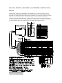
Overview
The CBLIO43-x1 , CBLIO52-x1 , CBLIO43DE-x1 , and CBLIO52DE-x1 are cables with a DB15 connector
that converts 5VDC SmartMotor I/O to 24VDC I/O. The user will specify on the part number for cable
with either four digital inputs and three digital outputs (CBLIO43-x) or five digital inputs and two outputs
(CBLIO52) with or without DE option. The DE option brings 24Vdc or 48Vdc to the SmartMotor’s
control for SmartMotor with the DE option. The DE option on the cable and on the motor will allow the
user to take away power to the motor but keep power to the controller alive. This cable connects directly
into the SmartMotor’s DB 15 I/O connector (CN2) on the SM23xxD and SM34xxD series.
1
5M for x for 5m (16.4 ft) length
10M for x for 10m (32.8 ft) length
Inputs A to D can be set to either all sourcing or sinking inputs. Port G input is independent from input A
to D. Outputs E, F, and G are wired independently so they can either be sourcing or sinking.
RATING:
Input
min. voltage
max. voltage
min. current
max. current
24 VDC
30 VDC
5 mA
8 mA
max. voltage
max. current
30 Vdc
100 mA
Output
Damage may occur if these maximum ratings are exceeded.
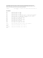
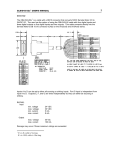
SmartMotor Interface
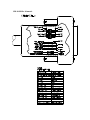
The CBLIO43-x, CBLIO52-x, CBLIO43DE-x, and CBLIO52DE-x cable use the following I/O pins on the
SmartMotor as listed:
PIN
1
SIGNAL
input A
2
input B
3
4
5
6
7
input C
input D
output E
output F
input/output G
12
13
14
15
+5Vdc
GND
GND
PWR
DESCRIPTION
Digital input A / Encoder input A / Step input (input frequency
50kHz)
Digital input B / Encoder input B / direction input ( input frequency
50kHz)
Digital input C / Positive Limit
Digital input D / Negative Limit
Digital output E
Digital output F
Digital input G ONLY for CBLIO52-x and CBLIO52DE-x
Digital output G ONLY for CBLIO43-x and CBLIO43DE-x
+5Vdc output
Signal Ground
for SmartMotor with DE option, Control GND
for SmartMotor with DE option, Control POWER
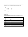
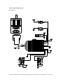
CBLIO43-x Schematic
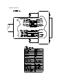
CBLIO52-x Schematic
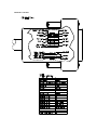
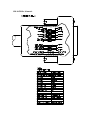
CBLIO43DE-x Schematic
CBLIO52DE-x Schematic
DE Control Power Input Rating
Input
min. voltage
max. voltage
min. current
max. current
24VDC
48VDC
60mA
100mA
Damage may occur if these maximum ratings are exceeded.
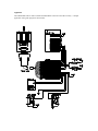
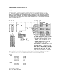
Application
The CBLIO52DE cable is used to interface the SmartMotor with a PLC and some coil relay. A sample
application wiring with program is shown below:
The above diagram is an example of using the CBLIO52DE-x cable to interface the SmartMotor with a
PLC. The sample program below reads output signal from the PLC to determine which predefined profile
to run. After a move completed, the SmartMotor will signal back to the PLC. Also, the SmartMotorTM will
send outputs to the SmartMotor if an error occurred.
'SAMPLE PROGRAM USING I/O
'INPUT A to C for PLC profile selection
'INPUT D for read ready
'OUTPUT G motor signal PLC after motion completed
'OUTPUT E and F to turn on/off pump and value
'
'initialize I/O ports
UAI
'initialize port A as input, signal input bit 0
UBI
'initialize port B as input, signal input bit 1
UCP
'initialize port C as RT Limit input
UDM
'initialize port D as LT Limit input
UE=1
'set output E off
UEO
'initialize port E as output, trajectory start(high)/ended(low)
UF=1
'set output F off
UFO
'initialize port F as output, fault(high)
UGI
'initialize port G as input, read ready trigger
'set Acceleration/velocity
MP
'set motor to ModePosition
A=8*100
'set acceleration to 100 rps^2 for motors with 500 line encoder
V=32212*30
'set velocity to 30 rps for motors with 500 line encoder
'read/check input loop
WHILE 1
WHILE UGI==1 LOOP
UF=1
ab[0]=UAI
LOOP
END
'infinite WHILE LOOP
'gate, waiting for PLC read ready signal
'reset the fault output if any
'if input A triggered, UAI will read 0,
' otherwise ab[0] is 1
ab[1]=UBI*2
'if input B triggered, UBI will read 0,
' otherwise ab[1] is 2
a=ab[0]+ab[1]
'summing up the binary values
SWITCH a
'comparing each binary value with the
' SWITCH/CASE
' statement
CASE 0
'CASE 0 when B A triggered ( 0 0 )
PRINT("CASE 0 move to P=8000",#13)
P=8000
'set position value
GOSUB0
'GO to SUBroutine C0 to start motion and
' error handling
BREAK
'BREAK out of SWITCH statement
CASE 1
'CASE 1 when B _ triggered ( 0 1 )
PRINT("CASE 1 move to P=10000",#13)
P=10000
'set position value
GOSUB0
'GO to SUBroutine C0 to start motion and
' error handling
BREAK
CASE 2
'CASE 2 when _ A triggered ( 1 0 )
PRINT("CASE 2 move to P=-8000",#13)
P=-8000
'set position value
GOSUB0
'GO to SUBroutine C0 to start motion and
' error handling
BREAK
CASE 3
'CASE 3 when _ _ triggered ( 0 0 )
PRINT("CASE 3 move to P=-10000",#13)
P=-10000
'set position value
GOSUB0
'GO to SUBroutine C0 to start motion and
' error handling
BREAK
ENDS
'ENDS for closing SWITCH statement
'LOOP for closing WHILE statement
'END marks end of program
C0
UE=0
G
TWAIT
UE=1
to PLC
IF Be
'Label for subroutine C0
'output high, trajectory started
'start trajectory (motion)
'wait until trajectory ends (motion stopped)
'reset signal to RESET MOTION (low) signal
'checking excessive position error bit
PRINT("excessive position error occured",#13)
'print to terminal window
UF=0
'set fault signal (high)
ENDIF
IF Bp
PRINT("RT Limit reached",#13)
UF=0
'checking RT limit bit
'print to terminal window
'set fault signal (high)
PRINT("LT Limit reached",#13)
UF=0
'checking LT limit bit
'print to terminal window
'set fault signal (high)
ENDIF
IF Bm
ENDIF
IF Bh
ENDIF
RETURN
'checking over temperature bit
PRINT("Over Temperature Occured",#13)'print to terminal window
UF=0
'set fault signal (high)
'RETURN to main program
You probably noticed that the motor is reading the signal low when high signal is being sent to the
CBLIO4352DE cable. If you prefer the motor to read a high signal when high signal is being sent to the
cable, you can mask the input value by using the following command:
a=UAI==0
‘this sets a to 1 if UAI is trun, which in this case if UAI is 0
‘
(low)
I/O Commands :
UAI
UBI
UCI
UDI
UCP
UDM
UGI
UGO
UG=1
UG=1
UEO
UE=1
UE=0
UFO
UF=1
UF=0
‘initialize
‘initialize
‘initialize
‘initialize
‘initialize
‘initialize
‘initialize
‘initialize
‘set output
‘set output
‘initialize
‘set output
‘set output
‘initialize
‘set output
‘set output
port A as input
port B as input
port C as input
port D as input
port C as Right Limit (Port C is right limit by default)
port D as Left Limit (Port D is left limit by default)
port G as input (port G can only be used as either
port G as outputinput or output)
G off (output line open)
G on (output line close)
port E as output
E off (output line open)
E on (output line close)
port F as output
F off (output line open)
F on (output line close)
d=UCI
‘store the input state value of port C into variable d
IF UAI
ENDIF
‘using with IF statement, true => UAI is 1
IF UAI==0
ENDIF
‘using with IF statement, true => UAI is 0
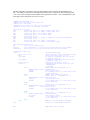
Another sample Wiring Diagram:
Using CBLIO52-x
For further details about I/O commands and program flows, please refer to the SmartMotorTM Users Guide.