1
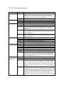
RTC 3000 Pinout Description
Group
Power
Motor
Hall Sensors
Pin
Supply
Gnd
PHA/PHB
PHC/+
+5V out
Gnd
HS3
HS2
HS1
Encoder
RS-485/RS-232
Communications
+5V out
Gnd
ENCA
ENCB
ENCI
+5V out
Gnd
RS-232TX
RS-232RX
RS-485A
RS-485B
Sync/UG
IOA & IOB/
Step & Direction/
Encoder 2 in
+5V out
Gnd
Input A
Input B
Description
Main input power: 0VDC min, 28VDC max. The RTC 3000 is
equipped with a 28VDC input shunting clamp to protect against
transients. Do not operate motor in a way, regenerative or otherwise,
that will cause the input voltage to rise above 28VDC.
Main input power return
2 phase motor - or 3 phase motor coil phase A: 3A peak, 1 A RMS
3 motor coil phase B: 3A peak, 1 A RMS
2 phase motor + or 3 phase motor coil phase C: 3A peak, 1 A RMS
Fused +5VDC output for hall sensor
+5V return
Hall sense 3 (120 o ). This must be appropriately connected if you are
using a 3 phase brushless motor. Ground this pin if you are using a
brush motor.
Hall sense 2 (120 o ). This must be appropriately connected if you are
using a 3 phase brushless motor. Leave this pin unconnected if you are
using a brush motor.
Hall sense 1 (120 o ). This must be appropriately connected if you are
using a 3 phase brushless motor. Leave this pin unconnected if you are
using a brush motor.
Fused +5VDC output for encoder
+5V return
Incremental quadrature encoder A, single ended
Incremental quadrature encoder B, single ended
Incremental quadrature encoder index, single ended
Fused +5VDC output
+5V return
RS-232 Transmit: hook this up to host receive
RS-232 Receive: hook this up to host transmit
RS-485 half duplex pin A: hook this up to host A
RS-485 half duplex pin B: hook this up to host B
User definable I/O. If used as a Sync pin to start motion, it is active
low. Otherwise, it is used as a TTL level digital input or output via the
UGI or UGO commands. It is equipped with an internal 1Kohm input
and the default state is Sync input.
Fused +5VDC output
+5V return
This pin has three functions: I/O A, Step input or external encoder A. If
used as an I/O, it is set up as an input or output via commands UAI or
UAO. It is equipped with an internal 1Kohm input. If the RTC 3000 is
used to control step and direction, it is the step input and is active high.
If an external encoder is being used, connect this pin to the quadrature
input A.
This pin has three functions: I/O B, direction input or external encoder
B. If used as an I/O, it is set up as an input or output via commands UBI
or UBO. It is equipped with an internal 1Kohm input. If the RTC 3000
is used to control step and direction, it is the direction input. Do not
change direction within 4 usec of the step input being high. If an
external encoder is being used, connect this pin to the quadrature input
B.
RTC 3000 Pinout Description (Continued)
Group
AniLink
Network
Pin
+5V out
Gnd
Data
Clock
+Limit
+5V out
Gnd
+Lim
+Limit
+5V out
Gnd
-Lim
Memory Port
External/Internal
+5V out
Gnd
Data Int.
Data Ext.
Clock.
Description
Fused +5VDC output
+5V return
Data line to AniLink peripherals – refer to peripheral for proper
connections
Clock line to AniLink peripherals – refer to peripheral for proper
connections
Fused +5VDC output
+5V return
Positive limit input. This input is active low and is equipped with an
internal 1Kohm pullup. If this input is activated, the motor will be
commanded to servo to a stop at the current acceleration (use F = 1) or
the amplifier will turn off (default state).
Fused +5VDC output
+5V return
Negative limit input. This input is active low and is equipped with an
internal 1Kohm pullup. If this input is activated, the motor will be
commanded to servo to a stop at the current acceleration (use F =1) or
the amplifier will turn off (default state).
Fused +5VDC output
+5V return
Enable for internal memory. To use the RTC 3000 internal memory,
connect this to Data Ext.
Connection for external memory. Connect this to the data line of the
external memory device. Refer to the data sheet for the external memory
module for more details.
Connection for external memory. Connect this to the clock line of the
external memory device. Refer to the data sheet for the external memory
module for more details.
Notes:
1. Refer to the Animatics SmartMotor User’s Manual for details on programming the RTC 3000.
2. All I/O, including A, B, G, hall, encoder, limit and memory ports are TTL interfaces. A valid low is
<0.8VDC and a valid high is >2.0VDC. For details on the internal pullups and protection clamps, refer
to the Animatics SmartMotor User’s Manual.
3. The total current that the RTC 3000 +5V outputs can source is 200 mA.