1
OPERATION AND USE OF THE ANIMATICS JOY2/3
JOYSTICK
1.
Introduction
1.1
Product Description
1.2
Features
1.3
Part Numbering
1.4
Theory of Operation
1.5
Simplified Schematic
2.
Specifications
2.1
Electrical
2.2
Mechanical
2.3
Environmental
3.
Installation
3.1
Unpacking and Inspection
3.2
Mounting
3.3
Wiring
3.3.1
Connector Pin Out
3.4
Power-up and Checkout
4.
Adjustments
4.1
AnilLink Bus Unit Address -- Jumpers 1, 2, 4
4.2
Contrast Trimmer Potentiometer
4.3
LED Back Light Jumper
5.
Maintenance and Repair
5.1
Maintenance
5.2
Indications
5.3
Trouble Shooting
6.
Programming
6.1
Series 5000 Command Set
6.2
SmartMotor Command Set
Animatics Corporation
3050 Tasman Drive
Santa Clara, CA 95054
Fax: 408-748-8725
Tel: 408-748-8721
FILE: H:\LIBRARY\PRODUCT\PERIPHER.ALS\JOYSTICK\USERMAN.UAL 2-5-1996
Page 1 /16
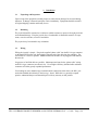
1.
1.1
Introduction
Product Description
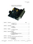
The JOY2/3 is a potentiometer-based, two axis joystick designed for use as part of an operator
interface for Animatics Motion controllers. The joystick relies on the AniLink network to
provide controller communications . The joystick has a toggle switch provides the option of
controlling either the X-Y or X-Z axes.
The JOY2/3 relies on a four-input, eight-bit analog input module, the AIO-100. The Series 5000
controller provides firmware level support for the joystick by addressing the AIO module several
times per second. Each return is scaled by a conversion velocity and used to set a velocity of a
Velocity Mode move.
The JOY2/3 is powered by the +5 V and ground lines on the AniLink. The AniLink Network is
a proprietary, serial-based, high-speed data network shared by the Series 5000 and
SmartMotor lines of motion control products.
1.2
Features
•
•
•
•
•
•
•
•
•
•
Simple plug in operation
2 / 3 axis control by selection switch
High speed / Low speed selection switch
Joystick On /Off (safety) switch
Convenient size and mounting
Firmware-level software support under both Series 5000
+5 V DC operation, powered by AniLink
AniLink Network Addressable
- High speed serial communications (100K bps)
- Multi-drop addressing,
Compatible with other AniLink peripheral modules
Four axis unit available
1.3
Part Numbering
The model number JOY2/3 identifies the standard 2 / 3 axis joystick module. Certain special
products of similar construction are manufactured within the same family of part numbers. Please
contact your application engineer for specific details about special products.
Animatics Corporation
3050 Tasman Drive
Santa Clara, CA 95054
Fax: 408-748-8725
Tel: 408-748-8721
FILE: H:\LIBRARY\PRODUCT\PERIPHER.ALS\JOYSTICK\USERMAN.UAL 2-5-1996
Page 2 /16
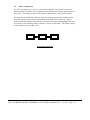
1.4
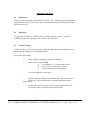
Theory of Operation
The JOY2/3 joystick acts as a slave to a Series 5000 controller. The joystick is based on an
eight-bit analog I/O module. The I/O module has two inputs in series with the precision pots of
the joystick. The voltage seen by the I/O changes as the resistance of the joystick changes.
The Series 5000 controller has a firmware level loop which queries the AIO module mounted
inside the joystick several times per second about the position of the joystick arm. When a
return from the AIO module is received by the controller, the values corresponding to each axis
are scaled by a user-controlled value to calculate a velocity for the motors. The units of velocity
are determined by the (axis)SPU value.
Host PC
Controller
Joy 2/3
System Block Diagram
Animatics Corporation
3050 Tasman Drive
Santa Clara, CA 95054
Fax: 408-748-8725
Tel: 408-748-8721
FILE: H:\LIBRARY\PRODUCT\PERIPHER.ALS\JOYSTICK\USERMAN.UAL 2-5-1996
Page 3 /16
2.
Specifications
Note -- All listed specifications are believed correct as of the date of printing. See errata for latest
details. Any and all product specifications are subject to change without notice by the
manufacturer.
2.1
Electrical
Bus DC line voltage
5V DC
Normal Maximum DC current
65 ma
2.2
Mechanical
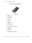
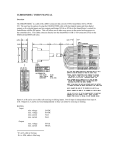
Dimensions:
See Figure
Case: 9” x 5-9/16” x 2-1/2”, allow 4” minimum clearance for joystick handle.
Weight: 48 oz
Animatics Corporation
3050 Tasman Drive
Santa Clara, CA 95054
Fax: 408-748-8725
Tel: 408-748-8721
FILE: H:\LIBRARY\PRODUCT\PERIPHER.ALS\JOYSTICK\USERMAN.UAL 2-5-1996
Page 4 /16
2.3
Environmental
Operating temperature
Storage temperature
Humidity
Animatics Corporation
0°C to 50°C
-20°C to 70°C
0 % to 90 % (non-condensing)
3050 Tasman Drive
Santa Clara, CA 95054
Fax: 408-748-8725
Tel: 408-748-8721
FILE: H:\LIBRARY\PRODUCT\PERIPHER.ALS\JOYSTICK\USERMAN.UAL 2-5-1996
Page 5 /16
3.
3.1
Installation
Unpacking and Inspection
Upon receipt of the equipment, carefully inspect to ensure that no damage has occurred during
shipment. If damage is detected, notify the carrier immediately. Equipment should be stored in
its original shipping container until ready for use.
3.2
Mounting
The joystick should be mounted on a cabinet or suitable enclosure to protect it from physical and
environmental damage. Keep the joystick free of combustible or flammable material, oil vapor,
steam, excessive moisture, corrosives and debris.
The joystick may be mounted in any orientation.
3.3
Wiring
Wiring the joystick is simple. Plug in the supplied “phone cable” into the RJ11-6 type connector
on the bottom PCB of the unit, then plug the opposite end of the cable into the controller. The
second RJ11-6 is wired in parallel. Additional AniLink modules can be plugged in and added to
the network.
Longer runs of AniLink cable are possible. Maximum tested runs for the “phone cable” wiring
and RJ11-6 type connectors are about 6 feet. Use of higher efficiency shielded cable and better
connectors will allow greatly expanded performance.
User looking for more industrial-type communications connections often remove the RJ11 jack
and solder shielded cable directly to the lower p.c. board. While this is a generally accepted
practice, understand that poor workmanship will void any warranty on this product.
Animatics Corporation
3050 Tasman Drive
Santa Clara, CA 95054
Fax: 408-748-8725
Tel: 408-748-8721
FILE: H:\LIBRARY\PRODUCT\PERIPHER.ALS\JOYSTICK\USERMAN.UAL 2-5-1996
Page 6 /16
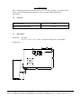
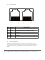
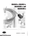
3.3.1 Connector Pin Out
1
6
1
6
Connector C1 (RJ11-6 connector, x 2 in parallel)
PIN
3.4
SIGNAL
DESCRIPTION
1
IN #5
Speed Select
2
+5 V DC
AniLink Power from controller (limited to about 150 Ma)
3
GND
To controller
4
CLOCK
Aniline Clock
5
DATA
Aniline Data
6
IN #6
Joy On/Off
Power-up and Checkout
No particular power up procedure is necessary for the JOY2/3 joystick. Be sure to apply
common safety practices when working on any motion based system: Before you power up your
system for the first time, make sure that there is no possibility of personal injury or machine
damage.
Animatics Corporation
3050 Tasman Drive
Santa Clara, CA 95054
Fax: 408-748-8725
Tel: 408-748-8721
FILE: H:\LIBRARY\PRODUCT\PERIPHER.ALS\JOYSTICK\USERMAN.UAL 2-5-1996
Page 7 /16
4.
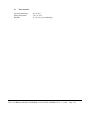
4.1
Adjustments
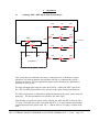
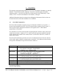
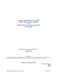
Adjusting +REF, -REF and the Input Potentiometers
15K
1K
15K
AIN0 X
15K
-REF
GND
1K
15K
AIN1 Y
+ 5 V DC
+REF
15K
1K
15K
AIN2 Z
AGND
VREF
15K
PCF8591P
1K
15K
AIN3 W
Your joystick has been calibrated at the factory. Under normal use, it should never require
adjustment. The following diagram and explanation will help you understand the joystick’s
operation and function. Call your applications engineer before attempting any adjustments or
calibration on your joystick.
The input and output signal ranges are tied to the PCF8591’s AGND and VREF signal levels.
The +REF and -REF potentiometers on the AIO-100 set the signal maximum and minimum.
The AIN# potentiometers are independent channel adjustments for the inputs, used to center the
input range. The input potentiometers are parallel to the AIN# wipers.
When building a proportional joystick, start by adjusting the +REF and -REF to allow the full 0 5V swing. Next adjust the joystick center point and the X, Y, Z, and W channel potentiometers
such that the neutral stick position reads 128 +/- 2 and the full 0 to 255 swing is available to the
stick.
Animatics Corporation
3050 Tasman Drive
Santa Clara, CA 95054
Fax: 408-748-8725
Tel: 408-748-8721
FILE: H:\LIBRARY\PRODUCT\PERIPHER.ALS\JOYSTICK\USERMAN.UAL 2-5-1996
Page 8 /16
4.2
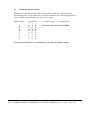
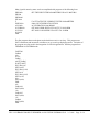
AniLink Bus Module Address
Peripherals on a AniLink network must have non-conflicting addresses to function properly.
This normally means a unique address for each AniLink peripherals. The AniLink peripherals use
a three bit address scheme based on the of jumpers 1, 2 and 4.
Module Address
A
B
C
D
E
F
G
H
Jumper State
1
2
3
O O O
X O O
O X O
X X O
O O X
X O X
O X X
X X X
X = jumper in place O = jumper absent
Bold values only valid on Series 50000
A joystick must use address A to be addressed by the JOY1ON firmware support.
Animatics Corporation
3050 Tasman Drive
Santa Clara, CA 95054
Fax: 408-748-8725
Tel: 408-748-8721
FILE: H:\LIBRARY\PRODUCT\PERIPHER.ALS\JOYSTICK\USERMAN.UAL 2-5-1996
Page 9 /16
Maintenance and Repair
5.1
Maintenance
There are no user serviceable components on the JOY2/3 units. The only periodic maintenance
requirement is to keep the clear of dust, dirt, or contaminant build up by cleaning with a damp
cloth when necessary.
5.2
Indications
The appearance of the power LED back light is a definite indicator of power. If power is
available and unit is not responding to the controller, check the cable.
5.3
Trouble Shooting
As these units have no user serviceable parts, trouble shooting is limited to checking for power
and ground, and checking for communications signal.
If your unit is not working:
0.
Check cabling for unplugged connectors or cable cuts
1.
Check for power using a DMM
A.
On connector C1: +5 between pins 2 and 3
B.
On IC 7805: +5 between pins 1 and 2
C.
External power source (if applicable)
If not receiving power, locate cause.
2.
Check for signal on AniLink Clock and Data lines using a logic probe or
oscilloscope. Logic and Data lines are normally high between data
transmissions.
3.
Animatics Corporation
If power, data and clock all show correct signals, and your unit is still
not working, return your unit for inspection and repair.
3050 Tasman Drive
Santa Clara, CA 95054
Fax: 408-748-8725
Tel: 408-748-8721
FILE: H:\LIBRARY\PRODUCT\PERIPHER.ALS\JOYSTICK\USERMAN.UAL 2-5-1996
Page 10 /16
6.
Programming
The languages and programming techniques for the Series 5000 and the SmartMotor are radically
different. Consistent between these languages is the direct command support and module
addressing scheme. Each AIO-100 card on an AniLink network can be addressed by a letter
address, A-D or A-H, and each module has four channels, 1 through 4.
Additional information about the command sets and languages demonstrated in this section can
be found in the Series 5000 and SmartMotor User’s Manuals.
6.1
Series 5000 Command Set
The Series 5000 command set supports two types of interaction with the Joy2/3 joystick. A
firmware based method based on the JOY1ON command allows complete joystick control. A
firmware based simple interrogation command is also supplied, JOY1?. Direct address
programming is also possible.
The AniLink bus on a Series 5000 controller runs throughout the controller, and is ported to the
outside in two locations. Addresses E, F, G, and H are used for processes within the controller
and are therefore not available to the outside network. See the Series 5000 User’s manual for
details on this feature.
The Series 5000 command set provides two levels of communication to the AIO-100: firmware
level joystick support, and direct communications commands. To be addressed by the firmware
level joystick commands, the target AIO-100 must use address A.
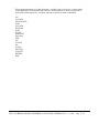
Command
AIN(let)
AOUT(let)#
JOYVH#
JOYVL#
JOY1OFF
JOY1ON
JOY1?
Comments
Upload the value of the corresponding analog input
(let) valid from A through D – module address
# valid from 1 to 4 – channel number
Set the level of the analog output for the corresponding module
(let) valid from A through D – module address
# valid from 0 though 255 – output level
Set the high speed max. deflection velocity for the JOY1ON mode,
#’s units determined by the system’s SPU values
Set the low speed max. deflection velocity for the JOY1ON mode
#’s units determined by the system’s SPU values
Disable the controller joystick mode
Enable the controller joystick mode
Returns the current channel levels of the AIO-100 module A in XYZW format
Joystick Programming
Animatics Corporation
3050 Tasman Drive
Santa Clara, CA 95054
Fax: 408-748-8725
Tel: 408-748-8721
FILE: H:\LIBRARY\PRODUCT\PERIPHER.ALS\JOYSTICK\USERMAN.UAL 2-5-1996
Page 11 /16
Many joystick control systems can be accomplished with programs of the following form:
XKP2000
XKI300
XKD5000
XIL3000
F
XSPU2000
ACC2000
JOYVH2000
JOYVL20
JOY1ON
END
‘SET THE PID FILTER PARAMETERS FOR ALL MOTORS
‘F ACTIVATES THE CURRENT FILTER PARAMETERS
‘2000 COUNTS PER REVOLUTION
‘ACCELERATION 2000 RPM/S
‘SET MAX HIGH SPEED VELOCITY TO 2000 RPM
‘SET MAX LOW SPEED VELOCITY TO 20 RPM
The first program that most designers and technicians want is a test loop. This program uses
GOTO statements and increments variables to set up a test loop displaying modes. Variations of
the program are often used in the integration of AIO-100 applications. Run the program from
TERM5000 in UNTERM mode.
VART500
VARA0
100
JOY1?
VARA?
AOUT[VARA]
WAIT[VART]
IF([VARA]=0)
GOTO(105)
IF([VARA]=128)
GOTO110
IF([VARA]=225)
GOTO(115)
200
GOTO(100)
END
105
VARA128
GOTO(200)
110
VARA225
GOTO(200)
115
VARA0
GOTO(200)
END
Animatics Corporation
3050 Tasman Drive
Santa Clara, CA 95054
Fax: 408-748-8725
Tel: 408-748-8721
FILE: H:\LIBRARY\PRODUCT\PERIPHER.ALS\JOYSTICK\USERMAN.UAL 2-5-1996
Page 12 /16
This program demonstrates a joystick subroutine. Auxiliary input #1 is used as a joystick enable
for this application. Note that JOY1ON mode uses Auxiliary inputs #5 and #6 as speed select
and joystick enable respectively. Auxiliary output #6 is used as an enable confirmation.
100
ACC40000
X200Y300F500
WAIT
ACC10000
X0Y0F200
WAIT
IF(1ON)
GOSUB105
GOTO100
END
105
JOY1ON
106
IF(1ON)
GOTO106
JOY1OFF
RETURN
END
Animatics Corporation
3050 Tasman Drive
Santa Clara, CA 95054
Fax: 408-748-8725
Tel: 408-748-8721
FILE: H:\LIBRARY\PRODUCT\PERIPHER.ALS\JOYSTICK\USERMAN.UAL 2-5-1996
Page 13 /16
Direct Command Programming
The 100 subroutine in the first joystick program relies on the JOY1? Command to format the
return from the AIO-100 module addressed as A. We could address other modules by slightly
changing the program.
…
AINB1?
AINB2?
AINB3
AINB4
VARA?
AOUTB[VARA]
…
Replaces from above
JOY1?
“
“
“
AOUTA[VARA]
The Series 5000 language can evaluate the complicated expressions used in some feedback
control algorithms.
VARA0
Initialization for first iteration
VARN0
Initialization for first iteration
100
Label statement
VARN[VARN+1]
VARB[AINA1/255]
VARB([VARB]+[AINA2/255])
VARB([VARB]+[AINA3/255])
VARB([VARB]+[AINA4/255])
VARB[VARB/4]
VARA(([VARA]*([VARN-1]))+[VARF]/[VARN])
AOUTA[VARAl*255]
Output the moving average
…
…
GOTO(100)
Animatics Corporation
3050 Tasman Drive
Santa Clara, CA 95054
Fax: 408-748-8725
Tel: 408-748-8721
FILE: H:\LIBRARY\PRODUCT\PERIPHER.ALS\JOYSTICK\USERMAN.UAL 2-5-1996
Page 14 /16
6.2 SmartMotor
Command Set
The SmartMotor has direct command software support for the AIO-100 module upon which the
JOY2/3 is based. There are two major differences in firmware support between the SmartMotor
and the Series 5000:
The SmartMotor uses a different self-diagnostic design than the Series 5000. This
different makes it possible to address up to eight unique AIO-100 modules on a single
SmartMotor AniLink network.
The SmartMotor does not have firmware level joystick support.
Since the SmartMotor is by its nature a single axis control system, the idea of using a multi-axis
joystick to control the motor seems unreasonable. The following is presented for testing and
demonstration purposes.
An example of a stored user program joystick program can be found in the SmartMotor User’s
Manual (JOY.SRC on page 234).
Command
AIN{port}input
AOUT{port}, exp.
RAIN{port}input
Comments
Port is valid from A through H
Input is valid from 1 to 4
Exp. expressions must evaluate to an integer
Fetch analog byte from port, input
Output an analog byte on channel port
Fetch analog byte from port: report ASCII integer value on RS-232
This program demonstrates the use of these commands.
MV
A=500
V=0
O0
UAI
UBO
RAINA1
RAINA2
RAINA3
RAINA4
WHILE 1
a=AINA1
V=a
b=AINA2
Animatics Corporation
‘Set mode velocity
‘Set acceleration to 500 = 63.13 rev. / sec.²
‘Set velocity = to 0
‘Set current position equal to the origin
‘Report channel 1 value
‘Report channel 2 value
‘Report channel 3 value
‘Report channel 4 value
3050 Tasman Drive
Santa Clara, CA 95054
Fax: 408-748-8725
Tel: 408-748-8721
FILE: H:\LIBRARY\PRODUCT\PERIPHER.ALS\JOYSTICK\USERMAN.UAL 2-5-1996
Page 15 /16
c=AINA3
d=AINA4
G
IF UA==1 GOSUB 0 ENDIF
LOOP
END
C0
UB=1
WHILE UAI==0 LOOP
UB=0
PRINT(“INPUT A1 = “,Ra,#13)
PRINT(“INPUT A2 = “,Rb,#13)
PRINT(“INPUT A3 = “,Rc,#13)
PRINT(“INPUT A4 = “,Rd,#13)
RETURN
END
Animatics Corporation
3050 Tasman Drive
‘Subroutine 0 reports on RS-232 in format
‘User output B signals you to get your finger off of A
‘Notice the formatting of this statement
Santa Clara, CA 95054
Fax: 408-748-8725
Tel: 408-748-8721
FILE: H:\LIBRARY\PRODUCT\PERIPHER.ALS\JOYSTICK\USERMAN.UAL 2-5-1996
Page 16 /16