1
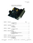
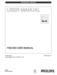
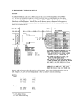
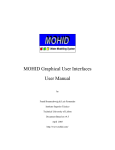
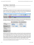
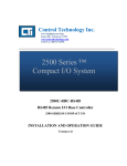
user’s guide
DIN - RS232
user’s manual
2
Overview
The DIN-RS232 is a DIN rail mount breakout
for SmartMotor™ RS-232 communications. It
allows a single master to communicate with up
to eight SmartMotors over RS-232 without the
loss of bandwidth typical of daisy chain propagation. Since this operation is nearly identical
to the operation of a RS-485 bus, the DINRS232 can also accommodate an RS-485
master. Hereafter, the SmartMotor™ version 3
and 4 products will simply be referred to as the
SmartMotor™. The DIN-RS232 provides an
interface between either an RS-232 or RS-485
host and up to eight SmartMotors via an optoisolated parallel bus. The connection to the
SmartMotors is not in daisy chain, eliminating
long propagation timing delays. The DINRS232 also provides a fused power distribution bus and the Animatics peripheral expansion bus.
The DIN-RS232 has three primary functions:
• Isolated parallel RS-232 interface
• Fused power distribution
• Animatics peripheral expansion bus
If one DIN-RS232 is used, the RS485 bias
switch has to be enabled for RS232 or RS485
communication. If more than one DIN-RS232
is used, only one of the DIN-RS232 needs to
have the RS485 bias switch enabled.
Absolute maximum ratings are levels beyond which damage may occur. The ratings for the DIN-RS232 are given below.
Absolute maximum fused power bus voltage:
48VDC
Absolute maximum fused power bus current:
20A RMS
Absolute maximum +5VC to any motor port:
+5.5VDC
Absolute minimum +5VC to any motor port:
-0.3VDC
Absolute maximum RS-232 input voltage:
-20VDC
Recommended +5VC motor port voltage:
5 -0.25 VDC
Typical +5VC motor port operating current:
35 mA DC
Animatics Corporation
Fax: (408) 748 8725 • Tel: (408) 748 8721 • www.animatics.com
DIN - RS232
user’s manual
3
Isolated Parallel RS-232 Interface
The DIN-RS232 provides an interface between either a RS-232 or RS-485 host and up to eight SmartMotors. More SmartMotors
can be hooked up by adding more DIN-RS232 units. The connection to the host is through one of two connectors, one for RS-232
and one for RS-485. While the RS-485 and RS-232 circuits share the same signal ground, they are optically isolated both from
the eight SmartMotor™ serial channels and power distribution circuitry.
The RS-232 interface uses a standard three wire hook up for a
nine pin D-subminiature connector. It is pinned for a standard 9
pin male-female RS-232 cable, not a null modem cable.
Unlisted pins have no connection.
The RS-485 interface is set to be a slave by default. This means
that the interface is always “listening” if nothing is being transmitted from a SmartMotor. In other words, the lines are floating
inputs. You may notice a pushbutton switch and LED next to the
RS-485 connector. If this button is pressed, the LED will either
light or go dark. If the LED is lit green, the RS-485 is biased with
with on-board pull-up, pull-down and terminating resistors as
shown in the schematic.
Due to the nature of RS-485, the biasing resistors, or their
equivalent, must exist somewhere in a RS-485 communication
bus. The terminator is required in particularly noisy environments or high baud rates. If these resistors are absent, intermittent or continuous communication errors may result. In
many cases, RS-485 transceivers that are designed as masters, or hosts, already incorporate this biasing, but not the terminating resistor.
Due to the nature of RS485, the biasing resistors, or their equivalent,
must exist somewhere in
a RS-485 communication bus.
The RS-485 interface is also a three pin hookup in a D-subminiature connector. As there is no generally accepted standard for RS-485 in a 9 pin D-sub, the pins were selected to
avoid accidental damage in the case the RS-232 plug is inserted into the RS-485 connector, or vice-versa.
Animatics Corporation
Fax: (408) 748 8725 • Tel: (408) 748 8721 • www.animatics.com
DIN - RS232
user’s manual
4
The RS-232 and RS-485 host interfaces are connected in parallel with each
other and all of the SmartMotors. A block diagram of this communications
function of the unit is given below:
There are two very important things to note and keep in mind when using the DIN-RS232. The
first is that all of the SmartMotors are effectively connected in parallel. In the typical RS-232 system, each node is connected in a series daisy chain, where each node passes information
sequentially down the chain. Each node takes a finite amount of time to receive and re-transmit
the message it receives, resulting in a total system propagation delay that grows with each node
that you add to the chain. If the nodes are in parallel, as in the case of the DIN-RS232, the time
delay is minimized and is independent of the number of SmartMotors used. Nothing is for free,
however, as this means that you have to ensure that no SmartMotor™ is talking at the same
time as another.
All of the SmartMotors
are effectively connected
in parallel
The second thing to note is that, while both the host RS-232 and RS-485 channels can fully
communicate with the SmartMotors, neither channel can communicate with or monitor the
other. Both host channels, however, always “see” what the SmartMotors are transmitting.
The SmartMotors connect to the DIN-RS232 via standard pitch terminal blocks. These are optically isolated from both the host serial channels and power distribution circuitry. Each set of terminal blocks is connected as follows.
Animatics Corporation
Fax: (408) 748 8725 • Tel: (408) 748 8721 • www.animatics.com
DIN - RS232
user’s manual
You must connect all four of these signals to the SmartMotor™ in order for the communications
to operate properly. Each SmartMotor™ interface is equipped with a disable switch. If the LED
just above this switch is red, the SmartMotor™ is powering the interface circuit, but communication both into and out of the SmartMotor™ is disabled. If the LED is green, communications
is enabled. If the LED is dark, the interface is not getting power.
Fused Power Distribution
The DIN-RS232 is equipped with a fused power
distribution circuit. The DIN-RS232 ships with
eight 250VAC, 8 ampere slow-blow fuses
installed. These are sufficient to handle many
applications, but careful analysis should be
made to verify that they are adequate for your
application. The fused power distribution circuit
is rated for 20 RMS amperes total. A schematic
of the fused power distribution is given on the
right .
Animatics Corporation
5
Each SmartMotor™
interface is equipped
with a disable switch. If
the LED just above this
switch is red, the
SmartMotor™ is powering the interface circuit,
but communication both
into and out of the
SmartMotor™ is disabled. If the LED is
green, communications
is enabled. If the LED is
dark, the interface is not
getting power.
The fused power distribution circuit is rated for
20 RMS amperes total.
Fax: (408) 748 8725 • Tel: (408) 748 8721 • www.animatics.com
DIN - RS232
user’s manual
6
Animatics Peripheral Expansion Bus
The expansion bus does not directly connect to any circuitry on the DIN-RS232. The Animatics Expansion Bus provides a convenient way to connect several SmartMotors and their DIN-rail mount expansion modules without using any additional cable. Every
Animators DIN-rail mount expansion module has two expansion bus connectors for receiving signals from modules on either end
of it. The bus passes through the module without any direct connection to any SmartMotor™ I/O or expansion module function. To
make use of the bus, it has to be connected to some SmartMotor™ I/O or expansion bus card through the jumpers.
Its primary purpose is to pass signals from other modules through, if necessary.
Animatics Corporation
Fax: (408) 748 8725 • Tel: (408) 748 8721 • www.animatics.com
DIN - RS232
user’s manual
7
Application
The diagram below shows a typical connection between a PLC to three SmartMotors.
The commands you would use to communicate with the SmartMotor™ are the same ones you
would normally use. From the SMI terminal screen, the command
2RP
still causes SmartMotor™ #2 to report its position back to the host.
Care is needed to ensure that none of the SmartMotors transmit at the same time. You would
not, for example, ever issue “0RP” from the SMI terminal, as this would tell all the SmartMotors
to report their positions at the same time. The result would be a tangle of bus collisions and unintelligible data.
Care is needed to
ensure that none of the
SmartMotors transmit at
the same time.
If you are using the RS-485 port, the SMI terminal needs to be set up appropriately. To do this,
click on Setup on the menu bar, followed by Configure Host Port. A dialog box entitled “Set Host
Communications Port” will pop-up. Near the upper right corner of the dialog box, click on the
radio button labeled “RS-485.” Close the dialog box by clicking the “OK” button. This procedure
sets up SMI to not expect any character echoes in all functions, such as terminal communications and user program download.
Animatics Corporation
Fax: (408) 748 8725 • Tel: (408) 748 8721 • www.animatics.com
DIN - RS232
user’s manual
8
It is important to note that the parallel nature of the DIN-RS232 requires that the SmartMotors
be addressed individually. This is easily done with the enable/disable switches at each of the
SmartMotor™ interfaces by the following procedure:
•
Disable all of the SmartMotor™ channels – all of the LEDs should be red or dark.
•
Enable the channel of the SmartMotor™ you wish to address. The LED on that channel
should be green.
•
Set the address – this is typically done with the ADDR# or ADDR= commands, downloading a program that contains the address, or writing to the data EEPROM that is read by the
user program.
•
Repeat the above until all addresses are set.
Storing the address in the data EEPROM is possible only in SmartMotor™ versions 4.15, 4.41,
4.75 and later. An example of a user code fragment that does this is given below:
EPTR=12
VLD(aaa,1)
ADDR=aaa
‘Set the data EEPROM pointer to 12
‘There is nothing special about the number 12
‘It is just a location in the data EEPROM
‘Load a single 32 bit value from the EEPROM
‘into the variable aaa.
‘Assign the value of aaa to be the
SmartMotor’s address.
This program needs to be in each SmartMotor™ user program. After loading the program into
each, you would have to put the correct address value into the data EEPROM at location 12 of
each SmartMotor. You would do this by the following command sequence:
EPTR=12
aaa=1
VST(aaa,1)
Note that the command “aaa=1” sets the address of the motor to be 1. If you wanted it to be 5,
you would have typed “aaa=5” instead.
For further details about the serial communications command and protocol statements, please
refer to the SmartMotor™ Users Guide.
Animatics Corporation
Fax: (408) 748 8725 • Tel: (408) 748 8721 • www.animatics.com