1
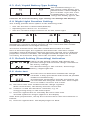
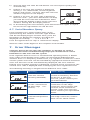
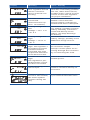
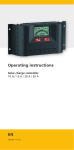
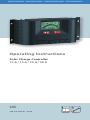
PHOTOVOLTAIK - PHOTOVOLTAIC - PHOTOVOLTAIQUE - FOTOVOLTAICA Operating instructions Solar Charge Controller 10 A / 15 A / 20 A / 30 A UK 708.219 (DE/UK) | 06.02 Contents 1. Safety instructions and liability disclaimer....................................3 1.1. The safety instructions are marked as follows.................................... 3 1.2. General Safety Instructions................................................................ 3 1.3. Scope of Application......................................................................... 4 1.4. Liability Disclaimer............................................................................. 4 2. Installation.....................................................................................5 2.1. Installation Site . ............................................................................... 5 2.2. Connecting the Regulator . ............................................................... 5 2.3. Grounding......................................................................................... 6 3. Protective functions of the controller ..........................................6 4. Operating the system regulator....................................................7 4.1. Display and Operation Elements........................................................ 7 4.2. Display Window................................................................................. 7 4.2.1. SOC Window..................................................................................... 7 4.2.2. Voltage window................................................................................ 7 4.2.3. Module current.................................................................................. 8 4.2.4. Charging current............................................................................... 8 4.2.5. Load current...................................................................................... 8 4.2.6. Ah – Battery charging meter.............................................................. 8 4.2.7. Ah – Battery discharging meter......................................................... 8 4.2.8. Warning deep discharge protection................................................... 8 4.2.9. Load disconnection............................................................................ 8 5. Function Overview.........................................................................8 5.1. SOC Calculation................................................................................ 8 5.2. PWM Charge Control ........................................................................ 9 5.3. Deep Discharging Protection............................................................. 9 6. Regulator Settings.........................................................................9 6.1. Calling up and Modifying the Settings.............................................. 9 6.2. SOC Setting / Voltage Control............................................................ 9 6.3. Gel / Liquid Battery Type Setting ..................................................... 10 6.4. Night Light Function Setting............................................................ 10 6.5. Default Setting (Presetting) Activation............................................. 10 6.6. Auto-test......................................................................................... 10 6.7. Serial Number Query........................................................................ 11 7. Error Messages . .........................................................................11 8. Guarantee....................................................................................13 9. Technicel Data..............................................................................14 Subject to change without prior notice! 708.219 | 06.02 1. Safety instructions and liability disclaimer 1.1.The safety instructions are marked as follows In this manual, safety instructions for personal protection are marked with this symbol. The relevant operational safety notes of the system and regulator are marked in bold. 1.2.General Safety Instructions Observe the following while installing the regulator and handling the battery: Danger of explosion due to improper handling of batteries! Corrosive hazard by leaking battery acid! Keep children away from batteries and acid! Smoking, fire and naked lights are prohibited when handling batteries. Prevent sparking and wear eye protection gear during installation. Observe and follow the handling instructions in the user manual and on the battery. Solar modules generate power from light incidence. Even by low light incidence solar modules carry the full voltage. Therefore, work cautiously and avoid sparking during all work. Observe the corresponding safety precautions. During installation and electrical installation, the photovoltaic system’s DC circuit may carry twice its system voltage value (in the 12 V system up to 24 V, 24 V system up to 48 V). Use only well-isolated tools! Do not use any technical measuring equipment that you know is damaged or defective! When installing the power line ensure that no fire safety measures are damaged. The regulator may not be installed and operated in moist rooms (e.g. restrooms), or rooms, in which easily flammable gasoline mixtures may be present, such as by gas bottles, paint, lacquer, solvents etc. Do not store any of the mentioned mixtures in the room, in which the solar regulator is installed! If the regulator is operated in a manner not specified by the manufacturer, the regulator’s constructive protective measures can deteriorate. The factory signs and marking may not be modified, removed or made unrecognizable. All work must be performed in conformity with the national electrical specifications and related local regulations! When installing the regulator in foreign countries, information concerning regulations and protective measures must be obtained from the relevant institutions / authorities. Do not begin the installation until you are sure that you have technically understood the manual and perform the work only in the order provided in this manual! The manual must be available during all work performed on the system, third parties included. This manual is a component of the system regulator and must be included with the regulator when given to a third person. 708.219 | 06.02 1.3.Scope of Application This manual describes the function and installation of a regulator for photovoltaic (PV) systems for charging 12 V or 24 V lead batteries for recreational, residential, business, commercial areas and small businesses. The charge regulator is only suitable for regulating photovoltaic solar modules. Never connect another charging source to the charge regulator. This can destroy the regulator and / or source. Consult your specialized dealer or installer if other charging sources should be used and observe the ”5.1. SOC Calculation” item in this manual. The regulator is only suitable for the following chargeable 12 V or 24 V battery types: - Lead storage batteries with liquid electrolytes - Sealed lead storage batteries; AGM, GEL The respective battery type must be set on the regulator, see ”6.3. Battery Type Gel / Li”. Observe the manufacturer’s instructions before connecting the battery. Important! The regulator is not suited for nickel cadmium, nickel metal hydride, lithium ions or other rechargeable or non-rechargeable batteries. Such batteries may not be connected to the regulator. Observe the respective battery’s safety instructions. The corresponding manufacture’s installation manual must be observed when installing the remaining components, e.g. solar module, battery or consumer. The regulator is not for outdoor use. The regulator must be installed so that it is protected against exposure to the elements, such as rain and direct sunlight. Vents may not be covered. Do not expose the battery regulator to rain. The regulator may only be used for the particular solar applications provided. Also, observe that the permitted, model-specific, nominal currents and voltages are not exceeded. No liability shall be assumed for any non-compliant usage. Carefully handle the product. 1.4.Liability Disclaimer The manufacturer cannot monitor the compliance to this manual as well as the conditions and methods during the installation, operation, usage and maintenance of the system regulator. Improper installation can cause damages and endanger people. Therefore, we assume no responsibility and liability for losses, damages or costs that result due to incorrect installation, improper operation, usage and maintenance or in any manner associated therewith. Similarly, we assume no responsibility for patent right or other right infringements of third parties caused by usage of this system regulator. The manufacturer reserves the right, without prior notification, to make modifications concerning the product, technical data or installation and operating manual. Caution: Opening the regulator, manipulation and repair attempts as well as improper operation voids the guarantee. 708.219 | 06.02 2. Installation 2.1.Installation Site Only install the regulator near the battery on a suitable surface. This surface should be solid, stabile, even, dry and nonflammable. The battery cable should be as short as possible (1-2 m) and have a suitable cable diameter size to minimize loss, e.g. use 2.5 mm² at 10 A and 2 m length; 4 mm² at 20 A and 2m length; 6 mm² at 30 A and 2 m length. The regulator and battery should have same temperature ratio for the temperature compensation function of the charging voltage. When the battery is placed far away from the regulator, an external temperature sensor is available as an accessory unit. Do not assemble the charge controller outdoors. The regulator must be installed so that it is protected against humidity, dripping, splashing and rain water as well as direct and indirect warming e.g. sunlight. The regulator also generates heat during normal operation. The installation or assembly into another housing may not obstruct the rear vents necessary for cooling the device. To ensure the air circulation for cooling the regulator, an area of 15 cm on each side of the regulator must be kept free. The temperature at the installation site may never fall below or exceed the maximal permitted ambient temperature. 15 cm 15 cm 15 cm 15 cm The integrated LC display should be protected against UV rays (e.g. sunlight). Chronic exposure to UV rays can permanently discolor the LCD. 2.2.Connecting the Regulator Connect the individual components to the symbols provided. Observe the following connection sequence during commissioning: 1. Connect the battery to the charge regulator - plus and minus 2. Connect the photovoltaic module to the charge regulator - plus and minus 3. Connect the consumer to the charge regulator - plus and minus The reverse order applies when deinstalling! Please observe that the automatic adjustment to 12V / 24V systems does not function properly, if this sequence order is not followed. An improper sequence order can damage the battery! 708.219 | 06.02 2.3.Grounding Grounding the regulator is not technically required when installing a standalone solar system. Observe, however, the corresponding applicable national regulations.One ground is possible for all positive connections; however, only one connection is possible for a negative ground. 96 MADE IN GERMANY X X 187 44 44 96 MADE IN GERMANY Observe that there is no common connection, e.g. across a ground connection, the minus module connections, battery minus and load minus. Non-observance can damage the regulator! 187 3. Protective functions of the controller The regulator is equipped with various devices to protect its electronics, battery and load. If the regulator’s maximal permitted data are exceeded, the regulator can break down despite the protective functions. Never improperly connect more than one component to the regulator! Error messages (Point 7. Error messages) display any protective devices triggered. The protective function is automatically reset after remedying the error. • Protection against reverse polarity of solar modules The solar module’s power may not exceed the regulator’s nominal power! • Protection against reverse polarity of the connected consumer at the load output Protects the regulator, not the consumer. • Protection against reverse polarity of connected battery Charging and discharging the battery is prevented. • Short-circuiting at the module input • Short-circuiting at the load output • Protection against over charging Regulator disconnects the connection to the battery and turns off the consumer. • Open circuit-proof during operation without battery or consumer Load output is protected from high module open circuit voltage directly flowing to load side. • Reverse current protection at night Prevents reverse current in the solar module at night. An additional reverse current diode is not necessary! • Overvoltage and undervoltage protection Immediately turns off the load output during insufficient or excessive battery voltage. • Excess temperature protection If the temperature inside the regulator is too high, the regulator’s load output is turned off to reduce power loss. • Overload protection at load output If the permitted load current is exceeded, the load output is turned off. • Transient overvoltage protection A varistor at the module input protects against overvoltage >47 V. The component limits the diverted energy to 4.4 joules. • Deep discharging protection / low voltage disconnect Prevents excessive deep discharging or overloading the battery. • Meets the European CE standards 708.219 | 06.02 4. Operating the system regulator The display shows a variety of system data by symbols and digits. Both buttons control all settings and display windows. Display window for system information and messages 96 MADE IN GERMANY 4.1. Display and Operation Elements Button for switching display windows or calling up the settings 44 Manual load switch, or confirmation button in program mode 4.2. Display Window 187 Symbols for current direction Battery symbol Sun: Charging/day Moon: Night Symbol for load Tools for error messages Face symbol for system status SOC Bar display SOC %V kA h Units display 7-Segment display for text and numbers Change the display windows with the left button. After switching windows, the window selected remains. To return to the beginning, simply press the left button until the SOC window appears. The bar display shows the actual battery level (SOC = state of charge) of the battery in each window. If the regulator is set to voltage control, the SOC bar display does not appear and the battery voltage value replaces the SOC percentage value! Please observe that the accuracy of the regulator’s display is not comparable to that of a measuring device! 4.2.1. SOC Window Displays the charge level, day / night level and consumer on / off. Instead of the SOC value, the battery voltage is displayed during voltage control. 4.2.2. Voltage window Displays the battery voltage measured by the regulator. 708.219 | 06.02 4.2.3. Module current Displays the actual produced solar module‘s current output. 4.2.4. Charging current Displays the charging current flowing into battery from the solar module. 4.2.5. Load current Displays the current drawn by the load output. 4.2.6. Ah – Battery charging meter Displays the accumulative sum of recharged Ah since the initial installation or reset. Press both buttons for 3 seconds to reset the meter to 0. Ever when the battery is disconnected the value remains. When 99.9 KAh are reached, it will switch back to 0 Ah. 4.2.7. Ah – Battery discharging meter Displays the accumulative sum of Ah drawn by load since the initial installation or reset. Press both buttons for 3 seconds to reset the meter to 0. When 99.9 KAh are reached, it will switch back to 0 Ah. 4.2.8. Warning deep discharge protection As an early warning, the SOC bar or the voltage value flashes. The face still looks friendly! 4.2.9. Load disconnection If the deep discharging protection has been activated the SOC bar or the voltage value flashes. The face looks sad until the reconnection setpoint is reached. 5. Function Overview This charging regulator has basic functions for specifying the charging state (SOC), charging specification and deep discharge protection that are described in the following section. Additional functions that can be activated such as the settings, night light function, auto-test, presetting and serial number query are explained under the corresponding menu items in chapter 6. 5.1. SOC Calculation During operation, the regulator monitors various parameters (U; I) of the battery and from that calculates the battery’s charge level (SOC = state of charge). The charge level is the energy level still available in the battery. Modifications in the system, e.g. the battery’s aging process are automatically taken into consideration by the system’s continuous learning process. 708.219 | 06.02 Using this SOC information, you always have an accurate overview on the actual battery level. Using the SOC, the regulator also controls the selection of the charging procedure and the deep discharging protection in order to ideally maintain the battery. If one of the parameters cannot be recorded because for example, a consumer or charging source is directly connected to the battery, the SOC calculation is invalid. The regulator can then be set to the more simplified voltage-guided control, see chapter 6.2. The SOC calculation is restarted each time the regulator is reinstalled. 5.2.PWM Charge Control The regulator applies a constant voltage charging to the battery. The entire available electricity provided by the charging source is used for charging the battery until the final voltage is reached. A pulse width modulator (PWM) regulates the charging current by briefly closing the module input (shunt charge controller) in the charge control area. Depending on the actual battery level, various charging procedures, float charging, boost charging and equalization charging are automatically performed. In doing so, the settings for the battery and control type are factored in. The final charging voltage is temperature compensated. Every 30 days a test is automatically performed to determine if an equalization charging must be carried out. 5.3.Deep Discharging Protection The regulator protects the connected battery against an excessive discharging. If the battery falls below a specified charge level (during SOC control) or battery voltage (during the voltage-controlled function), the load output is disconnected and the discharge of the battery is prevented. The display shows the early warning and disconnection during deep discharging. The setpoints of the deep discharging protection are predefined and cannot be reset. 6. Regulator Settings The battery type, control type and night light function can be set in the regulator. Points for the auto-test and the serial number query are also located within the menu. The settings remain when the battery is disconnected. 6.1.Calling up and Modifying the Settings Press the left button for at least 3 seconds to open the first setting window (control type). Press the left button again to call up the various windows. Press the right button to modify settings. The display begins to flash. Now, with the left button select the settings options. The setting must be saved with the right button. The display then stops flashing. The normal window reappears after a 30 second waiting period or pressing the left button for 3 seconds. This applies to all windows. 6.2.SOC Setting / Voltage Control The SOC control is the factory setting. This way, the charging procedure and the deep discharging protection are controlled by the calculated SOC value for ideal battery usage. Only fixed voltage thresholds are used and the SOC bar display is faded out in all windows during voltage-guided control (UoL). 708.219 | 06.02 6.3.Gel / Liquid Battery Type Setting The standard setting is “Li”. The setting of the battery type influences the cutoff voltage of the controller. If you use a Gel or AGM battery, you have to change the battery type to GEL. Caution! An incorrect battery type setting can damage the battery! 6.4.Night Light Function Setting This setting provides three options in the following order: • OFF: The function is deactivated (default). • Operating time-choice of 1 to 8 hours. • ON: The consumer output remains on for the entire night. This function controls the load output only when it is dark (at night). During daylight the consumer output remains off. The connected solar module records information on the light intensity. The load is activated once the solar module detects that it is dark. Once it becomes light, the regulator deactivates the consumer output regardless which illumination duration has been selected. Due to different properties of various modules, the twilight threshold cannot be specified accurately. An activation delay cannot be set when twilight sets in. 6.5.Default Setting (Presetting) Activation Calling up the default settings (PRE) deletes the previous settings and resets the charge controller to the factory settings. The default setting is: SOC Control / Gel Storage Battery / Night Light OFF 6.6.Auto-test The auto-test can determine whether the charge controller is fully operational and localize all possible windows simultaneously. The following preparations must be met before you can start the text using the menu item. Non-compliance can lead to incorrect test results. A) Disconnect the solar module from the charge regulator (both connections). The battery must be connected. B) Connect a small functional DC consumer, e.g. an energy-saving lamp, to the load output. C) Press the right button to manually disconnect the load. The load symbol no longer appears in the display. After these preparations, call up the auto-test menu item and continue as follows: D) Press the right button. The display begins to flash. 10 708.219 | 06.02 E) Start the auto-test with the left button. The test expires quickly and automatically. F) If there is no error, this window is displayed shortly (1. sec.) Afterwards, all LCD segments fade in and out for 1 second. Then the auto-test window reappears in the display. G) If there is an error, an error code is displayed. Note the code – your Steca distributor can help you find the error with this information. After 30 seconds the display returns to the auto-test window. During this the display flashes. H) In the flashing auto-test window, press the left button again to repeat the test or the right button to end the test. 6.7.Serial Number Query Each regulator has a serial number that can be queried using this window. Press the right button and the SN display begins to flash. Now, press the left button to display the number. The digits are displayed successively: - - - 1 2 3 4 5 6 7 8 - - - . Press the right button to stop or continue the display. Note the order of the digits for the complete serial number. 7. Error Messages Caution! Please do not open the regulator or attempt to replace components when troubleshooting. Improper maintenance can be hazardous to the user and the system. If the regulator detects errors or unauthorized operating states, it flashes error codes on the display. Error codes can generally be differentiated, whether there is a temporary malfunction, e.g. regulator overload or a more serious system error that can be remedied by appropriate external measures. Since not all errors can be simultaneously displayed, the error with the highest error number (priority) is displayed. If several errors are present, the second error code is displayed after remedying the more significant error. The following meaning is assigned to the different error codes: Display 708.219 | 06.02 Meaning Cause / Remedy Communication error with the internal memory (EEPROM). Disconnect consumer, solar module and battery. Reinstall the device. If the error reoccurs, please contact your specialized dealer. Communication error on the external bus (6-pole edge connector). Check the 6-pole plug-in connection on the edge connector, power supply and function of the external extension. If the error reoccurs, please contact your specialized dealer. Short-circuit at the external temperature sensor. Check the contact of the 2pole edge connector, remove short-circuit. Check sensor. 11 Display Meaning Cause / Remedy Excessive temperature regulator turned off the consumer due to internal over heating. Let regulator cool. Check the cause for overheating (installation site, other heat sources). Possible reduce charge or load current. Ensure the regulator has proper ventilation. No solar module connected. Check module connection. Module connected with reverse polarity, perhaps the module feed wire is disrupted. (Detection lasts approx. 15 minutes) Battery voltage too low. Voltage <10.5 V or <21.0 V Battery voltage too high. Voltage >15.5V or >31 V. Check installation. Check battery voltage, possibly recharge battery manually. Consumer connected directly to the battery can deep-discharge the battery. Check installation. Check battery voltage, possibly check additional charge sources. Load current too high. The regulator’s permitted consumer current has been exceeded, the load output has therefore been disconnected. Reduce the load current using the consumer output. Module current too high. Reduce the load current or module power. Perhaps current spikes are occurring through the consumer. Try reconnecting the load. The regulator’s permitted input current has been exceeded. Short-circuiting at the Remove short-circuit, disload output. connect consumer and try to reconnect. 12 If there is a short circuit in the module, the moon symbol appears during the day. The module input is protected by an internal electronic fuse. 708.219 | 06.02 Display Meaning Cause / Remedy No battery connected or connection interrupted. Supply only by solar module. Connect battery to regulator and check battery fuse. Storage battery connected with reverse polarity. Disconnect battery and connect to regulator with correct polarity. 8. Guarantee The manufacturer assumes the following guarantee obligations towards the end user: The manufacturer will remove all manufacturing and material faults that appear in the regulator and affect the correct functioning of the device during the guarantee period. Normal wear does not constitute a fault. The warranty is void if, after the end user completes the purchase contract, the fault is attributable to the end user or a third party, is caused in particular by improper installation or commissioning, improper or negligent handling, excessive wear, mechanical damage, inappropriate resources, faulty construction work, inappropriate building grounds or improper operation or use. The warrantee is only valid if after discovery, the fault is immediately claimed to your specialized dealer. The claim is to be sent by the specialized dealer to the manufacturer. A copy of the purchase contract must be enclosed. An exact fault description is required for a rapid settlement. The warrantee expires 24 months after the end user has completed the purchase contract, unless the manufacturer has expressively agreed to an extension period in writing. The manufacturer‘s warrantee based on the purchase contract with the end user is not affected by these present guarantee obligations. The manufacturer is entitled to carry out the warranty by repairing the fault or delivering a replacement. This does not include exchange, shipping or reinstallation costs. If repairs or replacement delivery are / is not possible or not carried out within an appropriate time despite a reasonable grace period determined by the customer, the decrease in value caused by the fault will be replaced or provided that is in the user’s interests not sufficient, the contract will be changed. Further claims against the manufacturer based on this guarantee obligation, in particular customer claims for damages due to lost profit, compensation for use and direct damages are excluded, provided claims must not be made according to law. The Steca GmbH is an ISO 9001:2000 certified company. 708.219 | 06.02 13 9. Technicel Data The technical data is suject to alterations by the manufacture. Elektrical Data Operating voltage 12 V or 24 V; automatic recognition Voltage range 12 V 6.9 V – 17.2 V Voltage range 24 V 17.3 V – 43.0 V Permitted operating temperature range -10 °C to +50 °C Permitted storage temperature range -20 °C to +80 °C Power consumption mA 12 V: ca. 12.5; 24 V: ca. 15.8 PWM-Frequency 30 Hz Maximum input voltage 45 V Minimum battery voltage 6.9 V Currents PR 1010 PR 1515 PR 2020 PR 3030 Max. continuous module current at 25 °C 10 A 15 A 20 A 30 A Max. continuous load current at 25 °C 10 A 15 A 20 A 30 A Excess Temperature Protection Disconnect load >85 °C Reconnect loadt <75 °C Data for final charging voltage Depends on set battery type Gel – storage battery (GEL) Liquid elektrolyte (Li) Float charge 14.1 V / 28.2 V 13.9 V / 27.8 V Boost charge; for 2:00 h 14.4 V / 28.8 V 14.4 V / 28.8 V Equalization charging; for 2:00 h --- 14.7 V / 29.4V 30 day maintenance charge, if necessary 14.4 V (28.8 V) 14.7 V (28.8 V) (for 2:00 h) (for 2:00 h) Temperature compensation 4 mV per °K and cells (internal sensor present, optional external sensor possible) 14 708.219 | 06.02 Charge controller activation Activation threshold of the charge type SOC Control Voltage control Float charge SOC >=70 % >=12.7 V resp. Boost charge SOC 40 % - 69 % 11.7 V - 12.4 V; resp. Equalization charge SOC <40 % < 11.7 V resp. 23.4 V 30 day maintenance charge if within 30 days no equalization or boost charge was active. >= 25.4 V 23.4 V - 24.8 V Load disconnection SOC Control Voltage control Early warning load disconnection SOC <40 % < 11.7 V / 23.4 V Load disconnection SOC <30 % < 11.1 V / 22.2 V Load reconnection SOC >50 % > 12.6 V / 25.2 V Mechanical Data Protection type IP 22 Installation wall installation Weight 350 g Housing recycledable, plastic housing Dimensions L x B x H 187 x 44 x 96 mm Fastening hole clearance vertical 60 mm; horizontal 177 mm Terminals (fine / strand) 16 mm²/ 25 mm² 708.219 | 06.02 / AWG: 6 / 4 mm² 15