1
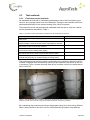
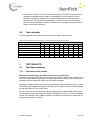
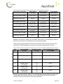
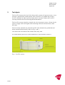
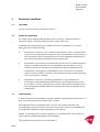
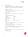
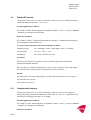
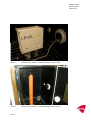
LevelTec Online monitoring of slurry storage tanks Test report Document information Document title Project Responsible Distribution Version Date Status LevelTec. Online Monitoring of Slurry Tanks. Test Report. ETV Test Center and Test Organisation Søren G. Rasmussen DANETV website 1-2 05-12-2012 Approved for publication TABLE OF CONTENTS TABLE OF CONTENTS ............................................................................................................... I 1 1.1 1.2 1.3 1.4 INTRODUCTION........................................................................................................... 2 Name and contact of proposer ...................................................................................... 2 Name of test body and test responsible ........................................................................ 2 Reference to test plan and specific verification protocol ................................................ 2 Deviations to test plan ................................................................................................... 2 2 2.1 2.2 2.3 2.3.1 2.3.2 2.4 TEST DESIGN .............................................................................................................. 2 Technology description ................................................................................................. 3 Test sites....................................................................................................................... 3 Test methods ................................................................................................................ 4 Performance test methods ............................................................................................ 4 Environmental test methods .......................................................................................... 5 Test schedule ................................................................................................................ 6 3 3.1 3.1.1 3.1.2 3.1.3 3.2 3.3 3.4 TEST RESULTS ........................................................................................................... 6 Test data summary ....................................................................................................... 6 Performance test results ............................................................................................... 6 Environmental test results ........................................................................................... 10 Additional test parameters ........................................................................................... 11 Test performance observation ..................................................................................... 13 Test quality assurance summary including audit results .............................................. 13 Amendments to and deviations from test plan ............................................................. 13 4 REFERENCES ........................................................................................................... 14 APPENDIX A ............................................................................................................................ 15 Terms and definitions................................................................................................................ 15 APPENDIX B ............................................................................................................................ 18 Test data report ........................................................................................................................ 18 APPENDIX C ............................................................................................................................ 20 DELTA Test Report: Environmental Testing of LevelTec Online Monitoring System ................. 20 i 1 INTRODUCTION This test report is prepared as part of the the verification of LevelTec online monitoring system for slurry storage tanks following the AgroTech Test Centre Quality Manual. 1.1 Name and contact of proposer LevelTec is developed and produced by PlusTec Aps, Mads Bjerresvej 8, DK-7500 Holstebro, Denmark. Website: www.plustec.dk. Contact person of PlusTec Aps: Jørgen Seerup. E-mail: [email protected]. Phone: +45 96 10 40 80. Mobil phone: +45 20 32 66 54. 1.2 Name of test body and test responsible The test activities were coordinated by DANETV, Test Centre AgroTech, Agro Food Park 15, DK-8200 Aarhus N, Denmark. Test responsible for the performance test was Søren G. Rasmussen, AgroTech. Phone +45 87 43 84 22. E-mail: [email protected]. Test responsible for the environmental test was Susanne Otto, DELTA. Phone: +45 72 19 41 13 . E-mail: [email protected]. 1.3 Reference to test plan and specific verification protocol This test report was made to meet the requirements defined in the verification protocol and test plan for LevelTec online monitoring system used for slurry storage tanks. 1.4 Deviations to test plan Due to many other ongoing tasks of the involved test staff it was not possible to follow the time schedule described in the test plan. Consequently, the test report was delayed. 2 TEST DESIGN The test was divided into two main parts: 1) Performance test undertaken by AgroTech test staff 2) Environmental test undertaken by test staff from DELTA LevelTec Test Report 2 AgroTech The main purpose of the performance test was to demonstrate that the alarm function of the online monitoring system is functioning as described by the technology supplier; i.e. that the alarm is triggered when it is supposed to be triggered. However, the test should also demonstrate, that number of “false alarms” is reduced to a minimum. This is partly because it is inconvenient and time consuming for the owner of the slurry storage tank to react on such false alarms. In addition, if the LevelTec system is sending a lot of false alarms there is a risk the slurry storage tank owner or the person responsible to react on alarms will not take action if he/she believes that there is no problem. The main purpose of the environmental test was to verify the ability of the LevelTec to withstand or operate within specified tolerances, while being exposed to the environmental conditions likely to be encountered during normal use. 2.1 Technology description LevelTec Online Monitoring System includes a pressure sensor, cabling and a control unit with a GSM modem for communication between LevelTec and mobile phones. The pressure sensor and cable are placed in a PVC tube mounted on a galvanised steel frame installed on the inner side of the storage tank wall. The pressure sensor is kept in a fixed position approximately 0.20 meter above the bottom of the slurry tank. Even small changes in the slurry level are measured by the pressure sensor. A decrease in the slurry level results in a lower pressure and vice versa. LevelTec is programmed so that when a sudden pressure decrease is measured a SMS-message is sent to the owner of the slurry tank or another person responsible for the slurry tank. The purpose of the SMS-message is to make it possible to take immediate actions in case of leakages. Thereby, it is possible to avoid or minimize pollution of nearby streams and lakes. The LevelTec Online Monitoring System is intended for storage tanks for all types of livestock slurry and for digested biomass from biogas plants. Normally, the total solids content of such matrices is within the range of 2.0 – 10.0 %. The overall purpose of LevelTec is to 1) detect a potential risk for leakage and 2) to report this electronically to the slurry storage tank owner or another person responsible for the tank. 2.2 Test sites The performance test was undertaken at Baanlev Biogas Plant, Bjergagervej 4, DK8380 Trige, Denmark. Contact person of test site is: Arne Jensen. Phone: +45 20 21 33 70. E-mail: [email protected]. By doing the performance test activities at a biogas plant it was possible to simulate leakages from a slurry tank under controlled conditions. The environmental test was undertaken in the laboratories of DELTA, Venlighedsvej 4, DK-2970 Hørsholm, Denmark. Contact person of test site is: Susanne Otto. Phone: +45 72 19 41 13. E-mail: [email protected]. LevelTec Test Report 3 AgroTech 2.3 Test methods 2.3.1 Performance test methods No standardized methods for undertaking performance test of online monitoring systems for slurry storage tanks have been identified. Therefore, test methods have been developed specifically for the present testing of the LevelTec system. The performance test was planned and undertaken with the aim to verify the 6 performance parameters described in Table 1. Table 1. Overview of the 6 performance parameters for the verification of LevelTec. Parameter Threshold value for reporting leakage measured as decrease in slurry level Time from threshold value in slurry level has been reached to SMS message is received by the person responsible for the tank Warning and alarm messages are received by the tank responsible person in case of slurry tank overflow An alarm is registered and communicated to person responsible for the tank in case of failing power supply Alarm is forwarded to a new person in case the communication to the first person did not result in actions that reset the alarm The LevelTec system is automatically switched on following a manual switching off (e.g. during emptying of storage tank) Value 0.05 meter 2 minutes Yes / no Yes / no Yes / no Yes / no The performance test was done using a small scale slurry container with the LevelTec installed. Leakages were simulated by opening a tap installed in the bottom of the slurry container. Figure 1 shows the small scale slurry container used for the performance test of LevelTec. Figure 1. The small scale slurry container used for the performance test of LevelTec. On the left photo the LevelTec control unit is seen as a grey box installed on the end of the slurry container. By undertaking the performance test at a biogas plant using slurry from many different farms it was possible to test the LevelTec Online Monitoring System using different LevelTec Test Report 4 AgroTech slurry types. The performance of LevelTec was tested and verified using five difference slurry types (matrices). An overview of the five slurry types is given in Table 2 below. Table 2. Overview of the five slurry types used for the performance test of LevelTec. No. 1 2 3 4 5 2.3.2 Description Total solids (%) Mixture of sow- and piglet slurry Mixed pig slurry with fodder residues Cow slurry Mixed pig slurry Fattening pig slurry 1.60 4.76 9.35 5.35 5.74 Environmental test methods Table 3 shows for each environmental test parameter the reference standard or reference specification used. Table 3. Overview of the 16 parameters included in the of environmental test of LevelTec and the corresponding reference standard or reference specification used. No. Parameter 1 2 3 4 5 6 7 8 Dry heat, operational Cold, operational including cold start-up Humidity Water, operational Transient shock, operational Impact (surface point), operational Cable bending Electrostatic discharge 9 Radiated RF immunity 10 Conducted radio frequency 11 Burst/Fast transients 12 Surge voltage 13 14 15 Radiated emission Conducted emission Power frequency H-field immunity 16 Voltage dips and interruptions Reference standard / specification IEC/EN 60068-2-2:2007 IEC/EN 60068-2-1:2007 IEC 60068-2-30 (2005) IEC 60529:2001 IEC/EN 60068-2-57:1999 IEC 60068-2-63:1991 Not available IEC 61000-4-2:2001 Performance criterion: B IEC 61000-4-3:2006 Performance criterion: A IEC 61000-4-6:2007 Performance criterion: A IEC 61000-4-4:2004 Performance criterion: B IEC 61000-4-5:2005 Performance criterion: B CISPR 16-2-3:2006 CISPR 16-2-1:2008 IEC 61000-4-8:2001 Performance criterion: A IEC 61000-4-11:2001 Performance criterion: B During the EMC immunity testing the following generic acceptance criteria for compliance were in force: Performance Criterion A: (For continuous phenomena): The EUT shall continue to operate as intended during and after the test. No degradation of performance or loss of function is allowed as defined in the relevant equipment standard and in the technical specification published by the manufacturer. LevelTec Test Report 5 AgroTech Performance Criterion B: (For transient phenomena): The EUT shall continue to operate as intended after the tests. No degradation of performance or loss of function is allowed as defined in the technical specification published by the manufacturer. During the test, degradation or loss of function or performance which is self-recoverable is, however, allowed but no change of actual operation state or store data is allowed. 2.4 Test schedule The test schedule for the performance test is presented in table 4 below. Table 4. Test schedule for the performance and environmental testing of LevelTec. Task 2012 Week no. Test plan preparation Practical planning Period for testing Test report drafting Test report quality assurance Test report final version 5-6 7-8 9-10 X X X X X 3 TEST RESULTS 3.1 Test data summary 3.1.1 Performance test results 11-12 13-14 X X X 15-16 17-18 X X 19-20 21-22 X X Detection and reporting a decrease in slurry level of 0.05 meter A number of test activities have been performed to verify the basic alarm function of the LevelTec Online Monitoring System: To detect a decrease in slurry level and when the threshold value is reached to report this via a SMS message. Leakages of different sizes are simulated by opening the tap to different extent. In tests to simulate large leakages the tap was full open and in tests to simulate small leakages the tap was open to a very small extent. As part of the test the time from the leakage started until the alarm-SMS was received on the mobile phone was measured. Also the decrease in slurry level from the leakage started until reception of the SMS-message was measured. Results from these test activities are presented in Table 5. LevelTec Test Report 6 AgroTech Table 5. Results from testing the basic alarm function in small scale slurry container. Slurry type 1: 1.60 % TS 1 Small leakage 7 mm/minut Medium leakage 43 mm/minut Large leakage 130 mm/minut 7 min, 30 sec. 2 min, 6 sec. 1 min, 0 sec. 50 mm 90 mm 130 mm Slurry type 2: 4.76 % TS Small leakage 6 mm/min. Medium leakage 33 mm/min. Large leakage 140 mm/min. Time to reception of SMS 8 min, 50 sec. 2 min, 18 sec. 1 min, 19 sec. 55 mm 75 mm 185 mm Slurry type 3: 9.35 % TS Small leakage 6 mm/min. Medium leakage 13 mm/min. Large leakage 54 mm/min. Time to reception of SMS 7 min, 40 sec. 4 min, 13 sec. 1 min, 45 sec. 45 mm 55 mm 95 mm Time to reception of SMS Decrease in slurry level Decrease in slurry level Decrease in slurry level 1 TS refers to total solids, a measure of the dry matter content of the slurry. Based on the results in Table 5 it is concluded, that LevelTec is functioning as claimed by PlusTec with respect to threshold value for reporting leakage. Table 6 presents the measured time from the threshold value in slurry level has been reached to an SMS-message is received by the person responsible for the tank. Table 6. Measured time from the threshold value in slurry level is reached to an SMS-message is received. Test no. 1 Type of leakage simulation One single leakage Decrease in slurry level (mm) 55 Time from leakage to reception of alarm-SMS 1 min, 30 sec. 2 One single leakage 50 1 min, 34 sec. 3 One single leakage 50 1 min, 52 sec. Leakage, part 1 Leakage, part 2 Total leakage Leakage, part 1 Leakage, part 2 Total leakage Leakage, part 1 Leakage, part 2 Total leakage 25 40 65 20 30 50 25 30 55 No alarm after 15 min. 38 sec. --No alarm 15 min. 44 sec. --No alarm after 15 min. 55 sec. --- 4 5 6 Based on the test results in Table 6 it is concluded that an alarm-SMS is received within 2 minutes after the threshold value of 50 mm decrease in slurry level has been reached. This is according to the claim by the proposer. LevelTec Test Report 7 AgroTech Full tank warning and tank overflow alarm functions Leakages from slurry storage tanks can result from tank overflow. This will occur if slurry is pumped from the animal housing system to a storage tank, which is already full. It is claimed by the technology producer that LevelTec can be used to prevent this situation. According to the user manual an SMS warning message is sent to the tank owner when the level reaches 0.10 meter from the rim of the storage tank. The tank owner has to reset LevelTec after reception of an SMS warning message. If the slurry level continues to raise LevelTec sends an SMS alarm message, when the slurry level reaches 0.02 meter from the rim of the storage tank. As part of this verification the full tank warning and the tank overflow alarm functions were tested. The tests were performed using the small scale slurry container. First, the height of the container was artificially set to 0.45 meter. This was done by sending SMS-commandos to LevelTec. Then slurry was led to the slurry container and SMSmessages were waited for. Table 7 shows the results from these tests. Table 7. Results from testing the full tank warning and tank overflow alarm functions Message from LevelTec Full tank warning Slurry level measured when SMS was received 0.380 meter Tank overflow alarm 0.450 meter Comments In the time from LevelTec registers that the 0.10 meter threshold value is reached to the SMS warning message is received on the mobile phone the slurry level continues to raise. That is the reason why there is only measured 0.07 meter from the slurry level to the (artificial) rim of the slurry tank. In the time from LevelTec registers that the 0.02 meter threshold value is reached to the SMS warning message is received on the mobile phone the slurry level continues to raise. That is the reason why the slurry level has reached the (artificial) rim of the slurry tank when the SMS alarm message was received. It is seen from Table 7, that both the full tank warning message and the tank overflow alarm message were received. Thus, these functions are working as claimed by the technology supplier. Alarm function in case of failing power supply LevelTec online monitoring system has to be in operation 24 hours per day throughout the year to give the desired security. Thus, a stable power supply is required. Still, it is an advantage if the slurry tank owner receives a message in case the power supply is failing. This can be secured by installing a battery that makes it possible for LevelTec to send an SMS alarm message. The technology supplier claims that LevelTec has this function. This is tested as part of this verification. In table 8 the results from this test are shown. LevelTec Test Report 8 AgroTech Table 8. Results from testing LevelTec in case of failing power supply. Time when power supply was disconnected 12.03.2012 07:38 15.03.2012 10:48 15.03.2012 13:42 Time for reception of SMS alarm 12.03.2012 07:39 15.03.2012 10.50 15.03.2012 13:43 It is concluded from the test, that the alarm function in case of failing power supply is working as claimed by the technology supplier. Alarm forwarding function If a potential leakage is registered from the slurry storage tank it is crucial that the SMS alarm message is actually received by a person, who can take immediate actions to stop the leakage and minimize the risk for pollution of nearby streams and lakes. There is a risk that the person, to whom the SMS alarm message is sent, will not see this immediately. Perhaps the person has put the mobile phone away or the mobile phone has run out of battery. According to the technology supplier LevelTec will send an SMS alarm message to another mobile phone number if LevelTec is not reset 5 minutes after the SMS alarm message is sent. And if there is still no reaction from the receiver of the second SMS message an SMS alarm message is send to a third mobile number. LevelTec can forward the SMS alarm message to up to five mobile numbers. If there is still no action taken LevelTec sends SMS messages to the first mobile number again. This function has been tested as part of the verification. A leakage has been simulated in the small scale slurry container. When the SMS alarm messages were received resetting the LevelTec was omitted. The time for reception of the SMS alarm messages were registered. The test was repeated twice and the results are presented in table 9. Table 9. Results from testing the SMS alarm forwarding function of LevelTec. Time from reception of the first SMS alarm message 5 minutes 25 minutes Event SMS alarm message received on mobile number 2. SMS alarm message received on mobile number 1 again. It is concluded, that the alarm forwarding function is working as described by the technology supplier. Automatic switching-on LevelTec after manual switching-off Sometimes slurry is pumped from the storage tank to a slurry trailer to be applied on the field or to be moved to another tank or transported to a biogas plant. This will cause the slurry level to decrease and an SMS alarm message will be generated even though there is no leakage. To avoid SMS alarm messages in such situations it is possible to switch off the LevelTec alarm function for a certain number of hours. This is done by sending an SMS message to LevelTec. In the SMS message it is specified for how many hours LevelTec should be switched off. According to the technology supplier LevelTec will automatically switch on again after the specified number of hours. This function is tested and the results are presented in Table 10. LevelTec Test Report 9 AgroTech Table 10. Results from testing the automatic switching on LevelTec after manual switching-off. Time 8:41 Event An SMS-command is sent to LevelTec to switch off the alarm function for 1 hour: GYLLEOFF01 Reception of SMS message confirming switching off for 1 hour: OK The tap is opened to decrease the slurry level in the slurry container. The tap is closed after 0.30 meter slurry is drained off the slurry container. OK – no SMS alarm message is sent even though 0.30 meter slurry is drained off the slurry container. LevelTec has been switched off. The tap is opened to decrease the slurry level further. The tap is closed after 0.30 meter slurry is drained off. OK – no SMS alarm message is sent even though 0.30 meter slurry is drained off the slurry container. LevelTec is still switched off. Reception of SMS message confirming that LevelTec is now switched on again. The tap is opened to decrease the slurry level in the slurry container. Reception of SMS alarm message. OK – the alarm function of LevelTec has been automatically switched on again after 1 hour. SMS alarm messages are now sent when a decrease in slurry level is registered. 8:41 8:42 8:46 Result 1 8:50 8:54 Result 2 9:42 9:57 9:58 Result 3 Based on the results in Table 10 it is concluded that the functions of manual switching off and automatic switching on are working as claimed by the technology supplier. In Table 11 the results of the performance test are summarised. Table 11. Summary of the performance test of LevelTec. Parameter Threshold value for reporting leakage measured as decrease in slurry level Time from threshold value in slurry level has been reached to SMS message is received by the person responsible for the tank Warning and alarm messages are received by the tank responsible person in case of slurry tank overflow An alarm is registered and communicated to person responsible for the tank in case of failing power supply Alarm is forwarded to a new person in case the communication to the first person did not result in actions that reset the alarm The LevelTec system is automatically switched on following a manual switching off (e.g. during emptying of storage tank) Verified value 0.05 meter Maximum 2 minutes* Yes – these functions work as claimed. Yes – this function works as claimed. Yes – this function works as claimed. Yes – this function works as claimed. *Note: Under assumption of satisfactory mobile phone connection coverage. 3.1.2 Environmental test results Table 12 shows for each environmental test parameter the results of the environmental test activities. LevelTec Test Report 10 AgroTech Table 12. Results from evaluation of environmental test parameters. No. 1 Parameter Dry heat, operational 2 Cold, operational including cold start-up Humidity 3 4 5 Water, operational Transient shock, operational 6 Impact (surface point), operational 7 Cable bending 8 Electrostatic discharge 9 Radiated RF immunity Conducted radio frequency Burst/Fast transients Surge voltage 10 11 12 13 14 15 16 Radiated emission Conducted emission Power frequency H-field immunity Voltage dips and interruptions Result No malfunction was observed during the exposure. Further, no damages or deteriorations were observed during the visual inspection at standard atmospheric conditions. No malfunction was observed during the exposure. Further, no damages or deteriorations were observed during the visual inspection at standard atmospheric conditions. No malfunction was observed during the exposure. Further, no damages or deteriorations were observed during the visual inspection at standard atmospheric conditions. Neither ingress of water nor malfunction was observed after the exposure. No malfunction was observed during the exposure. Further, no damages or deteriorations were observed during the visual inspection performed after the exposure. No malfunction was observed during the exposure. Further, no damages or deteriorations were observed during the visual inspection at standard atmospheric conditions, except for cracking of black plastic part. No malfunction was observed during the exposure. Further, no damages or deteriorations were observed during the visual inspection at standard atmospheric conditions. No malfunction was observed during the exposure and the function of the test objects was OK after the exposure. Performance criterion: B. No malfunction was observed during the exposure and the function of the test objects was OK after the exposure. No malfunction was observed during the exposure, and the function of the test objects was OK after the exposure. No malfunction was observed during the exposure and the function of the test objects was OK after the exposure. No malfunction was observed during the exposure and the function of the test objects was OK after the exposure. The radiated emissions were within the specified limits. The conducted emissions were within the specified limits. No malfunction was observed during the exposure and the function of the test objects as OK after exposure. No malfunction was observed during the exposure and the function of the test objects was OK after the exposure. Based on the environmental test activities it is concluded that the test object (LevelTec online monitoring system complete with pressure sensor and cabling) meets the relevant requirements of the reference standards / reference specifications. Full information about the environmental test is included in the DELTA Test Report “Environmental Testing of LevelTec Online Monitoring System” performed for Plus Tec ApS (see Appendix C). 3.1.3 Additional test parameters LevelTec Test Report 11 AgroTech User manual The LevelTec user manual is 18 pages and formulated in Danish. The manual is read and evaluated as part of this verification. According to the user manual switching off the LevelTec alarm function can be done using two commands: ALARMOFFXX and GYLLEOFFXX. XX refers to the number of hours the alarm function shall be switched off. However, during the test it was only the command GYLLEOFFXX that actually switched off the alarm function. It is recommended that the user manual is updated accordingly. Moreover, it is recommended that the user manual is updated so it includes instructions for calibration of LevelTec. In addition, In general, the user manual contains full information and it is clearly formulated. Testing the function of LevelTec when the pressure sensor is covered by sand Normally, slurry contains a certain amount of sand e.g. from the fodder or from the wheels of the machines moving in and out of the livestock housing systems. Especially large amounts of sand are found in slurry from cow housing systems, where sand is used as bedding material for the cows. During storage the sand will sediment in the slurry storage tank under the formation of a base layer in the bottom of the tank. Over time this sand layer will accumulate since it is difficult to pump this out even after mixing the storage tank. Thus, since the pressure sensor is installed only 0.20 meter from the bottom of the slurry tank there is a risk that the pressure sensor will be covered by sand and this could potentially give problems for the performance of the LevelTec. As part of this verification the function of LevelTec was tested in a situation where the pressure sensor was covered. Figure 2 shows the test set-up. 1 2 3 Figure 2. Photo 1 shows the LevelTec pressure sensor installed in the small scale slurry container used for the performance test. Photo 2 shows the LevelTec sensor covered by sand. Photo 3 show how the sand is placed around the LevelTec sensor after the slurry container was filled with slurry and emptied again. It is seen that the sand is still laying around the sensor. LevelTec Test Report 12 AgroTech It was concluded from the test activities that uncertainties in the pressure measurements can occur when the LevelTec sensor is fully covered by a thick layer of sand. Thus, in such situations there is a risk that LevelTec will not detect a sudden decrease in the slurry level and send a SMS alarm message. To avoid this situation it is recommended the slurry tank owner to check the thickness of the sand layer once a year immediately after the storage tanks has been emptied in connection with land application of slurry. If the bottom layer has become so thick that there is a risk the pressure sensor will be covered actions should be taken to remove the sand (e.g. using an excavator) before slurry is pumped to the tank. Alternatively, the pressure sensor can be raised so that it is now place 0.40 - 0.50 meter from the bottom of the tank. However, if the pressure sensor is raised LevelTec has to be calibrated again. 3.2 Test performance observation All relevant observations made during testing are described in section 3.1. 3.3 Test quality assurance summary including audit results The test followed the AgroTech Test Centre Quality Manual, which is ISO 9001 compliant, but not certified. The test report have been subject to internal review by the verification responsible from AgroTech Test Centre, Torkild S. Birkmose. In addition, Anders Bonde Kentved, DELTA, has reviewed the test results of the environmental test activities performed by DELTA. No system audit was done for this verification. External review of the test report was done by Jørgen Hviid, Knowledge Centre for Agriculture, Agro Food Park 15, DK-8200 Aarhus N. The stability of the test equipment was controlled continuously by supervision and recording of data. Procedures for ensuring that test facilities and equipment are calibrated and fit for the purposes are described in the Quality Manual for the Laboratories of AgroTech. Data management including filing and archiving procedures are described in the AgroTech Test Centre Quality Manual. 3.4 Amendments to and deviations from test plan Due to many other ongoing tasks of the involved test staff it was not possible to follow the time schedule described in the test plan. Consequently, the test report was delayed. LevelTec Test Report 13 AgroTech 4 REFERENCES [1] AgroTech (2009): AgroTech Test Centre Quality Manual. Not published. [2] Plus Tec (2011): Product Sheet for LevelTec. In Danish. 2 pp. [3] Plus Tec (2011): User Manual for LevelTec. In Danish. 18 pp. [4] dlg Tele (2011): Product sheet for DLG slurry tank monitoring system. In Danish. 1 p. LevelTec Test Report 14 AgroTech APPENDIX A Terms and definitions LevelTec Test Report 15 AgroTech Word DANETV Analytical laboratory Independent analytical laboratory used to analyse test samples Application The use of a product specified with respect to matrix, target, effect and limitations DANETV Danish center for verification of environmental technologies DANETV test center Preliminary name for the verification bodies in DANETV with a verification and a test sub-body Effect The way the target is affected (Environmental) product Ready to market or prototype stage product, process, system or service based upon an environmental technology Environmental technology The practical application of knowledge in the environmental area Evaluation Evaluation of test data for a technology product for performance and data quality Experts Independent persons qualified on a technology in verification Matrix The type of material that the product is intended for Method Generic document that provides rules, guidelines or characteristics for tests or analysis Performance claim The effects foreseen by the vendor on the target (s) in the matrix of intended use Performance parameters Parameters that can be documented quantitatively in tests and that provide the relevant information on the performance of an environmental technology product Procedure Detailed description of the use of a standard or a method within one body Producer The party producing the product Standard Generic document established by consensus and approved by a recognized standardization body that provides rules, guidelines or characteristics for tests or analysis Target The property that is affected by the product Test center, test sub-body Sub-body of the test center that plans and performs test LevelTec Test Report 16 AgroTech Word DANETV Test center, verification subbody Sub-body of the test center that plans and performs the verification Test/testing Determination of the performance of a product for parameters defined for the application Verification Evaluation of product performance parameters for a specified application under defined conditions and adequate quality assurance LevelTec Test Report 17 AgroTech APPENDIX B Test data report LevelTec Test Report 18 AgroTech All relevant data from the performance test is presented in section 3.1.1 and section 3.1.3. Data from the environmental test are presented in section 3.1.2 and in Appendix C. LevelTec Test Report 19 AgroTech APPENDIX C DELTA Test Report: Environmental Testing of LevelTec Online Monitoring System LevelTec Test Report 20 AgroTech DELTA Test Report TEST Reg. no. 19 Environmental Testing of LevelTec Online Monitoring System Performed for Plus Tec ApS DANAK-19/12336 Project no.: T202349 Page 1 of 45 including 4 annexes 15 August 2012 DELTA Venlighedsvej 4 2970 Hørsholm Denmark Tel. +45 72 19 40 00 Fax +45 72 19 40 01 www.delta.dk VAT No. 12275110 This report is issued under the rules of DANAK (Danish Accreditation) and ILAC (International Laboratory Accreditation Cooperation) including its MRA (Mutual Recognition Arrangement). Further information can be found at www.danak.dk and www.ilac.org. The report must not be reproduced, except in full, without the written approval of DELTA. Version m DANAK-19/12336 DELTA-T202349 Page 2 of 45 Title Environmental Testing of LevelTec Online Monitoring System Test objects 3 pcs. of LevelTec Online Monitoring Systems complete with level sensor and cabling, serial nos. 2011-1201-011, 2011-1201-025, and 2011-1201-023. Detailed information is given in Section 2. The test objects were received 23 February 2012. Report no. DANAK-19/12336 Project no. T202349 Test period 22 March - 14 June 2012 Client Plus Tec ApS Mads Bjerres Vej 8 7500 Holstebro Denmark Contact person Mr Jørgen Seerup E-mail: [email protected] Tel.: +45 96 10 40 80 Manufacturer Plus Tec ApS Specifications DANETV Doc. D-5: “Environmental test specification for LevelTec Slurry Surveillance System”. Danske Landbrugsmaskinfabrikanters “Pålidelig jordbrugselektronik”, Maj 1989 Nordtest ELEC 016G, 1990. Results No malfunctions were detected. However, please note the observation made after impact, Section 4.6. The criteria for compliance are listed in Section 3.2. Test personnel SUO/lko Anders B. Kentved Henrik Egeberg Nielsen Poul Nørgaard Olling Truelsen DANAK-19/12336 DELTA-T202349 Page 3 of 45 Date 15 August 2012 Responsible Susanne Otto, B.Sc.E.E., B.Com (Org.) DELTA SUO/lko DANAK-19/12336 DELTA-T202349 Page 4 of 45 Table of contents Page 1. 1.1 1.2 Summary of test Introduction Conclusion 5 5 5 2. 2.1 2.2 Test objects Test objects Auxiliary equipment 6 7 7 3. 3.1 3.2 3.3 3.4 General test conditions Test setup Criteria for compliance Functional test Standard environment 8 8 8 8 9 4. 4.1 4.2 4.3 4.4 4.5 4.6 4.7 4.8 4.9 4.10 4.11 4.12 4.13 4.14 4.15 4.16 Test and results Dry heat, operational Cold, operational including cold start-up Humidity Water, operational Transient shock, operational Impact (surface point), operational Cable bending Electrostatic discharge Radiated RF immunity Conducted radio frequency Burst/Fast transients Surge voltage Radiated emission Conducted emission Power frequency H-field immunity Voltage dips and interruptions 10 10 10 11 12 13 13 14 15 16 16 18 19 21 22 22 24 Annex 1 List of instruments 26 Annex 2 Photos 28 Annex 3 Measurement curves - Emission 38 Annex 4 Test setup and functional test procedure 43 SUO/lko DANAK-19/12336 DELTA-T202349 Page 5 of 45 1. Summary of test 1.1 Introduction The testing is performed according to DANETV Doc. D-5: “Environmental test specification of LevelTec Slurry Surveillance System”. The specification is based on the manufacturer’s product sheet, on-site inspection at a farm at Rostved, Danske Landbrugsmaskinfabrikanters “Pålidelig jordbrugselektronik”, Maj 1989, Nordtest ELEC 016G: 1990, and SPM-179: “Acceleration factors and accelerated life testing, 2011. The purpose of the environmental testing is to verify the ability of the test object to withstand or operate within specified tolerances, while being exposed to the environmental conditions likely to be encountered during normal use. The selection of the severity of each of the tests is based on the following conditions: The test aims to produce the same failure mechanisms as may be encountered during use. Only a few samples of the test objects are exposed to each test. Thus, variations in tolerances have to be taken into account. The verbal description of the use environment, see Section 2.1. The compliance of the LevelTec Online Monitoring System to electrical safety, as well as the compliance of the GSM module to the RTTE-directive, is not covered. 1.2 Conclusion The test object mentioned in this report meets the relevant requirements of the specification/standards stated below. DANETV Doc. D-5: “Environmental test specification for LevelTec Slurry Surveillance System”. However, please note the observation made after impact, Section 4.6. The test results relate only to the objects tested. SUO/lko DANAK-19/12336 DELTA-T202349 Page 6 of 45 2. Test objects The LevelTec measures the level of the slurry tank by means of a pressure sensor. A text message is transmitted to mobile phones at the occurrence of a sudden drop in slurry level or a full tank, in order to protect nearby lakes or streams. Further, the LevelTec currently transmits data for monitoring and documentation. The LevelTec system comprises a control unit, a level (pressure) sensor, a fixture for the sensor, a supply cable and a signal cable connecting electronic unit and sensor, and a PVC tube. The level sensor and cable are protected in a PVC tube mounted on a galvanised steel frame mounted inside the slurry tank, see Fig. 1 and 2. The control unit is mounted on the outside of the slurry tank. For further details, please refer to the manufacturer’s specifications in Annex 1. Fig. 1. LevelTec system. SUO/lko DANAK-19/12336 DELTA-T202349 Page 7 of 45 Fig. 2. Mounting of LevelTec pressure sensor. 2.1 Test objects Test objects 2.1.1 Model / type 3 pcs. of LevelTec Online Monitoring Systems complete with level sensor and cabling - Part no. Serial no. 2011-1201-011, 2011-1201-025, and 2011-1201-023. Manufacturer Supply voltage Plus Tec ApS 230 VAC Comments - Name of test object 2.2 Auxiliary equipment Auxiliary equipment 2.2.1 SUO/lko Name of auxiliary equipment Model / type Various mobile phones - Part no. - Serial no. Manufacturer - Supply voltage Comments For communication with LevelTec Online Monitoring system DANAK-19/12336 DELTA-T202349 Page 8 of 45 3. General test conditions 3.1 Test setup A photo of the test setup is enclosed in Annex 4. 3.2 Criteria for compliance No change of the actual operational states of the test object is allowed. However, temporary change is allowed during the power supply failure test. In addition, the following generic acceptance criteria for compliance were in force during the EMC immunity testing: 3.3 Performance Criterion A: (For continuous phenomena): The EUT shall continue to operate as intended during and after the test. No degradation of performance or loss of function is allowed as defined in the relevant equipment standard and in the technical specification published by the manufacturer. Performance Criterion B: (For transient phenomena): The EUT shall continue to operate as intended after the tests. No degradation of performance or loss of function is allowed as defined in the technical specification published by the manufacturer. During the test, degradation or loss of function or performance which is self-recoverable is, however, allowed but no change of actual operating state or stored data is allowed. Performance Criterion C: Temporary degradation or loss of function or performance is allowed during and after the test, provided the function is selfrecoverable, or can be restored by the operation of the controls as defined in the relevant equipment standard and in the technical specification published by the manufacturer. Functional test A functional check, demonstrating compliance with the requirements stated by Plus Tec ApS, is performed before the actual testing is started. The functional check is performed before, in some cases during, and after each environmental exposure in order to verify the ability of the test object to withstand the environmental conditions without impairment of the function. Further, a visual inspection with the un-aided eye is performed after each exposure in order to detect mechanical damages or deteriorations. The functional test procedure is given in Annex 4. SUO/lko DANAK-19/12336 DELTA-T202349 Page 9 of 45 3.4 Standard environment Normal environmental condition: SUO/lko Temperature : 15 °C - 35 °C Humidity : 25 % RH - 75 % RH Air pressure : 86 kPa - 106 kPa (860 mbar - 1060 mbar) Power supply voltage : Unom. ±3 % DANAK-19/12336 DELTA-T202349 Page 10 of 45 4. Test and results 4.1 Dry heat, operational The purpose of this test is to verify the ability of the test object to operate according to specifications at the upper temperature limit of the use environment. Product/application standard Danske Landbrugsmaskinfabrikanters “Pålidelig jordbrugselektronik”, Maj 1989 Nordtest ELEC 016G. Reference standard IEC/EN 60068-2-2:2007, Test Be: Dry heat for heat-dissipating specimen with gradual change of temperature. Severity (control unit) Temperature : +70 °C Duration : 16 hours Temperature : +40 °C Duration : 16 hours Severity (level sensor) Procedure The test object is switched ON during the exposure. A functional check is performed during the last part of the exposure at the high temperature. Further, a visual inspection is performed after returning to standard atmospheric conditions. Result No malfunction was observed during the exposure. Further, no damages or deteriorations were observed during the visual inspection at standard atmospheric conditions. 4.2 Cold, operational including cold start-up The purpose of this test is to verify the ability of the test object to initiate normal operation and operate according to specifications at the lower temperature limit of the use environment. Product/application standard Danske Landbrugsmaskinfabrikanters “Pålidelig jordbrugselektronik”, Maj 1989 Nordtest ELEC 016G. SUO/lko DANAK-19/12336 DELTA-T202349 Page 11 of 45 Reference standard IEC/EN 60068-2-1:2007, Test Ad: Cold for heat-dissipating specimen with gradual change of temperature. Severity (control unit) Temperature : -25 °C Duration : 16 hours Temperature : +5 °C Duration : 16 hours Severity (level sensor) Procedure The test object is switched OFF during the exposure, except for the last hour where the test object is switched ON and a functional check is performed. Further, a visual inspection is performed after returning to ambient temperature. Result No malfunction was observed during the exposure. Further, no damages or deteriorations were observed during the visual inspection at standard atmospheric conditions. 4.3 Humidity The purpose of this test is to verify the ability of the test object to operate under and withstand the deteriorative effects of high temperature/humidity and cold condition. Product/application standard Danske Landbrugsmaskinfabrikanters “Pålidelig jordbrugselektronik”, Maj 1989 Nordtest ELEC 016G. Reference standard - cyclic test (control unit and level sensor) IEC 60068-2-30 (2005), Test Db: Damp heat cyclic (12 + 12 hours’ cycle), Variant 1. Severity and procedure SUO/lko Lower temperature : 25 C Humidity range at lower temperature : 95 - 100 %RH Upper temperature : 55 C Humidity range at upper temperature : 90 - 96 %RH Number of cycles : 6 DANAK-19/12336 DELTA-T202349 Page 12 of 45 Procedure The test object is switched OFF during the exposure, except for the first hour of upper temperature in the second and the sixth cycle where the test object is switched ON and the functional check monitors the operation of the test object. After this, the test object is switched OFF again. After recovery for 1 hour at laboratory temperature, a functional check and a visual inspection are performed. Result No malfunction was observed during the exposure. Further, no damages or deteriorations were observed during the visual inspection at standard atmospheric conditions. 4.4 Water, operational The purpose of this test is to verify the ability of the test object to operate according to specifications when exposed to water in the use environment. Product/application standard Danske Landbrugsmaskinfabrikanters “Pålidelig jordbrugselektronik”, Maj 1989 Nordtest ELEC 016G. Reference standard IEC 60529:2001, Degrees of protection provided by enclosures (IP Code). Severity (control unit including sensor cable) Water : IP X4 (protected against splashing water) Severity (level sensor including sensor cable) Water : IP X7 (immersion) Procedure The test object is switched OFF during the exposure. A functional test and a visual inspection with special attention to any water inside the product are performed after the exposure. Result Neither ingress of water nor malfunction was observed after the exposure. SUO/lko DANAK-19/12336 DELTA-T202349 Page 13 of 45 4.5 Transient shock, operational The purpose of this test is to verify the ability of the test object to withstand shocks likely to occur during normal use. Reference specification IEC/EN 60068-2-57:1999, Test Ff: Time-history method. Severity (control unit) Peak acceleration : 10 - 20 g Frequency range/RRS level : 5 - 25 Hz: +12 dB/oct 25 - 250 Hz: 50 g Number of shocks : 3 per axis Number of axes : 3, mutually orthogonal Peak acceleration : 40 - 80 g Frequency range/RRS level : 10 - 100 Hz: +12 dB/oct 50 - 500 Hz: 200 g Number of shocks : 3 per axis Number of axes : 3, mutually orthogonal Severity (level sensor) Procedure The test object, mounted on a fixture representing normal use, is placed on the vibrator table. The test object is switched ON and the functional check monitors the operation of the test object during the exposure. A visual inspection is performed after the exposure. Result No malfunction was observed during the exposure. Further, no damages or deteriorations were observed during the visual inspection performed after the exposure. 4.6 Impact (surface point), operational The main purpose of this test is to verify the ability of the test object to operate during impacts likely to occur during normal use. Reference specification IEC 60068-2-63:1991, Test Eg: Impact, spring hammer. SUO/lko DANAK-19/12336 DELTA-T202349 Page 14 of 45 Severity Impact energy : 1J Number of impacts : 3 at each point Impact points : Relevant accessible surfaces Procedure The test object is placed on a rigid plane test surface. The test object is switched ON and the functional check monitors the operation of the test object during the exposure. A visual inspection is performed after the exposure. Result No malfunction was observed during the exposure. Further, no damages or deteriorations were observed during the visual inspection at standard atmospheric conditions, except for cracking of black plastic part. 4.7 Cable bending The main purpose of this test is to verify the mechanical integrity of cable connections during conditions of cable bending likely to occur during normal use. Product/application standard Danske Landbrugsmaskinfabrikanters “Pålidelig jordbrugselektronik”, Maj 1989 Nordtest ELEC 016G. Severity (cable level sensor end) Number of bendings : 2500 per plane Force : 5N Procedure The sensor is fixated. The bending angle is limited to the maximum achievable during normal use. A visual inspection is performed after the exposure. Result No malfunction was observed during the exposure. Further, no damages or deteriorations were observed during the visual inspection at standard atmospheric conditions. SUO/lko DANAK-19/12336 DELTA-T202349 Page 15 of 45 4.8 Electrostatic discharge The purpose of the test is to verify that electrostatic discharge occurring on the equipment, or in its vicinity, does not affect its performance or causes malfunction or permanent damage. It is also a test of proper grounding or shielding inside the test object. Product/application standard EN 61000-6-2:2005: Electromagnetic compatibility (EMC) - Part 6-1: Generic standards - Immunity for industrial environments. Reference standard IEC 61000-4-2:2001: Testing and measurement techniques - Electrostatic discharge immunity test. Severity (control unit and level sensor) Air discharge : 2, 4, and 8 kV Contact discharge : 2, 4 and 8 kV Energy storage capacitance : 150 pF Discharge resistance : 330 Polarity : + and - Number of discharges : 10 per polarity at each test point Procedure The discharges are applied only to such points and surfaces of the test object which are accessible to personnel during normal use. Contact discharges are applied to conductive surfaces and coupling planes. Air discharges are applied to insulating surfaces. The test object is switched ON during the exposure. The test object is observed during the exposure, and a functional check is performed after the exposure. Results No malfunction was observed during the exposure and the function of the test objects was OK after the exposure. Performance criterion: B. SUO/lko DANAK-19/12336 DELTA-T202349 Page 16 of 45 4.9 Radiated RF immunity The purpose of the test is to verify the immunity of the test object to fields generated by intentional transmitters (radio, TV, cell etc.). Product/application standard EN 61000-6-2:2005: Electromagnetic compatibility (EMC) - Part 6-1: Generic standards - Immunity for industrial environments. Reference standard IEC 61000-4-3:2006: Testing and measurement techniques - Radiated, radio-frequency, electromagnetic field immunity test. Severity (control unit and level sensor including all cables) Frequency range : 80 - 1000 MHz / 1000 - 20000 MHz / 2000 - 2700 MHz Field strength : 10 V/m / 3 V/m / 1 V/m Modulation : 80 % AM, 1000 Hz sine wave Procedure The test is performed in an anechoic room. The field is generated using linearly polarised broadband antennas. The test object is switched ON during the exposure. The test object is observed during the exposure and a functional check is performed after the exposure. Results No malfunction was observed during the exposure and the function of the test objects was OK after the exposure. Performance criterion: A. 4.10 Conducted radio frequency The purpose of the test is to verify the immunity of the test object to low frequency fields generated by intentional transmitters (AM radio, TV, cell, etc.). Applicable to AC input and I/O cabling greater than 3 m in length. Product/application standard EN 61000-6-2:2005: Electromagnetic compatibility (EMC) - Part 6-1: Generic standards - Immunity for industrial environments. Reference standard SUO/lko DANAK-19/12336 DELTA-T202349 Page 17 of 45 IEC 61000-4-6:2007: Testing and measurement techniques - Immunity to conducted disturbances, induced by radio-frequency fields. SUO/lko DANAK-19/12336 DELTA-T202349 Page 18 of 45 Severity (control unit and level sensor including all cables greater than 3 m) Frequency range : 150 kHz - 80 MHz Amplitude : 10 Vrms Modulation : 80 %AM, 1000 Hz sine wave Procedure The test object is supplied with power via a coupling/decoupling network. The test signal is coupled to the power lines and signal lines via coupling networks or via an EM clamp. The coupling impedance is 150 . The test object is switched ON during the exposure. The test object is observed during the exposure, and a functional check is performed after the exposure. Results No malfunction was observed during the exposure, and the function of the test objects was OK after the exposure. Performance criterion: A. 4.11 Burst/Fast transients The purpose of the test is to verify the immunity of the test object to switching and transient noise. Applicable to AC/DC input and I/O cabling greater than 3 m. Product/application standard EN 61000-6-2:2005: Electromagnetic compatibility (EMC) - Part 6-1: Generic standards - Immunity for industrial environments. Reference standard IEC 61000-4-4:2004: Testing and measurement techniques - Section 4: Electrical fast transient / burst immunity test. Severity ((control unit and level sensor including all cables greater than 3 m) SUO/lko Amplitude : : 2 kV on power lines 1 kV on signal lines and earth lines Pulse rise time : 5 ns Pulse duration : 50 ns Generator impedance : 50 Repetition rate : 5 kHz DANAK-19/12336 DELTA-T202349 Page 19 of 45 Burst duration : 15 ms Burst period time : 300 ms Procedure Power port The test object is supplied with power via a transient coupling network. The test signal is successively coupled to each power line and protective earth with reference to the ground plane. The test signal is injected on the power lines for 5 minutes, using each coupling mode and each polarity, and then on the signal lines for 5 minutes using each polarity. Signal lines The test signal is injected on the signal lines using a capacitive coupling clamp. The clamp is successively used on selected signal cables. The test object is switched ON during the exposure. The test object is observed during the exposure and a functional check is performed after the exposure. Results No malfunction was observed during the exposure and the function of the test objects was OK after the exposure. Performance criterion: B. 4.12 Surge voltage The purpose of the test is to verify the immunity of the test object to switching and lightning-induced transients. Applicable to AC/DC power inputs, as well as I/O cabling which exceeds 30 m. Product/application standard EN 61000-6-1:2005: Electromagnetic compatibility (EMC) - Part 6-1: Generic standards - Immunity for industrial environments. Reference standard IEC 61000-4-5:2005: Testing and measurement techniques - Surge immunity test. Severity ((control unit and level sensor including all cables longer than 3 m) SUO/lko Amplitude power ports : 2 kV line-to-earth, 1kV line-to-line Amplitude signal ports : 1 kV line-to-earth DANAK-19/12336 DELTA-T202349 Page 20 of 45 SUO/lko Voltage rise time : 1.2 µs (open circuit) Voltage decay time : 50 µs (open circuit) DANAK-19/12336 DELTA-T202349 Page 21 of 45 Procedure The impedance of the test generator is 2 for line-to-line coupling and 12 for line-toearth coupling. The test object is switched ON during the exposure. The test object is observed during the exposure, and a functional check is performed after the exposure. Results No malfunction was observed during the exposure and the function of the test objects was OK after the exposure. Performance criterion: B. 4.13 Radiated emission The purpose of the test is to verify that the unintentional E-field emissions from the test object in normal operating mode is below the specified limits. Product/application standard EN 61000-6-3:2006: Electromagnetic compatibility (EMC) - Part 6-3: Generic standards - Emission standard for residential, commercial and light-industrial environments. Reference standard CISPR 16-2-3:2006: Specification for radio disturbance and immunity measuring apparatus and methods - Part 2-3: Methods of measurement of disturbance and immunity - Radiated disturbance measurements. Severity (control unit and level sensor including all cables) Frequency range : 30 - 1000 MHz Limits (quasi-peak) : 30 - 230 MHz : 230 - 1000 MHz : 30 dBV/m 37 dBV/m Procedure The electromagnetic field is measured with antennas at a distance of 10 m. The test object is switched ON and in normal operational mode during the measurement. Results The radiated emissions were within the specified limits. Test record sheets of the radiated emission measurements are enclosed in Annex 3. SUO/lko DANAK-19/12336 DELTA-T202349 Page 22 of 45 4.14 Conducted emission The purpose of the test is to verify that the unintentional emissions conducted back on the AC power mains are below the specified limits. Product/application standard EN 61000-6-3:2006: Electromagnetic compatibility (EMC) - Part 6-3: Generic standards - Emission standard for residential, commercial and light-industrial environments. Reference standard CISPR16-2-1:2008: Specification for radio disturbance and immunity measuring apparatus and methods - Part 2-1: Methods of measurement of disturbances and immunity - Conducted disturbance measurements Severity (control unit and level sensor including all cables) Frequency range : 0.15 - 30 MHz Limits (quasi-peak) : 0.15 - 0.5 MHz 0.5 - 5 MHz 0.5 - 30 MHz : : : 66 - 56 dBV 56 dBV 60 dBV Procedure The radio frequency voltage is measured at the power supply terminals of the test object by a receiver through an artificial mains network. The test switched ON during the measurement. Results The conducted emissions were within the specified limits. Test record sheets of the conducted emission measurements are enclosed in Annex 3. 4.15 Power frequency H-field immunity The purpose of the test is to verify the immunity of the test object to low frequency magnetic fields. Product/application standard EN 61000-6-2:2005: Electromagnetic compatibility (EMC) - Part 6-1: Generic standards - Immunity for industrial environments. SUO/lko DANAK-19/12336 DELTA-T202349 Page 23 of 45 Reference standard IEC 61000-4-8:2001: Testing and measurement techniques - Power frequency magnetic field immunity test. SUO/lko DANAK-19/12336 DELTA-T202349 Page 24 of 45 Severity (control unit and level sensor) Magnetic field strength : 30 A/m Test frequency : 50 Hz Procedure The test is performed in three orthogonal orientations. The test object is energised and in normal operational mode during the exposure. The test object is observed during the exposure, and a functional check is performed after the exposure. Results No malfunction was observed during the exposure and the function of the test objects was OK after the exposure. Performance criterion: A. 4.16 Voltage dips and interruptions The purpose of the test is to verify the immunity of the test object to fluctuations on AC power input. Product/application standard EN 61000-6-2:2005: Electromagnetic compatibility (EMC) - Part 6-1: Generic standards - Immunity for industrial environments. Reference standard IEC 61000-4-11:2001: Testing and measurement techniques - Power frequency magnetic field immunity test. Severity (control unit and level sensor including all cables) Line @ 0 % of nominal for 1 cycle Line @ 40 % of nominal for 10 cycles (50 Hz) Line @ 70 % of nominal for 25 cycles (50 Hz) Line @ 0 % of nominal for 250 cycles Procedure SUO/lko DANAK-19/12336 DELTA-T202349 Page 25 of 45 The test object is energised and in normal operational mode during the exposure. The test object is observed during the exposure, and a functional check is performed after the exposure. Results No malfunction was observed during the exposure and the function of the test objects was OK after the exposure. Performance criterion: B (0 % of nominal for 1 cycle)/C (remainder of exposures). SUO/lko DANAK-19/12336 DELTA-T202349 Page 26 of 45 Annex 1 List of instruments SUO/lko DANAK-19/12336 DELTA-T202349 Page 27 of 45 List of instruments NO. DESCRIPTION MANUFACTURER TYPE NO. 29232 HELMHOLZ COIL, LARGE EC PK 29646 PWR. ATT. 6 dB, 75W, DC-2GHz. BIRD ELECTRONIC CORPORATION 8308-60-N 29691 0.01 - 20 GHz. SYNTH. SWEEPER HEWLETT-PACKARD 83620A 29694 1-12 GHz. HORN ANTENNA. LOGIMETRICS AN 8200 F 29806 BROADBAND POWER AMPLIFIER, 10 AMPLIFIER RESEARCH kHz-220 MHz, 75 W 75A220 29815 3-LINE CDN NETWORK, IEC 61000-4- MEB 6 M3 29846 RF GENERATOR, 9 kHz-2.4 GHz 2024 29859 HEWLETT-PACKARD AC SOURCE W. HARMONIC/FLICKER TEST OPTION 29891 GENERAL IMMUNITY SOFTWARE, KURVEPROG VERS. 06 VBN PRTST 29911 DIGITAL MULTIMETER W. HPIB HEWLETT-PACKARD 34401A 29913 ELECTRICAL FAST TRANSIENT (BURST) GENERATOR EM TEST EFT 500 29914 ELECTRONIC SURGE GENERATOR EM TEST VCS 500 29985 BILOG ANTENNA 26-2000 MHz SCHAFFNER/CHASE 6140A 49002 SINGLE CHANNEL POWER METER DISPLAY UNIT ROHDE & SCHWARZ NRVS 49159 HF GENERATOR MARCONI 2024 49390 RF COUPLER, 2-18 GHz, 30 dB MIDWEST MICROWAVE INTERNATIONAL LTD CPL-5028-30NNN-79 49403 RF POWER AMPLIFIER, 800-4200 MHz, 15 WATTS OPHIR RF 5161F 49514 BURST CABLE 1 m DELTA RG223/U 49531 COAX RF DIODE DETECTOR, NEG. OUTPUT, CS TEST HEWLETT-PACKARD 8471D 49562 ESD GENERATOR, AIR AND CONTACT DISCHARGE SHAFFNER NSG438 49617 HIGH POWER RF AMPLIFIER, 80-1000 TESEQ MHz, 500 W EVFGT-50 EL.DYN LONG STROKE SHAKER MARCONI 6842A CBA1G-500 LING DYNAMICS V875-440 1127205 / 95 ACCELEROMETER BRÜEL & KJÆR 4371 22585 ACC. PRE-AMP. BRÜEL & KJÆR 2626 43236 VIBR. CONTROLLER LDS DACTRON LAS 200 EVFGT-47 CLIMATIC CHAMBER DELTA VKF875-3 EVFGT-34 WATER TEST FACILITY DELTA EVFGT-34 SUO/lko DANAK-19/12336 DELTA-T202349 Page 28 of 45 Annex 2 Photos SUO/lko DANAK-19/12336 DELTA-T202349 Page 29 of 45 Photo 1. Climatic tests; dry heat, cold and humidity (control unit). Photo 2. Climatic tests; dry heat, cold and humidity (level sensor). SUO/lko DANAK-19/12336 DELTA-T202349 Page 30 of 45 Photo 3. IP X4. Photo 4. Transient shock (control unit). SUO/lko DANAK-19/12336 DELTA-T202349 Page 31 of 45 Photo 5. Transient shock (level sensor). Photo 6. Cable bending. SUO/lko DANAK-19/12336 DELTA-T202349 Page 32 of 45 Photo 7. Impact (control unit). Photo 8. Impact (level sensor after impact). SUO/lko DANAK-19/12336 DELTA-T202349 Page 33 of 45 Photo 9. ESD (control unit). Photo 10. ESD (level sensor). SUO/lko DANAK-19/12336 DELTA-T202349 Page 34 of 45 Photo 11. Radiated RF immunity. Photo 12. Conducted radio frequency (control unit). SUO/lko DANAK-19/12336 DELTA-T202349 Page 35 of 45 Photo 13. Burst/fast transients. Photo 14. Surge voltage. SUO/lko DANAK-19/12336 DELTA-T202349 Page 36 of 45 Photo 15. Radiated emission. Photo 16. Conducted emission. SUO/lko DANAK-19/12336 DELTA-T202349 Page 37 of 45 Photo 17. SUO/lko Power frequency H-field Immunity. DANAK-19/12336 DELTA-T202349 Page 38 of 45 Annex 3 Measurement curves - Emission SUO/lko DANAK-19/12336 DELTA-T202349 Page 39 of 45 SUO/lko DANAK-19/12336 DELTA-T202349 Page 40 of 45 SUO/lko DANAK-19/12336 DELTA-T202349 Page 41 of 45 SUO/lko DANAK-19/12336 DELTA-T202349 Page 42 of 45 SUO/lko DANAK-19/12336 DELTA-T202349 Page 43 of 45 Annex 4 Test setup and functional test procedure SUO/lko DANAK-19/12336 DELTA-T202349 Page 44 of 45 Funktionstest (der skal være 230 VAC på enheden først!): 1. Tjek at sensoren er under ca. 1 m = 1000 mm vand i røret (husk at tolerancen er +/- 50 mm = 5 cm, så der er lidt at give af). 2. Send en SMS med LEVEL til enhedens tlf. nummer. Den skal svare med et level på omkring 1000 mm. 3. Træk sensoren et godt stykke (20 cm. eller sådan noget) op ad vandet og hold den der 30-60 sek. 4. Tjek at du modtager en SMS med LAEKAGE ALARM. 5. Tjek at de to hvide ledninger bliver ”kortsluttet” (relæerne) med et multimeter. 6. Put sensoren ned i vandet igen (1 m vand). 7. Tjek at de hvide ledninger stadig er ”kortsluttede”. 8. Tryk på den store blå ”Reset” knap og tjek at de hvide ledninger ikke er kortsluttede mere. 9. Hæld lidt mere end 5 cm ekstra vand i røret (dvs. lidt over den ekstra streg jeg har tegnet). 10. Tjek at du modtager en SMS med TANK FULD. 11. Tjek at de to hvide ledninger bliver ”kortsluttet” (relæerne) med et multimeter. 12. Tøm det ekstra vand af igen (så der bliver 1 m vand i røret igen). 13. Tjek at de to hvide ledninger ikke er kortsluttede mere (enheden resetter selv). 14. Udfyld arket med resultater som vi snakkede om i dag. Ovenstående er jo et komplet funktionstjek. Som vi aftalte skal det køres før og efter alle testene og der hvor du synes det passer. Undervejs i alle de forskellige forstyrrelser, skal enheden bare ”stå klar” og måle. Hvis en forstyrrelse giver mere end +/- 50 mm støj vil der blive sendt en besked til dig og relæerne vil trække. Dette er jo selvfølgelig meget UØNSKET for brugeren og skal derfor tjekkes/noteres. Der bør nok sidde et multimeter fast på de to hvide ledninger som man kan holde øje med undervejs. SUO/lko DANAK-19/12336 DELTA-T202349 Page 45 of 45 Test set-up outside climatic test chamber with control unit inside climatic test chamber Test set-up outside climatic test chamber with level sensor inside climatic test chamber SUO/lko