1
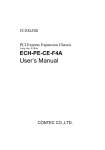
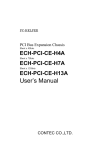
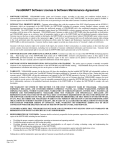
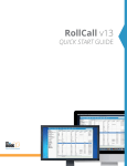
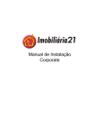
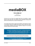
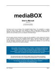
Universal Device Control Systems
www.udcsys.com
Local and Remote
Antenna A or B Coax Relay or Antenna Switch Controller
AOBAC User Manual Version 2.1
May, 2014
Universal Device Control Systems
Copyright © 2014 All Rights Reserved
Section
Content
Page
I
General Description
1
II
Control System Installation
1
III
System Control Button Label Customization
4
IV
Control System Operation
5
V
Trouble Shooting
5
VI
Remote Control Operation
5
Section I General Description
The AOBAC Control System provides users the ability to control a Normally Open or Normally Closed two
position Antenna A/B Coax relay or remote antenna switch with the click of a mouse while operating in the
shack or from a remote operating location using a remote desktop application or the UDCS/N4PY Integrated
Client Server System over a reliable Internet connection. Control system ports not used for this preconfigured
application can be used for other station control functions. Refer to the Application Notes Page at
www.udcsys.com for details.
AOBAC Control System Diagram
Voltage and Ground Source Control Examples
Tohotsu A/B Coax Relay
Top Ten Devices A/B Switch
Voltage Source
Ground Source
Default Software GUI Control Button Labels
No Antennas Selected
Antenna A Selected
Antenna B Selected
AOBAC Control System
Section II Installation
Please read and understand the Control System Software Quick Start Guide and instructions in this manual
before starting the installation process.
Note:
The AOBAC Controller can be configured to control either voltage source or ground source antenna relay or
coax switches. Examples of control lead connections are illustrated below. If the connection examples do not
apply to the type of A / B antenna switch to be controlled contact UDCS Support Services by telephone or email for assistance prior to installing the control system in order to avoid wiring errors and prevent possible
damage to the controller or antenna switch.
1
Controller Software Installation
Refer to the Control Software Quick Start Guide for details
• Insert the Control Software CD in the CDROM/DVD drive on the station computer
• Start the installation process by clicking Install
• Click OK and follow the installation prompts and click Finish to run the default application
• Ignore the hamShack Switch Not Found message by clicking OK
• After the default control window appears exit the program
Control System Hardware Installation
Voltage Source Antenna Relay - Normally Closed Antenna Relay (Tohotsu CX600M) (Refer to Figure 1)
• Plug the AOBAC USB cable into an unused USB port on the station computer
• Connect the red and black power cable to the station 13.8 Volt DC supply
• Start the AOBAC Control Program by clicking on the hamShack Switch desktop icon
• Verify control lead functionality
• Connect antenna relay power and control leads to the Controller barrier strip as shown in Figure 1
Figure 1
ABOC Voltage Source Switching Example ( Tohotsu A / B Antenna Coax Relay)
Ground Source Antenna Relay - Normally Open Antenna Relay (Top Ten Devices A/B Station Selector (Refer
to Figure 2 on Page 3)
• Plug the AOBAC USB cable into an unused USB port on the station computer
• Connect the red and black power cable to the station 13.8 Volt DC supply
• Start the AOBAC Control Program by clicking on the hamShack Switch desktop icon
• Verify control lead functionality
• Connect antenna switch control leads to the A /B Antenna Switch as illustrated in Figure 2
2
Figure 2
AOBAC Ground Source Switching Example (Top Ten Devices Antenna A / B Switch)
Remote A/B Antenna Switch or Coax Relay Power and Control Lead Connections
For proper operation most remote antenna coax relays or switches require a minimum of 12 VDC at the control
point. CAT 5 or other multi conductor cable of suitable gage can be used between the Control System and the
Antenna Switching Device. Refer to wire gage and cable length table below
Wire Gage (AWG)
24
22
Cable Length Limit
1,000 Feet
1,500 Feet
User provided Antenna Switch control cable preparation
If CAT 5 type cable is used refer to recommendations on Page 4
If other type multi conductor cable, prepare both ends of the power and control cable conductors
• Strip approximately 3/16” insulation and twist individual wires together
• Record conductor insulation colors for installation and troubleshooting reference
1
2
3
4
5
6
7
No Connection
3
8
CAT 5 Cable Code
Insulation Color
Brown
White / Brown
Green
White / Blue
Blue
White / Green
Orange
White / Orange
Recommended Conductor paring
Solid color – Ground
Stripe – 13.8 VDC
If a long control cable run is required,
ground unused conductors as a
precaution against RFI
Section III Control Button Label Customization
Control Window Label Change
To change AOBAC the AOBAC Default Label
Control Window Default Label
1. Click Settings
2. Default Label Displayed in the Call Sign area in Settings
AOBAC
3. Place cursor at the end of the last letter in the default label
4. Backspace to remove default label and type the desired label text:
Your call or other desired label
5.
Press the Enter Key to complete label change
Section Control Switch Label Customization
Default Label
Label customization Steps 1 – 7
Right Click on the left, center or right Switch Label areas
Default Label appears
Press the End Key
Backspace to clear the label
Type the desired Label Change
Press the Enter Key to change the label as desired (Example
“Antenna A / B Select”
7. Repeat the sequence to customize other label sections
1.
2.
3.
4.
5.
6.
Customized Label
1.
2.
3.
4.
5.
6.
To Change the Switch Center Label
Right click on the label area
Default Labels appears (Label as desired)
Place curser at the end of the text by hitting the End Key
Backspace to remove the current text
Type the new label text <<< Yagi
Vertical >>> and press Enter
to display the new center label
Antenna A and B Labels can be changed to Yagi and Vertical and
leave the center label area blank if desired
4
Section IV Control System Operation
To Select Antenna A or B
Place cursor in the Antenna A or B Button area and LEFT MOUSE BUTTON CLICK to select antenna A or B
System Control Relays are Self-Latching – the selected antenna remains connected when the controller is not activated
Click an illuminated button to unselect
Click Antenna A to Select
Click Antenna B to Select
No Antenna Selected
Antenna A Selected
Antenna B Selected
Section V Troubleshooting
1.
2.
3.
4.
Verify the USB cable is connected to the station control computer
Verify the DC Power cable is connected to the station supply as shown in Figure 1 and power is on
Verify control leads are functioning properly using a multi meter while switching controller directions
Click on the SGP Window Assignments button in the Settings Window to verify settings are unchanged
Should trouble persist after verifying all system settings and connections are correct and power is provided,
follow troubleshooting instructions in the manufacturers’ antenna switch user manual
Section V Remote Control Operation
There are two methods of operating the AOBAC system from a remote location by using a remote desktop
application or the UDCS/N4PY Integrated Client Server and rig control system.
Remote Desktop Application Control Method
Remote desktop applications enable users to see and control a connected PC as though they are sitting directly in
front of it. Remote desktop applications to include Citrix Systems GoToMyPC, LogMeIn, Symantec
pcAnywhere, RealVNC and later versions of Windows have remote desktop capability that can be used for
remote control operation. Depending on the quality of an Internet connection there may be some degree of
latency due screen refreshing as the system control software is running on the station computer.
5
UDCS / N4PY Integrated Client Server Method
The integrated Client – Server software feature provides a seamless Remote Radio Control System. Software
running on the Radio Server PC sends and receives commands and also receives status information from the
radio. Software on the client PC presents a graphical representation of radio controls and 6A2RAC control
functions. The client server system reduces latency as the control applications reside on the remote computer.
The radio’s frequency, mode, gain and other functions can be adjusted; antennas and other station equipment can
be selected or switched remotely using controller GUI Buttons. The Client Server Feature can also provide
automatic antenna switching and the ability to use paddles at the Remote Client end for sending CW.
Remote Client
Radio Server
To implement the Integrated Client Server function, purchase and install the version of N4PY Rig Control
Software for the type of radio to be used in the system. Follow instructions in the Client-Server and N4PY Rig
Control manuals for system configuration and operation details.
6