1
Programming Directive, 2011 Version 1.1
The Programming Directive describes the organizational procedures and the rules to be
observed when programming methods as part of FVV research projects. The goal of this
Directive is to ensure that the methods developed can be widely used and are of high quality.
Contents
Preamble .................................................................................................................................. 2
0. Area of application ............................................................................................................ 3
1. Objectives ......................................................................................................................... 4
2. Organizational procedure .................................................................................................. 5
3. Scope of results to be submitted regarding the method carrier ........................................ 6
4. Programming requirements............................................................................................... 7
4.1
Base platform ............................................................................................................. 8
4.2
Requirements in terms of method carrier running properties ..................................... 9
4.3
Requirements in terms of program implementation ................................................... 9
4.4
Program structure requirements ................................................................................ 9
4.5
Requirements in terms of source code and readability ............................................ 10
4.5.1
Naming ................................................................................................................. 10
4.5.2
Comments ............................................................................................................ 11
4.5.3
Readability............................................................................................................ 12
4.6
Quality Assurance .................................................................................................... 12
5. Documentation of method carriers .................................................................................. 13
5.1
Short program description ........................................................................................ 13
5.2
User documentation (User Manual) ......................................................................... 13
5.3
Source program ....................................................................................................... 14
5.4
Program documentation........................................................................................... 14
6. Real-time programs......................................................................................................... 16
7. Abbreviations .................................................................................................................. 17
8. Glossary .......................................................................................................................... 18
Seite 1 von 18
Preamble
FVV research projects help to improve the store of scientific knowledge, which often leads to
new models, equations or procedures. In most cases there is merit in documenting this gain
in knowledge (i.e. models, equations, etc.) not only in the final report but also in the form of
unambiguous source code. For this reason, this source code is also referred to as a “method
carrier”. It is not “software” in the sense of a product that is easy for end users to use. Rather,
it constitutes unambiguous documentation and a description of the findings that are obtained
in the form of programmed source text.
On the one hand, this creates less of a burden for the research institutes, since they do not
have to develop software in the sense of a product (i.e. no user interface development, it has
to be guaranteed to run only on a base platform, etc.); on the other, this means that the
demands on the quality of the source code have to be high, to ensure that member
companies can incorporate it into commercial products or in-house software without difficulty.
Source code almost always has to be adapted to enable integration into in-house software in
this way. It therefore has to be programmed in such a way that, once the project is
completed, software developers working for an FVV member who have previously not been
involved in the research project can understand the code without difficulty, incorporate it into
their own software, and validate the results against reference results from the FVV project.
The on-going research projects within FVV are too varied and different for any general,
binding regulation regarding the base platform, i.e. the programming language in particular,
to be of any practical value. The base platform, including the programming language, must
be determined by the discussion group for every project individually. Account must be taken
in this regard of the specific project requirements, previous FVV tasks, synergy effects with
on-going FVV tasks, ability of the method carrier to be used long-term, and also the level of
technical advance in the software development itself.
Seite 2 von 18
0. Area of application
The Programming Directive must be used if the specific objective of the research project is to
develop method carriers.
Even if the development of the method carrier is only one key step toward achieving the
objective of the project, or if it only becomes clear after the project has started that a method
carrier is being developed, it is still compulsory to use the Programming Directive. The
project committee and the research institute(s) may decide independently, but in consultation
with each other, regarding the boundary conditions for method development in the context of
the Programming Directive.
Seite 3 von 18
1. Objectives
The objectives of this Directive are to guarantee a defined quality standard and to improve
the usability of the method carrier.
The quality standard is defined by the following:
Absence of errors in code
Safeguarding the ability of the method carrier to run on the base platform(s) agreed upon
with the project committee
Portability of the method carrier code to other base platforms
Existence of an input and output description, and/or user guide
Integrated review of input data
Sufficient code commentary
Observance of all other requirements of the Programming Directive
Seite 4 von 18
2. Organizational procedure
The method carriers created while working on a research subject form a part of the results of
the research. These are drawn up by the research institute that is responsible for the
following:
The underlying physical and mathematical model and its coding
The general program sequence
The completeness of the method carrier, including the validation dataset (inputs and
outputs) and documentation
The FVV office shall assist the chairman and research institute in interpreting the Directive.
The task of the chairman is to coordinate the activities of the research institute, in
consultation with the project committee. No later than six months prior to the end of a project,
the research institute should submit an advance status report for the method carriers in
existence as of that point to the competent project-monitoring committee. The purpose of
this advance version of the method carrier is to enable agreement in principle as to whether
the research institute is on the right path in terms of programming style and documentation.
At this point the project committee must give the research institute feedback regarding
observance of the Programming Directive and the scope of the method carrier.
The project committee chairman shall declare the project successfully concluded only when
the project committee has declared the achieved status of the method carrier, including the
validation dataset and documentation, to be satisfactory.
Seite 5 von 18
3. Scope of results to be submitted regarding the method carrier
The methods developed in the research project must be submitted to the project committee
and FVV to the extent shown below:
Method carriers
o Complete source code
o Version capable of running
Validation data (input and associated result data in machine-readable form)
Handover workshop
Program documentation, incl. interface definition (see Chapter 5)
Description of development environment, including compiler settings (where relevant)
Description of base platform (version and configuration)
User Manual
The project committee is responsible for reviewing and approving documents and results.
Following conclusion of the project, the results will be made available on the FVV platform,
together with the final report. The research institute gives its assurance that the method
carrier is free of third-party rights.
Seite 6 von 18
4. Programming requirements
The competent FVV committees shall set down the rules that apply to the coding of new
method carriers. Such rules are set down in this Directive.
The rules are broken down into requirements for the following:
Scope of programming
Program structure
Running properties of the program
Ability of the program to be implemented on other base platforms
Code readability
Details of coding
Any use of third-party library subroutines
Freedom from third-party rights
Nature and scope of documentation
Any special features of the task
The research institute and the competent “project committee” are jointly responsible for
observing the rules. If, in an isolated instance, a problem should arise that is not covered by
the regulations, the research institute and the “project committee”, headed by the chairman,
shall agree on a solution. In such cases, the FVV office and the relevant FVV committees
must be advised about problems with the Programming Directive and the agreed solutions.
The following points must be noted in this regard, in particular:
It must be possible to import programs (method carriers) into another base platform
without significant additional action as a matter of course (requirements in terms of
implementation capability).
The programs (method carriers) must be structured in such a way that users can replace
or remove entire program sequences (program structure requirements).
The program must be written in a way that is easy to understand, so that details can be
clarified or amended with no need to contact the programmer (code readability
requirements).
In this context, the use of English comments and identifiers in the source text is
recommended, so as to make the results of the research accessible to the international
members of FVV. The language to be used shall be decided at the beginning of the
project by agreement between the chairman, project committee and research institute.
Every method carrier that is developed as part of an FVV research task must be
sufficiently documented.
This includes the following:
Short description of program (see Section 5.1)
User guide
Source program
Program documentation
Seite 7 von 18
4.1
Implementation notes
Research report containing a presentation of the physical and technical
principles, and also the mathematical methods.
Base platform
Definition:
The base platform is both necessary and sufficient for the implementation of the
method carrier, i.e. it enables it to be executed and makes available all of the
necessary prerequisites for work on the method carrier.
The base platform is in place from the start of the project. This does not rule out the
possibility of a later change to a newer version of the base platform by agreement
between the project committee and the research institute.
Availability must be assured, preferably for research institutes and all FVV members,
or for members of the project committee as a minimum. If, in a given case, the base
platform is not available to all members of the project committee, the possibility of
supporting another base platform in parallel must be examined. At the same time, this
ensures the portability of the method carrier.
Everything that is not a base platform is a method carrier, and must be supplied as
source code.
Examples of base platforms:
Compiler, interpreter, linker, libraries
Software package with standard language programming interface (e.g. to create
submodels)
Software package with visual programming interface (e.g. to develop functions for
engine control units or to represent a physical connection in this graphic
representation)
The base platform is determined in conjunction with the discussion group [“DG”] or the
project committee before the project begins. The following must be considered in the
selection process:
That the base platform supports the achievement of the project objectives. This also
implies that no undefined interactions between the base platform and the method
carrier are expected.
Those synergies with current and/or completed projects are drawn upon. FVV
programs were previously programmed in Fortran and ANSI C. It is preferable that
any extensions to these programs be programmed in these languages.
That the long-term usability of the method carrier is assured (i.e. robustness in the
face of version changes).
That account is taken of technical advances in programming.
If Fortran or C is chosen as programming languages at the beginning of the project,
programming should be done using Fortran 95 or ANSI C in accordance with ISO/IEC 9899.
Programs must be coded in accordance with applicable ANSI standards regardless of the
standard language in which they are programmed as a matter of course.
Program function and user interface must be kept separate in all cases.
Library modules that the research institute requires to guarantee the ability of the method
carrier to run shall either count as part of the base platform and be subject to the same
quality demands, or must be provided in the source code as part of the method carrier. If
Seite 8 von 18
these library modules are meant to count as part of the base platform, this must be
established within the DG before the project is awarded and documented in the Supplement.
4.2
Requirements in terms of method carrier running properties
Prior to Processing, the input data shall be checked for completeness, plausibility, and
possible violation of fixed array memory dimensions.
The program must be secured against crashes caused by undefined operations (e.g.
dividing by zero, square root of a negative number).
Iterative loops are terminated not only by way of accuracy bounds but also by way of a
counter. The bounds and counter can be defined in the software and/or be varied using
inputs. A system must be in place to notify users when the iteration limit is reached with
no convergence.
During normal program operation, no interactions (notifications or switch queries) or
pauses are permitted.
Data transfer between different programs in a software package is admissible if formatted
or in binary form. If binary files are used, a binary to 7-bit ASCII format converter must be
included in the software package.
Result data that is required in addition for further processing (e.g. charts) must be output
as a binary or 7-bit ASCII file, at the programmer’s option.
The elimination of graphics software must not compromise the function of the calculation
program.
4.3
Requirements in terms of program implementation
All arithmetic expressions must be coded only in one mode (i.e. only ‘real’ or ‘integer’).
The standardized conversion functions must be used for type conversions (e.g. ‘real’ _
‘Integer’).
All variables should be available as SI units wherever possible. Deviations must be
highlighted within variable names (e.g. p_Zyl_bar) or using comments.
In the case of Fortran, all variables must be declared using IMPLICIT NONE
All variables must be specified within the range of values that can be displayed and in
terms of resolution.
Parameters for accessing subroutines must be kept strictly separate, by ‘input’ and
‘output’.
Data field sizes must be easy to change at a central point in the program; the goal must
be to achieve dynamic memory management.
4.4
Program structure requirements
The main program essentially contains only subroutine accesses. Global data structures
must be avoided as much as possible.
If compiler-specific functions have to be used in exceptional situations, they must be
summarized and documented in a module of the software package. The same applies to
function accesses, e.g. differential equation solvers from commercial software packages
that are used as a base platform.
Seite 9 von 18
Individual subroutines should contain no more than 200 executable instructions, as far as
possible.
Wide use must be made of opportunities to structure programs in an easy-to-follow
manner and to transfer data between program components using structured data types.
Inputs, outputs and graphic accesses must be executed in separate subroutines in each
case.
Error messages contain a short description of the error and the name of the subroutine
that caused it.
The possibility of parallelization must be taken into consideration when drafting the
program structure.
Depending on the area of application (e.g. FEM, CFD), efforts should be made to
implement the program using 64-bit addressing from the outset.
The following applies as a matter of course with regard to Fortran:
Languages superseded with effect from Fortran 95 are no longer admissible. As
with the above statement regarding the use of global data structures, COMMON
blocks are admissible in Fortran only in specially justified exceptional cases and
in consultation with the project committee. Filling of COMMON blocks must be
performed on a standardized basis using an INCLUDE instruction in all affected
subroutines.
The objective must be to achieve linear program operation. The use of BLOCK IF
instructions or SELECT CASE constructs is preferred. Assigned GOTO,
computed GOTO und arithmetic IF instructions are not admissible.
In Fortran, named loops of the “DO … END DO” structure must be used.
4.5
Requirements in terms of source code and readability
Programs must be coded in self-documenting form, i.e. they must be structured in such a
way and with enough comments that third-party readers familiar with the report and literature
can find their way around without further aids and without asking the programmer.
4.5.1 Naming
Correct naming is the most decisive element when writing source code. Meaningful and selfevident names are essential to an intuitive understanding of the source code. A good choice
of name is a creative process that cannot be standardized in this document because it must
always be adapted to suit the context.
This Directive will not set down a naming convention, but it is important that a standardized,
meaningful naming process that will be understood at a general level is followed within the
project. The following convention is intended as a proposal for the research institute. If the
research institute wishes to use a different naming convention, it must advise the project
committee accordingly at one of the first sessions and document its own convention in
writing.
Hungarian notation (type prefix) is not used. The names of pointers form an exception to this
rule.
Compound identifiers are written using “camel hump” notation, i.e. the individual words within
the compound word each start with a capital letter. (E.g. getnextsample is written as
Seite 10 von 18
getNextSample). Separate rules apply to the use of upper and lower case letters for the first
letter of the identifier (see below).
As an alternative to camel hump notation, underscores may be used to represent subscripts,
based on TEX notation.
Naming of methods
Names of methods and functions always start with a verb. The first letter is therefore written
in lower case (based on German language usage). No prefix is put first (e.g.:
getNextSample()).
Method names must state precisely what the method does. Therefore, the initial verb must
be followed by a second part that describes what the “doing” relates to. This can be achieved
only if every method deals with precisely one task and not two, three or more.
Naming of constants
Names of constants are written entirely in upper case. Because visual word division using
“camel hump” notation is not possible in this case, the word elements must be separated
using a “_” (underline) symbol (e.g.: MAX_CYLINDER_COUNT).
Naming of variables
Names of variables / instances / objects normally begin with a noun. The first letter is
therefore written in upper case (based on German language usage). It must therefore be
ensured that the variable name offers precise information about the content or purpose of the
variable. Variable names such as “i”, “j” or “k” are admissible as loop indices.
Boolean variables must be labeled in such a way that readers automatically interpret
structures correctly.
Variables representing physical values and for which a standard symbol exists (e.g. pressure
p, temperature T), or for which a symbol has been introduced in the final project report,
should be identified using that symbol. This makes it easier to read formulae and also
simplifies the parallel reading of the final report and the source code. Upper and lower-case
conventions for these symbols must be strictly observed (e.g. pressure p and power P; time t
and temperature T). Standard symbols such as these should not be used incorrectly. To
ensure better readability, indices should be separated from the symbols, most of which
consist of a single letter, with an underscore (e.g. T_unburned, p_CylMotored). Non-SI units
must be labeled as part of the variable name, e.g. p_bar.
Example:
Declaration: bool IsValid;
bool HasNewValuesReceived;
real*8 p_CylinderMaxFired; /* max. cylinder pressure during combustion in
Pa*/
real*8 p_CylinderMaxMotored; /* max. cylinder pressure w/o combustion in
Pa*/
real*8 FiringPressureRatio; /* pressure ratio fired/motored */
in code:
if( IsValid ) {....}
if( HasNewValuesReceived ) {....}
FiringPressureRatio= p_CylinderMaxFired/ p_CylinderMaxMotored;
4.5.2 Comments
Programs must be coded in self-documenting form, i.e. they must contain enough
comments that third-party readers familiar with the report and literature can find their way
around without further aids.
Seite 11 von 18
Every program module contains the standardized program heading in accordance with
the “Standard program heading” form (see Annex 3, examples for FORTRAN and C in
Annexes 4 and 5) as well as a “history” list that provides information about changes in the
code.
The meaning / use of all variables and the physical unit must be stated as a comment in
the declaration.
The use of documentation systems such as Doxygen is generally recommended. In this
case deviations from the form in which the variable declaration is documented, as shown
in the “Standard program heading” form template, are admissible. It must then be
assured that the declaration of variables in comments includes the appropriate
information for automatic inclusion in the documentation.
4.5.3 Readability
Efforts must be made to achieve a structured (indented) layout in the source code. Empty
spaces in the structure must be generated using spaces rather than tabs.
Lines of code must not exceed 80 characters as a matter of course. This enables lines to
be output on terminals or on paper without being cut off. Lines may be longer if this
results in improved readability.
Program source code must use 7-bit ASCII. German accented or special characters are
not permitted (e.g. Ä = Ae; Ö= Oe; Ü = Ue; ß = ss). This also applies to comments in the
source text and data sets, if these are text files.
4.6
Quality Assurance
All methods should be implemented in the source code without error; in particular, there
should be no inconsistencies in the final report and source code. The research institute is
free to choose the methods that it uses for quality assurance. At the start of the project, the
research institute must advise the working group of the measures that it would like to use for
quality assurance, and when. Code reviews and version control systems are recommended.
When code reviews are used, it must be documented in all source code when the review was
performed, and by whom.
Seite 12 von 18
5. Documentation of method carriers
All of the following documentation must be stored on the Prometa server as separate files
together with the final documentation.
5.1
Short program description
The short description must enable users to learn whether the program is fundamentally
suited to resolving the problem in their subject area. The description must be written on a
form in accordance with the attached example (see form “Short Program Description”, Annex
8).
5.2
User documentation (User Manual)
The appropriate FVV templates must be used to document the method carrier (e.g. the
“Short Description”, see above). The user documentation contains all important information
that is needed to use a program or method carrier. The following in particular form part of the
user documentation:
a) Hints on installation and about the base platform
b) Input
Input form, if formatted text input datasets are imported from older FVV
programs
Clarification of input variables
Physical variables with a description of units and value range
Actuating variables with details of their function
Details of admissible input data ranges
Definitions and conventions regarding metrics and how to prepare them.
As appropriate, reference must be made to an appropriate explanation in the research
report or program manual.
c) Output
Explanation of output, e.g. for screen, storage media and, as appropriate, further
processing in the base platform (see Chapter 5.4), as well as the structure and
content of any potential result file. The output values must be documented in this
regard in terms of their meaning and the technical units used.
d) Error messages, re-start
Explanation of error messages
Description of corrective measures
Information on restarting following a premature program termination
e) Files
The nature, size and structure of the files used must be specified.
f)
Test examples
Input and output must be illustrated using one or more practical instances of
application.
This includes the following:
Computer-specific details (hardware, operating system, base platform and, as
appropriate, compiler plus options)
Input data sets and result files
Seite 13 von 18
5.3
Screen or printer output and/or graphic program output
Computing times, stating the hardware used
Memory requirement (internal / external)
Source program
The full source program for the method carrier, including any library modules to be supplied
by the research institute, must be stored on the FVV Prometa server immediately following
the conclusion of the research project, and be capable of retrieval at any time. FVV is
responsible for administration of the entire method carrier.
5.4
Program documentation
The program documentation must be maintained in such a way that errors can be corrected
and additions and alterations can be made to the program without particular difficulty. It must
be considered as a supplement to the user documentation and the final report.
This includes the following:
Rough block diagram (Annex 1)
Structure diagram (see Annex 6)
Short description of individual subroutines, similar to the program heading (see Annex
3 and/or Annexes 4 or 5)
Explanation of all agreed variables
Data flow charts, in the case of software packages
All interfaces to base platforms (i.e. third-party programs, libraries) must be documented in
such a way that they can be ported to any other desired base platforms.
This includes the following:
Details of the functions of the base platform that are used
List of arguments
o
Units and admissible value ranges for input and output variables
o
Interpretation of variables transmitted via the interface
Time and type of interactions between base platform and method carrier
Peculiarities of the base platform used (e.g. workarounds in the case of compiler
errors)
As appropriate, criteria that led to the selection of the base platform
As appropriate, in the case of mathematical procedures, a description of the
mathematical procedure within the base platform, if known and/or published
As appropriate, references in the literature to the base platform
Libraries that are not part of the base platform must be distributed as part of the method
carrier in the source code. They must be documented in the same way as the method carrier.
Seite 14 von 18
In addition, documentation must also be drawn up for every physical model or subroutine,
which may be done as part of the final project report.
Written preparation
Mathematical derivation and digital execution
Validity ranges and boundary conditions
Sample application examples (verification samples)
Model structure plan, i.e. overview of additional submodels
Seite 15 von 18
6. Real-time programs
The use of ANSI C (ISO/IEC 9899) is recommended when programming real-time-capable
programs. Because of the different structure of such software solutions, hardware-specific
expansions are needed and must therefore be co-ordinated precisely with the project
committee in each case.
Each program code to be programmed manually must be implemented in accordance with
“MISRA-C:2004 Guidelines for the Use of the C Language in Critical Systems”. This is based
on standard ISO/IEC 9899: Programming languages - C.
The following standards must be taken into consideration in the case of autocoding:
MISRA AC AGC - Guidelines for the application of MISRA-C:2004 in the context of automatic
code generation
MISRA AC GMG - Generic modelling design and style Guidelines
MISRA AC SLSF - Modelling design and style Guidelines for the application of Simulink and
Stateflow
And, as appropriate, MISRA AC TL - Modelling style Guidelines for the application of TargetLink in
the context of automatic code generation
Observance of MISRA standards must be checked automatically, where possible. The
appropriate tools must be selected by the project committee based on the project in question.
Because it is not possible for all MISRA rules to be checked by algorithms that run
automatically, some of these rules must be checked “manually”.
To ensure a clear allocation, a compliance matrix must be drawn up at the start of each new
project, which establishes which rule is to be checked using which method. If not all rules are
checked, this must be clearly noted in the matrix.
The program must be compiled in accordance with the rules in the attached Style Guide (see
Annex 9). The program structure must be modular. Modularization must follow the rules of
the Style Guide. Comments must also be provided in a modular fashion.
The above rules for documentation also remain valid for real-time-capable programs; in
addition, all functions must be shown in time flow charts (see Annex 7).
If the C code is generated using a process of automatic code generation, other types of
diagram may be used to document the C code, such as signal flow diagrams, state transition
diagrams and flow charts.
Seite 16 von 18
7. Abbreviations
DG
Discussion group
Seite 17 von 18
8. Glossary
Term
Method
Method carrier
Base platform
Software product
Software maintenance
Software commercialization
Definition
Abstract procedure / algorithm
Also a novel combination of proven techniques
Parameter derivation and/or identification from
trial results
Sample application
Documented core implementation of method (no
GUI, etc.) on a defined base platform
The base platform is necessary and sufficient to
enable execution of the method carrier
The base platform exists from the start of the
project
It is available for research institutes and all FVV
members, or for members of the project
committee as a minimum
Examples of base platforms are: Excel,
MATLAB, higher programming languages, CAE
software, etc.
Everything that is not a base platform is a
method carrier, and must be supplied as source
code.
Generally applicable, parameterized overall
application, including the following:
– Method
– Data model structure
– User interface (e.g. pre-/postprocessor)
– Product documentation
– Version check
– Error handling methods
– Porting
– Regression tests
– Installation program
– Integration with other software products, as
appropriate
– Certification
– …
– Further development and maintenance regarding
the following:
– State of the art in terms of method
– Software performance
– Stability
– General quality (bug fixing)
– Adaptation to changeable hardware and OS
requirements
Commercial retail and service worldwide, without
exception, subject to legal boundary conditions
Seite 18 von 18
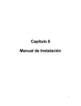
Annex 1
Example of modular program structure
Main prog
.
Functions:
+ Import command
parameters
+ Data exchange
between modules
+ Control program
sequence
+ Return status at end
(e.g. ERRORLEVEL)
Prog. mod. start I/O
Functions:
+ Read in data
+ Check data
+ Transfer data
Prog. mod. processing
Functions:
+ Import data
+ Calculate
+ Return data
Prog. mod. end I/O
Functions:
+ Import data
+ Save and/or return
data
Annex 2
Example of arrangement of DO loop labels in Fortran:
DO L=1,LMAX
DO J=1,JMAX
A=Y(J,L)
DO I=1,IMAX
X(I,J,L)=Z(L)*A
END DO
DO I=1,IMAX
T(I,J,L)=X(I,J,L)**2-A
END DO
END DO
DO J=1,JMAX
B=Y(J,L)**2
C(J,L)=PI*B
D(J,L)=28.5*(B-5.)
END DO
END DO
Annex 3
Model for comments on program / subroutine headers
Explanation of program function in one sentence
Author
Institution
University
Date
Language
Project
FVV no.
J. Smith
Institute of Applied Computer Science
Podunk University
11.11.2011
Fortran 95
Crankcase lighting
4711
Code Review
Review I
Review II
Reviewer
Dr. X. Troubleshooter
Prof. Head
Variable name
Type
A
R
X
History:
Version
V 1.0
V2.0
…
On/Off
Date
16.02.1999
28.02.1999
Unit
Explanation of variable
Real*4 On
Real*4 On
Real*4 Off
m**2
KJ/kg K
m
Heat-transferring surface of piston head
Gas constant
Piston stroke
Date
2004-07-07
2007-11-30
Author
J. Smith
Mrs F. Smith,
IACS, Podunk
University
Comment
Document created
Formal revision in FVV M815
Implementation based on:
- MERKER, Günter; SCHWARZ, Christian; STIESCH, Gunnar; OTTO, Frank:
Verbrennungsmotoren. Simulation der Verbrennung u. Schadstoffbildung.
2nd ed. Stuttgart: Teubner, 2004
- PISCHINGER, R. ; KLELL, M. ; SAMS, T.: Thermodynamik der
Verbrennungskraftmaschine. 2nd ed. Vienna: Springer, 2002.
Annex 4
Example of a program in Fortran 95
!
!
!
!
!
!
!
!
!
!
!
!
!
!
!
!
!
!
!
!
!
!
!
!
!
!
!
!
!
!
!
!
!
!
!
!
!
!
!
!
!
!
Subroutine to calculate heat transfer based on Woschni
Author:
J. Smith
Institution:
Institute of Applied Computer Science
University:
Podunk University
Date:
2004-07-07
Language:
Fortran 95
Project:
Crankcase lighting
FVV no.:
4711
------------------------------------------------------------------------Review I:
Dr. X. Troubleshooter, 2004-07-09
Review II:
Prof. Head, 2004-12-10
------------------------------------------------------------------------Amended:
Mrs. F. Smith
Date:
2009-11-18
Institution:
Institute of Applied Computer Science
University:
Podunk University
Project:
Crankcase lighting
FVV no.:
4711
------------------------------------------------------------------------Variable
Type
Input/Output Unit Description
------------------------------------------------------------------------p
real*8
I
(Pa)
Pressure in cylinder
T
real*8
I
(K)
Mean temp. in cylinder
p_ES
real*8
I
(Pa)
Pressure in cylinder with
inlet closing (ES)
T_ES
real*8
I
(K)
Temp. in cylinder with ES
V_ES
real*8
I
(m^3)
Vol. in cylinder with ES
V_Hub
real*8
I
(m^3)
Cylinder displacement
d_Zyl
real*8
I
(m)
Cylinder diameter
c_m
real*8
I
(m/sec) Mean piston speed
c_u_Drall
real*8
I
(m/sec) Swirl velocity
p_Schlepp
real*8
I
(Pa)
motored pressure profile
without combustion
isGasExchange logical I
(-)
Indicates whether charge exchange
present or not
alpha
isValid
! History:
! -------! Version
! V 1.0
! V 1.1
cycles
real*8
logical
Date
20040707
20040709
O
O
Name
Smith
Smith
(W/m^2/K) Heat transfer coefficient
Error flag 0: Error 1: OK
Description
Document created
Huber activated only for whole engine
!
!
!
!
to
!
!
!
V 1.2
20041210
Smith
V
V
!
V
V
1.45
1.52
20070615
20081216
Smith
Smith
1.54
1.55
20091001
20091118
Smith
Smith
alpha_uv no longer calculated for empty
areas
Minor internal redesign (DataMain%geo)
Improved oscillation control in response
turning Huber expansion on or off
Clean error message if alpha = NaN
No further crashes caused by extreme
combustion term
! Implementation based on:
!
- MERKER, Günter; SCHWARZ, Christian; STIESCH, Gunnar; OTTO, Frank:
!
Verbrennungsmotoren. Simulation der Verbrennung u. Schadstoffbildung.
!
2nd ed. Stuttgart: Teubner, 2004
!
- PISCHINGER, R. ; KLELL, M. ; SAMS, T.: Thermodynamik der
!
Verbrennungskraftmaschine. 2nd ed. Vienna: Springer, 2002.
subroutine calcAlphaWoschni( p, T, p_ES, T_ES, V_ES, V_Hub, d_Zyl, c_m,
c_u_Drall, p_Schlepp, isGasExchange, alpha,
isValid )
implicit none
! Arguments
real*8, intent(in)
real*8, intent (in)
real*8, intent (in)
real*8, intent (in)
real*8, intent (in)
real*8, intent (in)
real*8, intent (in)
real*8, intent (in)
real*8, intent (in)
real*8, intent (in)
logical, intent (in)
::
::
::
::
::
::
::
::
::
::
::
p
T
p_ES
T_ES
V_ES
V_Hub
d_Zyl
c_m
c_u_Drall
p_Schlepp
isGasExchange
real*8, intent (out) :: alpha
logical, intent (out) :: isValid
!
!
!
!
!
!
!
!
!
!
!
(Pa) Pressure in cylinder
(K) Mean temp. in cylinder
(Pa) Pressure in cylinder with ES
(K) Temp. in cylinder with ES
(m^3) Vol. in cylinder with ES
(m^3) Cylinder displacement
(m) Cylinder diameter
(m/s) Mean piston speed
(m/s) Swirl speed
(Pa) motored pressure profile
Indicates whether in charge
exchange
! (W/m^2/K) Heat transfer coefficient
! Error flag 0: Error 1: OK
! Internal variables:
real*8 :: C1, C2
! Constants based on Woschni
real*8 :: p_bar, p_ES_bar, p_Schlepp_bar ! (bar) converted pressures
real*8 :: delta_p_bar
! (bar) pressure differential,
fired
real*8 :: zh1, zh2
! Auxiliary variables
if (p > 0.0 .and. p_ES > 0.0) then ! valid pressure?
C2=3.24*0.001
! Constant C2
if (isGasExchange) then
C1=6.18+0.417*(c_u_Drall / c_m) ! Constant C1 for charge exchange
else
C1=2.28+0.308*(c_u_Drall / c_m) ! Constant C1 for high pressure phase
end if
! Variables with non-SI compliant units must be
! clearly labeled
p_bar = p*1e-5
p_ES_bar = p_ES*1e-5
p_Schlepp_bar = p_Schlepp*1e-5
zh1 = 130.0 * (d**(-0.2))*(p_bar**0.8)*(T**(-0.53))
delta_p_bar = p_bar - p_Schlepp_bar
if (delta_p_bar > 0.0) then
! must not be negative
! Calculate combustion term based on Woschni:
zh2 = ( C1 * c_m + C2 * ((V_Hub * T_ES) / (p_ES_bar * V_ES)) *
delta_p_bar)**0.8
else
zh2 = ( C1 * c_m )**0.8
endif
alpha=zh1*zh2
! (W/m^2/K) Heat transfer coefficient
isValid = .true.
else
alpha = 0.0
isValid = .false.
end if
! Error invalid pressure
end subroutine calcAlphaWoschni
Annex 5
Example of a program in C
/*
------------------------------------------------------------------------Subroutine to calculate heat transfer based on Woschni
------------------------------------------------------------------------Author:
J. Smith
Institution:
Institute of Applied Computer Science
University:
Podunk University
Date:
2007-07-07
Language:
ANSI C
Project:
Crankcase lighting
FVV no.:
4711
------------------------------------------------------------------------Review I:
Dr. X. Troubleshooter, 2004-07-09
Review II:
Prof. Head, 2004-12-10
------------------------------------------------------------------------Amended:
Mrs. F. Smith
Date:
2009-11-18
Institution:
Institute of Applied Computer Science
University:
Technical Podunk University
Project:
Crankcase lighting
FVV no.:
4711
------------------------------------------------------------------------Variable Type
Input/Output Unit Description
------------------------------------------------------------------------p
real*8
I
(Pa)
Pressure in cylinder
T
real*8
I
(K)
Mean temp. in cylinder
p_ES
real*8
I
(Pa)
Pressure in cylinder with
inlet closing (ES)
T_ES
real*8
I
(K)
Temp. in cylinder with ES
V_ES
real*8
I
(m^3)
Vol. in cylinder with ES
V_Hub
real*8
I
(m^3)
Cylinder displacement
d_Zyl
real*8
I
(m)
Cylinder diameter
c_m
real*8
I
(m/sec) Mean piston speed
c_u_Drall
real*8
I
(m/sec) Swirl velocity
p_Schlepp
real*8
I
(Pa)
Working gas pressure
without combustion
isGasExchange
logical I
(-)
Indicates whether charge exchange
present or not
isValid
logical
O
Error flag 0: Error 1: OK
History:
-------Version
V 1.0
V 1.1
cycles
V 1.2
Date
20040707
20040709
Name
Smith
Smith
Description
Document created
Huber activated only for whole engine
20041210
Smith
V 1.45
V 1.52
20070615
20081216
Smith
Smith
V 1.54
V 1.55
20091001
20091118
Smith
Smith
alpha_uv no longer calculated for empty
areas
Minor internal redesign (DataMain%geo)
Improved oscillation control in response
to turning Huber expansion on or off
Clean error message if alpha = NaN
No further crashes caused by extreme
combustion term
Implementation based on:
- MERKER, Günter; SCHWARZ, Christian; STIESCH, Gunnar; OTTO, Frank:
Verbrennungsmotoren. Simulation der Verbrennung u. Schadstoffbildung.
2nd ed. Stuttgart: Teubner, 2004
- PISCHINGER, R.; KLELL, M. ; SAMS, T.: Thermodynamik der
Verbrennungskraftmaschine. 2nd ed. Vienna: Springer, 2002.
*/
double calcAlphaWoschni( p, T, p_ES, T_ES, V_ES, V_Hub, d_Zyl, c_m,
c_u_Drall, p_Schlepp, isGasExchange,
isValid )
{
//Internal variables:
double C1, C2;
double p_bar, p_ES_bar, p_Schlepp_bar;
double delta_p_bar;
fired
double zh1, zh2;
double alpha;
coefficient
// Constants based on Woschni
// (bar) converted pressures
// (bar) pressure differential,
// Auxiliary variables
// (W/m^2/K Heat transfer
if (p > 0.0 && p_ES > 0.0)
// valid pressure?
{
C2=3.24*0.001;
// Const. C2
if (isGasExchange)
/* Const. C1 for charge exchange */
C1=6.18+0.417*(c_u_Drall / c_m);
else
/* Const. C1 for high pressure phase */
C1=2.28+0.308*(c_u_Drall / c_m);
/* Variables with non-SI compliant units must be
clearly labeled */
p_bar = p*1e-5;
p_ES_bar = p_ES*1e-5;
p_Schlepp_bar = p_Schlepp*1e-5;
zh1 = 130.0 * pow(d,-0.2) * pow(p_bar,0.8) * pow(T, -0.53);
delta_p_bar = p_bar - p_Schlepp_bar;
if (delta_p_bar > 0.0)
/* must not be negative */
{
/* Calculate combustion term based on Woschni: */
zh2 = pow( C1 * c_m + C2 * ((V_Hub * T_ES) / (p_ES_bar * V_ES)) *
delta_p_bar, 0.8 );
}
else
{
zh2 = pow( C1 * c_m, 0.8);
}
alpha=zh1*zh2;
/* (W/m^2/K) Heat transfer coefficient */
isValid = true;
}
else
{
alpha = 0.0;
isValid = false;
}
return alpha ;
}
/* Error invalid pressure */
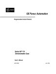
Annex 6
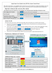
Example of program structure plan
Interpolation of
external loads
Calculation
interpol.f
extloads.f
ctype1.f
constraints.f
ctype2.f
Calculation of
constraining forces
for different
connecting
elements
Calculate global
movement
solvesys.f
solvenlin.f
gmotion.f
Control of calculation
process
setuplin.f
vibration.f
factorlin.f
Calculate oscillatory
movement
solvelin.f
Draft and solve linear equation
system
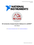
Annex 7
Example of a time plan
Annex 8
Short program description
Name of program
Short project title
Project no.
Research institute
Head of research institute
Authors
Date created
Version
Revised by
Purpose of method
Keywords
Programming language
Requirements in terms of:
System environment
Available interfaces
Important notes
Annex 9
Real-time programs
Explanation of term – Real-time programs
1.1
Group
A software design unit with clearly delimited functionality and defined interfaces; it may
consist of multiple components (e.g. the COM group contains all communications
components).
1.2
Component
A software design unit with clearly delimited functionality and defined interfaces within a
group (e.g. CCP, KWP).
1.3
Module
In the programming sense, a file (also known as a Source File) that may consist of a
series of operations (functions), type declarations, variables and constants. Every module
is physically stored under a specific name that describes the content of the module as
precisely as possible. Each module is thus the smallest compilable programming unit (see
Annex A on module structure).
To achieve better software quality in terms of ease of maintenance and readability, the
whole of the source code for a given program must be structured in modular form, i.e.
comprising, where possible, several modules (program files) that can be individually
compiled, each describing a specific situation. Module names must reflect the overall task
performed by all operations contained in the module in question. Some examples are
listed below (modules are C files).
Example:
CCP.C
KWP.C
Notes:
• Components are abbreviated in all names for non-local objects
• Show the memory class in names (_var vs. var vs. var_ for module-global, local,
persistent-local, for example)
• Mandatory and comprehensive use of const
• Mandatory use of module-global, not externally visible operations wherever possible
o Use static
o Omit module abbreviation
o Position in source text ahead of global, externally visible operations
• The same applies to data objects
Source
A F T Atlas Fahrzeugtechnik GmbH
Page 1/16
Annex 9
1.4
Operation (function)
This is part of a module, consisting of the operation name and a sequence of instructions.
An operation has a defined input and output.
Group: COM
Component: CCP
Component: KWP
Module: CCP.C
Module: KWP.C
Operation1
Operation1
Operation2
Operation2
Associated module: CCP.H
Associated module: KWP.H
This arrangement can be simplified as required (if a group contains only one component)
or refined.
Source
A F T Atlas Fahrzeugtechnik GmbH
Page 2/16
Annex 9
Style Guide – real-time programs (ref. Chapter 4)
1.5
Style Guide
The MISRA standard “Guidelines For The Use Of The C Language In Vehicle Based
Software” makes available a series of rules that are intended to support the programming
of correct C programs. These rules relate mainly to the details of the programming
language C and say nothing about the programming style (i.e. a style guide). For this
reason, this chapter should be considered as a supplement to the MISRA standard insofar
as it provides a definition of the Style Guide.
Note: (MISRA: R111) identifies MISRA rule 111 as reference.
1.5.1 Data types
1.5.1.1 Basic data types
The data types to be used must be defined as a matter of course via “compiler switches”
for different processors or compilers. The basic data types listed in the following table
must be used so as to exclude differing interpretations of data types on different systems.
The data types offered by the compiler must be converted into the following basic data
types.
ECU designation
Data width
bool
s8
u8
s16
u16
s32
u32
s64
u64
f32
f64
f128
8 bit
8 Bit
8 Bit
16 Bit
16 Bit
32 Bit
32 Bit
64 Bit
64 Bit
32 Bit
64 Bit
128 Bit
ANSI data type
(e.g. MPC 565)
signed char
unsigned char
signed int
1.5.1.2 Derived data types
Further data types can now be derived from the basic data types. These are labeled with
a suffixed “_t”.
1.5.1.3 Structures / bit variables
The data types used in the bit variables must be declared using ANSI-C. Derived
“typedefs” are compiler-dependent and lead to errors.
Source
A F T Atlas Fahrzeugtechnik GmbH
Page 3/16
Annex 9
typedef struct
{
unsigned int
unsigned int
unsigned int
.
.
.
}bitword_t
bit1_b:1
bit2_b:1
bit3_b:1
(MISRA: R111-R113)
1.5.1.4 Type conversion
Type conversion must be done only explicitly. By doing so, the user shows that the
conversion was intentional. Implicit type conversions are compiler-dependent. This means
that the program is not portable and the data types are not predictable.
(MISRA: R43-R45)
1.5.1.5 Pre-processor arithmetic
Pre-processor constants that are used for pre-processor arithmetic must be declared by
stating the data type “double” or “float”. The desired data type must then be stated
explicitly (as “cast”).
(MISRA: R87-R100)
Examples:
#define ADC_LOOP_TIME_C
( (f64) 1000 )
#define ADC_FACTOR_C
( (f64) 0.01 )
#define ADC_VALUE_C
( (u16) ADC_LOOP_TIME_C * ADC_FACTOR_C )
Source
A F T Atlas Fahrzeugtechnik GmbH
Page 4/16
Annex 9
1.5.1.6 Declaring data masks (masks)
Data masks must be declared using compiler switches, since the bit structure and byte
arrangement are processor-dependent. “Else branches” need to be defined.
The control flow of instructions must be made clear using indents.
Examples:
#ifdef INTEL
#define MASK 0x0001
#elif MOTOROLA
#define MASK 0x0100
#else
#error message_no_processor
#endif
1.5.2 Naming conventions
Clarity, ease of maintenance and compatibility (within a programming team) are
guaranteed if meaningful names and a standardized writing format are adopted for
variables, constants, structures, etc. Because one objective is to ensure that the existing
software can be re-used, the names for the language elements listed above should be,
and remain, non-project-dependent. Names must communicate meaning and not be made
too short. In extreme cases they should be abbreviated in a way that still reflects their
sense. It must be ensured in this regard that the designation chosen does not conflict with
the reserved names in the programming environment (compiler, linker, programming
language etc.).
All identifiers belonging to a functional module must begin with a defined abbreviation.
Where possible, the abbreviation should be limited to three letters.
Source
A F T Atlas Fahrzeugtechnik GmbH
Page 5/16
Annex 9
1.5.2.1 Names of variables
Names of variables are structured as shown below:
[abbreviation]_DescriptionOfVariables]_[variabletype]
abbreviation
-
Name of the associated components, in lower case
DescriptionOfVariables
-
Logical description of the variables, with no
separation of individual words with an underscore,
but identified instead using upper and lower case
letters
variabletype
-
s8, u8, s16, u16, s32, u32, s64, u64, f32, f64, f128
Examples:
adc_BatteryVoltage_u16
/* Analog value for battery voltage */
can_ReceiveBuffer_u8[8]
/* CAN receive buffer */
There is no need to use the component description with local variables (within the
operations).
1.5.2.1.1
Pointer
Pointer names are formed in accordance with the requirements for variable names, with
the difference that the variable type is replaced by the character sequence “_p” (pointer).
[abbreviation]_[DescriptionOfVariables]_p
Examples:
can_TransmitBuffer_p
/* CAN transmit buffer */
Source
A F T Atlas Fahrzeugtechnik GmbH
Page 6/16
Annex 9
1.5.2.1.2
Structure variables
Structure variables are formed in accordance with the requirements for variable names,
with the difference that the variable type is replaced by the character sequence “_st”
(structure).
[abbreviation]_[DescriptionOfVariable]_st
Examples:
can_Bitfeld_t can_ErrorStatus_st
/* CAN Status */
1.5.2.2 Applicable values
Applicable values (characteristic values, characteristic curves, characteristic diagrams)
are described as follows:
[abbreviation]_[Description]_[identifier]
abbreviation
-
Name of the associated components, in lower case
Description
-
Logical description of the variables, with no
separation of individual words with an underscore,
but identified instead using upper case letters
kw, kl, kf, kr (no data type specified)
kw – characteristic value
kl – characteristic curve
kf – characteristic map
(kr – characteristic volume)
identifier
Examples:
adc_TempSensor_kl
/* Sensor characteristic curve */
adc_TempSensorThreshold_kw
/* Sensor threshold value */
1.5.2.3 Names of operations
Names of operations are structured in the same way as names of variables, with the
following difference:
• The variable type describes the return value of the operation; if the operation does not
produce a value (i.e. if it is void), this description is not used.
[abbreviation]_[DescriptionOfOperation]_[variabletype]( )
abbreviation
-
Name of the associated components, in lower case
DescriptionOfOperation
-
Logical description of the operation, with no
separation of individual words with an underscore,
Source
A F T Atlas Fahrzeugtechnik GmbH
Page 7/16
Annex 9
but identified instead using upper case letters
variabletype
-
s8, u8, s16, u16, s32, u32, s64, u64, f32, f64, f128
Examples:
u8 can_TransmitData_u8 ()
void can_BusOff ()
Source
A F T Atlas Fahrzeugtechnik GmbH
Page 8/16
Annex 9
1.5.2.4 Constants by defines
Constants are written in upper case, with the attached character string “_C”, as shown
below:
[ABBREVIATION]_[DESCRIPTION_OF_CONSTANTS]_C
ABBREVIATION
-
Name of the associated components, in upper
case
DESCRIPTION_OF_CONSTANTS
-
Logical description of the operation, with
individual words separated with an underscore
•
•
Constants must be enclosed in parentheses.
They must be explicitly defined by data type.
Examples:
#define CAN_RECEIVE_BUFFER_LENGTH_C
( (u8)8 )
1.5.2.5 Macros
Macros are written in upper case. The name of the macro is followed immediately by a
pair of parentheses “()”.
[ABBREVIATION]_[DESCRIPTION_OF_MACRO]( )
ABBREVIATION
-
Name of the associated components, in upper
case
DESCRIPTION_OF_MACRO
-
Logical description of the macro, with individual
words separated with an underscore
Examples:
CAN_NEWDAT_SET()
(MISRA: R90-R96)
Source
A F T Atlas Fahrzeugtechnik GmbH
Page 9/16
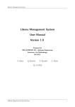
Annex 9
1.5.2.6 Header files
The names of header files must be described using the abbreviations that signal
attribution to a given component. This encourages clarity, attribution and ease of
maintenance of the software. The illustration below shows the principle to be followed
when creating header files.
Defines, macros, operations
belonging to each module
Group: COM
Component: CCP
Module: CCP.C
Component: KWP
Associated
group:
COM.H
Module: KWP.C
Module: CCP_APL.C
Operation1
Operation1
Operation1
Operation2
Operation2
Operation2
Associated module: CCP.H
Global (applicable to
entire group)
Associated module: KWP.H
Defines and macros not module-specific,
within a given component element
Modules may have their own header files.
Source
A F T Atlas Fahrzeugtechnik GmbH
Page 10/16
Annex 9
1.5.3 Project files
1.5.3.1 Fundamental properties
• No tabs must be used.
• Indent: 3 spaces
• Line length must not exceed 120 characters.
• Brackets belonging together must be positioned above each other.
if( )
{
}
else
{
}
•
•
Accented and other special characters such as ä, ö, ü and ß are not permitted.
Blank spaces must be placed between operators: x + y
1.5.3.2 Module structure
To ensure that the code is consistent and readable, a module header (see Annex A) must
be included in every program file. An operation header (see Annex B) must be created for
each operation.
1.5.4 Predefined compiler macros and data types
Predefined data types and macros must not be used, since these are entirely dependent
on the compilers used.
1.5.5 Return instruction
A maximum of one return instruction may be used within an operation as the last
instruction.
(MISRA: R79-R86)
1.5.6 Comments
Comments must explain “what” is done and “why”, but not “how”. Comments must not be
nested. Program codes must not be repeated in words.
1.5.7 Program code
1.5.7.1 Conditional compiling
In principle, provision must be made for conditional compiling for different processors or
hardware variants, etc., even if only one processor is used. This makes expansion or
portability possible. The “else branch” is used for error handling and must be provided.
The control flow must be made clear using indents.
Examples:
Source
A F T Atlas Fahrzeugtechnik GmbH
Page 11/16
Annex 9
#ifdef INTEL
....
#elif MOTOROLA
.....
#else
#error message_no_processor
#endif
1.5.7.2 Change documentation for program code
Program code changes are documented by way of the appropriate entries in the program
version control system (PVCS).
Source
A F T Atlas Fahrzeugtechnik GmbH
Page 12/16
Annex 9
Annex A – Structure of a C file (module)
The C file is a collection of operations that are linked with each other either logically or
functionally. This file is called a module. Each file contains only one module header at the
start of the file. The structure and content are shown below.
/*****************************************************************
PROJECT:
MSP0208
$Header:
$
NAME:
$Workfile: $
CREATE DATE:
2002-09-24
CODING STANDARD:
DESCRIPTION:
REVISION:
$Revision: $
$Author:
$
$Date:
$
LIST OF CHANGES:
$Log:$
*****************************************************************/
/*---------------------------------------------------------------Header files (#include)
----------------------------------------------------------------*/
/*---------------------------------------------------------------Global variables
----------------------------------------------------------------*/
/*---------------------------------------------------------------Global constants (const)
----------------------------------------------------------------*/
/*---------------------------------------------------------------Globally applicable parameters (const)
----------------------------------------------------------------*/
/*---------------------------------------------------------------Type definitions within the module (typedef)
----------------------------------------------------------------*/
/*---------------------------------------------------------------Constants within the module by Define (#define)
----------------------------------------------------------------*/
/*---------------------------------------------------------------Macros within the module (#define, inline)
----------------------------------------------------------------*/
/*---------------------------------------------------------------Variables within the module (static)
----------------------------------------------------------------*/
Source
A F T Atlas Fahrzeugtechnik GmbH
Page 13/16
Annex 9
/*---------------------------------------------------------------Constants within the module (static const)
----------------------------------------------------------------*/
/*---------------------------------------------------------------Parameters applicable within the module (const)
----------------------------------------------------------------*/
/*---------------------------------------------------------------Operation prototypes within the module (static)
----------------------------------------------------------------*/
Source
A F T Atlas Fahrzeugtechnik GmbH
Page 14/16
Annex 9
Annex B – Structure of an operation
The following shows the basic structure to be used for each operation.
/*****************************************************************
NAME OF OPERATION:
NameOfOperation
DESCRIPTION:
INPUTS:
OUTPUTS:
AUTHOR/DATE:
*****************************************************************/
void NameOfOperation(void)
{
} /* End NameOfOperation */
Note:
All variables (parameters, global variables) that are read or described must be listed and
described under INPUTS / OUTPUTS.
Source
A F T Atlas Fahrzeugtechnik GmbH
Page 15/16
Annex 9
Annex C – Structure of a header file
/*****************************************************************
PROJECT:
MSP0208
$Header:
$
NAME:
$Workfile: $
CREATE DATE:
2002-09-24
CODING STANDARD:
DESCRIPTION:
REVISION:
$Revision: $
$Author:
$
$Date:
$
LIST OF CHANGES:
$Log:$
*****************************************************************/
#ifndef header_h
#define header_h
/*---------------------------------------------------------------Global type definitions (typedef)
----------------------------------------------------------------*/
/*---------------------------------------------------------------Global constants by Define (#define)
----------------------------------------------------------------*/
/*---------------------------------------------------------------External definitions of global variables
----------------------------------------------------------------*/
/*---------------------------------------------------------------External definitions of global constants
----------------------------------------------------------------*/
/*---------------------------------------------------------------External definitions of operation prototypes
----------------------------------------------------------------*/
/*---------------------------------------------------------------Global macros (#define)
----------------------------------------------------------------*/
Source
A F T Atlas Fahrzeugtechnik GmbH
Page 16/16
Annex 9